EP3584010A1 - Methode d'etude d'un et/ou avec un echantillon biologique - Google Patents
Methode d'etude d'un et/ou avec un echantillon biologique Download PDFInfo
- Publication number
- EP3584010A1 EP3584010A1 EP19188161.4A EP19188161A EP3584010A1 EP 3584010 A1 EP3584010 A1 EP 3584010A1 EP 19188161 A EP19188161 A EP 19188161A EP 3584010 A1 EP3584010 A1 EP 3584010A1
- Authority
- EP
- European Patent Office
- Prior art keywords
- sample
- cell culture
- cells
- cell
- examined
- Prior art date
- Legal status (The legal status is an assumption and is not a legal conclusion. Google has not performed a legal analysis and makes no representation as to the accuracy of the status listed.)
- Withdrawn
Links
- 238000000034 method Methods 0.000 title claims abstract description 65
- 239000012472 biological sample Substances 0.000 title claims abstract description 41
- 238000011835 investigation Methods 0.000 title claims description 12
- 239000000523 sample Substances 0.000 claims abstract description 339
- 239000000126 substance Substances 0.000 claims abstract description 77
- 239000000463 material Substances 0.000 claims abstract description 47
- 210000004027 cell Anatomy 0.000 claims description 173
- 238000004113 cell culture Methods 0.000 claims description 89
- 230000000694 effects Effects 0.000 claims description 30
- 230000004888 barrier function Effects 0.000 claims description 22
- 230000010412 perfusion Effects 0.000 claims description 22
- 210000004881 tumor cell Anatomy 0.000 claims description 21
- 239000013543 active substance Substances 0.000 claims description 20
- 238000004458 analytical method Methods 0.000 claims description 20
- 239000004480 active ingredient Substances 0.000 claims description 17
- 238000004720 dielectrophoresis Methods 0.000 claims description 17
- 230000003287 optical effect Effects 0.000 claims description 16
- 244000052769 pathogen Species 0.000 claims description 16
- 238000006243 chemical reaction Methods 0.000 claims description 14
- 230000003993 interaction Effects 0.000 claims description 14
- 102000004190 Enzymes Human genes 0.000 claims description 12
- 108090000790 Enzymes Proteins 0.000 claims description 12
- 238000011534 incubation Methods 0.000 claims description 12
- 239000011159 matrix material Substances 0.000 claims description 11
- 230000006870 function Effects 0.000 claims description 9
- 230000001717 pathogenic effect Effects 0.000 claims description 9
- 238000003752 polymerase chain reaction Methods 0.000 claims description 9
- 238000000926 separation method Methods 0.000 claims description 9
- 230000008859 change Effects 0.000 claims description 8
- 102000039446 nucleic acids Human genes 0.000 claims description 8
- 108020004707 nucleic acids Proteins 0.000 claims description 8
- 150000007523 nucleic acids Chemical class 0.000 claims description 8
- 238000010186 staining Methods 0.000 claims description 8
- 238000001493 electron microscopy Methods 0.000 claims description 7
- 230000003915 cell function Effects 0.000 claims description 6
- 210000003850 cellular structure Anatomy 0.000 claims description 6
- 239000003086 colorant Substances 0.000 claims description 5
- 238000003018 immunoassay Methods 0.000 claims description 5
- 238000004949 mass spectrometry Methods 0.000 claims description 5
- 230000000771 oncological effect Effects 0.000 claims description 5
- 239000003440 toxic substance Substances 0.000 claims description 5
- 108010026552 Proteome Proteins 0.000 claims description 4
- 238000001069 Raman spectroscopy Methods 0.000 claims description 4
- 238000004587 chromatography analysis Methods 0.000 claims description 4
- 239000002872 contrast media Substances 0.000 claims description 4
- 230000014509 gene expression Effects 0.000 claims description 4
- 238000003364 immunohistochemistry Methods 0.000 claims description 4
- 238000007901 in situ hybridization Methods 0.000 claims description 4
- 238000000386 microscopy Methods 0.000 claims description 4
- 230000035755 proliferation Effects 0.000 claims description 4
- 238000001712 DNA sequencing Methods 0.000 claims description 3
- 238000004566 IR spectroscopy Methods 0.000 claims description 3
- 238000005481 NMR spectroscopy Methods 0.000 claims description 3
- 238000004737 colorimetric analysis Methods 0.000 claims description 3
- 238000004040 coloring Methods 0.000 claims description 3
- 238000001962 electrophoresis Methods 0.000 claims description 3
- 230000000877 morphologic effect Effects 0.000 claims description 3
- 210000003463 organelle Anatomy 0.000 claims description 3
- 230000028327 secretion Effects 0.000 claims description 3
- 238000004611 spectroscopical analysis Methods 0.000 claims description 3
- 231100000167 toxic agent Toxicity 0.000 claims description 3
- 238000000870 ultraviolet spectroscopy Methods 0.000 claims description 3
- 239000007788 liquid Substances 0.000 description 38
- 238000005259 measurement Methods 0.000 description 32
- 230000008901 benefit Effects 0.000 description 26
- 239000007789 gas Substances 0.000 description 19
- 238000003556 assay Methods 0.000 description 17
- 239000002609 medium Substances 0.000 description 17
- 210000004379 membrane Anatomy 0.000 description 17
- 229920000642 polymer Polymers 0.000 description 17
- 230000005540 biological transmission Effects 0.000 description 15
- 239000012528 membrane Substances 0.000 description 15
- 210000001519 tissue Anatomy 0.000 description 15
- MUMGGOZAMZWBJJ-DYKIIFRCSA-N Testostosterone Chemical compound O=C1CC[C@]2(C)[C@H]3CC[C@](C)([C@H](CC4)O)[C@@H]4[C@@H]3CCC2=C1 MUMGGOZAMZWBJJ-DYKIIFRCSA-N 0.000 description 14
- 238000010168 coupling process Methods 0.000 description 14
- 238000005859 coupling reaction Methods 0.000 description 14
- 239000000017 hydrogel Substances 0.000 description 14
- 238000012360 testing method Methods 0.000 description 14
- 230000008878 coupling Effects 0.000 description 13
- 230000008499 blood brain barrier function Effects 0.000 description 12
- 210000001218 blood-brain barrier Anatomy 0.000 description 12
- 238000009826 distribution Methods 0.000 description 12
- 210000000056 organ Anatomy 0.000 description 12
- 239000000758 substrate Substances 0.000 description 12
- 239000000178 monomer Substances 0.000 description 11
- 231100000419 toxicity Toxicity 0.000 description 11
- 230000001988 toxicity Effects 0.000 description 11
- 108090000623 proteins and genes Proteins 0.000 description 10
- 230000005684 electric field Effects 0.000 description 9
- 238000002474 experimental method Methods 0.000 description 9
- 210000000936 intestine Anatomy 0.000 description 9
- 230000035515 penetration Effects 0.000 description 9
- 239000000243 solution Substances 0.000 description 9
- 206010028980 Neoplasm Diseases 0.000 description 8
- 239000008280 blood Substances 0.000 description 8
- 239000003153 chemical reaction reagent Substances 0.000 description 8
- 229940079593 drug Drugs 0.000 description 8
- 239000003814 drug Substances 0.000 description 8
- 210000002889 endothelial cell Anatomy 0.000 description 8
- 210000003494 hepatocyte Anatomy 0.000 description 8
- 102000004169 proteins and genes Human genes 0.000 description 8
- 108010088751 Albumins Proteins 0.000 description 7
- 102000009027 Albumins Human genes 0.000 description 7
- 241001465754 Metazoa Species 0.000 description 7
- 230000015572 biosynthetic process Effects 0.000 description 7
- 230000000875 corresponding effect Effects 0.000 description 7
- 210000003734 kidney Anatomy 0.000 description 7
- 210000004185 liver Anatomy 0.000 description 7
- 230000004060 metabolic process Effects 0.000 description 7
- 230000032258 transport Effects 0.000 description 7
- OKKJLVBELUTLKV-UHFFFAOYSA-N Methanol Chemical compound OC OKKJLVBELUTLKV-UHFFFAOYSA-N 0.000 description 6
- 230000035508 accumulation Effects 0.000 description 6
- 238000009825 accumulation Methods 0.000 description 6
- 210000004369 blood Anatomy 0.000 description 6
- 238000010276 construction Methods 0.000 description 6
- 210000005229 liver cell Anatomy 0.000 description 6
- 235000015097 nutrients Nutrition 0.000 description 6
- 230000008569 process Effects 0.000 description 6
- 238000003860 storage Methods 0.000 description 6
- 229960003604 testosterone Drugs 0.000 description 6
- LFQSCWFLJHTTHZ-UHFFFAOYSA-N Ethanol Chemical compound CCO LFQSCWFLJHTTHZ-UHFFFAOYSA-N 0.000 description 5
- 238000000576 coating method Methods 0.000 description 5
- 238000005516 engineering process Methods 0.000 description 5
- 238000011049 filling Methods 0.000 description 5
- 238000001727 in vivo Methods 0.000 description 5
- 238000012544 monitoring process Methods 0.000 description 5
- 238000007789 sealing Methods 0.000 description 5
- XSEGWEUVSZRCBC-UHFFFAOYSA-N 6beta-Hydroxytestosterone Natural products O=C1CCC2(C)C3CCC(C)(C(CC4)O)C4C3CC(O)C2=C1 XSEGWEUVSZRCBC-UHFFFAOYSA-N 0.000 description 4
- XSEGWEUVSZRCBC-ZVBLRVHNSA-N 6beta-hydroxytestosterone Chemical compound O=C1CC[C@]2(C)[C@H]3CC[C@](C)([C@H](CC4)O)[C@@H]4[C@@H]3C[C@@H](O)C2=C1 XSEGWEUVSZRCBC-ZVBLRVHNSA-N 0.000 description 4
- 102000002004 Cytochrome P-450 Enzyme System Human genes 0.000 description 4
- 108010015742 Cytochrome P-450 Enzyme System Proteins 0.000 description 4
- 206010027476 Metastases Diseases 0.000 description 4
- 238000011161 development Methods 0.000 description 4
- 230000018109 developmental process Effects 0.000 description 4
- 230000004069 differentiation Effects 0.000 description 4
- 238000007306 functionalization reaction Methods 0.000 description 4
- 238000002847 impedance measurement Methods 0.000 description 4
- 238000012432 intermediate storage Methods 0.000 description 4
- 239000002608 ionic liquid Substances 0.000 description 4
- 210000004072 lung Anatomy 0.000 description 4
- 238000004519 manufacturing process Methods 0.000 description 4
- CPJSUEIXXCENMM-UHFFFAOYSA-N phenacetin Chemical compound CCOC1=CC=C(NC(C)=O)C=C1 CPJSUEIXXCENMM-UHFFFAOYSA-N 0.000 description 4
- 102000004328 Cytochrome P-450 CYP3A Human genes 0.000 description 3
- 108010081668 Cytochrome P-450 CYP3A Proteins 0.000 description 3
- 102000010834 Extracellular Matrix Proteins Human genes 0.000 description 3
- 108010037362 Extracellular Matrix Proteins Proteins 0.000 description 3
- 230000009471 action Effects 0.000 description 3
- 239000000853 adhesive Substances 0.000 description 3
- 230000001070 adhesive effect Effects 0.000 description 3
- 210000004556 brain Anatomy 0.000 description 3
- 230000015556 catabolic process Effects 0.000 description 3
- 239000002800 charge carrier Substances 0.000 description 3
- 239000011248 coating agent Substances 0.000 description 3
- 238000001514 detection method Methods 0.000 description 3
- 239000003822 epoxy resin Substances 0.000 description 3
- 238000004128 high performance liquid chromatography Methods 0.000 description 3
- 238000001746 injection moulding Methods 0.000 description 3
- 230000007774 longterm Effects 0.000 description 3
- 230000007246 mechanism Effects 0.000 description 3
- 230000002503 metabolic effect Effects 0.000 description 3
- 230000009401 metastasis Effects 0.000 description 3
- 150000002892 organic cations Chemical class 0.000 description 3
- 229920003229 poly(methyl methacrylate) Polymers 0.000 description 3
- 229920000647 polyepoxide Polymers 0.000 description 3
- 239000004926 polymethyl methacrylate Substances 0.000 description 3
- 238000002360 preparation method Methods 0.000 description 3
- 230000037452 priming Effects 0.000 description 3
- 230000036647 reaction Effects 0.000 description 3
- 238000011084 recovery Methods 0.000 description 3
- 238000011160 research Methods 0.000 description 3
- 230000003068 static effect Effects 0.000 description 3
- 230000005740 tumor formation Effects 0.000 description 3
- CJIJXIFQYOPWTF-UHFFFAOYSA-N 7-hydroxycoumarin Natural products O1C(=O)C=CC2=CC(O)=CC=C21 CJIJXIFQYOPWTF-UHFFFAOYSA-N 0.000 description 2
- 241000894006 Bacteria Species 0.000 description 2
- OKTJSMMVPCPJKN-UHFFFAOYSA-N Carbon Chemical compound [C] OKTJSMMVPCPJKN-UHFFFAOYSA-N 0.000 description 2
- 241000282412 Homo Species 0.000 description 2
- KFZMGEQAYNKOFK-UHFFFAOYSA-N Isopropanol Chemical compound CC(C)O KFZMGEQAYNKOFK-UHFFFAOYSA-N 0.000 description 2
- 241000700605 Viruses Species 0.000 description 2
- 239000002253 acid Substances 0.000 description 2
- 210000001130 astrocyte Anatomy 0.000 description 2
- QVGXLLKOCUKJST-UHFFFAOYSA-N atomic oxygen Chemical compound [O] QVGXLLKOCUKJST-UHFFFAOYSA-N 0.000 description 2
- 210000000941 bile Anatomy 0.000 description 2
- 239000012620 biological material Substances 0.000 description 2
- 210000004204 blood vessel Anatomy 0.000 description 2
- 238000000339 bright-field microscopy Methods 0.000 description 2
- 230000000052 comparative effect Effects 0.000 description 2
- 229920001940 conductive polymer Polymers 0.000 description 2
- 238000011109 contamination Methods 0.000 description 2
- 230000009089 cytolysis Effects 0.000 description 2
- 230000006735 deficit Effects 0.000 description 2
- 238000007872 degassing Methods 0.000 description 2
- 238000006073 displacement reaction Methods 0.000 description 2
- 229940000406 drug candidate Drugs 0.000 description 2
- 238000003255 drug test Methods 0.000 description 2
- 230000008406 drug-drug interaction Effects 0.000 description 2
- 239000011521 glass Substances 0.000 description 2
- PCHJSUWPFVWCPO-UHFFFAOYSA-N gold Chemical compound [Au] PCHJSUWPFVWCPO-UHFFFAOYSA-N 0.000 description 2
- 239000010931 gold Substances 0.000 description 2
- 229910052737 gold Inorganic materials 0.000 description 2
- 238000010438 heat treatment Methods 0.000 description 2
- 230000002209 hydrophobic effect Effects 0.000 description 2
- 230000006698 induction Effects 0.000 description 2
- 230000008611 intercellular interaction Effects 0.000 description 2
- 230000000968 intestinal effect Effects 0.000 description 2
- 210000004347 intestinal mucosa Anatomy 0.000 description 2
- 150000002500 ions Chemical class 0.000 description 2
- 210000005228 liver tissue Anatomy 0.000 description 2
- 230000005499 meniscus Effects 0.000 description 2
- 230000005693 optoelectronics Effects 0.000 description 2
- 239000001301 oxygen Substances 0.000 description 2
- 229910052760 oxygen Inorganic materials 0.000 description 2
- 239000012188 paraffin wax Substances 0.000 description 2
- 244000045947 parasite Species 0.000 description 2
- 229960003893 phenacetin Drugs 0.000 description 2
- 231100000614 poison Toxicity 0.000 description 2
- 229920000371 poly(diallyldimethylammonium chloride) polymer Polymers 0.000 description 2
- 239000004417 polycarbonate Substances 0.000 description 2
- 229920000515 polycarbonate Polymers 0.000 description 2
- 230000000379 polymerizing effect Effects 0.000 description 2
- 238000012545 processing Methods 0.000 description 2
- 230000005855 radiation Effects 0.000 description 2
- 230000004044 response Effects 0.000 description 2
- 229910052710 silicon Inorganic materials 0.000 description 2
- 239000010703 silicon Substances 0.000 description 2
- 239000012128 staining reagent Substances 0.000 description 2
- 231100000331 toxic Toxicity 0.000 description 2
- 230000002588 toxic effect Effects 0.000 description 2
- 238000012546 transfer Methods 0.000 description 2
- 230000007704 transition Effects 0.000 description 2
- 108010004350 tyrosine-rich amelogenin polypeptide Proteins 0.000 description 2
- 238000004704 ultra performance liquid chromatography Methods 0.000 description 2
- ORHBXUUXSCNDEV-UHFFFAOYSA-N umbelliferone Chemical compound C1=CC(=O)OC2=CC(O)=CC=C21 ORHBXUUXSCNDEV-UHFFFAOYSA-N 0.000 description 2
- XLYOFNOQVPJJNP-UHFFFAOYSA-N water Substances O XLYOFNOQVPJJNP-UHFFFAOYSA-N 0.000 description 2
- 125000003903 2-propenyl group Chemical group [H]C([*])([H])C([H])=C([H])[H] 0.000 description 1
- 238000012604 3D cell culture Methods 0.000 description 1
- FHVDTGUDJYJELY-UHFFFAOYSA-N 6-{[2-carboxy-4,5-dihydroxy-6-(phosphanyloxy)oxan-3-yl]oxy}-4,5-dihydroxy-3-phosphanyloxane-2-carboxylic acid Chemical compound O1C(C(O)=O)C(P)C(O)C(O)C1OC1C(C(O)=O)OC(OP)C(O)C1O FHVDTGUDJYJELY-UHFFFAOYSA-N 0.000 description 1
- NIXOWILDQLNWCW-UHFFFAOYSA-M Acrylate Chemical compound [O-]C(=O)C=C NIXOWILDQLNWCW-UHFFFAOYSA-M 0.000 description 1
- 208000003174 Brain Neoplasms Diseases 0.000 description 1
- 208000005623 Carcinogenesis Diseases 0.000 description 1
- 108010078791 Carrier Proteins Proteins 0.000 description 1
- VEXZGXHMUGYJMC-UHFFFAOYSA-M Chloride anion Chemical compound [Cl-] VEXZGXHMUGYJMC-UHFFFAOYSA-M 0.000 description 1
- 208000005443 Circulating Neoplastic Cells Diseases 0.000 description 1
- KRKNYBCHXYNGOX-UHFFFAOYSA-K Citrate Chemical compound [O-]C(=O)CC(O)(CC([O-])=O)C([O-])=O KRKNYBCHXYNGOX-UHFFFAOYSA-K 0.000 description 1
- 102100026735 Coagulation factor VIII Human genes 0.000 description 1
- 239000004971 Cross linker Substances 0.000 description 1
- 206010013710 Drug interaction Diseases 0.000 description 1
- 238000002965 ELISA Methods 0.000 description 1
- 101000911390 Homo sapiens Coagulation factor VIII Proteins 0.000 description 1
- WOBHKFSMXKNTIM-UHFFFAOYSA-N Hydroxyethyl methacrylate Chemical compound CC(=C)C(=O)OCCO WOBHKFSMXKNTIM-UHFFFAOYSA-N 0.000 description 1
- 206010061218 Inflammation Diseases 0.000 description 1
- 102000005741 Metalloproteases Human genes 0.000 description 1
- 108010006035 Metalloproteases Proteins 0.000 description 1
- 101710163270 Nuclease Proteins 0.000 description 1
- 240000007817 Olea europaea Species 0.000 description 1
- 102000035195 Peptidases Human genes 0.000 description 1
- 108091005804 Peptidases Proteins 0.000 description 1
- 239000004365 Protease Substances 0.000 description 1
- 229910052581 Si3N4 Inorganic materials 0.000 description 1
- BLRPTPMANUNPDV-UHFFFAOYSA-N Silane Chemical compound [SiH4] BLRPTPMANUNPDV-UHFFFAOYSA-N 0.000 description 1
- XSQUKJJJFZCRTK-UHFFFAOYSA-N Urea Chemical compound NC(N)=O XSQUKJJJFZCRTK-UHFFFAOYSA-N 0.000 description 1
- 230000003213 activating effect Effects 0.000 description 1
- 239000008186 active pharmaceutical agent Substances 0.000 description 1
- 230000009056 active transport Effects 0.000 description 1
- 230000007059 acute toxicity Effects 0.000 description 1
- 231100000403 acute toxicity Toxicity 0.000 description 1
- 230000002730 additional effect Effects 0.000 description 1
- 239000000443 aerosol Substances 0.000 description 1
- 150000001298 alcohols Chemical class 0.000 description 1
- 229940072056 alginate Drugs 0.000 description 1
- 229920000615 alginic acid Polymers 0.000 description 1
- 235000010443 alginic acid Nutrition 0.000 description 1
- 230000003321 amplification Effects 0.000 description 1
- 238000004873 anchoring Methods 0.000 description 1
- 238000010171 animal model Methods 0.000 description 1
- 150000001449 anionic compounds Chemical class 0.000 description 1
- 238000003491 array Methods 0.000 description 1
- 230000000712 assembly Effects 0.000 description 1
- 238000000429 assembly Methods 0.000 description 1
- 210000004082 barrier epithelial cell Anatomy 0.000 description 1
- 210000002469 basement membrane Anatomy 0.000 description 1
- 239000011324 bead Substances 0.000 description 1
- 210000000013 bile duct Anatomy 0.000 description 1
- 239000002981 blocking agent Substances 0.000 description 1
- 230000017531 blood circulation Effects 0.000 description 1
- 210000001601 blood-air barrier Anatomy 0.000 description 1
- 210000000621 bronchi Anatomy 0.000 description 1
- 239000000872 buffer Substances 0.000 description 1
- 239000007853 buffer solution Substances 0.000 description 1
- DEGAKNSWVGKMLS-UHFFFAOYSA-N calcein Chemical compound O1C(=O)C2=CC=CC=C2C21C1=CC(CN(CC(O)=O)CC(O)=O)=C(O)C=C1OC1=C2C=C(CN(CC(O)=O)CC(=O)O)C(O)=C1 DEGAKNSWVGKMLS-UHFFFAOYSA-N 0.000 description 1
- 230000036952 cancer formation Effects 0.000 description 1
- 239000004202 carbamide Substances 0.000 description 1
- 239000002041 carbon nanotube Substances 0.000 description 1
- 229910021393 carbon nanotube Inorganic materials 0.000 description 1
- 231100000504 carcinogenesis Toxicity 0.000 description 1
- 239000006143 cell culture medium Substances 0.000 description 1
- 230000024245 cell differentiation Effects 0.000 description 1
- 230000010261 cell growth Effects 0.000 description 1
- 230000006037 cell lysis Effects 0.000 description 1
- 210000000170 cell membrane Anatomy 0.000 description 1
- 230000019522 cellular metabolic process Effects 0.000 description 1
- 230000036755 cellular response Effects 0.000 description 1
- 210000003169 central nervous system Anatomy 0.000 description 1
- 230000003196 chaotropic effect Effects 0.000 description 1
- 230000007665 chronic toxicity Effects 0.000 description 1
- 231100000160 chronic toxicity Toxicity 0.000 description 1
- 238000004140 cleaning Methods 0.000 description 1
- 238000003501 co-culture Methods 0.000 description 1
- 230000000536 complexating effect Effects 0.000 description 1
- 238000007796 conventional method Methods 0.000 description 1
- 238000001816 cooling Methods 0.000 description 1
- 229920001577 copolymer Polymers 0.000 description 1
- 230000002596 correlated effect Effects 0.000 description 1
- 239000013039 cover film Substances 0.000 description 1
- 238000004132 cross linking Methods 0.000 description 1
- 239000003431 cross linking reagent Substances 0.000 description 1
- 210000004748 cultured cell Anatomy 0.000 description 1
- 238000012258 culturing Methods 0.000 description 1
- 210000000172 cytosol Anatomy 0.000 description 1
- 230000006378 damage Effects 0.000 description 1
- 230000007423 decrease Effects 0.000 description 1
- 238000006731 degradation reaction Methods 0.000 description 1
- 238000001212 derivatisation Methods 0.000 description 1
- 238000013461 design Methods 0.000 description 1
- 239000003599 detergent Substances 0.000 description 1
- 238000010586 diagram Methods 0.000 description 1
- 230000029087 digestion Effects 0.000 description 1
- 239000002019 doping agent Substances 0.000 description 1
- 239000002552 dosage form Substances 0.000 description 1
- 230000003828 downregulation Effects 0.000 description 1
- 238000007877 drug screening Methods 0.000 description 1
- 238000004870 electrical engineering Methods 0.000 description 1
- 230000008497 endothelial barrier function Effects 0.000 description 1
- 230000003511 endothelial effect Effects 0.000 description 1
- 230000007613 environmental effect Effects 0.000 description 1
- 231100000317 environmental toxin Toxicity 0.000 description 1
- 239000002532 enzyme inhibitor Substances 0.000 description 1
- 210000002919 epithelial cell Anatomy 0.000 description 1
- 210000005081 epithelial layer Anatomy 0.000 description 1
- 210000000981 epithelium Anatomy 0.000 description 1
- STVZJERGLQHEKB-UHFFFAOYSA-N ethylene glycol dimethacrylate Chemical compound CC(=C)C(=O)OCCOC(=O)C(C)=C STVZJERGLQHEKB-UHFFFAOYSA-N 0.000 description 1
- 238000011156 evaluation Methods 0.000 description 1
- 238000000605 extraction Methods 0.000 description 1
- 239000010408 film Substances 0.000 description 1
- 239000012530 fluid Substances 0.000 description 1
- 238000000799 fluorescence microscopy Methods 0.000 description 1
- 238000011010 flushing procedure Methods 0.000 description 1
- 239000000499 gel Substances 0.000 description 1
- 230000002068 genetic effect Effects 0.000 description 1
- 229910021389 graphene Inorganic materials 0.000 description 1
- 230000005484 gravity Effects 0.000 description 1
- 230000012010 growth Effects 0.000 description 1
- 239000001963 growth medium Substances 0.000 description 1
- LNEPOXFFQSENCJ-UHFFFAOYSA-N haloperidol Chemical compound C1CC(O)(C=2C=CC(Cl)=CC=2)CCN1CCCC(=O)C1=CC=C(F)C=C1 LNEPOXFFQSENCJ-UHFFFAOYSA-N 0.000 description 1
- 230000009931 harmful effect Effects 0.000 description 1
- 210000005260 human cell Anatomy 0.000 description 1
- 230000008105 immune reaction Effects 0.000 description 1
- 238000011532 immunohistochemical staining Methods 0.000 description 1
- 238000011065 in-situ storage Methods 0.000 description 1
- 230000004054 inflammatory process Effects 0.000 description 1
- 230000002401 inhibitory effect Effects 0.000 description 1
- 230000005764 inhibitory process Effects 0.000 description 1
- 239000003999 initiator Substances 0.000 description 1
- 229910001412 inorganic anion Inorganic materials 0.000 description 1
- 230000010354 integration Effects 0.000 description 1
- 230000003834 intracellular effect Effects 0.000 description 1
- 210000002977 intracellular fluid Anatomy 0.000 description 1
- 230000009545 invasion Effects 0.000 description 1
- 210000000738 kidney tubule Anatomy 0.000 description 1
- 239000010410 layer Substances 0.000 description 1
- 230000002934 lysing effect Effects 0.000 description 1
- 238000002483 medication Methods 0.000 description 1
- 230000007102 metabolic function Effects 0.000 description 1
- 239000002207 metabolite Substances 0.000 description 1
- 239000002184 metal Substances 0.000 description 1
- 229910052751 metal Inorganic materials 0.000 description 1
- 239000002082 metal nanoparticle Substances 0.000 description 1
- 238000001465 metallisation Methods 0.000 description 1
- -1 methanol or ethanol Chemical class 0.000 description 1
- 238000002493 microarray Methods 0.000 description 1
- 238000000813 microcontact printing Methods 0.000 description 1
- 238000004377 microelectronic Methods 0.000 description 1
- 230000004065 mitochondrial dysfunction Effects 0.000 description 1
- 239000000203 mixture Substances 0.000 description 1
- 238000012986 modification Methods 0.000 description 1
- 230000004048 modification Effects 0.000 description 1
- 238000009343 monoculture Methods 0.000 description 1
- 238000000465 moulding Methods 0.000 description 1
- 230000035772 mutation Effects 0.000 description 1
- 210000004165 myocardium Anatomy 0.000 description 1
- 239000002105 nanoparticle Substances 0.000 description 1
- 210000000653 nervous system Anatomy 0.000 description 1
- 210000002569 neuron Anatomy 0.000 description 1
- IJGRMHOSHXDMSA-UHFFFAOYSA-N nitrogen Substances N#N IJGRMHOSHXDMSA-UHFFFAOYSA-N 0.000 description 1
- 229910052757 nitrogen Inorganic materials 0.000 description 1
- QJGQUHMNIGDVPM-UHFFFAOYSA-N nitrogen group Chemical group [N] QJGQUHMNIGDVPM-UHFFFAOYSA-N 0.000 description 1
- 210000001331 nose Anatomy 0.000 description 1
- 238000012758 nuclear staining Methods 0.000 description 1
- 238000003199 nucleic acid amplification method Methods 0.000 description 1
- 229960002378 oftasceine Drugs 0.000 description 1
- 239000013307 optical fiber Substances 0.000 description 1
- 239000012285 osmium tetroxide Substances 0.000 description 1
- 229910000489 osmium tetroxide Inorganic materials 0.000 description 1
- 238000007254 oxidation reaction Methods 0.000 description 1
- 125000004430 oxygen atom Chemical group O* 0.000 description 1
- 239000002245 particle Substances 0.000 description 1
- 235000011837 pasties Nutrition 0.000 description 1
- 238000000059 patterning Methods 0.000 description 1
- 230000000149 penetrating effect Effects 0.000 description 1
- 230000035699 permeability Effects 0.000 description 1
- 230000004962 physiological condition Effects 0.000 description 1
- 229920000867 polyelectrolyte Polymers 0.000 description 1
- 229920001296 polysiloxane Polymers 0.000 description 1
- 239000000047 product Substances 0.000 description 1
- 230000004853 protein function Effects 0.000 description 1
- 238000000275 quality assurance Methods 0.000 description 1
- 238000010526 radical polymerization reaction Methods 0.000 description 1
- 239000003642 reactive oxygen metabolite Substances 0.000 description 1
- 230000002829 reductive effect Effects 0.000 description 1
- 230000006941 response to substance Effects 0.000 description 1
- 230000002441 reversible effect Effects 0.000 description 1
- 239000012487 rinsing solution Substances 0.000 description 1
- 238000005070 sampling Methods 0.000 description 1
- 238000012163 sequencing technique Methods 0.000 description 1
- 230000008054 signal transmission Effects 0.000 description 1
- 229910000077 silane Inorganic materials 0.000 description 1
- 238000002444 silanisation Methods 0.000 description 1
- HQVNEWCFYHHQES-UHFFFAOYSA-N silicon nitride Chemical compound N12[Si]34N5[Si]62N3[Si]51N64 HQVNEWCFYHHQES-UHFFFAOYSA-N 0.000 description 1
- 239000002356 single layer Substances 0.000 description 1
- 210000003491 skin Anatomy 0.000 description 1
- 239000007784 solid electrolyte Substances 0.000 description 1
- 238000010561 standard procedure Methods 0.000 description 1
- 210000000130 stem cell Anatomy 0.000 description 1
- 238000004416 surface enhanced Raman spectroscopy Methods 0.000 description 1
- 238000003786 synthesis reaction Methods 0.000 description 1
- 238000002560 therapeutic procedure Methods 0.000 description 1
- 210000001685 thyroid gland Anatomy 0.000 description 1
- 210000001578 tight junction Anatomy 0.000 description 1
- 238000013334 tissue model Methods 0.000 description 1
- 231100000041 toxicology testing Toxicity 0.000 description 1
- 239000003053 toxin Substances 0.000 description 1
- 231100000765 toxin Toxicity 0.000 description 1
- 108700012359 toxins Proteins 0.000 description 1
- 230000004614 tumor growth Effects 0.000 description 1
- 238000009827 uniform distribution Methods 0.000 description 1
- 230000003827 upregulation Effects 0.000 description 1
- 238000011144 upstream manufacturing Methods 0.000 description 1
- 210000002700 urine Anatomy 0.000 description 1
- 238000009423 ventilation Methods 0.000 description 1
- 238000003466 welding Methods 0.000 description 1
Images


Classifications
-
- B—PERFORMING OPERATIONS; TRANSPORTING
- B01—PHYSICAL OR CHEMICAL PROCESSES OR APPARATUS IN GENERAL
- B01L—CHEMICAL OR PHYSICAL LABORATORY APPARATUS FOR GENERAL USE
- B01L3/00—Containers or dishes for laboratory use, e.g. laboratory glassware; Droppers
- B01L3/50—Containers for the purpose of retaining a material to be analysed, e.g. test tubes
- B01L3/502—Containers for the purpose of retaining a material to be analysed, e.g. test tubes with fluid transport, e.g. in multi-compartment structures
- B01L3/5027—Containers for the purpose of retaining a material to be analysed, e.g. test tubes with fluid transport, e.g. in multi-compartment structures by integrated microfluidic structures, i.e. dimensions of channels and chambers are such that surface tension forces are important, e.g. lab-on-a-chip
- B01L3/502715—Containers for the purpose of retaining a material to be analysed, e.g. test tubes with fluid transport, e.g. in multi-compartment structures by integrated microfluidic structures, i.e. dimensions of channels and chambers are such that surface tension forces are important, e.g. lab-on-a-chip characterised by interfacing components, e.g. fluidic, electrical, optical or mechanical interfaces
-
- G—PHYSICS
- G01—MEASURING; TESTING
- G01N—INVESTIGATING OR ANALYSING MATERIALS BY DETERMINING THEIR CHEMICAL OR PHYSICAL PROPERTIES
- G01N1/00—Sampling; Preparing specimens for investigation
- G01N1/28—Preparing specimens for investigation including physical details of (bio-)chemical methods covered elsewhere, e.g. G01N33/50, C12Q
- G01N1/30—Staining; Impregnating ; Fixation; Dehydration; Multistep processes for preparing samples of tissue, cell or nucleic acid material and the like for analysis
-
- B—PERFORMING OPERATIONS; TRANSPORTING
- B01—PHYSICAL OR CHEMICAL PROCESSES OR APPARATUS IN GENERAL
- B01L—CHEMICAL OR PHYSICAL LABORATORY APPARATUS FOR GENERAL USE
- B01L9/00—Supporting devices; Holding devices
- B01L9/52—Supports specially adapted for flat sample carriers, e.g. for plates, slides, chips
- B01L9/527—Supports specially adapted for flat sample carriers, e.g. for plates, slides, chips for microfluidic devices, e.g. used for lab-on-a-chip
-
- C—CHEMISTRY; METALLURGY
- C12—BIOCHEMISTRY; BEER; SPIRITS; WINE; VINEGAR; MICROBIOLOGY; ENZYMOLOGY; MUTATION OR GENETIC ENGINEERING
- C12M—APPARATUS FOR ENZYMOLOGY OR MICROBIOLOGY; APPARATUS FOR CULTURING MICROORGANISMS FOR PRODUCING BIOMASS, FOR GROWING CELLS OR FOR OBTAINING FERMENTATION OR METABOLIC PRODUCTS, i.e. BIOREACTORS OR FERMENTERS
- C12M23/00—Constructional details, e.g. recesses, hinges
- C12M23/48—Holding appliances; Racks; Supports
-
- G—PHYSICS
- G01—MEASURING; TESTING
- G01N—INVESTIGATING OR ANALYSING MATERIALS BY DETERMINING THEIR CHEMICAL OR PHYSICAL PROPERTIES
- G01N1/00—Sampling; Preparing specimens for investigation
- G01N1/28—Preparing specimens for investigation including physical details of (bio-)chemical methods covered elsewhere, e.g. G01N33/50, C12Q
- G01N1/30—Staining; Impregnating ; Fixation; Dehydration; Multistep processes for preparing samples of tissue, cell or nucleic acid material and the like for analysis
- G01N1/31—Apparatus therefor
-
- B—PERFORMING OPERATIONS; TRANSPORTING
- B01—PHYSICAL OR CHEMICAL PROCESSES OR APPARATUS IN GENERAL
- B01L—CHEMICAL OR PHYSICAL LABORATORY APPARATUS FOR GENERAL USE
- B01L2200/00—Solutions for specific problems relating to chemical or physical laboratory apparatus
- B01L2200/02—Adapting objects or devices to another
- B01L2200/025—Align devices or objects to ensure defined positions relative to each other
-
- B—PERFORMING OPERATIONS; TRANSPORTING
- B01—PHYSICAL OR CHEMICAL PROCESSES OR APPARATUS IN GENERAL
- B01L—CHEMICAL OR PHYSICAL LABORATORY APPARATUS FOR GENERAL USE
- B01L2200/00—Solutions for specific problems relating to chemical or physical laboratory apparatus
- B01L2200/02—Adapting objects or devices to another
- B01L2200/026—Fluid interfacing between devices or objects, e.g. connectors, inlet details
- B01L2200/027—Fluid interfacing between devices or objects, e.g. connectors, inlet details for microfluidic devices
-
- B—PERFORMING OPERATIONS; TRANSPORTING
- B01—PHYSICAL OR CHEMICAL PROCESSES OR APPARATUS IN GENERAL
- B01L—CHEMICAL OR PHYSICAL LABORATORY APPARATUS FOR GENERAL USE
- B01L2300/00—Additional constructional details
- B01L2300/02—Identification, exchange or storage of information
- B01L2300/023—Sending and receiving of information, e.g. using bluetooth
-
- B—PERFORMING OPERATIONS; TRANSPORTING
- B01—PHYSICAL OR CHEMICAL PROCESSES OR APPARATUS IN GENERAL
- B01L—CHEMICAL OR PHYSICAL LABORATORY APPARATUS FOR GENERAL USE
- B01L2300/00—Additional constructional details
- B01L2300/02—Identification, exchange or storage of information
- B01L2300/024—Storing results with means integrated into the container
-
- B—PERFORMING OPERATIONS; TRANSPORTING
- B01—PHYSICAL OR CHEMICAL PROCESSES OR APPARATUS IN GENERAL
- B01L—CHEMICAL OR PHYSICAL LABORATORY APPARATUS FOR GENERAL USE
- B01L2300/00—Additional constructional details
- B01L2300/06—Auxiliary integrated devices, integrated components
- B01L2300/0627—Sensor or part of a sensor is integrated
- B01L2300/0645—Electrodes
-
- B—PERFORMING OPERATIONS; TRANSPORTING
- B01—PHYSICAL OR CHEMICAL PROCESSES OR APPARATUS IN GENERAL
- B01L—CHEMICAL OR PHYSICAL LABORATORY APPARATUS FOR GENERAL USE
- B01L2300/00—Additional constructional details
- B01L2300/06—Auxiliary integrated devices, integrated components
- B01L2300/0627—Sensor or part of a sensor is integrated
- B01L2300/0654—Lenses; Optical fibres
-
- B—PERFORMING OPERATIONS; TRANSPORTING
- B01—PHYSICAL OR CHEMICAL PROCESSES OR APPARATUS IN GENERAL
- B01L—CHEMICAL OR PHYSICAL LABORATORY APPARATUS FOR GENERAL USE
- B01L2300/00—Additional constructional details
- B01L2300/08—Geometry, shape and general structure
- B01L2300/0809—Geometry, shape and general structure rectangular shaped
- B01L2300/0816—Cards, e.g. flat sample carriers usually with flow in two horizontal directions
Definitions
- the present invention relates to a system for carrying out examinations on and / or with biological sample material, in particular complex cell arrangements.
- the present invention further relates to the use of such systems in the investigation of and / or on biological sample material.
- the present invention also relates to the investigation of and / or with tumor cells and cell lines.
- an organotypic liver cell coculture with which active ingredients are to be tested for toxicity and metabolism.
- the liver serves, among other things, to break down and excrete metabolic products, medicines and toxins that enter the liver via the blood circulation system. These substances are metabolized by the hepatocytes and transported away through the bile.
- the bile produced by the liver passes through the bile duct system into the intestine and is excreted in this meadow.
- it is important that the hepatocytes are occupied externally by endothelial cells, with the perfusion of the complex cell culture taking place from the endothelial cell side.
- the co-culture of the hepatocytes with endothelial cells and optionally star cells ensures the differentiation typical of the tissue of the hepatocytes and the associated expression of genes which are required for the metabolism of the substances mentioned.
- an organotypic tissue structure such as that found in the intestine. Again, it is for a physiologically functional Perfusion requires that a distinction be made between “inside” and “outside”. Ingested substances in the intestine are enzymatically split and transported into the bloodstream via the intestinal epithelium.
- the intestinal epithelium consists of a single-layer epithelium, which faces the intestinal lumen, and an underlying layer of mesenchymal cells, which maintains the differentiation and function of the epithelial cells.
- Such an in vitro- produced cell network could be used to investigate the intake of medication by oral administration.
- the blood-brain barrier which controls the transfer of substances from the blood into the brain and ensures that the chemical composition of the intracellular fluids of the brain remains largely constant, which is necessary for precise signal transmission between the nerve cells of the central nervous system is.
- the blood-brain barrier around blood vessels is formed by endothelial cells and astrocytes. They ensure the transfer of nutrients and oxygen or metabolites via active transport systems.
- knowledge of the permeability of the blood-brain barrier to these active substances and thus their availability in areas of the nervous system are of particular interest.
- the DE 10 2008 018 170 B4 a microfluidic system that is used for the construction and subsequent cultivation of complex cell arrangements.
- the system comprises several microchannels through which it can be perfused from the outside with a medium.
- the system is provided with connections for fluidic control.
- a special channel structure with openings, to which inhomogeneous electric fields are applied, allows complex organotypic cell arrangements to be assembled at the openings in this microfluidic system.
- the microfluidic system is also provided in different areas with different selective coatings in order to colonize the cells to influence specifically. Settlement can be supported in certain areas by an adhesive coating and avoided in other areas by a non-adhesive coating. Furthermore, a coating with extracellular matrix proteins (ECM) can be provided in order to support cell growth and differentiation. How this functionalization of the individual areas takes place is not described.
- ECM extracellular matrix proteins
- an organotypic liver tissue can be generated, in which hepatocytes and endothelial cells are so colonized that the hepatocytes are then completely occupied by endothelial cells.
- this complex structure After this complex structure has been built up, it is then perfused with nutrient fluid through two microchannels and thus cultivated over longer periods of time. If drugs are then added to the medium, they can be tested for toxicity and metabolism. It is advantageous here that the perfusion of the complex cell culture takes place from the endothelial cell side, as is the case in intact liver tissue.
- Such systems can according to the DE 10 2009 039 956 A1 are provided in such a way that they are compatible with the usual mass production processes, in particular capping processes for microfluidic systems, and yet enable spatially resolved, three-dimensional biofunctionalization.
- a microfluidic system in which selected areas of the inner surfaces are selectively functionalized.
- the inventors of the DE 10 2009 039 956 A1 were able to show that it is possible to irradiate any areas of both the carrier plate by irradiation with short-wave light as well as functionalize the cover plate and the wall areas, so that complex cell structures can then be assembled in the closed system, as is the case, for example, in the above-mentioned DE 10 2008 018 170 is described.
- Another advantage is that the functionalization can be achieved quickly and easily if the properties of the material surfaces of the carrier plate, cover plate wall areas are used to provide the non-functionalized areas without further work steps, only the areas to be activated then have to be irradiated.
- Other common materials for fluidic microsystems such as glass, silicon or silicon nitride, must first be made non-adhesive, which e.g. can be achieved by silanization with a hydrophobic silane.
- Another advantage is that the selected functionalization enables the new systems to be stored for a long time.
- the acid groups generated by the radiation can in themselves be stored for several months in a stable manner.
- By filling the permanently closed system with appropriate gases or liquids and subsequent welding, an even longer storage time of the sterile-packed systems can be guaranteed.
- microfluidic systems which are suitable for the arrangement and cultivation of simple and complex cell arrangements, with additional properties and functions, so that they can be used not only in the research laboratory, but also in a simple manner for mass studies and high-throughput tests can be used, such as those used in drug screening.
- microfluidic system is understood to mean a system which is produced by means of microsystem technology.
- Various methods used in microsystem technology are described, for example, in the textbook of W. Menz et al., "Microsystem Technology", WILEY-VCH Verlag GmbH, Weinheim, 2001 ,
- micromechanical, micro-optical, microfluidic and / or microelectronic components are combined in microsystems.
- Microsystems are therefore also referred to in the Anglo-Saxon language area as MEMS (Micro Electro Mechanical System), BioMEMS (Bio Micro Electro Mechanical Systems) or MOEMS (Micro Opto Mechanical System), in some publications also as Micromachines.
- MEMS Micro Electro Mechanical System
- BioMEMS Bio Micro Electro Mechanical Systems
- MOEMS Micro Opto Mechanical System
- microsystems also contain sensors and / or actuators.
- the dimensions of the microsystems are in the micrometer range, structural components on the microsystems can have dimensions in the submicrometer range.
- microsystems are not only used in classic areas such as electrical engineering, control technology and computer science, but also, for example, in medical technology, biotechnology and pharmacology. If the microsystems contain channels or areas for receiving liquids, they are referred to as microfluidic systems or microfluidic systems.
- the object of the present application is a system of the type mentioned at the outset and its To provide elements which, with a structurally simple and inexpensive structure, are also suitable in the routine laboratory and for high-throughput measurements on microfluidic systems.
- the system should make it possible to build up organ-typical elements of the liver, intestine, kidney, skin, lungs, heart muscle, blood vessels, but also typical barrier systems such as blood-brain, intestinal-blood, air-lungs.
- connection plate for a system for carrying out examinations on and / or with biological sample material
- the mechanical connection device for a microfluidic sample chip in which the biological sample material to be examined is arranged and, if appropriate, cultivated, external connection elements releasably connect the connection plate for the transmission of media and / or signals to a control unit, inner connection elements to releasably connect the connection plate for the transmission of media and / or signals to the sample chip, and preferably has at least one functional element that is between the outer and the inner connection elements is arranged.
- a microfluidic sample chip which is provided in particular for the new connection plate, with at least one sample channel unit, in which a microfluidic sample arrangement area is provided, in which biological sample material is arranged and, if appropriate, cultivated, the sample channel unit is provided with a connection area for the transmission of media and / or signals, and preferably at least one functional element is arranged between the sample arrangement area and the connection area.
- the object on which the invention is based is achieved by a system for carrying out examinations on and / or with biological sample material located in a sample arrangement area of the new sample chip, with the new connection plate for receiving the sample chip and with at least one control unit with which the connection plate is used Transmission of media and / or signals is releasably connectable.
- the inventors of the present application have recognized that a hierarchical arrangement of the individual elements of the new system can take into account the different complexity of the individual elements and the different frequency of use and the different exchange requirements.
- the detachable connections enable media and signals to be exchanged between the individual elements of the system.
- the media include liquids with which the sample chips, in particular the sample receiving areas, are rinsed and nutrients, sample material or test substances are supplied, and gases with which the sample chips, in particular the sample receiving areas, can be rinsed and flooded.
- the signals include electrical and optical signals as well as pressure signals.
- the hierarchically lowest element is the microfluidic sample chip, which can be a pure consumable and is discarded after an analysis of certain biological sample material.
- a sample chip has, for example, a sample arrangement area such as that mentioned in the introduction DE 10 2008 018 170 B4 is described, the content of which is hereby fully referred to. Because of the basic details of the sample receiving areas, the DE 10 2008 018 170 B4 as well as the one mentioned at the beginning DE 10 2009 039 956 A1 directed.
- one or more sample channel units are arranged on the new sample chip, in each of which corresponding microfluidic sample arrangement areas are provided in parallel or in series.
- the sample chip is provided with a connection area via which it can be detachably contacted for the transmission of media and signals.
- medium with biological sample material can be passed through the sample channel unit through fluidic connections in order to collect the biological sample material in the sample channel units.
- electrical fields can be applied via electrical contacts, which, according to the prior art described above, lead to complex cell arrangements also being established from different cell types and types in the sample arrangement area, so that they can be cultivated there.
- At least one functional element is preferably arranged between the sample arrangement area and the connection area, by means of which, for example, electrical measurement signals or liquid measurement samples can be taken from the cultivated sample material.
- sensors and / or pumps can be integrated into the sample chip as functional elements.
- These functional elements can also be used for the gassing of the biological sample as well as the fluidic control to ensure that all sample channel units on the sample chip are reliably filled with medium.
- bubble traps can be integrated in the sample chip to prevent the cell arrangements from being disturbed or changed by air bubbles.
- connection plate provided according to the invention on which a mechanical holding device is provided, provides the connection to the outside world, so to speak in which a microfluidic sample chip can be inserted.
- the sample chip used is then detachably contacted via its connection area with the inner connection elements of the connection plate, so that the required media and signals can be supplied via the outer connection elements of the connection plate and liquid consumables can be removed. Furthermore, measurement signals and liquid measurement samples can be taken from the respective sample arrangement areas via the outer connection elements.
- At least one functional element is preferably also provided on the connection plate, which is arranged between the outer and the inner connection elements and is used, for example, to distribute the supplied liquids evenly or in a controlled manner and to control and assign the supplied and derived electrical signals accordingly.
- a functional element is therefore understood to mean an element which is arranged on the connection plate between the outer and inner connection elements or on the sample chip between the sample arrangement area and the connection area and, if appropriate, also in the sample arrangement area itself.
- a functional element acts actively or passively on media and / or signals which are exchanged between the outer and inner connection elements or between the sample arrangement area and the connection area.
- functional elements can be designed as sensors, which are used to record measured values.
- connection plate can be reused after a corresponding examination has been carried out on an inserted sample chip.
- connection plate is a necessary part of the higher-level system, it is also an exchange element itself, so that different connection plates are provided for different applications, requirements and sample chips can be, but which are each used in the system with the intended control unit.
- This control unit is detachably connected to the connection plate, so that it can be connected to different connection plates one after the other.
- the control unit serves to control the supply of the media and the supply of the signals and to control the outflow of the consumables and the removal of liquid measurement samples and measurement signals and, if necessary, to ensure their storage.
- control units firstly a dielectrophoresis unit, which is used for priming the sample chip and for assembling the sample material in the sample arrangement area, and secondly, a perfusion unit, which is used after the arrangement of the sample material.
- the dielectrophoresis unit can also be used to successively guide different cell types into the sample arrangement area, so that organotypical cell arrangements arise there, as was mentioned in the introduction DE 10 2008 018 170 B4 is basically described for laboratory operation.
- connection plate As soon as a corresponding connection plate or the sample chip provided on the connection plate is correspondingly provided with a biological sample to be examined, the dielectrophoresis unit is separated from the connection plate and the perfusion unit used as the control unit is now connected.
- the perfusion unit primarily serves to supply the sample material with nutrient medium and to control the incubation of the sample material over a specific measurement period, as well as for recording electrical measurement values and / or for taking liquid measurement samples. Test substances can also be supplied via the perfusion unit.
- Both control units can be implemented in one device, it being advantageous if they are designed as separate devices.
- the dielectrophoresis unit is usually the more complex control unit; once a complex cell arrangement has been established in one sample chip, it can be used again to establish a cell arrangement in another sample chip, while the previously prepared sample chip, which is still in use "its" connection plate is located, via which the perfusion unit is continuously supplied, controlled and metrologically recorded during the measurement period.
- the at least one functional element in the connection plate and / or the sample chip is designed to perform at least one task which is selected from the group comprising the electrical and optical preparation, distribution and merging and intermediate storage of control and measurement signals, the storage, transport and distribution of liquids and gases, the separation of gas components from the liquids in active or passive bubble traps, the generation of electrical pulses, the generation of electrical and / or magnetic DC and / or AC fields, and the Includes transmission of pressure signals.
- the at least one functional element can, for example, be designed to apply electrical pulses to cells in the sample arrangement for cell lysis, in order to disrupt these cells - possibly with the addition of lysis reagents - and to be able to examine their content in the effluent. It can also be used to generate magnetic fields that can be used for the transport of liquids, for example as pumps.
- connection plate is designed for bubble-free coupling to the sample chip and the outer connection elements for bubble-free coupling to the control unit.
- the advantage here is that when inserting and connecting the sample chip, no disruptive air bubbles enter the sample arrangement areas and when connecting and disconnecting the connection plate to the control unit, no disruptive air bubbles get into the microchannels of the connection plate, which would have a disruptive effect there.
- the receiving device has clamping elements for mechanically holding the sample chip, preferably an optically thin cover is provided in the receiving device.
- sample chip can be accessed by simple measures for incident light or transmitted light microscopy.
- the at least one functional element is designed as an optically sensitive, electrical, chemical or biochemical sensor.
- an optically sensitive sensor is understood to mean both an optoelectronic sensor and a sensor which is based on purely optically acting amplification effects.
- At least two electrodes are provided in the sample arrangement area for generating an electrical field, the electrodes preferably being designed for impedance measurement, more preferably for generating electrical pulses.
- the advantage here is that the electrodes can serve several purposes, which simplifies the mechanical construction of the sample chip.
- the electrodes are designed as electrically conductive polymer electrodes.
- This measure is also structurally advantageous because the polymer electrodes are easier to integrate into the sample chip than metal electrodes. All that is required is to fill a solution with at least one conductive, polymerizable monomer into corresponding microchannels that lead to areas provided for the formation of connection points and electrodes, and to allow the solution to harden.
- the curing can be done by heat treatment, irradiation with UV light or other suitable measures.
- Polymer electrodes can be produced, for example, with doped epoxy resins or silicones (e.g. PDMS).
- a conductive dopant such as graphene, carbon nanotubes or metal nanoparticles
- the monomer e.g. ethylene glycol dimethacrylate copolymer
- a suitable crosslinking agent e.g. polyethylene glycol dimethacrylate copolymer
- the pasty solution is filled into the microchannels. The curing then takes place e.g. about temperature increase.
- Polymer electrodes can also be made with photocrosslinkable polyelectrolytes, e.g. with polydiallyldimethylammonium chloride (PDADMAC) or poly-2-acrylamino-2-methyl-1-propanesulfonic acid (PAMPSA).
- PDADMAC polydiallyldimethylammonium chloride
- PAMPSA poly-2-acrylamino-2-methyl-1-propanesulfonic acid
- sample arrangement area there is at least one gap delimited by two webs which connects two microfluidic channels to one another and in which a separation structure is arranged which preferably comprises a membrane with holes or a hydrogel.
- the sample chip comprises a carrier substrate in which the at least one sample channel unit is formed, and that with a Cover is closed, which is preferably designed optically thin at least in some areas.
- sample material in the sample arrangement area can be examined using optical methods.
- the sample chip comprises at least one passive bubble trap with a membrane.
- the microfluidic structure is designed so that air bubbles migrate to the membrane, through which they can exit the microfluidic system, because the membrane is permeable to gases.
- the new method enables the reproducible analysis of small amounts of sample material under controlled conditions with quasi-continuous Sampling over longer periods. It is therefore not only feasible with the new system and its units, but also generally with a system that has at least one microfluidic sample arrangement area in which biological sample material can be arranged and, if necessary, cultivated.
- a substance is understood to mean both an active ingredient, for example in the form of a monomeric or polymeric compound or in the form of particles, the qualitative and / or quantitative effect of which on the sample material is to be investigated, and also further biological material, whose interaction with the sample material is to be investigated.
- Active pharmaceutical ingredients and potentially toxic substances also fall under this understanding, such as tumor cells whose invasion into the sample material is to be investigated.
- This understanding also includes nutrients, culture media or other substances that are used, for example, for staining, disintegrating or for other chemical, biological, biochemical or physical influencing of the sample material or its nutrient supply.
- At least one organ-like cell culture model is established in the sample arrangement area in step a).
- step c) at least one analysis method is used to examine a property or change in property of the sample material which is selected from metabolome, enzyme activity, proteome, genome, gene expression, secretion of markers, morphological appearance, cell vitality, cell organelle function, interaction between Cells, interaction between cells and environment in the sample placement area, proliferation.
- step b) the cells are lysed, for example, by adding suitable substances, and in step c) the DNA, RNA or proteins are extracted and analyzed.
- step c) the DNA, RNA or proteins are extracted and analyzed.
- step c structural changes in proteins can also be investigated, for example a different folding with accompanying change or even loss of functionality.
- formation or loss of cell-cell contacts can be examined, for example, at the blood-brain barrier (e.g. loss of tight junctions). It can also be observed how cells behave on the surfaces in the sample arrangement area, whether they spread or detach, for example.
- step c) the cells are electrically disrupted via electrodes integrated in the sample arrangement area.
- the advantage here is that it is possible to dispense with lysing reagents, which avoids contamination and influencing the evaluation. It is particularly advantageous here that the electrodes provided for the assembly can also be used for the electrical digestion, in that electrical pulses of suitable strength and duration are emitted via them.
- the analysis method is selected from immunohistochemistry, microscopy, electron microscopy, staining of cell components, analysis of dissolved components by means of separation methods (chromatography, electrophoresis, mass spectrometry), colorimetry, immunoassays, nucleic acid analysis, PCR (polymerase chain reaction), FISH (fluorescence in situ hybridization), DNA sequencing, spectroscopy methods (infrared spectroscopy, Raman spectroscopy, NMR spectroscopy, fluorescence, UV / VIS spectroscopy).
- the perfundate is examined to analyze dissolved components.
- the staining of cell components includes, for example, the interaction of labeled antibodies with proteins, the nuclear staining and the staining of the cytosol (for example with calcein).
- step c it is further preferred if the qualitative and / or quantitative effect of the at least one substance supplied on the sample material is examined in step c).
- This step enables the toxicity and / or effectiveness of substances to be determined and the dose-time profiles to be determined.
- the long-term effects of active substances can also be examined by repeated incubation with recovery phases.
- the advantage here is that a comparison measurement on two identical cell cultures, once treated, once untreated, is possible. Because of the very precisely controlled parameters, the advantages of the new method described above can thus be used to obtain statements about the action of substances that have not been possible so far. This step can also be used to calibrate the system beforehand.
- a liver-like cell culture model is assembled and cultivated in step a), which is incubated in step b) with at least one potentially toxic substance, the effect of the substance on at least one cell function being examined in step c).
- the cell functions of the liver-like cell culture to be examined include, in particular, mitochondrial dysfunctions, induction or inhibition of cytochrome P450 enzymes, impairment of the transporter protein function, accumulation of reactive oxygen species, impairment of cell-cell interactions, immune reactions.
- tumor cells are assembled and cultivated in an organ-like cell culture which is incubated in step b) with at least one oncological active ingredient, a change in the cell culture being examined in step c).
- the advantage here is that active substance testing on oncological material is possible, which takes place under reproducible and controlled conditions with the advantages of the new method described above.
- One or more active ingredients can be applied sequentially or simultaneously. Tumor growth or shrinkage can be observed.
- step a) a biological cell barrier is assembled and cultivated in an organ-like cell culture, which is incubated in step b) on one side of the cell barrier with at least one active ingredient, in step c) the concentration of the active ingredient on the other side of the cell culture is examined.
- step a) biological cells are assembled and cultivated in an organ-like cell culture which is incubated in step b) with at least one pathogen, in step c) the reaction of the cell culture to the incubation with the at least one pathogen is examined.
- pathogens can be measured in a reproducible manner and with the advantages of the new method described above.
- Bacteria, viruses and parasites are used as pathogens.
- step a) biological cells are assembled and fixed in an organ-like cell culture, to which at least one coloring agent is bound in step b), the coloring being examined in step c) by means of optical methods.
- the colorant can itself be a molecule that specifically binds to structures of the fixed cells, or a molecule that specifically binds to structures of the fixed cells to which the colorant is bound in a second step. This step enables immunohistochemical staining of organ-like cell cultures.
- step a) biological cells are assembled and fixed in an organ-like cell culture, which are dried in step b) and incubated with a contrast agent and then embedded in a matrix, in step c) those embedded in the matrix Cells are removed and examined.
- cells can be prepared, for example, for electron microscopy.
- step a) biological cells are assembled and cultivated in an organ-like cell culture which is incubated with tumor cells in step b), the behavior of the tumor cells and the cell culture being examined in step c).
- the interaction of the tumor cells with the cell culture is preferably supported or even caused by dielectrophoresis.
- step a) biological cells are assembled and cultivated in an organ-like cell culture, which is incubated in step b) with at least two active substances, the behavior of the cell culture being examined in step c).
- the advantage here is that sequential or parallel administration of active substances is possible, so that the mutual influence of the active substances can be investigated with the advantages of the new method described above.
- step a biological cells are assembled and cultivated in a first organ-like cell culture in a first sample arrangement area and biological cells are assembled and cultivated in a second organ-like cell culture in a second sample arrangement area, the first and second sample arrangement areas preferably being fluidly in series are switched, wherein in step b) the first cell culture is perfused with at least one active ingredient, and the second cell culture is perfused with the effluent of the first cell culture, and wherein in step c) the reaction of the second cell culture to the perfusion with the effluent is examined ,
- two or more different organ-like structures can be assembled and examined on a sample chip, the different sample arrangement areas on the sample chip being designed differently and being selectively addressable electrically. This is important, for example, for the establishment of an in vivo similar kidney structure.
- This design of the new method also enables for the first time a reproducible investigation of the reaction of a downstream organ to the treatment of another organ with active substances. For example, the effect of the product of a first cell culture on subsequent cell cultures is examined.
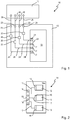
- Fig. 1 10 generally designates a schematically illustrated system for carrying out tests on biological sample material, which consists of various elements.
- the system 10 comprises, as the first element, a control unit 11, with which different connection plates 12 can optionally be connected as second elements, to which different microfluidic sample chips 14 can be coupled as third elements via a mechanical holding device 13, for which in FIG Fig. 2 an embodiment is shown.
- the receiving device 13 is used for the reliable anchoring of the sample chips 14 and their contacting. Furthermore, it enables an optical analysis of biological sample material, which can be assembled, cultivated, incubated and perfused on the sample chips 14. For this purpose, an optical analysis by means of transmitted light microscopy or at least by means of incident light microscopy is possible.
- the sample chip 14 out Fig. 2 comprises a carrier substrate 14a on which, for example, three microfluidic sample channel units 15 are formed, each of which has its own connection area 16 for media and signals.
- each sample chip 14 contains a sample channel unit 15.
- connection area 16 is connected in particular via connection lines 17 for media and signals to chip connection elements 18, which are arranged in a linear array 19 in the exemplary embodiment shown.
- connection elements 18 cooperate with inner connection elements 21 of the connection plate 12, which on the mechanical receiving area 13 of FIG Fig. 1 Connection plate 12 shown are provided.
- the inner connection elements 21 are also arranged here as a linear array 22.
- connection elements 18 also serve in particular the bubble-free connection of the sample chip 14 to the connection plate 12.
- the inner connection elements 21 are connected to outer connection elements 23 of the connection plate 12 via connection lines 24 for media and signals.
- the outer connection elements 23 are also used in particular for the bubble-free coupling of the connection plate 12 to the control unit 11.
- functional elements 25 are provided, which serve to influence the media and the signals that are exchanged between the sample channel units 15 and the outer connection elements 23 in a manner to be described.
- Functional elements 25 can also be designed to detect measurement signals.
- the outer connection elements 23 are detachably connected to the control unit 11 via further connection lines 26 for media and signals.
- control unit 11 is, for example, a dielectrophoresis unit, which is used to arrange biological sample material, in particular organotypical cell arrangements, in the sample channel units 15, as is the case in principle for the laboratory area of the DE 10 2008 018 170 B4 is known.
- the dielectrophoresis unit can be exchanged for a perfusion unit, which now serves as a control unit 11 and serves to supply the sample material with medium and to supply test substances during the incubation of the sample material in the sample channel units 15. Furthermore, measurement signals and liquid measurement samples are taken via the perfusion unit.
- the functional elements 25 also serve to process and forward media and signals that are exchanged between the control unit 11 and the connection areas 16 on the sample chips 14. These include, for example, the electrical and optical processing, distribution and merging as well as intermediate storage of control and measurement signals, the storage, transport and distribution of liquids and gases, the separation of gas components from the liquids in active or passive bubble traps, the transmission of pressure signals.
- the functional elements 25 can be designed as valves, multiplexers, pumps, heating systems, cooling systems,
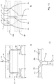
- FIG Fig. 3 The basic structure of a sample channel unit 15 formed on the carrier substrate 14a is shown in FIG Fig. 3 shown schematically, simplified and not to scale.
- the carrier substrate 14a consists entirely or at least in the area of a microfluidic sample arrangement area 31 within the sample channel unit 15 of optically thin material, for example of polycarbonate (PC), cycloolefin copolymer (COC), polymethyl methacrylate (PMMA), polydimethylsolixane (PDMS), or of glass or pure silicon.
- the carrier substrate 14 can be produced by molding, reshaping, lithographic processes, adding or removing material or material components.
- the sample arrangement area 31 has webs 32, 33 which delimit a gap 34 in which sample material 35 is collected.
- electrodes 36, 37 are provided, by means of which cells or other sample material are concentrated in the gap 34, which are guided into the sample arrangement area 31 via microfluidic supply channels 38.
- Microfluidic discharge channels 39 are provided opposite the feed channels 38, through which the flushed medium and any liquid measurement samples that may have been taken are discharged.
- a sample arrangement area 31 can be connected to one feed channel 38 and one discharge channel 39, or to several feed channels 38 and one discharge channel 39.
- the feed channels 38 are connected to a microfluidic functional area 41 and the discharge channels 39 to a microfluidic functional area 42.
- These functional areas 41, 42 include, for example, valve arrangements and branching structures in order to ensure a uniform distribution and / or a selectively controlled flow of the liquid media.
- valve arrangements and branching structures in order to ensure a uniform distribution and / or a selectively controlled flow of the liquid media.
- capillary stop valves are provided for the control of liquid media and check valves are provided for the control of gaseous media.
- the functional areas 41 and 42 are provided with the connection area 16 via microfluidic channels 43 and 44.
- the channels 43 and 44 can comprise a plurality of parallel microfluidic channels which run fluidically separate from one another, so that different media, in particular gases, substances and liquids, can be conducted into the sample arrangement area 31 via the connection area 16 and can be removed therefrom.
- connection area 16 contains connection elements, not shown, which serve for the supply / discharge of liquid media, for example for transporting the biological sample or substances to be tested, and gaseous substances, for example process gases and aerosols.
- connection elements can also include pipetting openings for gravity-driven flow, which are operated by pipetting systems.
- connection area 16 there are furthermore connection elements for the transmission of electrical signals and for optical signals or membranes transported via optical fibers for the transmission of pressure or acoustic vibrations.
- a functional unit 45 is also provided in the channel 43, which can be a bubble trap, for example, and ensures that no gas bubbles can get into the sample arrangement area 31 because these would hinder the distribution of liquid medium there.
- the bubble trap 45 separates gaseous components from the supplied media stream. It can be designed as an active element with vacuum-assisted suction with or without a blocking agent and as a purely passive element with special membranes.
- the electrodes 36 and 37 are connected via electrical lines 46 and 47 to electrical functional areas 48 and 49, which are each connected to the connection area 16 via electrical single or multiple lines 51 and 52.
- the electrical functional areas 48 and 49 are used for the actively controlled or passive distribution and collection of electrical signals.
- Various optically sensitive, electrical, electrochemical or biosensory functional elements 53, 54 and 55 are also provided in the sample channel unit 15 or the sample arrangement area 31, via which optically sensitive, electrical or chemical signals for checking, control or measurement value acquisition are interrogated and provided at the connection area 16 become.
- This local sensor system in the sample arrangement area 31 and in the sample channel unit 15 makes it possible to obtain measured values for statements about the vitality of cells that have been flushed into the sample channel unit 15 and / or assembled in the sample arrangement area 31.
- integrated sensors 53, 54, 55 are used, for example, with which, for example, the O 2 / CO 2 ion concentration, the pH value, impedances or metabolism products can be measured.
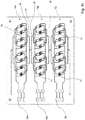
- Fig. 4a shows the basic structure of a sample channel unit 15, in which a total of eight sample arrangement areas 31 are connected fluidically and electrically in parallel are. For this purpose, a microfluidic feed channel 43 is divided several times with the aid of distribution points 56.
- microfluidic discharge channel 44 is fluidly connected to the sample arrangement areas 31 via combination points 57.
- Fig. 4a the electrodes 36 and 37 of the individual sample arrangement regions 31 can also be seen, which are connected electrically in parallel and are controlled via common connection elements 58.
- Fig. 4a is the top cover which rests on the carrier substrate 14a of the sample chip 14 and covers the microstructures which are open at the top. How such a capped microfluidic system can be produced is mentioned in the introduction DE 10 2008 018 170 A1 described, the content of which is hereby incorporated by reference. Below shows Fig. 11a a cross-sectional view through a sample chip 14, in which the carrier substrate 14a and a manhole cover 14b can be seen.
- This cover 14b is at least partially optically thin, so that the sample material in the sample arrangement area can be analyzed using optical methods.
- Fig. 5 shows an enlarged top view of a sample arrangement area 31, which consists of several webs 61 and microfluidic channels 62, which are arranged between the electrodes 36, 37 and are connected to one another via openings 63.
- the webs 61 and the openings 63 are examples of the webs 32, 33 and the gap 34 Fig. 3 ; see also Fig. 8c ,
- the sample arrangement area 31 is a specially shaped area of the sample channel unit 15, in which the biological sample material 35, in particular biological cells and cell components, can be arranged in a targeted manner under the influence of external forces, in particular electrical field strength or flow conditions.
- Openings 63 are provided between the webs 61, in which biological sample material can be assembled under the action of electrical fields generated by the electrodes 36, 37, as mentioned in the introduction DE 10 2008 018 170 B4 such as DE 10 2009 039 956 A1 is described.
- the effect of the electric field applied between the electrodes 36, 37 can be manipulated in such a way that the field strength in the area of the openings 63 is selectively increased or weakened in order to influence the assembly of the biological sample material 35 ,
- the surfaces of the webs 61 and channels 62 can be modified in a targeted manner in order to create an environment corresponding to the natural environmental conditions for the respective biological sample. These modifications can include hydrophilization or hydrophobization of the surfaces in question.
- the flow velocity is also influenced by the geometry of the webs 61 and channels 62 in order to support the assembly of the biological sample.
- Cross-sectional expansions in the channels 62 can, for example, create areas with reduced flow.
- the electrodes 36, 37 are particularly structured, conductive surfaces which, on the one hand, create electrical fields by influencing electrical direct and / or alternating voltages to influence the assembly of the biological sample material.
- the current flow measured when electrical direct and / or alternating voltages are applied allows conclusions to be drawn about the impedance of substances in the sample arrangement area 31, so that the electrodes 36, 37 also act as sensors. Furthermore, electrical pulses can be generated via the electrodes 36, 37, with which the cells assembled in the sample arrangement area can be disrupted.
- sample material with different substances can be tested in a sample channel unit 15.
- different biological sample material can be assembled in the different sample channel units 15 and tested with the same substance that is supplied through the supply channel 38.
- Fig. 4b shows a sample chip 14 on which 3 sample channel units 15a, 15b and 15c are connected in series to one another.
- Fig. 6 shows a perspective top view of an exemplary embodiment of the connection plate 12 Fig. 1 ,
- a sample chip 14 can be seen in the receiving area 13, on which an optically thin cover plate or cover film 64 rests, which, together with the sample chip 14, is clamped onto a carrier 67 of the connection plate 12 via clamping elements 65, 66.
- a fluidic block 68 serving for the fluidic connection, which in the present case has an inflow element 69 communicating with the inflow channel 43 and one with the in FIG Fig. 6 Discharge channel 44, which cannot be seen, comprises communicating drain element 70.
- connection plate 12 On the left outside of the connection plate 12, electrical connection elements 71 can be seen, which communicate with the lines 46, 47.
- the elements 69, 70, 71 are outer connection elements 23 of the connection plate 12.
- Fig. 7 shows a longitudinal section through the fluidic block 68 of the connection plate 12 Fig. 6 , from which the fluidic contacting of the sample chip 14 results.
- the fluidic block 68 serves to accommodate sealing elements and connection channels.
- it is made of polycarbonate or polymethyl methacrylate.
- 72 denotes a vertical connector on the sample chip 14, which is designed as a connecting olive
- 73 denotes a channel structure which serves to connect to the external connector and is surrounded at the end by a sealing element 74 which serves to connect inlet and outlet elements 69, 70 and as a screw or clamp connection can be formed.
- a comparable sealing element 75 is assigned to the vertical connection 72, which establishes the connection to the channel structures 76 on the sample chip side, which is formed, for example, by the supply channels 38 and discharge channels 39.
- the element 75 corresponds to one of the in Fig. 1 shown inner connection elements 21 of the connection plate 12.
- the elements 72, 76 are an example of the in Fig. 2 Connection elements 18 of the sample chip 14 shown.
- electrodes 36 and 37 may be gold electrodes
- the polymer electrodes are formed by introducing polymerizing monomers into corresponding microchannels, as described, for example, in detail in the not previously published DE 10 2012 102 321 is described.
- the electrodes are designed as a solid electrolyte which comprises a polymer matrix which is produced by polymerizing a monomer solution, which has at least one monomer, possibly at least one crosslinker, and at least one directly polymerizable ionic liquid which has an organic charge carrier, preferably an organic cation, and an inorganic counter-charge carrier, preferably an inorganic anion, the organic cation preferably having at least one allyl Rest, more preferably has at least one quaternary nitrogen.
- a directly polymerizable ionic liquid is understood to mean an ionic liquid which can be used without prior derivatization of the organic charge carrier.
- a monomer solution is used to produce the electrodes, in which three monomers are initially present in an organic solution, for example isopropanol.
- the monomer solution consists of a simple acrylate (simple chains) which, when polymerized alone, gives linear chains and represents the basic structure of the polymer (here: HEMA - 2-hydroxyethyl 2-methylprop-2-enoate).
- HEMA simple acrylate
- bisacrylate here: EGDMA - 2- (2-methyl-acryloyloxy) ethyl-2-methyl-acrylate
- the last monomer is an unsaturated ionic liquid (here: AlMeImCl - 1-allyl-3-methylimidazolium chloride) is added. This consists of chloride ions and a large, positively charged organic cation.
- the monomers are polymerized to a ter-polymer by a controlled free radical polymerization using a UV initiator (here: Irgacure2959-2-hydroxy-4 '- (2-hydroxyethoxy) -2-methylpropiophenone).
- an electrically conductive monomer solution into the microchannels 77, 78, 79 and allow it to harden as an electrode polymer.
- Fig. 8a shows a schematic plan view of a sample arrangement area 31 with webs 32, 33 and gap 34 as well as microfluidic feed channel 38 and discharge channel 39.
- 77 denotes inlet openings for the electrode polymer, that communicate with lead channels 78 that lead to patterning areas 79 in which the polymer electrodes are formed.
- Fig. 8b shows a representation like Fig. 8a , but with microchannels 77, 78, 79 filled with electrode polymer.
- Fig. 8c shows a sectional view along the line AA Fig. 8b , in which vertical capillary stops 80 for the electrode polymer can be seen.
- the capillary stops 80 serve to guide the filled-in electrode polymer along the structuring area 79, so that the electrode polymer cannot get into the sample arrangement area 31.
- Fig. 9 an example of a sample chip 14 is shown in detail, in which the microfluidic channels 38, 39 were produced together with the microchannels 77, 78, 79 and the remaining microstructuring in an injection molding production step.
- Fig. 10 shows examples of different valve systems and distribution points, via which it is ensured that all microfluidic channels 43, 44 are located in the in Fig. 4 Fill the sample channel unit 15 shown with liquid.
- microfluidic sample chips 14 made of hydrophobic materials with several branching microchannels 43, 44 the uniform filling of all microchannels 43, 44 often poses a problem due to the high surface tension; please refer Fig. 10a , Especially when the microchannels 44 are brought together again, air bubbles can be included which can hardly be removed.
- a cascade 83 consists of one or more multiplexers ( Fig. 10a ), at which the microchannels 43 are separated by means of the division points 56.
- a splitting point 56 divides an incoming liquid flow at its phase boundary into two new phase boundaries without, however, being subject to abrupt pressure changes.
- Figure 10a shows a possible embodiment of such a functional area.
- Cascaded capillary stop valves ( Fig. 10b ) for uniform filling of the microchannels 43, 44 and the sample arrangement areas 31.
- a liquid flow with its phase boundary first stops at a capillary stop valve of a first cascade stage 84a which contains flow obstacles 84b at which the microchannels 43 are brought together. Only when liquid flows from all microchannels 43 of a sample receiving area are present at the capillary stop valves of the first cascade stage, the burst pressure is exceeded and the menisci of the individual phase boundaries are brought together. This process is repeated for the subsequent cascade stages until the liquid flows of all sample areas are applied to the last cascade stage 84n.
- One or more merger valves ( Fig. 10c ) or cascades of merger valves are provided, on which the microchannels 44a, 44b are brought together again.
- Valves that can be used are described, for example, in EP 1 441 131 A1 and US 6,601,613 B2 ,
- Fig. 11 shows examples to ensure bubble-free filling of the microfluidic channels 43.
- Fig. 11a 45 denotes a functional unit designed as a bubble trap.
- Fig. 11a furthermore denotes the carrier substrate and 14b the channel cover for a microchannel 43.
- At least one bubble trap 45 can be connected upstream of the actual fluidics. This can be integrated directly into the sample chip 14 or into the connection plate 12, as is exemplified in FIG Fig. 11a and 11c is shown.
- a gas permeable membrane 87 is provided which is embedded in the manhole cover 14b.
- air bubbles 88 are intercepted from the duct 43 and the gas 89 escapes through the membrane 87.
- This embodiment is a purely passive bubble trap. If an additional vacuum suction is used, it is an active bubble trap.
- control unit 11 either a dielectrophoresis unit or a perfusion unit is used as control unit 11. While it only takes a few minutes to collect the cell culture, the cells should be cultivated over several weeks. If both are carried out with the same control unit 11, it is blocked for several weeks before cells can be reassembled.
- the dielectrophoresis unit controls the priming of the chip, the accumulation of cells by means of dielectrophoresis and the structure of the cell culture.
- the perfusion unit then ensures that the cell culture is supplied with medium and regulates the incubation with test substances over the culture period from days to weeks.
- connection plate 12 The contacting of the sample chip 14 to the two control units 11 takes place via the connection plate 12 and must allow the bubble-free and contamination-free coupling, that is to say the coupling and later re-coupling of the sample chip from one control unit to the other.
- These manipulations practically inevitably lead to the penetration of air bubbles 88 from the outer connection elements 23 of the connection plate 12 into the sample chip 14; please refer Fig. 12 , However, these air bubbles disrupt the flow, for example by changing the flow resistance in the affected channel segment, and destroy the cell culture when they reach the sample arrangement areas.
- the contact can be made according to Fig. 11b via a septum 91 on the sample chip 14 or the connecting plate 12, the connection to the control unit 11 being established by a hollow needle 90.
- the hollow needle 90 can be part of the control unit 11 but also part of the connection plate 12.
- the air bubble-free coupling is preferably carried out using a microfluidic ventilation device according to Fig. 11a expanded by a septum 91 according to Fig. 11b how it combined in Fig. 11c is shown.
- Air bubbles 88 penetrating into the microchannels 43 via the hollow needle 90 during coupling or decoupling are discharged again in the downstream bubble trap via the membrane 87.
- the septum 91 can be protected from contamination, preferably by a blister film 92 which at least partially covers the septum 91.
- connection plate 12 can be coupled to the control units 11 via inlet elements 69 and outlet elements 70 as combinations of hose and screw connections. Degassing takes place as already mentioned above.
- connection plate is preferably coupled via a plug-in system as exemplified in FIG Fig. 12 is shown, in which the coupling of the sample chip can be carried out completely without hose material.
- Fig. 12 is a sectional view of the coupling of a sample chip 14 clamped on a connection plate 12 to a control unit 11 via the Fig. 7 known fluidic block 68 and outer connection elements 23 shown.
- the sealing element 74 is seated here in the control unit 11, a connection element 23 is sealed in this sealing element 74.
- the fluidic block 68 is connected to the sample chip 14 as in FIG Fig. 7 , the vent as in Fig. 11a ,
- the integration of the functional elements 41, 42, 45, 48, 49, 53, 54, 55 in the individual sample channel units 15 enables monitoring of various parameters, such as electrode function, filling and air bubble freedom of the sample chip 14, flow rates, temperature, gas content of the media, density cell culture and cell count etc. without the need for optical monitoring and manual steps.
- Suitable measuring principles for this are, for example, the impedance measurement for flow rates, air bubbles, cell density and control of the cell assembly, as well as optical / electrochemical O 2 / CO 2 sensors, temperature sensors and strain gauges for the detection of flow rates and air bubbles.
- optoelectronic sensors or micro-optical or optofluidic methods can be used, as is described, for example, in US Pat US 2011/0181884 A1 ,
- Impedance measurements can also be carried out via the electrodes 36 and 37.
- the functional elements 41, 42, 45, 48, 49, 53, 54, 55 described so far are used for quality assurance, that is to say the functionality of the sample chip 14, the monitoring of the cell density and, above all, the calibration of the entire system.
- the functional elements can also be used to measure the cell reaction, that is to say, for example, to measure the vitality or the activity when chemical substances or medications are supplied.
- the integrated sensors that is to say the functional elements 53, 54, 55, allow a less complex and therefore cheaper and, above all, continuous measurement of the cell reactions.
- the cell vitality can be determined, for example, by measuring the oxygen content in the medium before and after the medium has passed the sample arrangement areas 31.
- Measurements of the impedance of the cell arrangement in the sample arrangement area 31 provide, for example, information about the tightness of tissue barriers, as can be found, for example, in the blood-brain barrier, in the intestine or in the kidney.
- the continuous measurements of ion concentration, pH value or of products of cell metabolism in the medium carried out directly on the sample chip 14, that is to say on-line, provide direct information about the functionality of the cells without the medium behind the sample chip 14 being collected and analyzed got to. These measurements can be carried out electrochemically or with the aid of biosensors that use immobilized antibodies and / or enzymes.
- asymmetrical tissue structures such as endothelial barriers of the intestine or the blood-brain barrier
- a separating structure 94 which can be designed as a hydrogel 97.
- the hydrogel may be located between posts 96 provided in the gap 34, as shown in FIG Fig. 13 is shown where the hydrogel corresponds to gap 34 and posts 96 13a partially or according to Fig. 13b completely covered.
- Hydrogels that can be used are, for example, in US Pat DE 10 2007 034 580 A1 and the DE 10 2007 051 059 A1 described, so that reference is made to these publications for further information.
- asymmetrical structures are created by assembling different cell types on different sides of the hydrogel.
- e.g. Endothelial cells and other astrocytes are established.
- the hydrogels have crosslinks, for example, which can be cut by metalloproteases.
- the use of alginate gels is also contemplated, which can be dissolved by adding Ca 2+ complexing substances such as EDT or citrate.
- Another way of building asymmetrical structures is to connect two separate channels by a microcapillary array, as is already the case in principle DE 10 2008 018 170 B4 is described.
- Such an array of Micro-openings created a dielectrophoretic field, so only one of the channels flushed cells are accumulated, so that an asymmetrical cell structure can be realized.
- an insulating membrane 95 with holes 95a can also be used as a separating structure 94 between the microchannels 38, 39, as shown in FIG Fig. 14 is shown.
- the cells are drawn through the dielectrophoretic field into or onto the holes 95a in the membrane, since these holes 95a also produce local field inhomogeneities 96 and thus dielectrophoretic forces when a voltage is applied, as is shown in FIG Fig. 14 It can be seen that shows an exemplary embodiment for the accumulation of complex cell arrangements in a sample arrangement area 31.
- Such organ structures can only be realized by the series connection of two or more sample arrangement areas, which can be individually and selectively electrically addressed.
- These sample arrangement areas can either have the same or different microstructures for the formation of the dielectrophoretic field and can position cells in the arrangement suitable for the respective substructure.
- cells for the first sample arrangement area 31 are rinsed into the sample chip 14 and only this first sample arrangement area 31 is provided with a dielectrophoresis voltage in order to assemble the cells.
- the cells for the second sample arrangement area 31 are then washed in, the dielectrophoretic field is only applied to this second sample arrangement area 31, and the second substructure is assembled.
- the following organ and tissue models can be established: endothelial / epithelial layers and barriers for the blood-brain barrier, the kidney, the intestine and the lungs; 3D tissue of tumors, metastasis models in the liver and intestine and thyroid. Furthermore, the differentiation of stem cells can be established and monitored.
- control unit 11 and the connection plate 12 are reusable, while the sample chips 14 are generally consumables.
- the sample chips 14 can be provided in a kit together with other materials in order to prepare them for certain applications.
- the advantage of such a kit is that all the materials required are provided together with the microfluidic sample chip 14 as an economic unit, so that compliance with the required standards and the purity of the substances is ensured.
- the components of the kit include 14 media, reagents, buffers and possibly also cells for the following applications:
- Determination of the cell vitality on the sample chip Determination of the cell vitality on the sample chip, extraction of nucleic acid of the cultured cells from the sample chip, calibration of the cell culture, cleaning of the sample chip after the end of the experiment, introduction of protein coatings and / or hydrogels into the sample chip, assembly of cells, dispatch of precultivated sample chips.
- optical e.g. transmitted light, fluorescence, Raman, SERS, FIB / SEM
- electrical impedance, electrochemical sensors
- biochemical analysis of the perfundate e.g. using HPLC / MS
- the cells have to be lysed and DNA / RNA extracted from the sample chip, whereupon the nucleic acids are then further analyzed using suitable analytical methods such as microarrays, bead arrays, PCR or sequencing methods and mass spectrometric methods.
- suitable analytical methods such as microarrays, bead arrays, PCR or sequencing methods and mass spectrometric methods.
- the aim of this assay is, on the one hand, to extract the DNA in order to investigate genetic features / changes in the cells, for example mutations in tumor cells or cell lines.
- statements about the up or down regulation of genes can be made by determining the amount and type of RNA in the cells.
- These assays are used, for example, to examine the reaction of the cells to certain substances.
- the cells are broken down either chemically via suitable substances or electrically via electrodes integrated in the sample chip.
- the cell components are then rinsed out of the sample chip and the nucleic acids can be duplicated and / or analyzed using standard methods.
- the sample chip offers the advantage that only very small amounts of reagents are required for cell disruption, or that reagents can even be completely dispensed with if the cells are applied to the ones already present in the sample chip by applying a low-frequency voltage ( ⁇ 100 kHz) Electrodes are lysed.
- metabolic enzyme activity in cells is intended.
- these would be, for example, cytochrome P450 enzymes (CYP), which mainly catalyze the metabolism of foreign substances such as medication in the body.
- CYP cytochrome P450 enzymes
- these are oxidation reactions in which oxygen atoms are integrated into the metabolized substance.
- the enzyme activity in the cells is determined by determining the concentration of cell products (e.g. albumin in liver cells) directly in the perfundate or by measuring the conversion of an enzyme substrate by the cells.
- the cells are incubated with substrates of the enzymes to be examined (eg testosterone to determine the CYP 3A4 activity of liver cells), the perfundate is collected and the concentration of the breakdown products in the perfundate is determined (eg 6 ⁇ -hydroxytestosterone which is formed by CYP3A4 from testosterone)
- the detection of the cell products can e.g. using immunoassays (e.g. enzyme-linked immunosorbent assays to quantify the albumin concentration) or using chromatography (e.g. high or ultra performance liquid chromatography HPLC, UPLC) or mass spectroscopy.
- the aim of this assay is to monitor the metabolic function of cells involved in the metabolism, such as the liver cells, in order to be able to detect any changes in response to substances supplied.
- 15a and 15b each show, as exemplary applications, results from experiments carried out with the sample chip on the decline in the albumin synthesis rate and the CYP3A4 activity in an organ-like liver cell culture, which were incubated with high concentrations of active substance.
- the incubation days are shown on the abscissa.
- 15a shows measurements of the albumin concentration from 3 different experiments with human or mouse hepatocytes. The cells became permanent incubated with 200 ⁇ M phenacetin, 200 ⁇ M testosterone and 100 ⁇ M 7-hydroxycoumarin at a flow rate of 3 ⁇ l / min.
- 15b shows measurements of the 6 ⁇ -hydroxytestosterone concentration in an experiment with human hepatocytes.
- the cells were incubated permanently with 200 ⁇ M phenacetin, 200 ⁇ M testosterone and 100 ⁇ M 7-hydroxycoumarin at a flow rate of 3 ⁇ l / min.
- This measurement reflects the activity of the cytochrome P450 3A4 enzyme, which catalyzes the conversion of testosterone into 6 ⁇ -hydroxytestosterone.
- the sample chip has the advantage that only small amounts of reagents have to be used.
- the concentration of substrate on the cells is kept almost constant through continuous perfusion, while the metabolic products are continuously removed via the media flow, similar to how they are in the body. So there can be no saturation of product, which would affect the cell activity unnaturally.
- This assay is concerned with the determination of toxicity, for example with repeated dosing, and the determination of dose-time profiles, for which purpose the cells are incubated with test substances which are supplied at defined time intervals and concentrations.
- the cell vitality, cell activity and changes in cell content - such as changes in the genome or proteome - are determined over time.
- the aim of this assay is to identify long-term effects in toxicity studies with repeated incubation, which can arise from the repeated use of substances. In this way, both short-term acute and chronic toxicity effects that may occur through long-term incubation can be measured.
- the cells are alternately incubated over a longer period of time with the substances to be examined (induction phase) and pure cell culture medium (recovery phase), the cell reaction, in particular its vitality and activity, being monitored. Both the concentrations and the incubation period of the substances can be varied.
- Carrying out this assay with a sample chip offers the advantage that, because of the use of the perfused sample chip, substances can be applied continuously in constant concentrations or with defined concentration profiles. This makes it possible for the first time to include the pharmacokinetic parameters of an active ingredient in the experiment and thus to investigate its toxicity in an experimental situation that comes close to the in vivo situation.
- the drug intake and the concentration profile in the organs can be simulated in the assay.
- Concentration profiles for the active ingredients and other substances can be programmed and controlled in the perfusion unit.
- the incubation period, flow rate and duration of the recovery phase can also be programmed and controlled via the perfusion unit. This method also allows analytes in the perfusate to be measured over time and correlated with the substance concentration profile.
- the cell barrier is established on the sample chip and incubated with the respective test substance, the perfundates of the sample chip are collected and the substance concentration in the perfundate in front of and behind the barrier is determined.
- a substance can be checked whether a substance is harmless because it does not pass through the membrane.
- the penetration or non-penetration of environmental toxins in chemical or particulate form e.g. nanoparticles
- new dosage forms for active substances can be tested.
- cell barriers are built up in the sample chip and incubated with substances.
- concentration of the substance in front of and behind the barrier is measured in order to check the accessibility. It can also be tested whether certain substances make the barrier more permeable and thus possibly have a harmful effect on an organism.
- the sample chip has the advantage over static models that it reproduces the natural flow situation in the body, where substances in the blood stream flow past the barrier and not - as in a static cell culture - act on the barrier in a standing liquid.
- Proteins can be stained with antibodies and staining reagents on the sample chip for the purpose of immunohistochemistry.
- the cells in question are fixed on the sample chip, for example with alcohols such as methanol or ethanol, the intracellular water being displaced from the cells and being replaced by alcohol. In this way, the cells should be preserved.
- alcohols such as methanol or ethanol
- the cell membranes are then made permeable to antibodies and other substances by adding detergents.
- the antibody / staining reagents are then flushed in via the microfluidic channels 38 of the sample chip and the cells are thus incubated with this medium.
- Cells can also be prepared on the sample chip for investigations using invasive methods, for example for electron microscopy.
- All reagents are supplied via the microfluidic channels of the sample chip.
- the cells in the sample chip are fixed with methanol, for example.
- the cells are then dried, for example by replacing the water with ethanol, and incubated with a contrast agent such as osmium tetroxide.
- the cells are then embedded in a matrix. This differs depending on the subsequent examination method, for example paraffin is used for tissue sections and epoxy resin is used for electron microscopy.
- This embedding is done by flushing paraffin or epoxy resin through the microfluidic channels to the cells. To this embedding, the cover of the sample chip is removed, the cells embedded in the matrix are removed, cut and the sections examined accordingly.
- the initial functionality of the cells can be determined.
- one of the sample channel units 15 on the sample chip 14 is used as a reference channel.
- the function of the cells is monitored without the influence of the substances.
- defined parameters are checked before the other sample channel units 15 are put into operation. In addition to checking the cell vitality, these parameters depend on the type of organ culture; in a liver culture, for example, the albumin production is monitored, and in the blood-brain barrier the electrical impedance of the cell barrier is monitored.
- the cause of the toxic effects of substances should be determined.
- the cell culture is incubated with toxic substances and the effect of the substance on various cell functions is examined. This includes, for example, inhibiting enzymes, causing inflammatory reactions or destroying cell-cell interactions.
- the new system also enables the establishment of models for the investigation of tumor formation. After building up an organ culture from healthy cells, tumor cells, e.g. circulating tumor cells, washed in. The behavior of the tumor cells in the tissue culture is monitored by microscopic monitoring. For example, the penetration into the cell aggregate, the displacement of cells or the growth of the tumor can be monitored optically.
- tumor cells e.g. circulating tumor cells
- the electrodes in the sample arrangement area can be used to promote the penetration of the tumor cells into the organ culture, that is to say metastasis, by means of dielectrophoresis.
- the functionality of the cells can be monitored using the assay described under b) above.
- both the tumor and the healthy cells can be lysed and their components, ie essentially the proteins and nucleic acids, can be analyzed; see assay a) above.
- the reaction of the cells to the drug candidates is more similar to the real situation than was the case in previous models.
- the aim of this application is to investigate the penetration of pathogens, e.g. bacteria, viruses or parasites, into tissue.
- pathogens e.g. bacteria, viruses or parasites
- an organ / tissue culture is first established in the sample chip.
- the pathogens are then flushed in through the microfluidic channels and their behavior is monitored optically in the cell culture. For example, the penetration into the built-up tissue can be observed.
- it is examined whether the pathogens influence the functionality of the cells in culture.
- the vitality and the enzyme activity are checked.
- the penetration of pathogens into a tissue / organ can be continuously monitored in the sample chip.
- the response of the cells to the pathogens is more similar to the real situation than was the case in previous models.
- This application examines how the toxic effects change when several active substances are administered in parallel (drug-drug interaction).
- the cell culture is incubated with two or more active substances either simultaneously or sequentially and the vitality of the cells is monitored.
- the toxicity of substances is to be examined based on the passage behavior of active substances / substances across barriers (blood-brain barrier, intestine, kidney).
Landscapes
- Health & Medical Sciences (AREA)
- Chemical & Material Sciences (AREA)
- Life Sciences & Earth Sciences (AREA)
- General Health & Medical Sciences (AREA)
- Engineering & Computer Science (AREA)
- Analytical Chemistry (AREA)
- Clinical Laboratory Science (AREA)
- Biomedical Technology (AREA)
- Biochemistry (AREA)
- Wood Science & Technology (AREA)
- Organic Chemistry (AREA)
- Chemical Kinetics & Catalysis (AREA)
- Dispersion Chemistry (AREA)
- Zoology (AREA)
- Bioinformatics & Cheminformatics (AREA)
- Molecular Biology (AREA)
- Physics & Mathematics (AREA)
- General Physics & Mathematics (AREA)
- Pathology (AREA)
- Immunology (AREA)
- Biotechnology (AREA)
- Microbiology (AREA)
- Sustainable Development (AREA)
- General Engineering & Computer Science (AREA)
- Genetics & Genomics (AREA)
- Hematology (AREA)
- Apparatus Associated With Microorganisms And Enzymes (AREA)
Priority Applications (1)
| Application Number | Priority Date | Filing Date | Title |
|---|---|---|---|
| EP19188161.4A EP3584010A1 (fr) | 2012-07-30 | 2012-07-30 | Methode d'etude d'un et/ou avec un echantillon biologique |
Applications Claiming Priority (3)
| Application Number | Priority Date | Filing Date | Title |
|---|---|---|---|
| EP12743441.3A EP2879789B1 (fr) | 2012-07-30 | 2012-07-30 | System comprenant une plaque de connexion pour une puce microfluidique, la puce microfluidique et une unite de controle |
| PCT/EP2012/064890 WO2014019603A1 (fr) | 2012-07-30 | 2012-07-30 | Plaque de connexion pour puce de test microfluidique, puce de test microfluidique et procédé d'analyse au moyen d'une zone d'un agencement de test microfluidique |
| EP19188161.4A EP3584010A1 (fr) | 2012-07-30 | 2012-07-30 | Methode d'etude d'un et/ou avec un echantillon biologique |
Related Parent Applications (2)
| Application Number | Title | Priority Date | Filing Date |
|---|---|---|---|
| EP12743441.3A Division EP2879789B1 (fr) | 2012-07-30 | 2012-07-30 | System comprenant une plaque de connexion pour une puce microfluidique, la puce microfluidique et une unite de controle |
| EP12743441.3A Division-Into EP2879789B1 (fr) | 2012-07-30 | 2012-07-30 | System comprenant une plaque de connexion pour une puce microfluidique, la puce microfluidique et une unite de controle |
Publications (1)
| Publication Number | Publication Date |
|---|---|
| EP3584010A1 true EP3584010A1 (fr) | 2019-12-25 |
Family
ID=46614478
Family Applications (2)
| Application Number | Title | Priority Date | Filing Date |
|---|---|---|---|
| EP19188161.4A Withdrawn EP3584010A1 (fr) | 2012-07-30 | 2012-07-30 | Methode d'etude d'un et/ou avec un echantillon biologique |
| EP12743441.3A Active EP2879789B1 (fr) | 2012-07-30 | 2012-07-30 | System comprenant une plaque de connexion pour une puce microfluidique, la puce microfluidique et une unite de controle |
Family Applications After (1)
| Application Number | Title | Priority Date | Filing Date |
|---|---|---|---|
| EP12743441.3A Active EP2879789B1 (fr) | 2012-07-30 | 2012-07-30 | System comprenant une plaque de connexion pour une puce microfluidique, la puce microfluidique et une unite de controle |
Country Status (3)
| Country | Link |
|---|---|
| US (1) | US20150204763A1 (fr) |
| EP (2) | EP3584010A1 (fr) |
| WO (1) | WO2014019603A1 (fr) |
Families Citing this family (23)
| Publication number | Priority date | Publication date | Assignee | Title |
|---|---|---|---|---|
| GB0724736D0 (en) | 2007-12-19 | 2008-01-30 | Oxford Nanolabs Ltd | Formation of layers of amphiphilic molecules |
| GB201202519D0 (en) | 2012-02-13 | 2012-03-28 | Oxford Nanopore Tech Ltd | Apparatus for supporting an array of layers of amphiphilic molecules and method of forming an array of layers of amphiphilic molecules |
| GB201313121D0 (en) | 2013-07-23 | 2013-09-04 | Oxford Nanopore Tech Ltd | Array of volumes of polar medium |
| GB201418512D0 (en) * | 2014-10-17 | 2014-12-03 | Oxford Nanopore Tech Ltd | Electrical device with detachable components |
| CN105241871B (zh) * | 2015-10-26 | 2018-03-06 | 深圳华迈兴微医疗科技有限公司 | 一种用于全血样品检测的磁微粒化学发光微流控芯片 |
| GB201611770D0 (en) | 2016-07-06 | 2016-08-17 | Oxford Nanopore Tech | Microfluidic device |
| CN110035690A (zh) * | 2016-07-19 | 2019-07-19 | 外分泌腺系统公司 | 汗液电导率、容积出汗速率和皮肤电反应设备及应用 |
| DE102016117421A1 (de) | 2016-09-15 | 2018-03-15 | Medizinische Universität Wien | Verfahren zum Durchführen eines Allergietests, Verfahren zum Bestimmen einer Degranulation bei Zellen, Vorrichtung zum Durchführen eines Allergietestes und mikrofluidischer Chip |
| ES2667430B1 (es) * | 2016-10-05 | 2019-02-20 | Univ Zaragoza | Dispositivo conector para circuitos microfluidicos |
| DE102017004567A1 (de) * | 2017-05-11 | 2018-11-15 | Innome Gmbh | Gerät zur Analyse von biologischen Proben |
| IT201700093925A1 (it) * | 2017-08-16 | 2019-02-16 | 1Lab Sa | Un processo di industrializzazione affidabile e riproducibile di eliminazione di bolle d'aria per la produzione di un tessuto vascolare ingegnerizzato. |
| US11022603B2 (en) * | 2017-08-30 | 2021-06-01 | The Charles Stark Draper Laboratory, Inc. | Microfluidic tissue biopsy and immune response drug evaluation devices and systems |
| DE102017010815A1 (de) | 2017-11-22 | 2019-05-23 | Lonovation Gmbh | Vorrichtung und Verfahren für die parallele Handhabung, Beobachtung und Kontrolle von gewebeähnlichen Zellverbänden |
| GB2568895B (en) | 2017-11-29 | 2021-10-27 | Oxford Nanopore Tech Ltd | Microfluidic device |
| EP3514223A1 (fr) * | 2018-01-17 | 2019-07-24 | Eppendorf AG | Multicapteur pour un bioréacteur, bioréacteur, procédé de fabrication d'un multicapteur et de mesure de paramètres |
| CN108126772A (zh) * | 2018-02-06 | 2018-06-08 | 山东科技大学 | 一种可连续操作的超净工作台 |
| CN113574381A (zh) | 2019-03-12 | 2021-10-29 | 牛津纳米孔科技公司 | 纳米孔感测装置、组件和操作方法 |
| CN109999928B (zh) * | 2019-03-28 | 2021-04-30 | 上海中航光电子有限公司 | 微流控芯片及其驱动方法、分析装置 |
| CN110006881B (zh) * | 2019-04-01 | 2020-09-11 | 深圳大学 | 尿液中碘含量的检测试剂盒及尿液中碘含量的检测方法 |
| EP3976753A4 (fr) | 2019-05-28 | 2023-07-19 | Wuxi Biologics Ireland Limited | Système de culture cellulaire à perfusion intégré à spectroscopie raman permettant de surveiller et de commander automatiquement la culture cellulaire à perfusion |
| DE102019135557A1 (de) * | 2019-12-20 | 2021-06-24 | Biophotonics Diagnostics GmbH | Probenträger zur elektrischen manipulation von flüssigen proben und zur schwingungsspektroskopie an den proben |
| CN111718853B (zh) * | 2020-07-03 | 2022-08-02 | 中山大学 | 一种用于药物筛选的2d和3d一体化肿瘤器官培养芯片的制备方法 |
| CN112871229B (zh) * | 2021-01-21 | 2022-06-28 | 中国科学技术大学 | 一种用于水体介电泳细菌分选的芯片 |
Citations (11)
| Publication number | Priority date | Publication date | Assignee | Title |
|---|---|---|---|---|
| US6601613B2 (en) | 1998-10-13 | 2003-08-05 | Biomicro Systems, Inc. | Fluid circuit components based upon passive fluid dynamics |
| EP1441131A1 (fr) | 2003-01-23 | 2004-07-28 | Steag MicroParts GmbH | Commutateur microfluidique pour arrêter temporairement un courant de liquide |
| US20040259177A1 (en) * | 2003-05-06 | 2004-12-23 | Lowery Robert G. | Three dimensional cell cultures in a microscale fluid handling system |
| US20070037277A1 (en) * | 2001-04-25 | 2007-02-15 | Michael Shuler | Pharmacokinetic-based culture system with biological barriers |
| US20090023608A1 (en) * | 2005-07-07 | 2009-01-22 | The Regents Of The University Of California | Methods and apparatus for cell culture array |
| DE102007034580A1 (de) | 2007-07-13 | 2009-01-29 | NMI Naturwissenschaftliches und Medizinisches Institut an der Universität Tübingen | Biomaterial basierend auf einem hydrophilen polymeren Träger |
| DE102007051059A1 (de) | 2007-10-18 | 2009-04-30 | NMI Naturwissenschaftliches und Medizinisches Institut an der Universität Tübingen | Bioverbundmaterial für die kontrollierte Freisetzung von Wirkstoffen |
| DE102008018170A1 (de) | 2008-04-03 | 2009-10-08 | NMI Naturwissenschaftliches und Medizinisches Institut an der Universität Tübingen | Mikrofluidisches System und Verfahren zum Aufbau und zur anschließenden Kultivierung sowie nachfolgender Untersuchung von komplexen Zellanordnungen |
| DE102009039956A1 (de) | 2009-08-27 | 2011-03-10 | NMI Naturwissenschaftliches und Medizinisches Institut an der Universität Tübingen | Mikrofluidisches System und Verfahren zu dessen Herstellung |
| US20110181884A1 (en) | 2008-03-04 | 2011-07-28 | California Institute Of Technology | Optofluidic microscope device with photosensor array |
| DE102012102321A1 (de) | 2012-03-20 | 2013-09-26 | NMI Naturwissenschaftliches und Medizinisches Institut an der Universität Tübingen | Miniaturisierte ionenselektive Elektrode zweiter Art |
Family Cites Families (8)
| Publication number | Priority date | Publication date | Assignee | Title |
|---|---|---|---|---|
| DE19854096A1 (de) * | 1998-11-24 | 2000-05-25 | Merck Patent Gmbh | Anschlußträger für plattenförmige Mikrokomponenten |
| DE19917398C2 (de) * | 1999-04-16 | 2002-06-20 | Accoris Gmbh | Modulares chemisches Mikrosystem |
| ATE544522T1 (de) * | 2006-10-25 | 2012-02-15 | Fraunhofer Ges Forschung | Chiphalter, fluidsystem und chiphaltersystem |
| US20110151479A1 (en) * | 2008-08-25 | 2011-06-23 | University Of Washington | Microfluidic systems incorporating flow-through membranes |
| US20100089135A1 (en) * | 2008-10-10 | 2010-04-15 | Nxp B.V. | Device and method for measuring sensor chips |
| EP2384243A4 (fr) * | 2009-01-30 | 2013-01-16 | Bio Rad Laboratories | Dispositif diélectrophorétique avec actionneur |
| EP2473857B1 (fr) * | 2009-09-01 | 2021-09-29 | Corsolutions, LLC | Interface microfluidique |
| WO2011147421A1 (fr) * | 2010-05-27 | 2011-12-01 | Danmarks Tekniske Universitet | Connecteur pour puce |
-
2012
- 2012-07-30 WO PCT/EP2012/064890 patent/WO2014019603A1/fr active Application Filing
- 2012-07-30 EP EP19188161.4A patent/EP3584010A1/fr not_active Withdrawn
- 2012-07-30 EP EP12743441.3A patent/EP2879789B1/fr active Active
-
2015
- 2015-01-29 US US14/609,369 patent/US20150204763A1/en not_active Abandoned
Patent Citations (12)
| Publication number | Priority date | Publication date | Assignee | Title |
|---|---|---|---|---|
| US6601613B2 (en) | 1998-10-13 | 2003-08-05 | Biomicro Systems, Inc. | Fluid circuit components based upon passive fluid dynamics |
| US20070037277A1 (en) * | 2001-04-25 | 2007-02-15 | Michael Shuler | Pharmacokinetic-based culture system with biological barriers |
| EP1441131A1 (fr) | 2003-01-23 | 2004-07-28 | Steag MicroParts GmbH | Commutateur microfluidique pour arrêter temporairement un courant de liquide |
| US20040259177A1 (en) * | 2003-05-06 | 2004-12-23 | Lowery Robert G. | Three dimensional cell cultures in a microscale fluid handling system |
| US20090023608A1 (en) * | 2005-07-07 | 2009-01-22 | The Regents Of The University Of California | Methods and apparatus for cell culture array |
| DE102007034580A1 (de) | 2007-07-13 | 2009-01-29 | NMI Naturwissenschaftliches und Medizinisches Institut an der Universität Tübingen | Biomaterial basierend auf einem hydrophilen polymeren Träger |
| DE102007051059A1 (de) | 2007-10-18 | 2009-04-30 | NMI Naturwissenschaftliches und Medizinisches Institut an der Universität Tübingen | Bioverbundmaterial für die kontrollierte Freisetzung von Wirkstoffen |
| US20110181884A1 (en) | 2008-03-04 | 2011-07-28 | California Institute Of Technology | Optofluidic microscope device with photosensor array |
| DE102008018170A1 (de) | 2008-04-03 | 2009-10-08 | NMI Naturwissenschaftliches und Medizinisches Institut an der Universität Tübingen | Mikrofluidisches System und Verfahren zum Aufbau und zur anschließenden Kultivierung sowie nachfolgender Untersuchung von komplexen Zellanordnungen |
| DE102008018170B4 (de) | 2008-04-03 | 2010-05-12 | NMI Naturwissenschaftliches und Medizinisches Institut an der Universität Tübingen | Mikrofluidisches System und Verfahren zum Aufbau und zur anschließenden Kultivierung sowie nachfolgender Untersuchung von komplexen Zellanordnungen |
| DE102009039956A1 (de) | 2009-08-27 | 2011-03-10 | NMI Naturwissenschaftliches und Medizinisches Institut an der Universität Tübingen | Mikrofluidisches System und Verfahren zu dessen Herstellung |
| DE102012102321A1 (de) | 2012-03-20 | 2013-09-26 | NMI Naturwissenschaftliches und Medizinisches Institut an der Universität Tübingen | Miniaturisierte ionenselektive Elektrode zweiter Art |
Non-Patent Citations (6)
| Title |
|---|
| FLUECKIGER J ET AL: "Integrated microfluidic systems for cell culture and characterization", MIXED-SIGNALS, SENSORS, AND SYSTEMS TEST WORKSHOP, 2008. IMS3TW 2008. IEEE 14TH INTERNATIONAL, IEEE, PISCATAWAY, NJ, USA, 18 June 2008 (2008-06-18), pages 1 - 6, XP031293668, ISBN: 978-1-4244-2395-8 * |
| HUA DONG ET AL: "Screen-printed microfluidic device for electrochemical immunoassay", LAB ON A CHIP, vol. 7, no. 12, 1 January 2007 (2007-01-01), pages 1752, XP055012342, ISSN: 1473-0197, DOI: 10.1039/b712394a * |
| JULIA SCHÜTTE ET AL: ""Artificial micro organs"-a microfluidic device for dielectrophoretic assembly of liver sinusoids", BIOMEDICAL MICRODEVICES, KLUWER ACADEMIC PUBLISHERS, BO, vol. 13, no. 3, 24 February 2011 (2011-02-24), pages 493 - 501, XP019897559, ISSN: 1572-8781, DOI: 10.1007/S10544-011-9517-7 * |
| LEE ET AL: "Microfluidic System for Automated Cell-Based Assays", JOURNAL OF THE ASSOCIATION FOR LABORATORY AUTOMATION, ELSEVIER, vol. 12, no. 6, 20 November 2007 (2007-11-20), pages 363 - 367, XP022346355, ISSN: 1535-5535, DOI: 10.1016/J.JALA.2007.07.001 * |
| W. MENZ ET AL.: "Microsystem Technology", 2001, WILEY-VCH VERLAG GMBH |
| WANG H Y ET AL: "A microfluidic flow-through device for high throughput electrical lysis of bacterial cells based on continuous dc voltage", BIOSENSORS AND BIOELECTRONICS, ELSEVIER BV, NL, vol. 22, no. 5, 15 December 2006 (2006-12-15), pages 582 - 588, XP024961538, ISSN: 0956-5663, [retrieved on 20061215], DOI: 10.1016/J.BIOS.2006.01.032 * |
Also Published As
| Publication number | Publication date |
|---|---|
| US20150204763A1 (en) | 2015-07-23 |
| WO2014019603A1 (fr) | 2014-02-06 |
| EP2879789A1 (fr) | 2015-06-10 |
| EP2879789B1 (fr) | 2019-09-04 |
Similar Documents
| Publication | Publication Date | Title |
|---|---|---|
| EP2879789B1 (fr) | System comprenant une plaque de connexion pour une puce microfluidique, la puce microfluidique et une unite de controle | |
| US8293524B2 (en) | Methods and apparatus for the manipulation of particle suspensions and testing thereof | |
| EP3380240B1 (fr) | Bioréacteurs micro-fluidiques empilables et superposés à compartiments multiples et leurs applications | |
| DE69909462T2 (de) | Mikrofabrizierte vorrichtung für analyse von zellen | |
| US10202569B2 (en) | Radial microfluidic devices and methods of use | |
| EP1741487B1 (fr) | Dispositif microfluidique de génération des gradients de diffusion et procédé correspondant | |
| KR101619167B1 (ko) | 세포의 시료감응성 측정을 위한 미세유체칩 | |
| WO2013116834A2 (fr) | Dispositif microfluidique permettant de générer des cellules neurales pour simuler les conditions d'accident vasculaire cérébral | |
| WO2010101708A2 (fr) | Dispositif microfluide et procédés apparentés | |
| DE102006033875A1 (de) | Analysesystem basierend auf porösem Material für hochparallele Einzelzelldetektion | |
| Li et al. | High-throughput single cell multidrug resistance analysis with multifunctional gradients-customizing microfluidic device | |
| WO2016005741A1 (fr) | Dispositif de positionnement de cellules et d'analyse | |
| WO2015169287A1 (fr) | Procédé et dispositifs pour la production in vitro d'ensembles de couches cellulaires | |
| DE102009039956A1 (de) | Mikrofluidisches System und Verfahren zu dessen Herstellung | |
| DE102011050254A1 (de) | Verfahren zur Separation polarisierbarer Biopartikel | |
| EP2184344B1 (fr) | Bioréacteur microfluidique | |
| Svendsen et al. | Micro and nano-platforms for biological cell analysis | |
| WO2008116244A1 (fr) | Dispositif, notamment biopuce, d'identification de micro-organismes | |
| DE102022123877B4 (de) | Grundkörper eines Mehrkammer-Biochips, Herstellung des Mehrkammer-Biochips und dessen Verwendung für die Etablierung von Organ- und Krankheitsmodellen und Substanztestungen | |
| DE10019833C2 (de) | Vorrichtung und Verfahren zur Simulation von Fluidströmungsverhältnissen | |
| Wei | Studying cell metabolism and cell interactions using microfluidic devices coupled with mass spectrometry |
Legal Events
| Date | Code | Title | Description |
|---|---|---|---|
| PUAI | Public reference made under article 153(3) epc to a published international application that has entered the european phase |
Free format text: ORIGINAL CODE: 0009012 |
|
| STAA | Information on the status of an ep patent application or granted ep patent |
Free format text: STATUS: THE APPLICATION HAS BEEN PUBLISHED |
|
| AC | Divisional application: reference to earlier application |
Ref document number: 2879789 Country of ref document: EP Kind code of ref document: P |
|
| AK | Designated contracting states |
Kind code of ref document: A1 Designated state(s): AL AT BE BG CH CY CZ DE DK EE ES FI FR GB GR HR HU IE IS IT LI LT LU LV MC MK MT NL NO PL PT RO RS SE SI SK SM TR |
|
| STAA | Information on the status of an ep patent application or granted ep patent |
Free format text: STATUS: REQUEST FOR EXAMINATION WAS MADE |
|
| 17P | Request for examination filed |
Effective date: 20200604 |
|
| RBV | Designated contracting states (corrected) |
Designated state(s): AL AT BE BG CH CY CZ DE DK EE ES FI FR GB GR HR HU IE IS IT LI LT LU LV MC MK MT NL NO PL PT RO RS SE SI SK SM TR |
|
| STAA | Information on the status of an ep patent application or granted ep patent |
Free format text: STATUS: EXAMINATION IS IN PROGRESS |
|
| 17Q | First examination report despatched |
Effective date: 20201217 |
|
| STAA | Information on the status of an ep patent application or granted ep patent |
Free format text: STATUS: THE APPLICATION IS DEEMED TO BE WITHDRAWN |
|
| 18D | Application deemed to be withdrawn |
Effective date: 20210429 |