EP3584003A1 - Mischer - Google Patents
Mischer Download PDFInfo
- Publication number
- EP3584003A1 EP3584003A1 EP19179913.9A EP19179913A EP3584003A1 EP 3584003 A1 EP3584003 A1 EP 3584003A1 EP 19179913 A EP19179913 A EP 19179913A EP 3584003 A1 EP3584003 A1 EP 3584003A1
- Authority
- EP
- European Patent Office
- Prior art keywords
- mixer
- exhaust gas
- mixer body
- receiving channel
- channel
- Prior art date
- Legal status (The legal status is an assumption and is not a legal conclusion. Google has not performed a legal analysis and makes no representation as to the accuracy of the status listed.)
- Granted
Links
Images


Classifications
-
- F—MECHANICAL ENGINEERING; LIGHTING; HEATING; WEAPONS; BLASTING
- F01—MACHINES OR ENGINES IN GENERAL; ENGINE PLANTS IN GENERAL; STEAM ENGINES
- F01N—GAS-FLOW SILENCERS OR EXHAUST APPARATUS FOR MACHINES OR ENGINES IN GENERAL; GAS-FLOW SILENCERS OR EXHAUST APPARATUS FOR INTERNAL-COMBUSTION ENGINES
- F01N3/00—Exhaust or silencing apparatus having means for purifying, rendering innocuous, or otherwise treating exhaust
- F01N3/08—Exhaust or silencing apparatus having means for purifying, rendering innocuous, or otherwise treating exhaust for rendering innocuous
- F01N3/10—Exhaust or silencing apparatus having means for purifying, rendering innocuous, or otherwise treating exhaust for rendering innocuous by thermal or catalytic conversion of noxious components of exhaust
- F01N3/18—Exhaust or silencing apparatus having means for purifying, rendering innocuous, or otherwise treating exhaust for rendering innocuous by thermal or catalytic conversion of noxious components of exhaust characterised by methods of operation; Control
- F01N3/20—Exhaust or silencing apparatus having means for purifying, rendering innocuous, or otherwise treating exhaust for rendering innocuous by thermal or catalytic conversion of noxious components of exhaust characterised by methods of operation; Control specially adapted for catalytic conversion
- F01N3/206—Adding periodically or continuously substances to exhaust gases for promoting purification, e.g. catalytic material in liquid form, NOx reducing agents
- F01N3/2066—Selective catalytic reduction [SCR]
-
- B—PERFORMING OPERATIONS; TRANSPORTING
- B01—PHYSICAL OR CHEMICAL PROCESSES OR APPARATUS IN GENERAL
- B01F—MIXING, e.g. DISSOLVING, EMULSIFYING OR DISPERSING
- B01F23/00—Mixing according to the phases to be mixed, e.g. dispersing or emulsifying
- B01F23/10—Mixing gases with gases
- B01F23/12—Mixing gases with gases with vaporisation of a liquid
-
- F—MECHANICAL ENGINEERING; LIGHTING; HEATING; WEAPONS; BLASTING
- F01—MACHINES OR ENGINES IN GENERAL; ENGINE PLANTS IN GENERAL; STEAM ENGINES
- F01N—GAS-FLOW SILENCERS OR EXHAUST APPARATUS FOR MACHINES OR ENGINES IN GENERAL; GAS-FLOW SILENCERS OR EXHAUST APPARATUS FOR INTERNAL-COMBUSTION ENGINES
- F01N3/00—Exhaust or silencing apparatus having means for purifying, rendering innocuous, or otherwise treating exhaust
- F01N3/08—Exhaust or silencing apparatus having means for purifying, rendering innocuous, or otherwise treating exhaust for rendering innocuous
- F01N3/10—Exhaust or silencing apparatus having means for purifying, rendering innocuous, or otherwise treating exhaust for rendering innocuous by thermal or catalytic conversion of noxious components of exhaust
- F01N3/18—Exhaust or silencing apparatus having means for purifying, rendering innocuous, or otherwise treating exhaust for rendering innocuous by thermal or catalytic conversion of noxious components of exhaust characterised by methods of operation; Control
- F01N3/20—Exhaust or silencing apparatus having means for purifying, rendering innocuous, or otherwise treating exhaust for rendering innocuous by thermal or catalytic conversion of noxious components of exhaust characterised by methods of operation; Control specially adapted for catalytic conversion
- F01N3/2006—Periodically heating or cooling catalytic reactors, e.g. at cold starting or overheating
- F01N3/2013—Periodically heating or cooling catalytic reactors, e.g. at cold starting or overheating using electric or magnetic heating means
-
- B—PERFORMING OPERATIONS; TRANSPORTING
- B01—PHYSICAL OR CHEMICAL PROCESSES OR APPARATUS IN GENERAL
- B01F—MIXING, e.g. DISSOLVING, EMULSIFYING OR DISPERSING
- B01F23/00—Mixing according to the phases to be mixed, e.g. dispersing or emulsifying
- B01F23/20—Mixing gases with liquids
- B01F23/21—Mixing gases with liquids by introducing liquids into gaseous media
- B01F23/213—Mixing gases with liquids by introducing liquids into gaseous media by spraying or atomising of the liquids
- B01F23/2132—Mixing gases with liquids by introducing liquids into gaseous media by spraying or atomising of the liquids using nozzles
-
- B—PERFORMING OPERATIONS; TRANSPORTING
- B01—PHYSICAL OR CHEMICAL PROCESSES OR APPARATUS IN GENERAL
- B01F—MIXING, e.g. DISSOLVING, EMULSIFYING OR DISPERSING
- B01F23/00—Mixing according to the phases to be mixed, e.g. dispersing or emulsifying
- B01F23/20—Mixing gases with liquids
- B01F23/23—Mixing gases with liquids by introducing gases into liquid media, e.g. for producing aerated liquids
- B01F23/231—Mixing gases with liquids by introducing gases into liquid media, e.g. for producing aerated liquids by bubbling
- B01F23/23105—Arrangement or manipulation of the gas bubbling devices
- B01F23/2312—Diffusers
-
- B—PERFORMING OPERATIONS; TRANSPORTING
- B01—PHYSICAL OR CHEMICAL PROCESSES OR APPARATUS IN GENERAL
- B01F—MIXING, e.g. DISSOLVING, EMULSIFYING OR DISPERSING
- B01F25/00—Flow mixers; Mixers for falling materials, e.g. solid particles
- B01F25/30—Injector mixers
- B01F25/31—Injector mixers in conduits or tubes through which the main component flows
- B01F25/313—Injector mixers in conduits or tubes through which the main component flows wherein additional components are introduced in the centre of the conduit
- B01F25/3131—Injector mixers in conduits or tubes through which the main component flows wherein additional components are introduced in the centre of the conduit with additional mixing means other than injector mixers, e.g. screens, baffles or rotating elements
-
- B—PERFORMING OPERATIONS; TRANSPORTING
- B01—PHYSICAL OR CHEMICAL PROCESSES OR APPARATUS IN GENERAL
- B01F—MIXING, e.g. DISSOLVING, EMULSIFYING OR DISPERSING
- B01F25/00—Flow mixers; Mixers for falling materials, e.g. solid particles
- B01F25/40—Static mixers
- B01F25/42—Static mixers in which the mixing is affected by moving the components jointly in changing directions, e.g. in tubes provided with baffles or obstructions
- B01F25/421—Static mixers in which the mixing is affected by moving the components jointly in changing directions, e.g. in tubes provided with baffles or obstructions by moving the components in a convoluted or labyrinthine path
- B01F25/423—Static mixers in which the mixing is affected by moving the components jointly in changing directions, e.g. in tubes provided with baffles or obstructions by moving the components in a convoluted or labyrinthine path by means of elements placed in the receptacle for moving or guiding the components
- B01F25/4231—Static mixers in which the mixing is affected by moving the components jointly in changing directions, e.g. in tubes provided with baffles or obstructions by moving the components in a convoluted or labyrinthine path by means of elements placed in the receptacle for moving or guiding the components using baffles
-
- B—PERFORMING OPERATIONS; TRANSPORTING
- B01—PHYSICAL OR CHEMICAL PROCESSES OR APPARATUS IN GENERAL
- B01F—MIXING, e.g. DISSOLVING, EMULSIFYING OR DISPERSING
- B01F25/00—Flow mixers; Mixers for falling materials, e.g. solid particles
- B01F25/40—Static mixers
- B01F25/42—Static mixers in which the mixing is affected by moving the components jointly in changing directions, e.g. in tubes provided with baffles or obstructions
- B01F25/421—Static mixers in which the mixing is affected by moving the components jointly in changing directions, e.g. in tubes provided with baffles or obstructions by moving the components in a convoluted or labyrinthine path
- B01F25/423—Static mixers in which the mixing is affected by moving the components jointly in changing directions, e.g. in tubes provided with baffles or obstructions by moving the components in a convoluted or labyrinthine path by means of elements placed in the receptacle for moving or guiding the components
- B01F25/4233—Static mixers in which the mixing is affected by moving the components jointly in changing directions, e.g. in tubes provided with baffles or obstructions by moving the components in a convoluted or labyrinthine path by means of elements placed in the receptacle for moving or guiding the components using plates with holes, the holes being displaced from one plate to the next one to force the flow to make a bending movement
-
- B—PERFORMING OPERATIONS; TRANSPORTING
- B01—PHYSICAL OR CHEMICAL PROCESSES OR APPARATUS IN GENERAL
- B01F—MIXING, e.g. DISSOLVING, EMULSIFYING OR DISPERSING
- B01F35/00—Accessories for mixers; Auxiliary operations or auxiliary devices; Parts or details of general application
- B01F35/90—Heating or cooling systems
- B01F35/93—Heating or cooling systems arranged inside the receptacle
-
- F—MECHANICAL ENGINEERING; LIGHTING; HEATING; WEAPONS; BLASTING
- F01—MACHINES OR ENGINES IN GENERAL; ENGINE PLANTS IN GENERAL; STEAM ENGINES
- F01N—GAS-FLOW SILENCERS OR EXHAUST APPARATUS FOR MACHINES OR ENGINES IN GENERAL; GAS-FLOW SILENCERS OR EXHAUST APPARATUS FOR INTERNAL-COMBUSTION ENGINES
- F01N3/00—Exhaust or silencing apparatus having means for purifying, rendering innocuous, or otherwise treating exhaust
- F01N3/08—Exhaust or silencing apparatus having means for purifying, rendering innocuous, or otherwise treating exhaust for rendering innocuous
- F01N3/10—Exhaust or silencing apparatus having means for purifying, rendering innocuous, or otherwise treating exhaust for rendering innocuous by thermal or catalytic conversion of noxious components of exhaust
- F01N3/18—Exhaust or silencing apparatus having means for purifying, rendering innocuous, or otherwise treating exhaust for rendering innocuous by thermal or catalytic conversion of noxious components of exhaust characterised by methods of operation; Control
- F01N3/20—Exhaust or silencing apparatus having means for purifying, rendering innocuous, or otherwise treating exhaust for rendering innocuous by thermal or catalytic conversion of noxious components of exhaust characterised by methods of operation; Control specially adapted for catalytic conversion
- F01N3/2006—Periodically heating or cooling catalytic reactors, e.g. at cold starting or overheating
-
- F—MECHANICAL ENGINEERING; LIGHTING; HEATING; WEAPONS; BLASTING
- F01—MACHINES OR ENGINES IN GENERAL; ENGINE PLANTS IN GENERAL; STEAM ENGINES
- F01N—GAS-FLOW SILENCERS OR EXHAUST APPARATUS FOR MACHINES OR ENGINES IN GENERAL; GAS-FLOW SILENCERS OR EXHAUST APPARATUS FOR INTERNAL-COMBUSTION ENGINES
- F01N3/00—Exhaust or silencing apparatus having means for purifying, rendering innocuous, or otherwise treating exhaust
- F01N3/08—Exhaust or silencing apparatus having means for purifying, rendering innocuous, or otherwise treating exhaust for rendering innocuous
- F01N3/10—Exhaust or silencing apparatus having means for purifying, rendering innocuous, or otherwise treating exhaust for rendering innocuous by thermal or catalytic conversion of noxious components of exhaust
- F01N3/24—Exhaust or silencing apparatus having means for purifying, rendering innocuous, or otherwise treating exhaust for rendering innocuous by thermal or catalytic conversion of noxious components of exhaust characterised by constructional aspects of converting apparatus
- F01N3/28—Construction of catalytic reactors
-
- F—MECHANICAL ENGINEERING; LIGHTING; HEATING; WEAPONS; BLASTING
- F01—MACHINES OR ENGINES IN GENERAL; ENGINE PLANTS IN GENERAL; STEAM ENGINES
- F01N—GAS-FLOW SILENCERS OR EXHAUST APPARATUS FOR MACHINES OR ENGINES IN GENERAL; GAS-FLOW SILENCERS OR EXHAUST APPARATUS FOR INTERNAL-COMBUSTION ENGINES
- F01N3/00—Exhaust or silencing apparatus having means for purifying, rendering innocuous, or otherwise treating exhaust
- F01N3/08—Exhaust or silencing apparatus having means for purifying, rendering innocuous, or otherwise treating exhaust for rendering innocuous
- F01N3/10—Exhaust or silencing apparatus having means for purifying, rendering innocuous, or otherwise treating exhaust for rendering innocuous by thermal or catalytic conversion of noxious components of exhaust
- F01N3/24—Exhaust or silencing apparatus having means for purifying, rendering innocuous, or otherwise treating exhaust for rendering innocuous by thermal or catalytic conversion of noxious components of exhaust characterised by constructional aspects of converting apparatus
- F01N3/28—Construction of catalytic reactors
- F01N3/2892—Exhaust flow directors or the like, e.g. upstream of catalytic device
-
- B—PERFORMING OPERATIONS; TRANSPORTING
- B01—PHYSICAL OR CHEMICAL PROCESSES OR APPARATUS IN GENERAL
- B01F—MIXING, e.g. DISSOLVING, EMULSIFYING OR DISPERSING
- B01F25/00—Flow mixers; Mixers for falling materials, e.g. solid particles
- B01F2025/93—Arrangements, nature or configuration of flow guiding elements
- B01F2025/931—Flow guiding elements surrounding feed openings, e.g. jet nozzles
-
- B—PERFORMING OPERATIONS; TRANSPORTING
- B01—PHYSICAL OR CHEMICAL PROCESSES OR APPARATUS IN GENERAL
- B01F—MIXING, e.g. DISSOLVING, EMULSIFYING OR DISPERSING
- B01F35/00—Accessories for mixers; Auxiliary operations or auxiliary devices; Parts or details of general application
- B01F35/90—Heating or cooling systems
- B01F2035/99—Heating
-
- F—MECHANICAL ENGINEERING; LIGHTING; HEATING; WEAPONS; BLASTING
- F01—MACHINES OR ENGINES IN GENERAL; ENGINE PLANTS IN GENERAL; STEAM ENGINES
- F01N—GAS-FLOW SILENCERS OR EXHAUST APPARATUS FOR MACHINES OR ENGINES IN GENERAL; GAS-FLOW SILENCERS OR EXHAUST APPARATUS FOR INTERNAL-COMBUSTION ENGINES
- F01N2240/00—Combination or association of two or more different exhaust treating devices, or of at least one such device with an auxiliary device, not covered by indexing codes F01N2230/00 or F01N2250/00, one of the devices being
- F01N2240/16—Combination or association of two or more different exhaust treating devices, or of at least one such device with an auxiliary device, not covered by indexing codes F01N2230/00 or F01N2250/00, one of the devices being an electric heater, i.e. a resistance heater
-
- F—MECHANICAL ENGINEERING; LIGHTING; HEATING; WEAPONS; BLASTING
- F01—MACHINES OR ENGINES IN GENERAL; ENGINE PLANTS IN GENERAL; STEAM ENGINES
- F01N—GAS-FLOW SILENCERS OR EXHAUST APPARATUS FOR MACHINES OR ENGINES IN GENERAL; GAS-FLOW SILENCERS OR EXHAUST APPARATUS FOR INTERNAL-COMBUSTION ENGINES
- F01N2240/00—Combination or association of two or more different exhaust treating devices, or of at least one such device with an auxiliary device, not covered by indexing codes F01N2230/00 or F01N2250/00, one of the devices being
- F01N2240/20—Combination or association of two or more different exhaust treating devices, or of at least one such device with an auxiliary device, not covered by indexing codes F01N2230/00 or F01N2250/00, one of the devices being a flow director or deflector
-
- F—MECHANICAL ENGINEERING; LIGHTING; HEATING; WEAPONS; BLASTING
- F01—MACHINES OR ENGINES IN GENERAL; ENGINE PLANTS IN GENERAL; STEAM ENGINES
- F01N—GAS-FLOW SILENCERS OR EXHAUST APPARATUS FOR MACHINES OR ENGINES IN GENERAL; GAS-FLOW SILENCERS OR EXHAUST APPARATUS FOR INTERNAL-COMBUSTION ENGINES
- F01N2610/00—Adding substances to exhaust gases
-
- F—MECHANICAL ENGINEERING; LIGHTING; HEATING; WEAPONS; BLASTING
- F01—MACHINES OR ENGINES IN GENERAL; ENGINE PLANTS IN GENERAL; STEAM ENGINES
- F01N—GAS-FLOW SILENCERS OR EXHAUST APPARATUS FOR MACHINES OR ENGINES IN GENERAL; GAS-FLOW SILENCERS OR EXHAUST APPARATUS FOR INTERNAL-COMBUSTION ENGINES
- F01N2610/00—Adding substances to exhaust gases
- F01N2610/02—Adding substances to exhaust gases the substance being ammonia or urea
-
- F—MECHANICAL ENGINEERING; LIGHTING; HEATING; WEAPONS; BLASTING
- F01—MACHINES OR ENGINES IN GENERAL; ENGINE PLANTS IN GENERAL; STEAM ENGINES
- F01N—GAS-FLOW SILENCERS OR EXHAUST APPARATUS FOR MACHINES OR ENGINES IN GENERAL; GAS-FLOW SILENCERS OR EXHAUST APPARATUS FOR INTERNAL-COMBUSTION ENGINES
- F01N2610/00—Adding substances to exhaust gases
- F01N2610/10—Adding substances to exhaust gases the substance being heated, e.g. by heating tank or supply line of the added substance
- F01N2610/102—Adding substances to exhaust gases the substance being heated, e.g. by heating tank or supply line of the added substance after addition to exhaust gases, e.g. by a passively or actively heated surface in the exhaust conduit
-
- F—MECHANICAL ENGINEERING; LIGHTING; HEATING; WEAPONS; BLASTING
- F01—MACHINES OR ENGINES IN GENERAL; ENGINE PLANTS IN GENERAL; STEAM ENGINES
- F01N—GAS-FLOW SILENCERS OR EXHAUST APPARATUS FOR MACHINES OR ENGINES IN GENERAL; GAS-FLOW SILENCERS OR EXHAUST APPARATUS FOR INTERNAL-COMBUSTION ENGINES
- F01N2610/00—Adding substances to exhaust gases
- F01N2610/14—Arrangements for the supply of substances, e.g. conduits
- F01N2610/1453—Sprayers or atomisers; Arrangement thereof in the exhaust apparatus
-
- F—MECHANICAL ENGINEERING; LIGHTING; HEATING; WEAPONS; BLASTING
- F01—MACHINES OR ENGINES IN GENERAL; ENGINE PLANTS IN GENERAL; STEAM ENGINES
- F01N—GAS-FLOW SILENCERS OR EXHAUST APPARATUS FOR MACHINES OR ENGINES IN GENERAL; GAS-FLOW SILENCERS OR EXHAUST APPARATUS FOR INTERNAL-COMBUSTION ENGINES
- F01N3/00—Exhaust or silencing apparatus having means for purifying, rendering innocuous, or otherwise treating exhaust
- F01N3/02—Exhaust or silencing apparatus having means for purifying, rendering innocuous, or otherwise treating exhaust for cooling, or for removing solid constituents of, exhaust
- F01N3/021—Exhaust or silencing apparatus having means for purifying, rendering innocuous, or otherwise treating exhaust for cooling, or for removing solid constituents of, exhaust by means of filters
-
- Y—GENERAL TAGGING OF NEW TECHNOLOGICAL DEVELOPMENTS; GENERAL TAGGING OF CROSS-SECTIONAL TECHNOLOGIES SPANNING OVER SEVERAL SECTIONS OF THE IPC; TECHNICAL SUBJECTS COVERED BY FORMER USPC CROSS-REFERENCE ART COLLECTIONS [XRACs] AND DIGESTS
- Y02—TECHNOLOGIES OR APPLICATIONS FOR MITIGATION OR ADAPTATION AGAINST CLIMATE CHANGE
- Y02T—CLIMATE CHANGE MITIGATION TECHNOLOGIES RELATED TO TRANSPORTATION
- Y02T10/00—Road transport of goods or passengers
- Y02T10/10—Internal combustion engine [ICE] based vehicles
- Y02T10/12—Improving ICE efficiencies
Definitions
- the present invention relates to a mixer for mixing exhaust gas flowing in an exhaust gas duct of an internal combustion engine with reactant injected into the exhaust gas duct, comprising a mixer body with a reactant receiving channel, an exhaust gas inlet opening arrangement with a plurality of exhaust gas inlet openings leading to the reactant receiving channel and at least one discharge channel leading away from the reactant receiving channel a discharge channel opening for dispensing a reactant / exhaust gas mixture from the mixer body
- Such a mixer for mixing exhaust gas flowing in an exhaust gas duct of an internal combustion engine with reactant injected into the exhaust gas duct is known from US Pat DE 10 2016 104 361 A1 known.
- This known mixer is essentially disc-shaped and comprises interconnected plate-like mixer parts.
- the mixer parts constructed with different bulge areas together delimit a reactant receiving channel, into which the reactant dispensed by an injector is introduced and into which exhaust gas flowing in an exhaust gas channel via the exhaust gas inlet opening arrangement enters.
- the two mixer parts together delimit two delivery channels leading away from the reagent receiving channel, via which the or most of the mixture of reactant and exhaust gas formed in the mixer is delivered into the downstream region of the delivery channel.
- an electrically excitable heating arrangement is provided on the mixer body.
- the heating arrangement be arranged on an outside of the mixer body.
- the heating arrangement can comprise a layered structure with a first insulating layer facing or / and adjoining the mixer body, a heating layer arranged on the side of the first insulating layer facing away from the mixer body and heatable by electrical excitation, and one on the mixer body facing away from the heating layer arranged second insulating layer.
- a cover element fixed to the mixer body can be provided on a side of the second insulating layer facing away from the heating layer, the first insulating layer, the heating layer and the second insulating layer being held between the mixer body and the covering element.
- the heating layer comprises a winding heating conductor.
- At least one insulating layer can be constructed with mica material or as a mica mat.
- the cover element can be constructed with metal material. This is particularly advantageous if the mixer body is also constructed with metal material. In this case, the cover element can be fixed to the mixer body in a material-locking manner, preferably by welding.
- the reagent receiving channel have a reactant receiving end area and a delivery end area, the at least one delivery channel leading away from the reactant receiving channel in the delivery end area, and that the heating arrangement is arranged at least in the area of the delivery end area of the reactant receiving channel on the mixer body ,
- Two delivery channels can preferably lead away from the reagent receiving channel in substantially opposite directions.
- the heating arrangement is arranged in a region between the two discharge channels on the mixer body. In this area of the mixer body or the reactant receiving channel formed therein, a large part of that introduced into it Reactant occur on the surface of the mixer body, so that effective heating of the reactant can be achieved.
- the mixer body can comprise, for example, an essentially plate-like first mixer body part and an essentially plate-like second mixer body part connected to the first mixer body part.
- the mixer body is formed with the two mixer body parts, it can be provided in a structurally simple manner that the first mixer body part has a first bulge region delimiting the reagent receiving channel and on both sides of the first bulge region a band connected to the second mixer body part or / and delimiting a delivery channel Includes plate area, and / or that the second mixer body part comprises a second bulge region delimiting the reagent receiving channel and a third bulge region delimiting the at least one delivery channel.
- the heating arrangement is preferably arranged on the second mixer body part.
- an outlet opening arrangement can be provided with a plurality of outlet openings leading out of the reagent receiving channel and / or the at least one delivery channel.
- the present invention further relates to an exhaust system for an internal combustion engine, comprising an exhaust gas duct, a mixer constructed in accordance with the invention and a reactant injection arrangement for injecting reactant into the reactant receiving channel of the mixer.
- the heating arrangement is arranged on a side of the mixer body oriented downstream in relation to an exhaust gas flow direction.
- the mixer in the exhaust gas duct can cover essentially the entire flow cross-sectional area of the exhaust gas duct. Furthermore, the reactant receiving channel and / or the at least one delivery channel can extend essentially orthogonally to an exhaust gas flow direction in the exhaust gas guide channel. In order to force the most efficient mixing of reactant and exhaust gas, it is further proposed that the reactant injection arrangement injects reactant essentially orthogonally to the exhaust gas flow direction in the exhaust gas duct. To convert the reactant introduced into the exhaust gas, a catalyst arrangement for selective reduction and / or a particle filter arrangement is preferably provided downstream of the mixer.
- FIG. 1 A section of an exhaust system, generally designated 10, of an internal combustion engine of a vehicle is shown.
- the exhaust system 10 comprises an exhaust duct 14 in an exhaust pipe 12, in which the exhaust duct 14 Internal combustion engine, in particular a diesel engine, exhaust gas A flows out.
- a mixer, generally designated 16, is arranged in the exhaust duct 14. This essentially covers the entire flow cross section of the exhaust gas duct 14, so that essentially all of the exhaust gas A flowing in the exhaust gas duct 14 also has to flow through the essentially disk-shaped mixer 16 described in detail below.
- flow-through spaces can also be present in slot-like spaces between the latter and the exhaust pipe 12, in which a small part of the exhaust gas A can continue to flow without flowing through the mixer 16.
- a reagent delivery arrangement 18, generally referred to as an injector, is assigned to the mixer 16.
- a reaction agent for example a urea / water solution
- the mixture of exhaust gas and reactant thus formed in the area of the mixer 16 flows further in the exhaust gas duct 14 to an exhaust gas treatment unit 20, which can include an SCR catalytic converter arrangement, possibly also a particle filter.
- an SCR catalytic converter arrangement in order to reduce the nitrogen oxide content in the exhaust gas A, the reactant introduced into the exhaust gas in the region of the mixer 16 is converted in a selective catalytic reduction.
- the structure of the mixer 16 is described below with reference to FIG 2 to 5 described in detail.
- the mixer 16 with its essentially disk-like shape, is designed with an approximately circular outer cross-sectional geometry adapted to the internal cross-sectional geometry of the exhaust pipe 12.
- the mixer 16 comprises a mixer body 22 with two mixer body parts 24, 26 provided, for example, as sheet metal parts.
- the first mixer body part 24 has a first bulge region 30 in a central region thereof. In association with the first bulge region 30, the second mixer body part 26 also has a second bulge region 32.
- reagent receiving channel 34 which extends in the mixer body 22 essentially radially, radially with respect to its circular disk-like shape.
- the reactant receiving channel 34 is open on an outer peripheral region.
- the reagent dispensing arrangement 18 can be positioned, at least in certain areas, engaging in the reagent receiving channel 34 so that the reagent dispensed by it is introduced into the reagent receiving channel 34 approximately from radially outside to radially inside.
- the reagent flows from a reagent receiving end area 36, in which the reagent delivery arrangement 18 can engage, to a delivery end area 38 of the reagent receiving channel 34.
- the reagent receiving channel 34 merges into two delivery channels 40, 42. These are essentially provided between third bulge regions 44, 46 on the second mixer body part 26 and opposite regions of the first mixer body part 24.
- the two delivery channels 40, 42 lead essentially in opposite directions in the delivery end area 38 away from the reagent receiving channel 34 and are at their from the delivery end area 38 distal end open via respective delivery channel openings 48, 50.
- a bulge 52 providing a respective deflection surface is formed on the second mixer body part 26 between the two third bulge regions 44, 46.
- an exhaust gas inlet opening arrangement 54 with a multiplicity of differently designed and differently dimensioned exhaust gas inlet openings 56 is provided in the first mixer body part 30. Some of these can be arranged that the exhaust gas entering the mixer body 22 through this enters the reagent receiving channel 34 can, however, in some cases also be arranged such that the exhaust gas entering through it flows into the delivery channels 40, 42. Furthermore, an outlet opening arrangement 58 with a plurality of outlet openings 60 can be provided in particular on the second mixer body part 26. In addition to the outlet of exhaust gas or reaction agent made possible in the area of the discharge channel openings 48, 50, exhaust gas and, with this, also reaction agent, can escape from the discharge channels 40, 42 via the outlet openings 60.
- the two mixer body parts 24, 26 are preferably firmly connected to one another in a material manner, for example by welding.
- plate regions 62, 64 can be provided on the first mixer body part 24 on both sides of the first bulge region 30, in the region of which the second mixer body part 26 is connected to the first mixer body part 24 in connecting regions 66 adjoining the second bulge region 32 and the two third bulge regions 44, 46 can.
- the mixer 16 also has a heating arrangement, generally designated 68.
- the heating arrangement 68 is provided on the mixer body 22 essentially in the region of the second mixer body part 26 on the outside of the mixer body 22 to be arranged in the exhaust pipe 12 in the direction downstream with respect to the exhaust gas flow.
- the heating arrangement 68 has a layered structure.
- a first insulating layer 70 constructed of thermally resistant material, for example as a mica mat, is arranged adjacent to the mixer body 22, in particular the second mixer body part 26.
- the first insulating layer 70 has a shape which is adapted to the outer contour of the second mixer body part 26, in particular in the region of the bulge region 52 or of the second bulge region 32.
- a heating layer On the side of the first insulating layer 70 facing away from the mixer body 22 or from the second mixer body part 26, a heating layer, generally designated 72, is arranged.
- This comprises a heating conductor, which is preferably meandering 74 with two connection areas 76, 78 protruding for electrical contacting.
- the two connection areas 76, 78 can be passed, for example, through an opening provided in the exhaust pipe 12 in the area of the mixer 16.
- This opening can be provided in a length region of the exhaust pipe 12, in which an opening is also provided on a diametrically opposite side for the introduction of the reagent dispensing arrangement 18 into the exhaust gas duct 14 or the reagent receiving duct 34 of the mixer 16.
- a second insulating layer 80 made of thermally resistant material, e.g. designed as a mica mat, arranged. This too, like the heating layer 72 and the first insulating layer 70, is adapted to the shape of the second mixer body part 26 and completely covers the heating layer 72 in its region adjoining the first insulating layer 70.
- a cover element, generally designated 82, is provided to fix the heating arrangement 68 on the mixer body 22.
- This cover element 82 which is also constructed, for example, as a sheet metal part, has a shape that also corresponds to the shape of the two insulating layers 70, 80 or the heating layer 72 and also has a peripheral edge 84 which, at least in some areas, is attached to the second mixer body part 26 can, preferably materially.
- a welding process can be used to fix the cover element 82 to the mixer body 22, so that the two insulating layers 70, 80 and the heating layer 72 arranged between them are held between the second mixer body part 26 and the cover element 82.
- the two insulating layers 70, 80 can be combined with the heating layer 72, for example by gluing or the like, to form a structural unit, this cohesion can also be ensured by the cover element fixing the two insulating layers 70, 80 and the heating layer 72 on the mixer body 22.
- the mixer 16 When the mixer 16 is integrated into the exhaust pipe 12, it is arranged such that the second mixer body part 26 and thus also the heating arrangement 68 are oriented in the direction downstream with respect to the exhaust gas flow. In this way it can be ensured that the heat provided by excitation of the heating layer 72 can be efficiently introduced into the mixer body 22. Since the heating arrangement 68 is arranged in such a way that the heating region 72 is also essentially covering the discharge end region 38 of the reagent receiving channel 34, the mixer body 22 is heated by the heating arrangement 68 in particular where that which is released from the reagent dispensing arrangement 18 in spray or droplet form Reactant will primarily hit the inner surface of the mixer body 22. Thus, the reactant can efficiently absorb heat and thereby evaporate. This already ensures an efficient mixing of vaporized reactant and exhaust gas A flowing through the mixer inside the mixer 16.
Landscapes
- Chemical & Material Sciences (AREA)
- Chemical Kinetics & Catalysis (AREA)
- Engineering & Computer Science (AREA)
- Health & Medical Sciences (AREA)
- Toxicology (AREA)
- Combustion & Propulsion (AREA)
- Mechanical Engineering (AREA)
- General Engineering & Computer Science (AREA)
- Dispersion Chemistry (AREA)
- Exhaust Gas After Treatment (AREA)
Abstract
Description
- Die vorliegende Erfindung betrifft einen Mischer zur Durchmischung von in einem Abgasführungskanal einer Brennkraftmaschine strömendem Abgas mit in den Abgasführungskanal eingespritztem Reaktionsmittel, umfassend einen Mischerkörper mit einem Reaktionsmittelaufnahmekanal, einer Abgaseintrittsöffnungsanordnung mit einer Mehrzahl von zu dem Reaktionsmittelaufnahmekanal führenden Abgaseintrittsöffnungen und wenigstens einem von dem Reaktionsmittelaufnahmekanal wegführenden Abgabekanal mit einer Abgabekanalöffnung zur Abgabe eines Reaktionsmittel/Abgas-Gemisches aus dem Mischerkörper
- Ein derartiger Mischer zur Durchmischung von in einem Abgaskanal einer Brennkraftmaschine strömendem Abgas mit in den Abgaskanal eingespritztem Reaktionsmittel ist aus der
DE 10 2016 104 361 A1 bekannt. Dieser bekannte Mischer ist im Wesentlichen scheibenartig ausgebildet und umfasst miteinander verbundene plattenartige Mischerteile. Die mit verschiedenen Auswölbungsbereichen aufgebauten Mischerteile begrenzen zusammen einen Reaktionsmittelaufnahmekanal, in welchen das von einem Injektor abgegebene Reaktionsmittel eingeleitet wird und in welchen über die Abgaseintrittsöffnungsanordnung in einem Abgaskanal strömendes Abgas eintritt. Die beiden Mischerteile begrenzen zusammen zwei von dem Reaktionsmittelaufnahmekanal wegführende Abgabekanäle, über welche das bzw. der größte Teil des in dem Mischer gebildeten Gemisches aus Reaktionsmittel und Abgas in den stromabwärts folgenden Bereich des Abgabekanals abgegeben wird. - Es ist die Aufgabe der vorliegenden Erfindung, einen Mischer derart weiterzubilden, dass dieser eine verbesserte Durchmischung von Reaktionsmittel und Abgas bewirkt.
- Gemäß der vorliegenden Erfindung wird diese Aufgabe gelöst durch einen Mischer zur Durchmischung von in einem Abgasführungskanal einer Brennkraftmaschine strömendem Abgas mit in den Abgasführungskanal eingespritztem Reaktionsmittel, umfassend einen Mischerkörper mit
- einem Reaktionsmittelaufnahmekanal,
- einer Abgaseintrittsöffnungsanordnung mit einer Mehrzahl von zu dem Reaktionsmittelaufnahmekanal führenden Abgaseintrittsöffnungen,
- wenigstens einem von dem Reaktionsmittelaufnahmekanal wegführenden Abgabekanal mit einer Abgabekanalöffnung zur Abgabe eines Reaktionsmittel/Abgas-Gemisches aus dem Mischerkörper.
- Dabei ist gemäß den Prinzipien der vorliegenden Erfindung an dem Mischerkörper eine elektrisch erregbare Heizanordnung vorgesehen.
- Durch das Zuordnen einer derartigen Heizanordnung zu dem Mischer kann dessen Mischerkörper erwärmt werden, so dass das in Form eines Sprays bzw. in Tröpfchenform in den Mischer eingeleitete Reaktionsmittel insbesondere dann, wenn es auf Innenoberflächenbereiche des Mischerkörpers auftrifft, erwärmt und dabei verdampft wird und sich effizient mit dem den Mischerkörper auch durchströmenden Abgas mischt. Somit kann insbesondere auch dann, wenn am Betriebsbeginn einer Brennkraftmaschine die verschiedenen Systembereiche einer Abgasanlage, insbesondere auch der Mischer, vergleichsweise niedrige Temperaturen aufweisen, für eine verbesserte Verdampfung und somit Durchmischung des Reaktionsmittels mit dem Abgas gesorgt werden.
- Um dabei den Reaktionsmittelstrom bzw. auch den Abgasstrom im Inneren des Mischers nicht zu beeinträchtigen, wird vorgeschlagen, dass die Heizanordnung an einer Außenseite des Mischerkörpers angeordnet ist.
- Für eine betriebssicheren Ausgestaltung kann die Heizanordnung einen geschichteten Aufbau umfassen mit einer dem Mischerkörper zugewandt oder/und an diesem anliegend angeordneten ersten Isolierlage, einer an der von dem Mischerkörper abgewandten Seite der ersten Isolierlage angeordneten, durch elektrische Erregung erwärmbaren Heizlage und einer an einer vom Mischerkörper abgewandten Seite der Heizlage angeordneten zweiten Isolierlage.
- Zur Festlegung der Heizanordnung am Mischerkörper kann an einer von der Heizlage abgewandten Seite der zweiten Isolierlage ein an dem Mischerkörper festgelegtes Abdeckelement vorgesehen sein, wobei die erste Isolierlage, die Heizlage und die zweite Isolierlage zwischen dem Mischerkörper und dem Abdeckelement gehalten sind.
- Um auch in einem größeren Flächenbereich eine Erwärmung des Mischerkörpers zu erreichen, wird vorgeschlagen, dass die Heizlage einen gewunden verlaufenden Heizleiter umfasst.
- Wenigstens eine Isolierlage kann mit Glimmermaterial bzw. als Glimmermatte aufgebaut sein. Ferner kann das Abdeckelement mit Metallmaterial aufgebaut sein. Dies ist insbesondere dann von Vorteil, wenn auch der Mischerkörper mit Metallmaterial aufgebaut ist. In diesem Fall kann das Abdeckelement materialschlüssig, vorzugsweise durch Verschweißen, am Mischerkörper festgelegt sein.
- Für eine effiziente thermische Wechselwirkung des Reaktionsmittels mit der Heizanordnung wird vorgeschlagen, dass der Reaktionsmittelaufnahmekanal einen Reaktionsmittelaufnahmeendbereich und einen Abgabeendbereich aufweist, wobei der wenigstens eine Abgabekanal von dem Reaktionsmittelaufnahmekanal im Abgabeendbereich wegführt, und dass die Heizanordnung wenigstens im Bereich des Abgabeendbereichs des Reaktionsmittelaufnahmekanals am Mischerkörper angeordnet ist.
- Von dem Reaktionsmittelaufnahmekanal können zwei Abgabekanäle vorzugsweise in im Wesentlichen entgegengesetzten Richtungen wegführen. Bei derartiger Ausgestaltung ist vorzugsweise vorgesehen, dass die Heizanordnung in einem Bereich zwischen den beiden Abgabekanälen am Mischerkörper angeordnet ist. In diesem Bereich des Mischerkörpers bzw. des darin gebildeten Reaktionsmittelaufnahmekanals wird ein Großteil des in diesen eingeleiteten Reaktionsmittels auf die Oberfläche des Mischerkörpers auftreten, so dass eine wirksame Erwärmung des Reaktionsmittel erreicht werden kann.
- Der Mischerkörper kann beispielsweise ein im Wesentlichen plattenartiges erstes Mischerkörperteil und ein mit dem ersten Mischerkörperteil verbundenes, im Wesentlichen plattenartiges zweites Mischerkörperteil umfassen.
- Insbesondere dann, wenn der Mischerkörper mit den beiden Mischerkörperteilen ausgebildet ist, kann in baulich einfacher Art und Weise vorgesehen werden, dass das erste Mischerkörperteil einen den Reaktionsmittelaufnahmekanal begrenzenden ersten Auswölbungsbereich und beidseits des ersten Auswölbungsbereichs einen mit dem zweiten Mischerkörperteil verbundenen oder/und einen Abgabekanal begrenzenden Plattenbereich umfasst, oder/und dass das zweite Mischerkörperteil einen den Reaktionsmittelaufnahmekanal begrenzenden zweiten Auswölbungsbereich und einen den wenigstens einen Abgabekanal begrenzenden dritten Auswölbungsbereich umfasst. Dabei ist insbesondere dann, wenn das zweite Mischerkörperteil in Richtung stromabwärts im Abgasstrom orientiert angeordnet ist, vorzugsweise die Heizanordnung am zweiten Mischerkörperteil angeordnet.
- Zur effizienten Abgabe des Gemisches aus Reaktionsmittel und Abgas kann eine Austrittsöffnungsanordnung mit einer Mehrzahl von aus dem Reaktionsmittelaufnahmekanal oder/und dem wenigstens einen Abgabekanal herausführenden Austrittsöffnungen vorgesehen sein.
- Die vorliegende Erfindung betrifft ferner eine Abgasanlage für eine Brennkraftmaschine, umfassend einen Abgasführungskanal, einen erfindungsgemäß aufgebauten Mischer und eine Reaktionsmitteleinspritzanordnung zum Einspritzen von Reaktionsmittel in den Reaktionsmittelaufnahmekanal des Mischers.
- Dabei kann für eine effiziente Übertragung von Wärme auf den Mischerkörper vorgesehen sein, dass die Heizanordnung an einer bezüglich einer Abgasströmungsrichtung in Richtung stromabwärts orientierten Seite des Mischerkörpers angeordnet ist.
- Der Mischer kann in dem Abgasführungskanal im Wesentlichen die gesamte Strömungsquerschnittfläche des Abgasführungskanals bedecken. Ferner kann der Reaktionsmittelaufnahmekanal oder/und der wenigstens eine Abgabekanal sich im Wesentlichen orthogonal zu einer Abgasströmungsrichtung im Abgasführungskanal erstrecken. Um eine möglichst effiziente Durchmischung von Reaktionsmittel und Abgas zu erzwingen, wird ferner vorgeschlagen, dass die Reaktionsmitteleinspritzanordnung Reaktionsmittel im Wesentlichen orthogonal zu der Abgasströmungsrichtung im Abgasführungskanal einspritzt. Zur Umsetzung des in das Abgas eingeleiteten Reaktionsmittels ist vorzugsweise stromabwärts des Mischers eine Katalysatoranordnung zur selektiven Reduktion oder/und eine Partikelfilteranordnung vorgesehen.
- Die vorliegende Erfindung wird nachfolgend mit Bezug auf die beiliegenden Figuren detailliert beschrieben. Es zeigt:
- Fig. 1
- in prinzipieller Darstellung einen Teil einer Abgasanlage mit einem in einen Abgasführungskanal integrierten Mischer;
- Fig. 2
- eine perspektivische Ansicht eines bei der Abgasanlage der
Fig. 1 eingesetzten Mischers; - Fig. 3
- eine Axialansicht des Mischers der
Fig. 2 ; - Fig. 4
- eine Schnittansicht des Mischers der
Fig. 3 , geschnitten längs einer Linie IV-IV inFig. 3 ; - Fig. 5
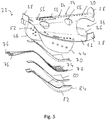
- den Mischer in perspektivischer Ansicht mit in Explosionsdarstellung gezeigter Heizanordnung.
- In
Fig. 1 ist ein Abschnitt einer allgemein mit 10 bezeichneten Abgasanlage einer Brennkraftmaschine eines Fahrzeugs dargestellt. Die Abgasanlage 10 umfasst in einem Abgasrohr 12 einen Abgaskanal 14, in welchen das von einer Brennkraftmaschine, insbesondere einer Dieselbrennkraftmaschine, ausgestoßene Abgas A einströmt. Im Abgaskanal 14 ist ein allgemein mit 16 bezeichneter Mischer angeordnet. Dieser bedeckt im Wesentlichen den gesamten Strömungsquerschnitt des Abgaskanals 14, so dass im Wesentlichen auch das gesamte im Abgaskanal 14 strömende Abgas A durch den nachfolgend detailliert beschriebenen, im Wesentlichen scheibenartig ausgebildeten Mischer 16 hindurchströmen muss. Am Außenumfangsbereich des Mischers 16 können in schlitzartigen Zwischenräumen zwischen diesem und dem Abgasrohr 12 noch Durchströmräume vorhanden sein, in welchen ein geringer Teil des Abgases A, ohne den Mischer 16 zu durchströmen, weiterströmen kann. - Dem Mischer 16 ist eine allgemein als Injektor bezeichnete Reaktionsmittelabgabeanordnung 18 zugeordnet. Durch die Reaktionsmittelabgabeanordnung 18 kann ein Reaktionsmittel, beispielsweise eine Harnstoff/Wasser-Lösung, im Bereich des Mischers 16 in den Abgasstrom eingeleitet und mit dem Abgas A durchmischt werden. Das im Bereich des Mischers 16 somit gebildete Gemisch aus Abgas und Reaktionsmittel strömt im Abgaskanal 14 weiter zu einer Abgasbehandlungseinheit 20, welche eine SCR-Katalysatoranordnung, ggf. auch einen Partikelfilter, umfassen kann. In der SCR-Katalysatoranordnung wird zur Verringerung des Stickoxidanteils im Abgas A das im Bereich des Mischers 16 in das Abgas eingeleitete Reaktionsmittel bei einer selektiven katalytischen Reduktion umgesetzt.
- Nachfolgend wird der Aufbau des Mischers 16 mit Bezug auf die
Fig. 2 bis 5 detailliert beschrieben. - Der Mischer 16 ist mit seiner im Wesentlichen scheibenartigen Gestalt mit an die Innenquerschnittsgeometrie des Abgasrohrs 12 angepasster, näherungsweise kreisrunder Außenquerschnittsgeometrie ausgebildet. Der Mischer 16 umfasst einen Mischerkörper 22 mit zwei beispielsweise als Blechumformteile bereitgestellten Mischerkörperteilen 24, 26. Das im Abgasstrom in Richtung stromaufwärts orientiert zu positionierende erste Mischerkörperteil 24 kann an seinem Außenumfangsbereich mehrere Befestigungslaschen 28 aufweisen, in deren Bereich der Mischerkörper 22 an der Innenseite des Abgasrohrs 12 festgelegt werden kann. Das erste Mischerkörperteil 24 weist in einem zentralen Bereich desselben einen ersten Auswölbungsbereich 30 auf. In Zuordnung zu dem ersten Auswölbungsbereich 30 weist auch das zweite Mischerkörperteil 26 einen zweiten Auswölbungsbereich 32 auf. Diese liegen im Wesentlichen deckungsgleich und definieren einen im Mischerkörper 22 im Wesentlichen radial, radial bezogen auf dessen kreisscheibenartige Gestalt, sich erstreckenden Reaktionsmittelaufnahmekanal 34. An einem Außenumfangsbereich ist der Reaktionsmittelaufnahmekanal 34 offen. In diesem Bereich kann die Reaktionsmittelabgabeanordnung 18 zumindest bereichsweise in den Reaktionsmittelaufnahmekanal 34 eingreifend positioniert sein, so dass das von diesr abgegebene Reaktionsmittel näherungsweise von radial außen nach radial innen in den Reaktionsmittelaufnahmekanal 34 eingeleitet wird. Dabei strömt das Reaktionsmittel ausgehend von einem Reaktionsmittelaufnahmeendbereich 36, in welchen die Reaktionsmittelabgabeanordnung 18 eingreifen kann, zu einem Abgabeendbereich 38 des Reaktionsmittelaufnahmekanals 34. In diesem Abgabeendbereich 38 geht der Reaktionsmittelaufnahmekanal 34 in zwei Abgabekanäle 40, 42 über. Diese sind im Wesentlichen bereitgestellt zwischen dritten Auswölbungsbereichen 44, 46 am zweiten Mischerkörperteil 26 und diesen gegenüberliegenden Bereichen des ersten Mischerkörperteils 24. Die beiden Abgabekanäle 40, 42 führen im Wesentlichen in entgegengesetzten Richtungen im Abgabeendbereich 38 vom Reaktionsmittelaufnahmekanal 34 weg und sind an ihren vom Abgabeendbereich 38 entfernten Ende über jeweilige Abgabekanalöffnungen 48, 50 offen. Um dabei eine effiziente und vor allem auch gleichmäßige Einleitung von Abgas und Reaktionsmittel in die Abgabekanäle 40, 42 zu erreichen, ist am zweiten Mischerkörperteil 26 zwischen den beiden dritten Auswölbungsbereichen 44, 46 eine jeweilige Ablenkflächen bereitstellende Einwölbung 52 gebildet.
- Um den Eintritt von im Abgaskanal 14 strömendem Abgas A in den Mischerkörper 22, insbesondere den Reaktionsmittelaufnahmekanal 34, zu ermöglichen, ist im ersten Mischerkörperteil 30 eine Abgaseintrittsöffnungsanordnung 54 mit einer Vielzahl verschieden gestalteter und verschieden dimensionierter Abgaseintrittsöffnungen 56 vorgesehen. Diese können teilweise so angeordnet sein, dass das durch diese in den Mischerkörper 22 eintretende Abgas in den Reaktionsmittelaufnahmekanal 34 gelangt, können teilweise aber auch so angeordnet sein, dass das durch dieses eintretende Abgas in die Abgabekanäle 40, 42 einströmt. Ferner kann insbesondere am zweiten Mischerkörperteil 26 eine Austrittsöffnungsanordnung 58 mit einer Vielzahl von Austrittsöffnungen 60 vorgesehen sein. Über die Austrittsöffnungen 60 kann zusätzlich zu dem im Bereich der Abgabekanalöffnungen 48, 50 ermöglichten Austritt von Abgas bzw. Reaktionsmittel auch im Bereich der Abgabekanäle 40, 42 Abgas und mit diesem auch Reaktionsmittel aus den Abgabekanälen 40, 42 austreten.
- Die beiden Mischerkörperteile 24, 26 sind miteinander vorzugsweise materialschlüssig, beispielsweise durch Verschweißung, fest verbunden. Dazu können am ersten Mischerkörperteil 24 beidseits des ersten Auswölbungsbereichs 30 Plattenbereiche 62, 64 vorgesehen sein, in deren Bereich das zweite Mischerkörperteil 26 in an den zweiten Auswölbungsbereich 32 bzw. die beiden dritten Auswölbungsbereichen 44, 46 angrenzenden Verbindungsbereichen 66 an das erste Mischerkörperteil 24 angebunden sein kann.
- Der Mischer 16 weist ferner eine allgemein mit 68 bezeichnete Heizanordnung auf. Die Heizanordnung 68 ist am Mischerkörper 22 im Wesentlichen im Bereich des zweiten Mischerkörperteils 26 an der im Abgasrohr 12 in Richtung stromabwärts bezüglich des Abgasstroms orientiert anzuordnenden Außenseite des Mischerkörpers 22 vorgesehen. Die Heizanordnung 68 weist einen geschichteten Aufbau auf. Eine aus thermisch beständigem Material, z.B. als Glimmermatte aufgebaute erste Isolierlage 70 ist anliegend an den Mischerkörper 22, insbesondere das zweite Mischerkörperteil 26, angeordnet. Man erkennt insbesondere in
Fig. 5 , dass die erste Isolierlage 70 eine an die Außenkontur des zweiten Mischerkörperteils 26 insbesondere im Bereich des Einwölbungsbereichs 52 bzw. des zweiten Auswölbungsbereichs 32 angepasste Formgebung aufweist. - An der vom Mischerkörper 22 bzw. vom zweiten Mischerkörperteil 26 abgewandten Seite der ersten Isolierlage 70 ist eine allgemein mit 72 bezeichnete Heizlage angeordnet. Diese umfasst einen vorzugsweise mäanderartig gewundenen Heizleiter 74 mit zwei zur elektrischen Kontaktierung hervorstehenden Anschlussbereichen 76, 78. Zur elektrischen Kontaktierung der Heizanordnung 68 können die beiden Anschlussbereiche 76, 78 beispielsweise durch eine im Abgasrohr 12 im Bereich des Mischers 16 vorgesehene Öffnung hindurchgeführt werden. Diese Öffnung kann in einem Längenbereich des Abgasrohrs 12 vorgesehen sein, in welchem an einer diametral gegenüberliegenden Seite auch eine Öffnung für die Einführung der Reaktionsmittelabgabeanordnung 18 in den Abgaskanal 14 bzw. den Reaktionsmittelaufnahmekanal 34 des Mischers 16 vorgesehen ist.
- An der vom Mischerkörper 22 bzw. auf der ersten Isolierlage 70 abgewandten Seite der Heizlage 72 bzw. des durch elektrische Erregung erwärmbaren Heizleiters 74 ist eine zweite Isolierlage 80 aus thermisch beständigem Material, z.B. als Glimmermatte ausgebildet, angeordnet. Auch diese ist, ebenso wie die Heizlage 72 und die erste Isolierlage 70, an die Formgebung des zweiten Mischerkörperteils 26 angepasst und überdeckt die Heizlage 72 in ihrem an der ersten Isolierlage 70 anliegenden Bereich vollständig.
- Zur Festlegung der Heizanordnung 68 am Mischerkörper 22 ist ein allgemein mit 82 bezeichnetes Abdeckelement vorgesehen. Dieses beispielsweise ebenfalls als Blechumformteil aufgebaute Abdeckelement 82 weist eine auch der Formgebung der beiden Isolierlagen 70, 80 bzw. der Heizlage 72 entsprechende Formgebung auf und weist ferner einen Umfangsrand 84 auf, der zumindest in einigen Bereichen an dem zweiten Mischerkörperteil 26 anliegend an dieses angebunden sein kann, vorzugsweise materialschlüssig. Auch hier kann beispielsweise ein Schweißvorgang verwendet werden, um das Abdeckelement 82 am Mischerkörper 22 festzulegen, so dass die beiden Isolierlagen 70, 80 und die dazwischen angeordnete Heizlage 72 zwischen dem zweiten Mischerkörperteil 26 und dem Abdeckelement 82 festgehalten sind. Obgleich beispielsweise die beiden Isolierlagen 70, 80 mit der Heizlage 72 beispielsweise durch Verklebung oder dergleichen zu einer Baueinheit zusammengefasst sein können, kann dieser Zusammenhalt auch durch das die beiden Isolierlagen 70, 80 und die Heizlage 72 am Mischerkörper 22 festlegende Abdeckelement gewährleistet werden.
- Bei Integration des Mischers 16 in das Abgasrohr 12 wird dieser so angeordnet, dass das zweite Mischerkörperteil 26 und somit auch die Heizanordnung 68 in Richtung stromabwärts bezüglich des Abgasstroms orientiert sind. Auf diese Art und Weise kann gewährleistet werden, dass die durch Erregung der Heizlage 72 bereitgestellte Wärme effizient in den Mischerkörper 22 eingeleitet werden kann. Da die Heizanordnung 68 so angeordnet ist, dass der Heizbereich 72 im Wesentlichen auch den Abgabeendbereich 38 des Reaktionsmittelaufnahmekanals 34 überdeckend angeordnet ist, wird der Mischerkörper 22 insbesondere dort durch die Heizanordnung 68 erwärmt, wo das aus der Reaktionsmittelabgabeanordnung 18 in Spray- bzw. Tröpfchenform abgegebene Reaktionsmittel primär auf die Innenoberfläche des Mischerkörpers 22 auftreffen wird. Somit kann das Reaktionsmittel effizient Wärme aufnehmen und dadurch verdampft werden. Dies gewährleistet bereits im Inneren des Mischers 16 eine effiziente Durchmischung von verdampftem Reaktionsmittel und den Mischer durchströmendem Abgas A.
Claims (16)
- Mischer zur Durchmischung von in einem Abgasführungskanal (14) einer Brennkraftmaschine strömendem Abgas (A) mit in den Abgasführungskanal (14) eingespritztem Reaktionsmittel, umfassend einen Mischerkörper (22) mit- einem Reaktionsmittelaufnahmekanal (34),- einer Abgaseintrittsöffnungsanordnung (54) mit einer Mehrzahl von zu dem Reaktionsmittelaufnahmekanal (34) führenden Abgaseintrittsöffnungen (56),- wenigstens einem von dem Reaktionsmittelaufnahmekanal (34) wegführenden Abgabekanal (40, 42) mit einer Abgabekanalöffnung (48, 50) zur Abgabe eines Reaktionsmittel/Abgas-Gemisches aus dem Mischerkörper (22),dadurch gekennzeichnet, dass an dem Mischerkörper (22) eine elektrisch erregbare Heizanordnung (68) vorgesehen ist.
- Mischer nach Anspruch 1, dadurch gekennzeichnet, dass die Heizanordnung (68) an einer Außenseite des Mischerkörpers (22) angeordnet ist.
- Mischer nach Anspruch 1 oder 2 dadurch gekennzeichnet, dass die Heizanordnung (68) einen geschichteten Aufbau umfasst mit einer dem Mischerkörper (22) zugewandt oder/und an diesem anliegend angeordneten ersten Isolierlage (70), einer an der von dem Mischerkörper (22) abgewandten Seite der ersten Isolierlage (70) angeordneten, durch elektrische Erregung erwärmbaren Heizlage (72) und einer an einer vom Mischerkörper (22) abgewandten Seite der Heizlage (72) angeordneten zweiten Isolierlage (80).
- Mischer nach Anspruch 3, dadurch gekennzeichnet, dass an einer von der Heizlage (72) abgewandten Seite der zweiten Isolierlage (80) ein an dem Mischerkörper (22) festgelegtes Abdeckelement (82) vorgesehen ist, wobei die erste Isolierlage (70), die Heizlage (72) und die zweite Isolierlage (80) zwischen dem Mischerkörper (22) und dem Abdeckelement (82) gehalten sind.
- Mischer nach Anspruch 3 oder 4, dadurch gekennzeichnet, dass die Heizlage (72) einen gewunden verlaufenden Heizleiter (74) umfasst.
- Mischer nach einem der Ansprüche 3 bis 5, dadurch gekennzeichnet, dass wenigstens eine Isolierlage (70, 80) mit Glimmermaterial aufgebaut ist, oder/und das das Abdeckelement (82) mit Metallmaterial aufgebaut ist.
- Mischer nach Anspruch 6, dadurch gekennzeichnet, dass der Mischerkörper (22) mit Metallmaterial aufgebaut ist, und dass das Abdeckelement (82) materialschlüssig, vorzugsweise durch Verschweißen, am Mischerkörper (22) festgelegt ist.
- Mischer nach einem der vorangehenden Ansprüche, dadurch gekennzeichnet, dass der Reaktionsmittelaufnahmekanal (34) einen Reaktionsmittelaufnahmeendbereich (36) und einen Abgabeendbereich (38) aufweist, wobei der wenigstens eine Abgabekanal (40, 42) von dem Reaktionsmittelaufnahmekanal (34) im Abgabeendbereich (38) wegführt, und dass die Heizanordnung (68) wenigstens im Bereich des Abgabeendbereichs (38) des Reaktionsmittelaufnahmekanals (34) am Mischerkörper (22) angeordnet ist.
- Mischer nach einem der vorangehenden Ansprüche, dadurch gekennzeichnet, dass von dem Reaktionsmittelaufnahmekanal (34) zwei Abgabekanäle (40, 42) vorzugsweise in im Wesentlichen entgegengesetzten Richtungen wegführen, und dass die Heizanordnung (68) in einem Bereich zwischen den beiden Abgabekanälen (40, 42) am Mischerkörper (22) angeordnet ist.
- Mischer nach einem vorangehenden Ansprüche, dadurch gekennzeichnet, dass der Mischerkörper (22) ein im Wesentlichen plattenartiges erstes Mischerkörperteil (24) und ein mit dem ersten Mischerkörperteil (24) verbundenes, im Wesentlichen plattenartiges zweites Mischerkörperteil (26) umfasst.
- Mischer nach Anspruch 10, dadurch gekennzeichnet, dass das erste Mischerkörperteil (24) einen den Reaktionsmittelaufnahmekanal (34) begrenzenden ersten Auswölbungsbereich (30) und beidseits des ersten Auswölbungsbereichs (30) einen mit dem zweiten Mischerkörperteil (26) verbundenen oder/und einen Abgabekanal (40, 42) begrenzenden Plattenbereich (62, 64) umfasst, oder/und dass das zweite Mischerkörperteil (26) einen den Reaktionsmittelaufnahmekanal (34) begrenzenden zweiten Auswölbungsbereich (32) und einen den wenigstens einen Abgabekanal (40, 42) begrenzenden dritten Auswölbungsbereich (44, 46) umfasst.
- Mischer nach Anspruch 11, dadurch gekennzeichnet, dass die Heizanordnung (68) am zweiten Mischerkörperteil (26) angeordnet ist.
- Mischer nach einem vorangehenden Ansprüche, dadurch gekennzeichnet, dass eine Austrittsöffnungsanordnung (58) mit einer Mehrzahl von aus dem Reaktionsmittelaufnahmekanal (34) oder/und dem wenigstens einen Abgabekanal (40, 42) herausführenden Austrittsöffnungen (60) vorgesehen ist.
- Abgasanlage für eine Brennkraftmaschine, umfassend einen Abgasführungskanal (14), einen Mischer (16) nach einem der vorangehenden Ansprüche und eine Reaktionsmitteleinspritzanordnung (18) zum Einspritzen von Reaktionsmittel in den Reaktionsmittelaufnahmekanal (34) des Mischers (16).
- Abgasanlage nach Anspruch 14, dadurch gekennzeichnet, dass die Heizanordnung (68) an einer bezüglich einer Abgasströmungsrichtung in Richtung stromabwärts orientierten Seite des Mischerkörpers (22) angeordnet ist.
- Abgasanlage nach Anspruch 14 oder 15, dadurch gekennzeichnet, dass der Mischer (16) in dem Abgasführungskanal (14) im Wesentlichen die gesamte Strömungsquerschnittfläche des Abgasführungskanals (14) bedeckt, oder/und dass der Reaktionsmittelaufnahmekanal (34) oder/und der wenigstens eine Abgabekanal (40, 42) sich im Wesentlichen orthogonal zu einer Abgasströmungsrichtung im Abgasführungskanal (14) erstreckt, oder/und dass die Reaktionsmitteleinspritzanordnung (18) Reaktionsmittel im Wesentlichen orthogonal zu der Abgasströmungsrichtung im Abgasführungskanal (14) einspritzt, oder/und dass stromabwärts des Mischers (16) eine Katalysatoranordnung zur selektiven Reduktion oder/und eine Partikelfilteranordnung vorgesehen ist.
Applications Claiming Priority (1)
| Application Number | Priority Date | Filing Date | Title |
|---|---|---|---|
| DE102018114755.4A DE102018114755A1 (de) | 2018-06-20 | 2018-06-20 | Mischer |
Publications (2)
| Publication Number | Publication Date |
|---|---|
| EP3584003A1 true EP3584003A1 (de) | 2019-12-25 |
| EP3584003B1 EP3584003B1 (de) | 2021-09-29 |
Family
ID=66857740
Family Applications (1)
| Application Number | Title | Priority Date | Filing Date |
|---|---|---|---|
| EP19179913.9A Active EP3584003B1 (de) | 2018-06-20 | 2019-06-13 | Mischer |
Country Status (4)
| Country | Link |
|---|---|
| US (1) | US11278850B2 (de) |
| EP (1) | EP3584003B1 (de) |
| CN (1) | CN110617132B (de) |
| DE (1) | DE102018114755A1 (de) |
Families Citing this family (8)
| Publication number | Priority date | Publication date | Assignee | Title |
|---|---|---|---|---|
| DE102019109983A1 (de) | 2019-04-16 | 2020-10-22 | Eberspächer Exhaust Technology GmbH & Co. KG | Mischer |
| JP7345405B2 (ja) * | 2019-05-30 | 2023-09-15 | 日本碍子株式会社 | 排ガス浄化装置用混合器、排ガス浄化装置及び排ガス浄化方法 |
| US10767537B1 (en) * | 2019-06-28 | 2020-09-08 | GM Global Technology Operations LLC | Hydrocarbon injector deflector assembly for diesel exhaust system |
| US10961887B2 (en) * | 2019-07-03 | 2021-03-30 | Deere & Company | Integrated reductant mixer and heater apparatus for exhaust treatment systems |
| US11585255B2 (en) | 2020-11-23 | 2023-02-21 | Faurecia Emissions Control Technologies, Usa, Llc | Crowned inlet baffle for high efficiency mixer |
| DE102022205337A1 (de) | 2022-05-30 | 2023-11-30 | Robert Bosch Gesellschaft mit beschränkter Haftung | Mischeranordnung für eine Abgasanlage, Abgasanlage |
| DE202022103093U1 (de) | 2022-05-30 | 2022-06-21 | Robert Bosch Gesellschaft mit beschränkter Haftung | Mischeranordnung für eine Abgasanlage, Abgasanlage |
| JP2025171357A (ja) * | 2024-05-09 | 2025-11-20 | いすゞ自動車株式会社 | 排気処理装置 |
Citations (5)
| Publication number | Priority date | Publication date | Assignee | Title |
|---|---|---|---|---|
| US20050013756A1 (en) * | 2003-05-28 | 2005-01-20 | Kiyoshi Amou | Engine exhaust gas treatment system and exhaust gas treatment process |
| US20170159526A1 (en) * | 2014-06-25 | 2017-06-08 | Baumot Ag | Apparatus and method for producing ammonia for exhaust gas aftertreatment |
| DE102016104361A1 (de) | 2016-03-10 | 2017-09-14 | Eberspächer Exhaust Technology GmbH & Co. KG | Mischer |
| US20180080360A1 (en) * | 2016-09-21 | 2018-03-22 | Eberspächer Exhaust Technology GmbH & Co. KG | Reactant introduction device for introducing reactant into the exhaust gas stream of an internal combustion engine |
| EP3321484A1 (de) * | 2016-11-14 | 2018-05-16 | Eberspächer Exhaust Technology GmbH & Co. KG | Reaktionsmittelabgabeanordnung |
Family Cites Families (15)
| Publication number | Priority date | Publication date | Assignee | Title |
|---|---|---|---|---|
| JPH03206314A (ja) | 1990-01-08 | 1991-09-09 | Yanmar Diesel Engine Co Ltd | ディーゼルエンジンのアンモニア脱硝システムにおける還元剤水溶液注入ノズル装置 |
| ATE250969T1 (de) * | 1997-07-28 | 2003-10-15 | Siemens Ag | Verwendung eines statischer mischers als hydrilysekatalysator sowie dessen verwendung in einer abgasleitung für eine verbrennungsanlage |
| JP4706757B2 (ja) | 2009-01-15 | 2011-06-22 | トヨタ自動車株式会社 | 内燃機関の排気浄化装置 |
| DE202012011764U1 (de) * | 2012-12-07 | 2013-03-21 | Eberspächer Catem Gmbh & Co. Kg | Mischer zur Nachbehandlung von Abgasen |
| EP2826973B1 (de) * | 2013-07-18 | 2017-10-25 | FPT Motorenforschung AG | System zur Verhinderung der Harnstoffkristallbildung in einem Abgasnachbehandlungssystem |
| FR3014136B1 (fr) | 2013-12-03 | 2018-04-20 | Faurecia Systemes D'echappement | Dispositif d'injection d'un reducteur et ligne d'echappement correspondante |
| DE102014205156A1 (de) * | 2014-03-19 | 2015-09-24 | Eberspächer Exhaust Technology GmbH & Co. KG | Abgasanlage |
| DE102014111310B4 (de) * | 2014-08-07 | 2021-05-06 | Denso Corporation | Abgasmischer mit integrierter Heizeinrichtung |
| US9828897B2 (en) * | 2015-04-30 | 2017-11-28 | Faurecia Emissions Control Technologies Usa, Llc | Mixer for a vehicle exhaust system |
| DE102016107213A1 (de) * | 2016-03-03 | 2017-09-07 | Eberspächer Exhaust Technology GmbH & Co. KG | Abgasanlage, insbesondere für eine Brennkraftmaschine eines Fahrzeugs |
| DE102017100246A1 (de) | 2016-11-14 | 2018-05-17 | Eberspächer Exhaust Technology GmbH & Co. KG | Reaktionsmittelabgabeanordnung |
| US10329985B2 (en) * | 2017-06-27 | 2019-06-25 | Tenneco Automotive Operating Company Inc. | Impingement mixer for exhaust treatment |
| US10577995B2 (en) * | 2017-08-25 | 2020-03-03 | Faurecia Emissions Control Technologies, Usa, Llc | Double wall mixer with active heat transfer |
| EP3492718B1 (de) * | 2017-11-30 | 2020-06-10 | Katcon Global S.A. | Abgasleitung für ein fahrzeug |
| US10787946B2 (en) * | 2018-09-19 | 2020-09-29 | Faurecia Emissions Control Technologies, Usa, Llc | Heated dosing mixer |
-
2018
- 2018-06-20 DE DE102018114755.4A patent/DE102018114755A1/de not_active Withdrawn
-
2019
- 2019-06-13 EP EP19179913.9A patent/EP3584003B1/de active Active
- 2019-06-18 US US16/444,908 patent/US11278850B2/en active Active
- 2019-06-19 CN CN201910528920.3A patent/CN110617132B/zh active Active
Patent Citations (5)
| Publication number | Priority date | Publication date | Assignee | Title |
|---|---|---|---|---|
| US20050013756A1 (en) * | 2003-05-28 | 2005-01-20 | Kiyoshi Amou | Engine exhaust gas treatment system and exhaust gas treatment process |
| US20170159526A1 (en) * | 2014-06-25 | 2017-06-08 | Baumot Ag | Apparatus and method for producing ammonia for exhaust gas aftertreatment |
| DE102016104361A1 (de) | 2016-03-10 | 2017-09-14 | Eberspächer Exhaust Technology GmbH & Co. KG | Mischer |
| US20180080360A1 (en) * | 2016-09-21 | 2018-03-22 | Eberspächer Exhaust Technology GmbH & Co. KG | Reactant introduction device for introducing reactant into the exhaust gas stream of an internal combustion engine |
| EP3321484A1 (de) * | 2016-11-14 | 2018-05-16 | Eberspächer Exhaust Technology GmbH & Co. KG | Reaktionsmittelabgabeanordnung |
Also Published As
| Publication number | Publication date |
|---|---|
| CN110617132A (zh) | 2019-12-27 |
| EP3584003B1 (de) | 2021-09-29 |
| DE102018114755A1 (de) | 2019-12-24 |
| US20190388848A1 (en) | 2019-12-26 |
| CN110617132B (zh) | 2021-09-14 |
| US11278850B2 (en) | 2022-03-22 |
Similar Documents
| Publication | Publication Date | Title |
|---|---|---|
| EP3584003B1 (de) | Mischer | |
| DE102015115220B4 (de) | Mischerbaugruppe zur Bereitstellung eines kompakten Mischers | |
| EP3299598B1 (de) | Reaktionsmitteleingabeanordnung zur eingabe von reaktionsmittel in den abgasstrom einer brennkraftmaschine | |
| EP3216992B1 (de) | Mischer | |
| DE112012006960B4 (de) | Abgasanlage-Mischeinrichtung mit Impaktor | |
| EP3473827B1 (de) | Mischanordnung | |
| DE112017003665T5 (de) | Strömungsumlenker zur minderung von ablagerungen in einem dosiererkegel | |
| DE102006058402A1 (de) | Vorrichtung zum Zumischen eines Reduktionsmittels in einen Abgasstrom einer Brennkraftmaschine | |
| DE112017007089T5 (de) | Abgasnachbehandlungseinrichtung | |
| DE102019117459A1 (de) | Mischer | |
| EP3808949B1 (de) | Mischeranordnung | |
| EP3611354B1 (de) | Mischer | |
| DE102020124104A1 (de) | Zersetzungsrohr für aufgeheizten dosierer | |
| DE102017101749A1 (de) | Mischerelement zum Einmischen eines Fluids in ein Abgas eines Verbrennungsmotors sowie Abgasstrang für einen Verbrennungsmotor | |
| EP4382730B1 (de) | Abgasbehandlungsanordnung | |
| EP3321484B1 (de) | Reaktionsmittelabgabeanordnung | |
| EP3851646B1 (de) | Gas/gas-mischer zum einleiten von gas in den abgasstrom einer brennkraftmaschine | |
| DE102012014528A1 (de) | Mehrstufiger Plattenmischer | |
| DE102019104772A1 (de) | Abgasanlage | |
| EP4390069B1 (de) | Abgasbehandlungsanordnung | |
| EP3470641B1 (de) | Abgasanlage | |
| EP4080025B1 (de) | Abgas/reaktionsmittel-mischanordnung | |
| EP3611355B1 (de) | Abgasbehandlungsanordnung | |
| DE102022132126A1 (de) | Abgasbehandlungsanordnung | |
| DE102022132125A1 (de) | Abgasbehandlungsanordnung |
Legal Events
| Date | Code | Title | Description |
|---|---|---|---|
| PUAI | Public reference made under article 153(3) epc to a published international application that has entered the european phase |
Free format text: ORIGINAL CODE: 0009012 |
|
| STAA | Information on the status of an ep patent application or granted ep patent |
Free format text: STATUS: THE APPLICATION HAS BEEN PUBLISHED |
|
| AK | Designated contracting states |
Kind code of ref document: A1 Designated state(s): AL AT BE BG CH CY CZ DE DK EE ES FI FR GB GR HR HU IE IS IT LI LT LU LV MC MK MT NL NO PL PT RO RS SE SI SK SM TR |
|
| AX | Request for extension of the european patent |
Extension state: BA ME |
|
| STAA | Information on the status of an ep patent application or granted ep patent |
Free format text: STATUS: REQUEST FOR EXAMINATION WAS MADE |
|
| 17P | Request for examination filed |
Effective date: 20200408 |
|
| RBV | Designated contracting states (corrected) |
Designated state(s): AL AT BE BG CH CY CZ DE DK EE ES FI FR GB GR HR HU IE IS IT LI LT LU LV MC MK MT NL NO PL PT RO RS SE SI SK SM TR |
|
| GRAP | Despatch of communication of intention to grant a patent |
Free format text: ORIGINAL CODE: EPIDOSNIGR1 |
|
| STAA | Information on the status of an ep patent application or granted ep patent |
Free format text: STATUS: GRANT OF PATENT IS INTENDED |
|
| INTG | Intention to grant announced |
Effective date: 20210721 |
|
| GRAS | Grant fee paid |
Free format text: ORIGINAL CODE: EPIDOSNIGR3 |
|
| RAP1 | Party data changed (applicant data changed or rights of an application transferred) |
Owner name: PUREM GMBH |
|
| GRAA | (expected) grant |
Free format text: ORIGINAL CODE: 0009210 |
|
| STAA | Information on the status of an ep patent application or granted ep patent |
Free format text: STATUS: THE PATENT HAS BEEN GRANTED |
|
| AK | Designated contracting states |
Kind code of ref document: B1 Designated state(s): AL AT BE BG CH CY CZ DE DK EE ES FI FR GB GR HR HU IE IS IT LI LT LU LV MC MK MT NL NO PL PT RO RS SE SI SK SM TR |
|
| REG | Reference to a national code |
Ref country code: GB Ref legal event code: FG4D Free format text: NOT ENGLISH |
|
| REG | Reference to a national code |
Ref country code: CH Ref legal event code: EP Ref country code: AT Ref legal event code: REF Ref document number: 1433712 Country of ref document: AT Kind code of ref document: T Effective date: 20211015 |
|
| REG | Reference to a national code |
Ref country code: DE Ref legal event code: R096 Ref document number: 502019002372 Country of ref document: DE |
|
| REG | Reference to a national code |
Ref country code: IE Ref legal event code: FG4D Free format text: LANGUAGE OF EP DOCUMENT: GERMAN |
|
| REG | Reference to a national code |
Ref country code: DE Ref legal event code: R079 Ref document number: 502019002372 Country of ref document: DE Free format text: PREVIOUS MAIN CLASS: B01F0003040000 Ipc: B01F0023200000 |
|
| REG | Reference to a national code |
Ref country code: LT Ref legal event code: MG9D |
|
| PG25 | Lapsed in a contracting state [announced via postgrant information from national office to epo] |
Ref country code: HR Free format text: LAPSE BECAUSE OF FAILURE TO SUBMIT A TRANSLATION OF THE DESCRIPTION OR TO PAY THE FEE WITHIN THE PRESCRIBED TIME-LIMIT Effective date: 20210929 Ref country code: NO Free format text: LAPSE BECAUSE OF FAILURE TO SUBMIT A TRANSLATION OF THE DESCRIPTION OR TO PAY THE FEE WITHIN THE PRESCRIBED TIME-LIMIT Effective date: 20211229 Ref country code: LT Free format text: LAPSE BECAUSE OF FAILURE TO SUBMIT A TRANSLATION OF THE DESCRIPTION OR TO PAY THE FEE WITHIN THE PRESCRIBED TIME-LIMIT Effective date: 20210929 Ref country code: BG Free format text: LAPSE BECAUSE OF FAILURE TO SUBMIT A TRANSLATION OF THE DESCRIPTION OR TO PAY THE FEE WITHIN THE PRESCRIBED TIME-LIMIT Effective date: 20211229 Ref country code: FI Free format text: LAPSE BECAUSE OF FAILURE TO SUBMIT A TRANSLATION OF THE DESCRIPTION OR TO PAY THE FEE WITHIN THE PRESCRIBED TIME-LIMIT Effective date: 20210929 Ref country code: SE Free format text: LAPSE BECAUSE OF FAILURE TO SUBMIT A TRANSLATION OF THE DESCRIPTION OR TO PAY THE FEE WITHIN THE PRESCRIBED TIME-LIMIT Effective date: 20210929 Ref country code: RS Free format text: LAPSE BECAUSE OF FAILURE TO SUBMIT A TRANSLATION OF THE DESCRIPTION OR TO PAY THE FEE WITHIN THE PRESCRIBED TIME-LIMIT Effective date: 20210929 |
|
| REG | Reference to a national code |
Ref country code: NL Ref legal event code: MP Effective date: 20210929 |
|
| PG25 | Lapsed in a contracting state [announced via postgrant information from national office to epo] |
Ref country code: LV Free format text: LAPSE BECAUSE OF FAILURE TO SUBMIT A TRANSLATION OF THE DESCRIPTION OR TO PAY THE FEE WITHIN THE PRESCRIBED TIME-LIMIT Effective date: 20210929 Ref country code: GR Free format text: LAPSE BECAUSE OF FAILURE TO SUBMIT A TRANSLATION OF THE DESCRIPTION OR TO PAY THE FEE WITHIN THE PRESCRIBED TIME-LIMIT Effective date: 20211230 |
|
| PG25 | Lapsed in a contracting state [announced via postgrant information from national office to epo] |
Ref country code: IS Free format text: LAPSE BECAUSE OF FAILURE TO SUBMIT A TRANSLATION OF THE DESCRIPTION OR TO PAY THE FEE WITHIN THE PRESCRIBED TIME-LIMIT Effective date: 20220129 Ref country code: SK Free format text: LAPSE BECAUSE OF FAILURE TO SUBMIT A TRANSLATION OF THE DESCRIPTION OR TO PAY THE FEE WITHIN THE PRESCRIBED TIME-LIMIT Effective date: 20210929 Ref country code: RO Free format text: LAPSE BECAUSE OF FAILURE TO SUBMIT A TRANSLATION OF THE DESCRIPTION OR TO PAY THE FEE WITHIN THE PRESCRIBED TIME-LIMIT Effective date: 20210929 Ref country code: PT Free format text: LAPSE BECAUSE OF FAILURE TO SUBMIT A TRANSLATION OF THE DESCRIPTION OR TO PAY THE FEE WITHIN THE PRESCRIBED TIME-LIMIT Effective date: 20220131 Ref country code: PL Free format text: LAPSE BECAUSE OF FAILURE TO SUBMIT A TRANSLATION OF THE DESCRIPTION OR TO PAY THE FEE WITHIN THE PRESCRIBED TIME-LIMIT Effective date: 20210929 Ref country code: NL Free format text: LAPSE BECAUSE OF FAILURE TO SUBMIT A TRANSLATION OF THE DESCRIPTION OR TO PAY THE FEE WITHIN THE PRESCRIBED TIME-LIMIT Effective date: 20210929 Ref country code: ES Free format text: LAPSE BECAUSE OF FAILURE TO SUBMIT A TRANSLATION OF THE DESCRIPTION OR TO PAY THE FEE WITHIN THE PRESCRIBED TIME-LIMIT Effective date: 20210929 Ref country code: EE Free format text: LAPSE BECAUSE OF FAILURE TO SUBMIT A TRANSLATION OF THE DESCRIPTION OR TO PAY THE FEE WITHIN THE PRESCRIBED TIME-LIMIT Effective date: 20210929 Ref country code: CZ Free format text: LAPSE BECAUSE OF FAILURE TO SUBMIT A TRANSLATION OF THE DESCRIPTION OR TO PAY THE FEE WITHIN THE PRESCRIBED TIME-LIMIT Effective date: 20210929 Ref country code: AL Free format text: LAPSE BECAUSE OF FAILURE TO SUBMIT A TRANSLATION OF THE DESCRIPTION OR TO PAY THE FEE WITHIN THE PRESCRIBED TIME-LIMIT Effective date: 20210929 |
|
| REG | Reference to a national code |
Ref country code: DE Ref legal event code: R097 Ref document number: 502019002372 Country of ref document: DE |
|
| PG25 | Lapsed in a contracting state [announced via postgrant information from national office to epo] |
Ref country code: DK Free format text: LAPSE BECAUSE OF FAILURE TO SUBMIT A TRANSLATION OF THE DESCRIPTION OR TO PAY THE FEE WITHIN THE PRESCRIBED TIME-LIMIT Effective date: 20210929 |
|
| PLBE | No opposition filed within time limit |
Free format text: ORIGINAL CODE: 0009261 |
|
| STAA | Information on the status of an ep patent application or granted ep patent |
Free format text: STATUS: NO OPPOSITION FILED WITHIN TIME LIMIT |
|
| 26N | No opposition filed |
Effective date: 20220630 |
|
| PG25 | Lapsed in a contracting state [announced via postgrant information from national office to epo] |
Ref country code: SI Free format text: LAPSE BECAUSE OF FAILURE TO SUBMIT A TRANSLATION OF THE DESCRIPTION OR TO PAY THE FEE WITHIN THE PRESCRIBED TIME-LIMIT Effective date: 20210929 |
|
| PG25 | Lapsed in a contracting state [announced via postgrant information from national office to epo] |
Ref country code: MC Free format text: LAPSE BECAUSE OF FAILURE TO SUBMIT A TRANSLATION OF THE DESCRIPTION OR TO PAY THE FEE WITHIN THE PRESCRIBED TIME-LIMIT Effective date: 20210929 Ref country code: IT Free format text: LAPSE BECAUSE OF FAILURE TO SUBMIT A TRANSLATION OF THE DESCRIPTION OR TO PAY THE FEE WITHIN THE PRESCRIBED TIME-LIMIT Effective date: 20210929 |
|
| REG | Reference to a national code |
Ref country code: CH Ref legal event code: PL |
|
| REG | Reference to a national code |
Ref country code: BE Ref legal event code: MM Effective date: 20220630 |
|
| PG25 | Lapsed in a contracting state [announced via postgrant information from national office to epo] |
Ref country code: LU Free format text: LAPSE BECAUSE OF NON-PAYMENT OF DUE FEES Effective date: 20220613 Ref country code: LI Free format text: LAPSE BECAUSE OF NON-PAYMENT OF DUE FEES Effective date: 20220630 Ref country code: IE Free format text: LAPSE BECAUSE OF NON-PAYMENT OF DUE FEES Effective date: 20220613 Ref country code: CH Free format text: LAPSE BECAUSE OF NON-PAYMENT OF DUE FEES Effective date: 20220630 |
|
| PG25 | Lapsed in a contracting state [announced via postgrant information from national office to epo] |
Ref country code: BE Free format text: LAPSE BECAUSE OF NON-PAYMENT OF DUE FEES Effective date: 20220630 |
|
| PG25 | Lapsed in a contracting state [announced via postgrant information from national office to epo] |
Ref country code: SM Free format text: LAPSE BECAUSE OF FAILURE TO SUBMIT A TRANSLATION OF THE DESCRIPTION OR TO PAY THE FEE WITHIN THE PRESCRIBED TIME-LIMIT Effective date: 20210929 Ref country code: MK Free format text: LAPSE BECAUSE OF FAILURE TO SUBMIT A TRANSLATION OF THE DESCRIPTION OR TO PAY THE FEE WITHIN THE PRESCRIBED TIME-LIMIT Effective date: 20210929 Ref country code: CY Free format text: LAPSE BECAUSE OF FAILURE TO SUBMIT A TRANSLATION OF THE DESCRIPTION OR TO PAY THE FEE WITHIN THE PRESCRIBED TIME-LIMIT Effective date: 20210929 |
|
| PG25 | Lapsed in a contracting state [announced via postgrant information from national office to epo] |
Ref country code: HU Free format text: LAPSE BECAUSE OF FAILURE TO SUBMIT A TRANSLATION OF THE DESCRIPTION OR TO PAY THE FEE WITHIN THE PRESCRIBED TIME-LIMIT; INVALID AB INITIO Effective date: 20190613 |
|
| PG25 | Lapsed in a contracting state [announced via postgrant information from national office to epo] |
Ref country code: TR Free format text: LAPSE BECAUSE OF FAILURE TO SUBMIT A TRANSLATION OF THE DESCRIPTION OR TO PAY THE FEE WITHIN THE PRESCRIBED TIME-LIMIT Effective date: 20210929 |
|
| PG25 | Lapsed in a contracting state [announced via postgrant information from national office to epo] |
Ref country code: MT Free format text: LAPSE BECAUSE OF FAILURE TO SUBMIT A TRANSLATION OF THE DESCRIPTION OR TO PAY THE FEE WITHIN THE PRESCRIBED TIME-LIMIT Effective date: 20210929 |
|
| PGFP | Annual fee paid to national office [announced via postgrant information from national office to epo] |
Ref country code: DE Payment date: 20250618 Year of fee payment: 7 |
|
| PGFP | Annual fee paid to national office [announced via postgrant information from national office to epo] |
Ref country code: GB Payment date: 20250620 Year of fee payment: 7 |
|
| PGFP | Annual fee paid to national office [announced via postgrant information from national office to epo] |
Ref country code: FR Payment date: 20250618 Year of fee payment: 7 |
|
| REG | Reference to a national code |
Ref country code: AT Ref legal event code: MM01 Ref document number: 1433712 Country of ref document: AT Kind code of ref document: T Effective date: 20240613 |
|
| PG25 | Lapsed in a contracting state [announced via postgrant information from national office to epo] |
Ref country code: AT Free format text: LAPSE BECAUSE OF NON-PAYMENT OF DUE FEES Effective date: 20240613 |
|
| PGFP | Annual fee paid to national office [announced via postgrant information from national office to epo] |
Ref country code: AT Payment date: 20260410 Year of fee payment: 5 |