EP3582886B1 - Verfahren zur maximierung der methanolausbeute unter verwendung von katalysatorschichten - Google Patents
Verfahren zur maximierung der methanolausbeute unter verwendung von katalysatorschichten Download PDFInfo
- Publication number
- EP3582886B1 EP3582886B1 EP18705374.9A EP18705374A EP3582886B1 EP 3582886 B1 EP3582886 B1 EP 3582886B1 EP 18705374 A EP18705374 A EP 18705374A EP 3582886 B1 EP3582886 B1 EP 3582886B1
- Authority
- EP
- European Patent Office
- Prior art keywords
- reactor
- catalyst
- activity
- layer
- catalyst layers
- Prior art date
- Legal status (The legal status is an assumption and is not a legal conclusion. Google has not performed a legal analysis and makes no representation as to the accuracy of the status listed.)
- Active
Links
Images


Classifications
-
- B—PERFORMING OPERATIONS; TRANSPORTING
- B01—PHYSICAL OR CHEMICAL PROCESSES OR APPARATUS IN GENERAL
- B01J—CHEMICAL OR PHYSICAL PROCESSES, e.g. CATALYSIS OR COLLOID CHEMISTRY; THEIR RELEVANT APPARATUS
- B01J8/00—Chemical or physical processes in general, conducted in the presence of fluids and solid particles; Apparatus for such processes
- B01J8/02—Chemical or physical processes in general, conducted in the presence of fluids and solid particles; Apparatus for such processes with stationary particles, e.g. in fixed beds
- B01J8/04—Chemical or physical processes in general, conducted in the presence of fluids and solid particles; Apparatus for such processes with stationary particles, e.g. in fixed beds the fluid passing successively through two or more beds
- B01J8/0492—Feeding reactive fluids
-
- C—CHEMISTRY; METALLURGY
- C07—ORGANIC CHEMISTRY
- C07C—ACYCLIC OR CARBOCYCLIC COMPOUNDS
- C07C29/00—Preparation of compounds having hydroxy or O-metal groups bound to a carbon atom not belonging to a six-membered aromatic ring
- C07C29/15—Preparation of compounds having hydroxy or O-metal groups bound to a carbon atom not belonging to a six-membered aromatic ring by reduction of oxides of carbon exclusively
- C07C29/151—Preparation of compounds having hydroxy or O-metal groups bound to a carbon atom not belonging to a six-membered aromatic ring by reduction of oxides of carbon exclusively with hydrogen or hydrogen-containing gases
- C07C29/153—Preparation of compounds having hydroxy or O-metal groups bound to a carbon atom not belonging to a six-membered aromatic ring by reduction of oxides of carbon exclusively with hydrogen or hydrogen-containing gases characterised by the catalyst used
- C07C29/154—Preparation of compounds having hydroxy or O-metal groups bound to a carbon atom not belonging to a six-membered aromatic ring by reduction of oxides of carbon exclusively with hydrogen or hydrogen-containing gases characterised by the catalyst used containing copper, silver, gold, or compounds thereof
-
- C—CHEMISTRY; METALLURGY
- C07—ORGANIC CHEMISTRY
- C07C—ACYCLIC OR CARBOCYCLIC COMPOUNDS
- C07C29/00—Preparation of compounds having hydroxy or O-metal groups bound to a carbon atom not belonging to a six-membered aromatic ring
- C07C29/15—Preparation of compounds having hydroxy or O-metal groups bound to a carbon atom not belonging to a six-membered aromatic ring by reduction of oxides of carbon exclusively
- C07C29/151—Preparation of compounds having hydroxy or O-metal groups bound to a carbon atom not belonging to a six-membered aromatic ring by reduction of oxides of carbon exclusively with hydrogen or hydrogen-containing gases
- C07C29/153—Preparation of compounds having hydroxy or O-metal groups bound to a carbon atom not belonging to a six-membered aromatic ring by reduction of oxides of carbon exclusively with hydrogen or hydrogen-containing gases characterised by the catalyst used
-
- B—PERFORMING OPERATIONS; TRANSPORTING
- B01—PHYSICAL OR CHEMICAL PROCESSES OR APPARATUS IN GENERAL
- B01J—CHEMICAL OR PHYSICAL PROCESSES, e.g. CATALYSIS OR COLLOID CHEMISTRY; THEIR RELEVANT APPARATUS
- B01J8/00—Chemical or physical processes in general, conducted in the presence of fluids and solid particles; Apparatus for such processes
- B01J8/02—Chemical or physical processes in general, conducted in the presence of fluids and solid particles; Apparatus for such processes with stationary particles, e.g. in fixed beds
- B01J8/04—Chemical or physical processes in general, conducted in the presence of fluids and solid particles; Apparatus for such processes with stationary particles, e.g. in fixed beds the fluid passing successively through two or more beds
-
- B—PERFORMING OPERATIONS; TRANSPORTING
- B01—PHYSICAL OR CHEMICAL PROCESSES OR APPARATUS IN GENERAL
- B01J—CHEMICAL OR PHYSICAL PROCESSES, e.g. CATALYSIS OR COLLOID CHEMISTRY; THEIR RELEVANT APPARATUS
- B01J8/00—Chemical or physical processes in general, conducted in the presence of fluids and solid particles; Apparatus for such processes
- B01J8/02—Chemical or physical processes in general, conducted in the presence of fluids and solid particles; Apparatus for such processes with stationary particles, e.g. in fixed beds
- B01J8/04—Chemical or physical processes in general, conducted in the presence of fluids and solid particles; Apparatus for such processes with stationary particles, e.g. in fixed beds the fluid passing successively through two or more beds
- B01J8/0446—Chemical or physical processes in general, conducted in the presence of fluids and solid particles; Apparatus for such processes with stationary particles, e.g. in fixed beds the fluid passing successively through two or more beds the flow within the beds being predominantly vertical
- B01J8/0449—Chemical or physical processes in general, conducted in the presence of fluids and solid particles; Apparatus for such processes with stationary particles, e.g. in fixed beds the fluid passing successively through two or more beds the flow within the beds being predominantly vertical in two or more cylindrical beds
- B01J8/0453—Chemical or physical processes in general, conducted in the presence of fluids and solid particles; Apparatus for such processes with stationary particles, e.g. in fixed beds the fluid passing successively through two or more beds the flow within the beds being predominantly vertical in two or more cylindrical beds the beds being superimposed one above the other
-
- B—PERFORMING OPERATIONS; TRANSPORTING
- B01—PHYSICAL OR CHEMICAL PROCESSES OR APPARATUS IN GENERAL
- B01J—CHEMICAL OR PHYSICAL PROCESSES, e.g. CATALYSIS OR COLLOID CHEMISTRY; THEIR RELEVANT APPARATUS
- B01J8/00—Chemical or physical processes in general, conducted in the presence of fluids and solid particles; Apparatus for such processes
- B01J8/02—Chemical or physical processes in general, conducted in the presence of fluids and solid particles; Apparatus for such processes with stationary particles, e.g. in fixed beds
- B01J8/04—Chemical or physical processes in general, conducted in the presence of fluids and solid particles; Apparatus for such processes with stationary particles, e.g. in fixed beds the fluid passing successively through two or more beds
- B01J8/0446—Chemical or physical processes in general, conducted in the presence of fluids and solid particles; Apparatus for such processes with stationary particles, e.g. in fixed beds the fluid passing successively through two or more beds the flow within the beds being predominantly vertical
- B01J8/0449—Chemical or physical processes in general, conducted in the presence of fluids and solid particles; Apparatus for such processes with stationary particles, e.g. in fixed beds the fluid passing successively through two or more beds the flow within the beds being predominantly vertical in two or more cylindrical beds
- B01J8/0457—Chemical or physical processes in general, conducted in the presence of fluids and solid particles; Apparatus for such processes with stationary particles, e.g. in fixed beds the fluid passing successively through two or more beds the flow within the beds being predominantly vertical in two or more cylindrical beds the beds being placed in separate reactors
-
- B—PERFORMING OPERATIONS; TRANSPORTING
- B01—PHYSICAL OR CHEMICAL PROCESSES OR APPARATUS IN GENERAL
- B01J—CHEMICAL OR PHYSICAL PROCESSES, e.g. CATALYSIS OR COLLOID CHEMISTRY; THEIR RELEVANT APPARATUS
- B01J8/00—Chemical or physical processes in general, conducted in the presence of fluids and solid particles; Apparatus for such processes
- B01J8/02—Chemical or physical processes in general, conducted in the presence of fluids and solid particles; Apparatus for such processes with stationary particles, e.g. in fixed beds
- B01J8/04—Chemical or physical processes in general, conducted in the presence of fluids and solid particles; Apparatus for such processes with stationary particles, e.g. in fixed beds the fluid passing successively through two or more beds
- B01J8/0496—Heating or cooling the reactor
-
- C—CHEMISTRY; METALLURGY
- C07—ORGANIC CHEMISTRY
- C07C—ACYCLIC OR CARBOCYCLIC COMPOUNDS
- C07C29/00—Preparation of compounds having hydroxy or O-metal groups bound to a carbon atom not belonging to a six-membered aromatic ring
- C07C29/15—Preparation of compounds having hydroxy or O-metal groups bound to a carbon atom not belonging to a six-membered aromatic ring by reduction of oxides of carbon exclusively
- C07C29/151—Preparation of compounds having hydroxy or O-metal groups bound to a carbon atom not belonging to a six-membered aromatic ring by reduction of oxides of carbon exclusively with hydrogen or hydrogen-containing gases
-
- C—CHEMISTRY; METALLURGY
- C07—ORGANIC CHEMISTRY
- C07C—ACYCLIC OR CARBOCYCLIC COMPOUNDS
- C07C29/00—Preparation of compounds having hydroxy or O-metal groups bound to a carbon atom not belonging to a six-membered aromatic ring
- C07C29/15—Preparation of compounds having hydroxy or O-metal groups bound to a carbon atom not belonging to a six-membered aromatic ring by reduction of oxides of carbon exclusively
- C07C29/151—Preparation of compounds having hydroxy or O-metal groups bound to a carbon atom not belonging to a six-membered aromatic ring by reduction of oxides of carbon exclusively with hydrogen or hydrogen-containing gases
- C07C29/1516—Multisteps
-
- C—CHEMISTRY; METALLURGY
- C07—ORGANIC CHEMISTRY
- C07C—ACYCLIC OR CARBOCYCLIC COMPOUNDS
- C07C29/00—Preparation of compounds having hydroxy or O-metal groups bound to a carbon atom not belonging to a six-membered aromatic ring
- C07C29/15—Preparation of compounds having hydroxy or O-metal groups bound to a carbon atom not belonging to a six-membered aromatic ring by reduction of oxides of carbon exclusively
- C07C29/151—Preparation of compounds having hydroxy or O-metal groups bound to a carbon atom not belonging to a six-membered aromatic ring by reduction of oxides of carbon exclusively with hydrogen or hydrogen-containing gases
- C07C29/152—Preparation of compounds having hydroxy or O-metal groups bound to a carbon atom not belonging to a six-membered aromatic ring by reduction of oxides of carbon exclusively with hydrogen or hydrogen-containing gases characterised by the reactor used
-
- B—PERFORMING OPERATIONS; TRANSPORTING
- B01—PHYSICAL OR CHEMICAL PROCESSES OR APPARATUS IN GENERAL
- B01J—CHEMICAL OR PHYSICAL PROCESSES, e.g. CATALYSIS OR COLLOID CHEMISTRY; THEIR RELEVANT APPARATUS
- B01J2208/00—Processes carried out in the presence of solid particles; Reactors therefor
- B01J2208/00008—Controlling the process
- B01J2208/00017—Controlling the temperature
- B01J2208/00106—Controlling the temperature by indirect heat exchange
-
- B—PERFORMING OPERATIONS; TRANSPORTING
- B01—PHYSICAL OR CHEMICAL PROCESSES OR APPARATUS IN GENERAL
- B01J—CHEMICAL OR PHYSICAL PROCESSES, e.g. CATALYSIS OR COLLOID CHEMISTRY; THEIR RELEVANT APPARATUS
- B01J2208/00—Processes carried out in the presence of solid particles; Reactors therefor
- B01J2208/00008—Controlling the process
- B01J2208/00017—Controlling the temperature
- B01J2208/0053—Controlling multiple zones along the direction of flow, e.g. pre-heating and after-cooling
-
- B—PERFORMING OPERATIONS; TRANSPORTING
- B01—PHYSICAL OR CHEMICAL PROCESSES OR APPARATUS IN GENERAL
- B01J—CHEMICAL OR PHYSICAL PROCESSES, e.g. CATALYSIS OR COLLOID CHEMISTRY; THEIR RELEVANT APPARATUS
- B01J2208/00—Processes carried out in the presence of solid particles; Reactors therefor
- B01J2208/00008—Controlling the process
- B01J2208/00654—Controlling the process by measures relating to the particulate material
- B01J2208/00672—Particle size selection
-
- B—PERFORMING OPERATIONS; TRANSPORTING
- B01—PHYSICAL OR CHEMICAL PROCESSES OR APPARATUS IN GENERAL
- B01J—CHEMICAL OR PHYSICAL PROCESSES, e.g. CATALYSIS OR COLLOID CHEMISTRY; THEIR RELEVANT APPARATUS
- B01J2208/00—Processes carried out in the presence of solid particles; Reactors therefor
- B01J2208/02—Processes carried out in the presence of solid particles; Reactors therefor with stationary particles
- B01J2208/023—Details
- B01J2208/024—Particulate material
- B01J2208/025—Two or more types of catalyst
-
- B—PERFORMING OPERATIONS; TRANSPORTING
- B01—PHYSICAL OR CHEMICAL PROCESSES OR APPARATUS IN GENERAL
- B01J—CHEMICAL OR PHYSICAL PROCESSES, e.g. CATALYSIS OR COLLOID CHEMISTRY; THEIR RELEVANT APPARATUS
- B01J2208/00—Processes carried out in the presence of solid particles; Reactors therefor
- B01J2208/02—Processes carried out in the presence of solid particles; Reactors therefor with stationary particles
- B01J2208/023—Details
- B01J2208/027—Beds
-
- Y—GENERAL TAGGING OF NEW TECHNOLOGICAL DEVELOPMENTS; GENERAL TAGGING OF CROSS-SECTIONAL TECHNOLOGIES SPANNING OVER SEVERAL SECTIONS OF THE IPC; TECHNICAL SUBJECTS COVERED BY FORMER USPC CROSS-REFERENCE ART COLLECTIONS [XRACs] AND DIGESTS
- Y02—TECHNOLOGIES OR APPLICATIONS FOR MITIGATION OR ADAPTATION AGAINST CLIMATE CHANGE
- Y02P—CLIMATE CHANGE MITIGATION TECHNOLOGIES IN THE PRODUCTION OR PROCESSING OF GOODS
- Y02P20/00—Technologies relating to chemical industry
- Y02P20/50—Improvements relating to the production of bulk chemicals
- Y02P20/52—Improvements relating to the production of bulk chemicals using catalysts, e.g. selective catalysts
Definitions
- the invention relates to a method for the catalytic production of methanol from synthesis gas.
- Clariant offers the methanol synthesis catalyst MegaMax® 800 as a further development of the catalyst MegaMax® 700, wherein the first-mentioned newly developed catalyst has a higher activity at low temperatures due to optimized copper dispersion ( Nitrogen + Syngas 290, 11 -12 (2007), 26-42 ).
- D rr is the limit of the relative dispersion for t ⁇ ⁇ ; ⁇ D is the kinetic constant of the deactivation.
- a two-step method for the production of methanol is exemplarily known from the application WO 2011/101081 A1 .
- a stream of synthesis gas containing hydrogen and carbon oxides is converted in two reaction stages in a water-cooled methanol synthesis reactor followed by a gas-cooled methanol synthesis reactor.
- both synthesis reactors typically the same copper-based methanol synthesis catalysts are used.
- a catalyst is used which has a lower activity than the catalyst which is used in the second reactor.
- a fast loss of activity of the catalyst used in the first reactor due to high temperatures is prevented.
- the conversion of synthesis gas can be increased, if the reactors are used for a longer time.
- the relative dispersion does not drop below the limit D rr of the relative dispersion for very long operating periods with defined reaction conditions.
- This observed inverse correlation between dispersion and activity on the one hand and long-term stability on the other hand for precious metal/carrier-catalysts is applicable to copper-based catalysts for methanol synthesis.
- a reactor for the catalytic production of methanol, in which at least two catalyst layers are provided.
- the first catalyst layer is arranged upstream and the second catalyst layer is arranged downstream.
- the activity of the first catalyst layer is higher than the activity of the second catalyst layer.
- the first layer of catalyst material with a higher activity upstream, a high conversion of synthesis gas is achieved at the beginning of the catalyst bed and correspondingly large amounts of heat are generated.
- an optimal temperature for the reaction of about 250°C is achieved.
- the further catalyst layer of lower activity prevents or reduces the development of a pronounced hotspot which could rapidly diminish the catalyst activity.
- the dimension of a developing hotspot will change, with increasing operation time, from initially acute and high to increasingly wider and flatter and additionally wandering downstream.
- the layer thickness of the first upstream catalyst layer is chosen smaller, preferably significantly smaller, than the layer thickness of the downstream layer.
- the upstream highly-active catalyst layer serves for heating up the catalyst bed to an optimal temperature.
- the layer thickness of the first catalyst layer is chosen such that there is not reached a temperature in this thin layer which would enable the development of a pronounced hotspot.
- the catalyst layers are provided directly adjacent to each other in the flow direction of the synthesis gas.
- the layers are provided within a single catalyst fill in the catalyst bed.
- inert material may be arranged between the catalyst layers. Within this layer structure, the temperature can be kept within the desired limits by the layer thickness and activity of the used catalysts.
- further catalyst layers preferably two further catalyst layers, are provided in the reactor, wherein the catalyst layers are each arranged downstream of the second catalyst layer, and wherein the activity of the catalyst layers successively increases towards the downstream end of the reactor.
- the activities of the single catalyst layers are chosen such that the conversion of the synthesis gas is optimized.
- the first layer has a relatively high activity to ensure heating up of the reactor to an optimal temperature as described above.
- a temperature of 230°C to 260°C, preferably around 250°C can be achieved in this layer.
- This catalyst layer is preferably configured significantly thinner than the further catalyst layers, since this layer is predominantly utilized for heating the reactor up. This layer is configured so thin that no pronounced hotspot is formed.
- a partial conversion of the synthesis gas takes place in the first layer.
- the different catalyst layers are arranged directly adjacent to each other in the flow direction of the synthesis gas.
- the second catalyst layer has a lower activity.
- This layer is used to prevent a hotspot or to hinder its development as described above. This layer thus ensures that the hotspot is generated broad and flat and that no accelerated deactivation of catalyst material of high activity occurs.
- catalyst material which has a high long-term stability is used for this catalyst layer.
- This layer can consist of partly-deactivated, reused catalyst material or of catalyst material which has inherently lower activity.
- the activity of a catalyst can be adapted by adding an activity-moderating promoter or selective catalyst poison or by diluting with an inert filling material. The activity indicates the degree of conversion from reactants to products per unit length of the reactor. The activity is influenced by the chemical composition, doping, poisoning, available surface etc. of the catalyst material, and also by the catalyst geometry. Exemplarily, a catalyst with high activity in the form of a large sphere has a lower activity than a catalyst with a low activity in the form of microspheres.
- the following further catalyst layers have a successively rising activity, i.e. higher activities than the previously described second catalyst layer. In this way, the conversion of synthesis gas is maximized.
- the downstream of the second catalyst layer arranged further catalyst layers can maintain their high activity for a long time, since a partial conversion of the synthesis gas has already taken place.
- the partial conversion of the synthesis gas leads to the remaining synthesis gas being less reactive, since the ratio between reactants and products has shifted towards the products. The heat development is thus reduced despite the highly-active catalyst layers.
- the layer thickness of the first catalyst layer is 5% to 20%, preferably 10%, of the total thickness of all catalyst layers, and preferably the layer thickness of the further catalyst layers is 30% of the total thickness of all catalyst layers, respectively.
- all used catalysts are copper-based catalysts.
- Methanol synthesis catalysts of the type Cu/Zn/Al 2 O 3 are used for the methanol synthesis with different copper dispersions and thus different activities.
- the catalyst layers have the same catalyst material, wherein the catalyst layers with lower activity comprise partially deactivated catalyst material.
- such a partially deactivated catalyst is provided by using an already employed downstream methanol synthesis catalyst which has been used for a longer time and which has thus lost a part of its activity.
- the partially deactivated catalyst is removed from the downstream catalyst layer, this catalyst layer is filled with fresh, highly-active catalyst, and the previously removed, partially deactivated catalyst, is employed in the second catalyst layer with a lower activity.
- the partially deactivated catalyst is, as known to the skilled person, inerted, exemplarily by controlled oxidation, and reactivated with reducing gases. Using this approach, exclusively fresh, highly-active catalyst is purchased, the operation time of which can be enhanced, thus leading to economic advantages and a lowering in the amount of deactivated catalyst to be disposed.
- the catalyst layers comprise different catalysts.
- An optimal adjustment of activity and long-term stability of the first and second catalyst layer can thus be achieved.
- the catalysts are solid. More preferably, the catalysts are provided in the form of packed bed fillings.
- the catalyst layers are formed by subsequently filling the desired catalyst layers in the packed bed. In this way, the catalyst layers may be arranged directly adjacent to each other. Also, inert material may be provided between the catalyst layers to prevent a mixing of the catalysts and to simplify removal of individual layers. During filling, it is ensured that the catalyst layers are arranged successively in the flow direction of the synthesis gas.
- the catalysts are arranged in the reactor in the desired layers. Further, the catalysts can be easily removed from the reactor layer by layer.
- the catalyst layers are formed from catalysts in the form of pellets, wherein more preferably the pellet size of the catalysts of the catalyst layers is different.
- the pellet size of the catalysts influences the diffusion inhibition of the catalyst material. The smaller the used pellets are, the lower is the diffusion inhibition of the catalyst material. Reactants can diffuse faster into the pellet material and methanol can be transported faster out of the material. Smaller pellets are preferably used in highly-active downstream layers. Larger pellets are preferably used for layers which are supposed too have relatively low activity, exemplarily cylindrically-formed pellets with a diameter of 6 mm and a height of 4 mm.
- the reactor is configured as a water-cooled reactor.
- the reactor is configured as a gas-cooled reactor.
- the reactor can also be configured as a non-cooled, adiabatic reactor.
- a method for the catalytic production of methanol from synthesis gas comprises the following steps:
- the cooling temperature of the reactor which is preferably configured as a water-cooled reactor, during the synthesis reaction is 200°C to 260°C, preferably 230°C to 250°C.
- the temperature of about 230°C to 250°C is considered to be the optimal temperature for methanol synthesis.
- the upstream catalyst layer heats up the synthesis gas to the optimal reaction temperature by means of the reaction heat. Also, heating the water of the reactor to an optimal temperature can be achieved in this case. The water can subsequently be used for driving a steam turbine.
- the temperature during the synthesis reaction of the synthesis gas does not exceed 250°C to 270°C and preferably about 260°C in all catalyst layers.
- the temperature in the catalyst layers does not rise to high temperatures. Therefore, the deactivation of the catalysts occurs slower than at a high maximum temperature of exemplarily 280°C.
- employing optimally adjusted catalyst layers leads to an enhanced volume-specific productivity of methanol (space-time-yield) of the synthesis gas.
- more than 70%, preferably more than 75%, and more preferably more than 79% of the carbon monoxide of the synthesis gas is converted in the reactor during one gas passage. This is achieved by preventing a relatively fast deactivation of catalyst material with high activity by the inventive arrangement of catalyst layers.
- more than 25%, preferably more than 30%, and more preferably more than 33% of the carbon dioxide of the synthesis gas is converted in the reactor during one gas passage.
- upstream and downstream denotes the arrangement of the catalyst layers in the reactor.
- a gas entry side and a gas exit side are provided for the synthesis gas.
- the synthesis gas enters through the gas entry side into the inner chamber of the reactor, in which the catalyst layers are provided. After flowing through the catalyst layers, the synthesis gas exits the reactor through the gas exit side.
- the flow of synthesis gas therefore defines a direction, wherein the synthesis gas enters through the "upstream” gas entry side into the inner chamber of the reactor and exits the inner chamber of the reactor through the "downstream” gas exit side.
- the first catalyst layer is thus arranged in the reactor closer to the gas entry side than the second catalyst layer, which is arranged closer to the gas exit side of the reactor.
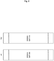
- the basic arrangement which is provided as a comparative arrangement has been chosen such that it resembles the structure of an arrangement which is typically used in the industry for a methanol synthesis plant, in which two reactors with one catalyst layer each are utilized, and as it is exemplarily described in the application WO 2011/101081 A1 .
- the basic arrangement two reactors 1 and 2 are utilized. In both reactors, the same catalyst material MegaMax® 800 with a pellet size of 6x4 mm is used.
- the first reactor, reactor 1 is configured as a water-cooled reactor (WCR - water cooled reactor), whereas the second reactor, reactor 2, is configured such that it resembles the temperature profile of a gas-cooled reactor (GCR - gas cooled reactor), which is known from the prior art.
- the schematic structure of the basic arrangement is depicted in fig. 2 . In the following tables, the measurement values of this basic arrangement are reproduced in the third column.
- m catalyst denotes the mass of the used catalyst material.
- T cool(first reactor) denotes the temperature of the water mantle in the area of the first catalyst layer.
- the recycle ratio RR denotes the ratio between fresh and reused, non-converted synthesis gas.
- GHSV denotes the gas hourly space velocity.
- T max denotes the maximum temperature occuring in the catalyst layers during the synthesis reaction.
- X CO_pp(first reactor) denotes the amount of converted carbon monoxide in the first reactor, wherein the first reactor in the examples according to the invention is the reactor in which the catalyst layers according to the invention are arranged.
- X CO2_pp(first reactor) denotes the amount of converted carbon dioxide in the first reactor.
- X CO_pp(all reactors) denotes the amount of converted carbon monoxide in all reactors in total.
- X CO2_pp all reactors denotes the amount of converted carbon dioxide in all reactors in total.
- STY first reactor denotes the specific product outputs or space-time-yield, i.e. the quantity of product formed in the first reactor per volume and time.
- STY all reactors denotes correspondingly the specific product output of all reactors. This nomenclature applies also to the following examples according to the invention. Thus, the basic arrangement with two reactors is compared with the arrangement according to the invention of multiple catalyst layers in one reactor.
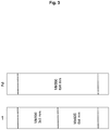
- the two catalyst layers are catalysts of the MegaMax® series, particularly MegaMax® 800 catalysts, wherein the catalysts have different pellet sizes. Other catalysts can also be utilized such as copper-based methanol synthesis catalysts.
- the first catalyst layer has a pellet size of 3x3 mm, wherein the second catalyst layer has a pellet size of 6x4 mm.
- Synthesis gas travels from the first catalyst layer to the second catalyst layer.
- the first catalyst layer has a higher activity than the second catalyst layer.
- a further reactor 2 which exhibits only one catalyst layer.
- This reactor only contains one catalyst with moderate activity (MegaMax® 800 with a pellet size of 6x4 mm).
- MegaMax® 800 with a pellet size of 6x4 mm.
- the structure corresponds to the structure which is depicted in fig. 2 .
- Fig. 4 shows a second arrangement according to the invention, in which only one reactor filled with catalyst is provided.
- This reactor is water-cooled.
- the arrangement corresponds to the arrangement which is shown in fig. 2 with the difference that, instead of the two reactors 1 and 2, only the water-cooled reactor 1 is filled with catalyst material, and reactor 2 remains empty.
- four catalyst layers are provided, wherein part of these catalysts are catalysts of the MegaMax® series.
- the layers are configured as a first layer of MegaMax® 800 with a pellet size of 6x4 mm and a relative layer thickness of 10%, in relation to the total thickness of all catalyst layers.
- the second layer is C79-5 with a pellet size of 5x5 mm and a relative layer thickness of 30%.
- the third layer is MegaMax® 800 with a pellet size of 6x4 mm with a relative layer thickness of 30%.
- the fourth layer is MegaMax® 800 with a pellet size of 3x3 mm with a relative layer thickness of 30%.
- other catalysts such as copper-based methanol synthesis catalysts can be utilized. The catalysts and pellet sizes are chosen such that the activity of the last catalyst layer is highest. The second layer has the lowest activity.
- the conversion of the carbon oxides and the specific product output in the arrangement according to the invention is enhanced compared to the basic arrangement by about 10% (CO) and 18% (CO 2 ). Also, due to the increased conversion of carbon oxides, the heat generation in the reactor is increased, which leads to a higher maximum temperature T max in the catalyst bed. Since only one reactor is used in the arrangement according to the invention, the specific product output of the whole plant is increased by about 115%.
- Table 2 4-layer catalyst bed - 1 reactor Basic arrangement - 1 catalyst - 2 reactors Unit m catalyst 1.5 2.8 Kg T cool(first reactor) 250 250 °C recycle ratio 1.6 1.6 - GHSV 15000 15000 h -1 T max 286.2 +/- 1.0 284.0 +/- 2.1 °C X CO_pp(first reactor) 79.7 +/- 1.0 69.8 +/- 1.2 % X CO2_pp(first reactor) 33.2 +/- 1.7 15.2 +/- 3.7 % X CO_pp(all reactors) - 86.3 +/- 1.2 % X CO2_pp(all reactors) - 2 5.0 +/- 6.9 % STY (first reactor) 2.06 +/- 0.03 1.70 +/- 0.06 kg/(l ⁇ h) STY (all reactors) - 0.96 +/- 0.05 kg/(l ⁇ h)
- a structural arrangement has been chosen, as is shown in fig. 4 .
- the synthesis reaction has been conducted at a lower temperature. This leads to a lower deactivation of the catalysts and therefore to a higher yield. It is assumed that the activity of the catalysts after 1000 hours of operation is about 10% higher than the activity of the catalysts in the basic arrangement.
- the conversion of carbon oxides increases in comparison to the basic arrangement by about 13% (CO) and 19% (CO 2 ), and the specific product output of the reactor by 22%.
- Table 3 4-layer catalyst bed - 1 reactor Basic arrangement - 1 catalyst - 2 reactors Unit m catalyst 1.5 2.8 Kg T cool(first reactor) 230 250 °C recycle ratio 1.6 1.6 - GHSV 15000 15000 h -1 T max 260.5 +/- 0.6 284.0 +/- 2.1 °C X CO_pp(first reactor) 82.4 +/- 0.6 69.8 +/- 1.2 % X CO2_pp(first reactor) 34.2 +/- 1.2 15.2 +/- 3.7 % X CO_pp(all reactors) - 86.3 +/- 1.2 % X CO2_pp(all reactors) - 2 5.0 +/- 6.9 % STY (first reactor) 2.07 +/- 0.04 1.70 +/- 0.06 kg/(l ⁇ h) STY (all reactors) - 0.96 +/- 0.05 kg/(l ⁇ h)
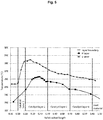
- Fig. 5 shows the temperature development within the catalyst layers during the synthesis reaction in the basic arrangement and in the arrangement which is shown in fig. 4 at a lower temperature regime (example 3).
Landscapes
- Chemical & Material Sciences (AREA)
- Organic Chemistry (AREA)
- Chemical Kinetics & Catalysis (AREA)
- Organic Low-Molecular-Weight Compounds And Preparation Thereof (AREA)
- Catalysts (AREA)
- Low-Molecular Organic Synthesis Reactions Using Catalysts (AREA)
Claims (4)
- Verfahren zur katalytischen Herstellung von Methanol aus Synthesegas, wobei das Verfahren die folgenden Schritte umfasst:Bereitstellen eines Reaktors;Anordnen von zumindest zwei Katalysatorschichten in dem Reaktor,wobei die erste Katalysatorschicht stromaufwärts und die zweite Katalysatorschicht stromabwärts angeordnet ist, und wobei die Aktivität der ersten Katalysatorschicht höher als die Aktivität der zweiten Katalysatorschicht ist;Zuführen von Synthesegas, das Wasserstoff und Kohlenstoffoxide umfasst, zum Reaktor,Umwandeln des Synthesegases im Reaktor unter Methanolsynthesebedingungen zu Methanol,Leiten des produzierten Methanols und des nicht umgewandelten Synthesegases aus dem Reaktor.
- Verfahren nach Anspruch 1, wobei der Reaktor ein wassergekühlter Reaktor ist und die Kühltemperatur zwischen 200°C und 260°C, bevorzugt zwischen 230°C und 250°C, liegt.
- Verfahren nach Anspruch 1 oder 2, wobei in dem Reaktor zumindest zwei weitere Katalysatorschichten angeordnet sind, wobei die weiteren Katalysatorschichten jeweils stromabwärts von der zweiten Katalysatorschicht angeordnet sind, und wobei die Aktivität der weiteren Katalysatorschichten zum stromabwärtigen Ende des Reaktors hin sukzessive zunimmt.
- Verfahren nach einem der Ansprüche 1 bis 3, wobei die Kühltemperatur und die Schichtdicke und die Aktivität der einzelnen Katalysatorschichten so gewählt wird, dass die resultierende Reaktionstemperatur im Reaktor ungefähr 260°C nicht überschreitet.
Priority Applications (1)
| Application Number | Priority Date | Filing Date | Title |
|---|---|---|---|
| PL18705374.9T PL3582886T5 (pl) | 2017-02-15 | 2018-02-13 | Sposób maksymalizowania wydajności metanolu przez zastosowanie warstw katalizatorowych |
Applications Claiming Priority (2)
| Application Number | Priority Date | Filing Date | Title |
|---|---|---|---|
| DE102017001520.1A DE102017001520A1 (de) | 2017-02-15 | 2017-02-15 | Reaktor und Verfahren zur Maximierung der Methanolausbeute durch Einsatz von Katalysatorschichten |
| PCT/EP2018/053518 WO2018149811A1 (en) | 2017-02-15 | 2018-02-13 | Reactor and method for maximizing methanol yield by using catalyst layers |
Publications (3)
| Publication Number | Publication Date |
|---|---|
| EP3582886A1 EP3582886A1 (de) | 2019-12-25 |
| EP3582886B1 true EP3582886B1 (de) | 2020-12-30 |
| EP3582886B2 EP3582886B2 (de) | 2023-07-12 |
Family
ID=61226573
Family Applications (1)
| Application Number | Title | Priority Date | Filing Date |
|---|---|---|---|
| EP18705374.9A Active EP3582886B2 (de) | 2017-02-15 | 2018-02-13 | Verfahren zur maximierung der methanolausbeute unter verwendung von katalysatorschichten |
Country Status (11)
| Country | Link |
|---|---|
| US (1) | US10737230B2 (de) |
| EP (1) | EP3582886B2 (de) |
| CN (2) | CN208532645U (de) |
| CA (1) | CA3050609C (de) |
| DE (1) | DE102017001520A1 (de) |
| DK (1) | DK3582886T4 (de) |
| MY (1) | MY188899A (de) |
| PL (1) | PL3582886T5 (de) |
| RU (1) | RU2728351C1 (de) |
| SA (1) | SA519402409B1 (de) |
| WO (1) | WO2018149811A1 (de) |
Families Citing this family (5)
| Publication number | Priority date | Publication date | Assignee | Title |
|---|---|---|---|---|
| EP4277736A1 (de) * | 2021-01-15 | 2023-11-22 | Cri Hf | Methanolsynthesereaktor |
| CN113926391A (zh) * | 2021-11-11 | 2022-01-14 | 四川天人能源科技有限公司 | 一种催化剂易热失活的放热催化反应改进工艺 |
| WO2024083780A1 (en) | 2022-10-18 | 2024-04-25 | Basf Se | Improved catalyst shapes for heat transfer and pressure-drop in the syngas conversion |
| CN116212752B (zh) * | 2023-04-04 | 2024-05-24 | 常州新日催化剂股份有限公司 | 一种低压型丁烷法顺酐催化剂的装填方法 |
| WO2025141140A1 (en) | 2023-12-29 | 2025-07-03 | Basf Se | Process for preparing an activated catalyst and process for preparing methanol using a co2-containing feed stream |
Citations (1)
| Publication number | Priority date | Publication date | Assignee | Title |
|---|---|---|---|---|
| US5827901A (en) | 1996-02-15 | 1998-10-27 | Metallgesellschaft Aktiengesellschaft | Process of producing methanol |
Family Cites Families (8)
| Publication number | Priority date | Publication date | Assignee | Title |
|---|---|---|---|---|
| DE1300917B (de) * | 1967-12-30 | 1969-08-14 | Metallgesellschaft Ag | Verfahren zur Herstellung von Methanol |
| IT1078798B (it) * | 1976-09-24 | 1985-05-08 | Tecnimont Spa | Reattore per reazioni esotermiche catalizzate |
| US4372920A (en) * | 1979-07-13 | 1983-02-08 | Ammonia Casale S.A. | Axial-radial reactor for heterogeneous synthesis |
| JP2560311B2 (ja) * | 1987-02-27 | 1996-12-04 | 三菱瓦斯化学株式会社 | メタノ−ルないし混合アルコ−ルの製造法 |
| EP0931586B1 (de) * | 1997-11-28 | 2005-03-16 | Ammonia Casale S.A. | Verfahren zur in-situ Modernisierung eines heterogenen exothermen Synthesereaktors |
| CN101670253A (zh) * | 2007-12-17 | 2010-03-17 | 亚申科技研发中心(上海)有限公司 | 实施放热催化工艺的方法及装置 |
| DE102010008857A1 (de) * | 2010-02-22 | 2011-08-25 | Lurgi GmbH, 60439 | Verfahren zur Herstellung von Methanol |
| CN107922297A (zh) * | 2015-08-12 | 2018-04-17 | 托普索公司 | 用于从低质量合成气生产甲醇的新方法 |
-
2017
- 2017-02-15 DE DE102017001520.1A patent/DE102017001520A1/de not_active Withdrawn
-
2018
- 2018-02-13 US US16/485,848 patent/US10737230B2/en active Active
- 2018-02-13 WO PCT/EP2018/053518 patent/WO2018149811A1/en not_active Ceased
- 2018-02-13 DK DK18705374.9T patent/DK3582886T4/da active
- 2018-02-13 PL PL18705374.9T patent/PL3582886T5/pl unknown
- 2018-02-13 CN CN201820258184.5U patent/CN208532645U/zh active Active
- 2018-02-13 CN CN201810149682.0A patent/CN108424351B/zh active Active
- 2018-02-13 EP EP18705374.9A patent/EP3582886B2/de active Active
- 2018-02-13 RU RU2019128573A patent/RU2728351C1/ru active
- 2018-02-13 CA CA3050609A patent/CA3050609C/en active Active
- 2018-02-13 MY MYPI2019004635A patent/MY188899A/en unknown
-
2019
- 2019-08-06 SA SA519402409A patent/SA519402409B1/ar unknown
Patent Citations (1)
| Publication number | Priority date | Publication date | Assignee | Title |
|---|---|---|---|---|
| US5827901A (en) | 1996-02-15 | 1998-10-27 | Metallgesellschaft Aktiengesellschaft | Process of producing methanol |
Non-Patent Citations (3)
| Title |
|---|
| "Ammonia Methanol Hydrogen Carbonmonoxide Modern Production Technologies", 1 January 1997, BRITISH SULPHUR PUBLISHING, article APPL MAX: "Methanol", pages: 1 - 5, XP055802049 |
| "Ullmann's Encyclopedia of Industrial Chemistry: Principles of chemical reaction engineering and plant design", 1 January 1992, article ANONYMOUS: "Industrial reactors", pages: 222 - 223, XP055849248 |
| RAHIMPOUR M. R., MOGHTADERI B., JAHANMIRI A., REZAIE N.: "Operability of an Industrial Methanol Synthesis Reactor with Mixtures of Fresh and Partially Deactivated Catalyst", CHEMICAL ENGINEERING & TECHNOLOGY, J. WILEY, vol. 28, no. 2, 1 February 2005 (2005-02-01), pages 226 - 234, XP055849241, ISSN: 0930-7516, DOI: 10.1002/ceat.200407062 |
Also Published As
| Publication number | Publication date |
|---|---|
| CN108424351A (zh) | 2018-08-21 |
| MY188899A (en) | 2022-01-13 |
| EP3582886B2 (de) | 2023-07-12 |
| CN208532645U (zh) | 2019-02-22 |
| WO2018149811A1 (en) | 2018-08-23 |
| US10737230B2 (en) | 2020-08-11 |
| CA3050609C (en) | 2021-07-13 |
| DE102017001520A1 (de) | 2018-08-16 |
| DK3582886T3 (da) | 2021-02-22 |
| PL3582886T5 (pl) | 2023-10-09 |
| RU2728351C1 (ru) | 2020-07-29 |
| CA3050609A1 (en) | 2018-08-23 |
| PL3582886T3 (pl) | 2021-08-02 |
| US20200001261A1 (en) | 2020-01-02 |
| DK3582886T4 (da) | 2023-08-07 |
| SA519402409B1 (ar) | 2022-11-10 |
| CN108424351B (zh) | 2023-02-17 |
| EP3582886A1 (de) | 2019-12-25 |
Similar Documents
| Publication | Publication Date | Title |
|---|---|---|
| EP3582886B2 (de) | Verfahren zur maximierung der methanolausbeute unter verwendung von katalysatorschichten | |
| US20080107585A1 (en) | Maximum reaction rate converter process for exothermic reactions | |
| EP2641889B1 (de) | Verfahren zur herstellung von methanol | |
| EP3922346B1 (de) | Reaktor mit katalysatorbehältern und verfahren zur verwendung desselben | |
| US20100189633A1 (en) | Method for producing chlorine by gas phase oxidation | |
| EP2818458B1 (de) | Verfahren zur Herstellung von Methanol in Parallelreaktoren | |
| WO2014131435A1 (en) | Reactor for an auto-poisoning proces | |
| EP2450100A1 (de) | Verfahren und Anlage zur Herstellung von Methanol mit isothermalen Katalysatorbetten | |
| KR102908238B1 (ko) | 에탄 odh 공정에서 아세트산 생산의 제한 | |
| EP1966348B1 (de) | Verfahren zur herstellung von in kondensierter phase vorliegendem produkt aus einem oder mehreren in der gasphase vorliegenden reaktanten | |
| US7678343B2 (en) | Metallic monolith catalyst support for selective gas phase reactions in tubular fixed bed reactors | |
| EP1904429B1 (de) | Verfahren zur herstellung ungesättigter säure in einem katalytischen festbetteiloxidationsreaktor mit hoher effizienz | |
| US9073034B2 (en) | Efficient fixed bed platform for production of ethylene oxide by partial oxidation of ethylene using catalyst of wide selectivity | |
| US20110060149A1 (en) | Process for preparing ethylene oxide | |
| EP1110605B1 (de) | Verwendung einer monolitischen metallischen Katalysatorträger zur selektiven Gasphasenreaktionen | |
| JP7843719B2 (ja) | メタネーション反応装置及びメタネーション反応方法 | |
| US20250059029A1 (en) | Systems and methods for producing hydrogen gas from water and methane | |
| WO2003035544A1 (en) | Compact shift reactor | |
| Crane | Overview of catalytic reactor design | |
| JP2013091639A (ja) | プロピレンオキサイドの製造方法 |
Legal Events
| Date | Code | Title | Description |
|---|---|---|---|
| STAA | Information on the status of an ep patent application or granted ep patent |
Free format text: STATUS: UNKNOWN |
|
| STAA | Information on the status of an ep patent application or granted ep patent |
Free format text: STATUS: THE INTERNATIONAL PUBLICATION HAS BEEN MADE |
|
| PUAI | Public reference made under article 153(3) epc to a published international application that has entered the european phase |
Free format text: ORIGINAL CODE: 0009012 |
|
| STAA | Information on the status of an ep patent application or granted ep patent |
Free format text: STATUS: REQUEST FOR EXAMINATION WAS MADE |
|
| 17P | Request for examination filed |
Effective date: 20190912 |
|
| AK | Designated contracting states |
Kind code of ref document: A1 Designated state(s): AL AT BE BG CH CY CZ DE DK EE ES FI FR GB GR HR HU IE IS IT LI LT LU LV MC MK MT NL NO PL PT RO RS SE SI SK SM TR |
|
| AX | Request for extension of the european patent |
Extension state: BA ME |
|
| RIN1 | Information on inventor provided before grant (corrected) |
Inventor name: KAISER, MARKUS Inventor name: SCHUHMANN, TIMM Inventor name: WERNER, SEBASTIAN Inventor name: FREUND, HANNSJOERG Inventor name: HENKEL, TOBIAS Inventor name: FRIND, ROBERT Inventor name: SEUFFERT, WOLFGANG |
|
| DAV | Request for validation of the european patent (deleted) | ||
| DAX | Request for extension of the european patent (deleted) | ||
| GRAP | Despatch of communication of intention to grant a patent |
Free format text: ORIGINAL CODE: EPIDOSNIGR1 |
|
| STAA | Information on the status of an ep patent application or granted ep patent |
Free format text: STATUS: GRANT OF PATENT IS INTENDED |
|
| INTG | Intention to grant announced |
Effective date: 20200820 |
|
| GRAS | Grant fee paid |
Free format text: ORIGINAL CODE: EPIDOSNIGR3 |
|
| GRAA | (expected) grant |
Free format text: ORIGINAL CODE: 0009210 |
|
| STAA | Information on the status of an ep patent application or granted ep patent |
Free format text: STATUS: THE PATENT HAS BEEN GRANTED |
|
| AK | Designated contracting states |
Kind code of ref document: B1 Designated state(s): AL AT BE BG CH CY CZ DE DK EE ES FI FR GB GR HR HU IE IS IT LI LT LU LV MC MK MT NL NO PL PT RO RS SE SI SK SM TR |
|
| REG | Reference to a national code |
Ref country code: GB Ref legal event code: FG4D |
|
| REG | Reference to a national code |
Ref country code: DE Ref legal event code: R096 Ref document number: 602018011349 Country of ref document: DE |
|
| REG | Reference to a national code |
Ref country code: AT Ref legal event code: REF Ref document number: 1349387 Country of ref document: AT Kind code of ref document: T Effective date: 20210115 |
|
| REG | Reference to a national code |
Ref country code: IE Ref legal event code: FG4D |
|
| REG | Reference to a national code |
Ref country code: DK Ref legal event code: T3 Effective date: 20210217 |
|
| REG | Reference to a national code |
Ref country code: NL Ref legal event code: FP |
|
| REG | Reference to a national code |
Ref country code: SE Ref legal event code: TRGR |
|
| PG25 | Lapsed in a contracting state [announced via postgrant information from national office to epo] |
Ref country code: FI Free format text: LAPSE BECAUSE OF FAILURE TO SUBMIT A TRANSLATION OF THE DESCRIPTION OR TO PAY THE FEE WITHIN THE PRESCRIBED TIME-LIMIT Effective date: 20201230 Ref country code: RS Free format text: LAPSE BECAUSE OF FAILURE TO SUBMIT A TRANSLATION OF THE DESCRIPTION OR TO PAY THE FEE WITHIN THE PRESCRIBED TIME-LIMIT Effective date: 20201230 Ref country code: GR Free format text: LAPSE BECAUSE OF FAILURE TO SUBMIT A TRANSLATION OF THE DESCRIPTION OR TO PAY THE FEE WITHIN THE PRESCRIBED TIME-LIMIT Effective date: 20210331 |
|
| REG | Reference to a national code |
Ref country code: AT Ref legal event code: MK05 Ref document number: 1349387 Country of ref document: AT Kind code of ref document: T Effective date: 20201230 |
|
| PG25 | Lapsed in a contracting state [announced via postgrant information from national office to epo] |
Ref country code: LV Free format text: LAPSE BECAUSE OF FAILURE TO SUBMIT A TRANSLATION OF THE DESCRIPTION OR TO PAY THE FEE WITHIN THE PRESCRIBED TIME-LIMIT Effective date: 20201230 Ref country code: BG Free format text: LAPSE BECAUSE OF FAILURE TO SUBMIT A TRANSLATION OF THE DESCRIPTION OR TO PAY THE FEE WITHIN THE PRESCRIBED TIME-LIMIT Effective date: 20210330 |
|
| REG | Reference to a national code |
Ref country code: NO Ref legal event code: T2 Effective date: 20201230 |
|
| PG25 | Lapsed in a contracting state [announced via postgrant information from national office to epo] |
Ref country code: HR Free format text: LAPSE BECAUSE OF FAILURE TO SUBMIT A TRANSLATION OF THE DESCRIPTION OR TO PAY THE FEE WITHIN THE PRESCRIBED TIME-LIMIT Effective date: 20201230 |
|
| REG | Reference to a national code |
Ref country code: LT Ref legal event code: MG9D |
|
| PG25 | Lapsed in a contracting state [announced via postgrant information from national office to epo] |
Ref country code: CZ Free format text: LAPSE BECAUSE OF FAILURE TO SUBMIT A TRANSLATION OF THE DESCRIPTION OR TO PAY THE FEE WITHIN THE PRESCRIBED TIME-LIMIT Effective date: 20201230 Ref country code: EE Free format text: LAPSE BECAUSE OF FAILURE TO SUBMIT A TRANSLATION OF THE DESCRIPTION OR TO PAY THE FEE WITHIN THE PRESCRIBED TIME-LIMIT Effective date: 20201230 Ref country code: SK Free format text: LAPSE BECAUSE OF FAILURE TO SUBMIT A TRANSLATION OF THE DESCRIPTION OR TO PAY THE FEE WITHIN THE PRESCRIBED TIME-LIMIT Effective date: 20201230 Ref country code: LT Free format text: LAPSE BECAUSE OF FAILURE TO SUBMIT A TRANSLATION OF THE DESCRIPTION OR TO PAY THE FEE WITHIN THE PRESCRIBED TIME-LIMIT Effective date: 20201230 Ref country code: RO Free format text: LAPSE BECAUSE OF FAILURE TO SUBMIT A TRANSLATION OF THE DESCRIPTION OR TO PAY THE FEE WITHIN THE PRESCRIBED TIME-LIMIT Effective date: 20201230 Ref country code: PT Free format text: LAPSE BECAUSE OF FAILURE TO SUBMIT A TRANSLATION OF THE DESCRIPTION OR TO PAY THE FEE WITHIN THE PRESCRIBED TIME-LIMIT Effective date: 20210430 |
|
| PG25 | Lapsed in a contracting state [announced via postgrant information from national office to epo] |
Ref country code: AT Free format text: LAPSE BECAUSE OF FAILURE TO SUBMIT A TRANSLATION OF THE DESCRIPTION OR TO PAY THE FEE WITHIN THE PRESCRIBED TIME-LIMIT Effective date: 20201230 |
|
| REG | Reference to a national code |
Ref country code: DE Ref legal event code: R026 Ref document number: 602018011349 Country of ref document: DE |
|
| PG25 | Lapsed in a contracting state [announced via postgrant information from national office to epo] |
Ref country code: MC Free format text: LAPSE BECAUSE OF FAILURE TO SUBMIT A TRANSLATION OF THE DESCRIPTION OR TO PAY THE FEE WITHIN THE PRESCRIBED TIME-LIMIT Effective date: 20201230 |
|
| PLBI | Opposition filed |
Free format text: ORIGINAL CODE: 0009260 |
|
| PLAX | Notice of opposition and request to file observation + time limit sent |
Free format text: ORIGINAL CODE: EPIDOSNOBS2 |
|
| PG25 | Lapsed in a contracting state [announced via postgrant information from national office to epo] |
Ref country code: CH Free format text: LAPSE BECAUSE OF NON-PAYMENT OF DUE FEES Effective date: 20210228 Ref country code: AL Free format text: LAPSE BECAUSE OF FAILURE TO SUBMIT A TRANSLATION OF THE DESCRIPTION OR TO PAY THE FEE WITHIN THE PRESCRIBED TIME-LIMIT Effective date: 20201230 Ref country code: LI Free format text: LAPSE BECAUSE OF NON-PAYMENT OF DUE FEES Effective date: 20210228 Ref country code: LU Free format text: LAPSE BECAUSE OF NON-PAYMENT OF DUE FEES Effective date: 20210213 |
|
| 26 | Opposition filed |
Opponent name: JOHNSON MATTHEY PUBLIC LIMITED COMPANY Effective date: 20210929 |
|
| PG25 | Lapsed in a contracting state [announced via postgrant information from national office to epo] |
Ref country code: FR Free format text: LAPSE BECAUSE OF NON-PAYMENT OF DUE FEES Effective date: 20210228 Ref country code: ES Free format text: LAPSE BECAUSE OF FAILURE TO SUBMIT A TRANSLATION OF THE DESCRIPTION OR TO PAY THE FEE WITHIN THE PRESCRIBED TIME-LIMIT Effective date: 20201230 Ref country code: IE Free format text: LAPSE BECAUSE OF NON-PAYMENT OF DUE FEES Effective date: 20210213 |
|
| PLBB | Reply of patent proprietor to notice(s) of opposition received |
Free format text: ORIGINAL CODE: EPIDOSNOBS3 |
|
| PG25 | Lapsed in a contracting state [announced via postgrant information from national office to epo] |
Ref country code: SI Free format text: LAPSE BECAUSE OF FAILURE TO SUBMIT A TRANSLATION OF THE DESCRIPTION OR TO PAY THE FEE WITHIN THE PRESCRIBED TIME-LIMIT Effective date: 20201230 |
|
| RAP4 | Party data changed (patent owner data changed or rights of a patent transferred) |
Owner name: L'AIR LIQUIDE, SOCIETE ANONYME POUR L'ETUDE ET L'EXPLOITATION DES PROCEDES GEORGES CLAUDE Owner name: CLARIANT INTERNATIONAL LTD |
|
| PUAH | Patent maintained in amended form |
Free format text: ORIGINAL CODE: 0009272 |
|
| STAA | Information on the status of an ep patent application or granted ep patent |
Free format text: STATUS: PATENT MAINTAINED AS AMENDED |
|
| P01 | Opt-out of the competence of the unified patent court (upc) registered |
Effective date: 20230522 |
|
| PG25 | Lapsed in a contracting state [announced via postgrant information from national office to epo] |
Ref country code: CY Free format text: LAPSE BECAUSE OF FAILURE TO SUBMIT A TRANSLATION OF THE DESCRIPTION OR TO PAY THE FEE WITHIN THE PRESCRIBED TIME-LIMIT Effective date: 20201230 |
|
| 27A | Patent maintained in amended form |
Effective date: 20230712 |
|
| AK | Designated contracting states |
Kind code of ref document: B2 Designated state(s): AL AT BE BG CH CY CZ DE DK EE ES FI FR GB GR HR HU IE IS IT LI LT LU LV MC MK MT NL NO PL PT RO RS SE SI SK SM TR |
|
| REG | Reference to a national code |
Ref country code: DE Ref legal event code: R102 Ref document number: 602018011349 Country of ref document: DE |
|
| PG25 | Lapsed in a contracting state [announced via postgrant information from national office to epo] |
Ref country code: SM Free format text: LAPSE BECAUSE OF FAILURE TO SUBMIT A TRANSLATION OF THE DESCRIPTION OR TO PAY THE FEE WITHIN THE PRESCRIBED TIME-LIMIT Effective date: 20201230 Ref country code: HU Free format text: LAPSE BECAUSE OF FAILURE TO SUBMIT A TRANSLATION OF THE DESCRIPTION OR TO PAY THE FEE WITHIN THE PRESCRIBED TIME-LIMIT; INVALID AB INITIO Effective date: 20180213 |
|
| REG | Reference to a national code |
Ref country code: DK Ref legal event code: T4 Effective date: 20230801 |
|
| REG | Reference to a national code |
Ref country code: NL Ref legal event code: FP |
|
| REG | Reference to a national code |
Ref country code: NO Ref legal event code: T2 Effective date: 20201230 |
|
| REG | Reference to a national code |
Ref country code: SE Ref legal event code: RPEO |
|
| PG25 | Lapsed in a contracting state [announced via postgrant information from national office to epo] |
Ref country code: MK Free format text: LAPSE BECAUSE OF FAILURE TO SUBMIT A TRANSLATION OF THE DESCRIPTION OR TO PAY THE FEE WITHIN THE PRESCRIBED TIME-LIMIT Effective date: 20201230 |
|
| PG25 | Lapsed in a contracting state [announced via postgrant information from national office to epo] |
Ref country code: TR Free format text: LAPSE BECAUSE OF FAILURE TO SUBMIT A TRANSLATION OF THE DESCRIPTION OR TO PAY THE FEE WITHIN THE PRESCRIBED TIME-LIMIT Effective date: 20201230 |
|
| PG25 | Lapsed in a contracting state [announced via postgrant information from national office to epo] |
Ref country code: MT Free format text: LAPSE BECAUSE OF FAILURE TO SUBMIT A TRANSLATION OF THE DESCRIPTION OR TO PAY THE FEE WITHIN THE PRESCRIBED TIME-LIMIT Effective date: 20201230 |
|
| PGFP | Annual fee paid to national office [announced via postgrant information from national office to epo] |
Ref country code: NL Payment date: 20260218 Year of fee payment: 9 |
|
| PGFP | Annual fee paid to national office [announced via postgrant information from national office to epo] |
Ref country code: SE Payment date: 20260218 Year of fee payment: 9 |
|
| PGFP | Annual fee paid to national office [announced via postgrant information from national office to epo] |
Ref country code: GB Payment date: 20260219 Year of fee payment: 9 |
|
| PGFP | Annual fee paid to national office [announced via postgrant information from national office to epo] |
Ref country code: NO Payment date: 20260217 Year of fee payment: 9 Ref country code: DE Payment date: 20260225 Year of fee payment: 9 Ref country code: DK Payment date: 20260217 Year of fee payment: 9 |
|
| PGFP | Annual fee paid to national office [announced via postgrant information from national office to epo] |
Ref country code: BE Payment date: 20260218 Year of fee payment: 9 Ref country code: IT Payment date: 20260227 Year of fee payment: 9 |
|
| PGFP | Annual fee paid to national office [announced via postgrant information from national office to epo] |
Ref country code: IS Payment date: 20260218 Year of fee payment: 9 |
|
| PGFP | Annual fee paid to national office [announced via postgrant information from national office to epo] |
Ref country code: PL Payment date: 20260108 Year of fee payment: 9 |