EP3582865B1 - Sensing apparatus and method - Google Patents
Sensing apparatus and method Download PDFInfo
- Publication number
- EP3582865B1 EP3582865B1 EP18705468.9A EP18705468A EP3582865B1 EP 3582865 B1 EP3582865 B1 EP 3582865B1 EP 18705468 A EP18705468 A EP 18705468A EP 3582865 B1 EP3582865 B1 EP 3582865B1
- Authority
- EP
- European Patent Office
- Prior art keywords
- controller
- biofeedback
- user
- information
- sensors
- Prior art date
- Legal status (The legal status is an assumption and is not a legal conclusion. Google has not performed a legal analysis and makes no representation as to the accuracy of the status listed.)
- Active
Links
Images


Classifications
-
- A—HUMAN NECESSITIES
- A63—SPORTS; GAMES; AMUSEMENTS
- A63F—CARD, BOARD, OR ROULETTE GAMES; INDOOR GAMES USING SMALL MOVING PLAYING BODIES; VIDEO GAMES; GAMES NOT OTHERWISE PROVIDED FOR
- A63F13/00—Video games, i.e. games using an electronically generated display having two or more dimensions
- A63F13/20—Input arrangements for video game devices
-
- A—HUMAN NECESSITIES
- A63—SPORTS; GAMES; AMUSEMENTS
- A63F—CARD, BOARD, OR ROULETTE GAMES; INDOOR GAMES USING SMALL MOVING PLAYING BODIES; VIDEO GAMES; GAMES NOT OTHERWISE PROVIDED FOR
- A63F13/00—Video games, i.e. games using an electronically generated display having two or more dimensions
- A63F13/20—Input arrangements for video game devices
- A63F13/21—Input arrangements for video game devices characterised by their sensors, purposes or types
- A63F13/212—Input arrangements for video game devices characterised by their sensors, purposes or types using sensors worn by the player, e.g. for measuring heart beat or leg activity
-
- A—HUMAN NECESSITIES
- A63—SPORTS; GAMES; AMUSEMENTS
- A63F—CARD, BOARD, OR ROULETTE GAMES; INDOOR GAMES USING SMALL MOVING PLAYING BODIES; VIDEO GAMES; GAMES NOT OTHERWISE PROVIDED FOR
- A63F13/00—Video games, i.e. games using an electronically generated display having two or more dimensions
- A63F13/20—Input arrangements for video game devices
- A63F13/21—Input arrangements for video game devices characterised by their sensors, purposes or types
-
- A—HUMAN NECESSITIES
- A63—SPORTS; GAMES; AMUSEMENTS
- A63F—CARD, BOARD, OR ROULETTE GAMES; INDOOR GAMES USING SMALL MOVING PLAYING BODIES; VIDEO GAMES; GAMES NOT OTHERWISE PROVIDED FOR
- A63F13/00—Video games, i.e. games using an electronically generated display having two or more dimensions
- A63F13/20—Input arrangements for video game devices
- A63F13/23—Input arrangements for video game devices for interfacing with the game device, e.g. specific interfaces between game controller and console
-
- A—HUMAN NECESSITIES
- A63—SPORTS; GAMES; AMUSEMENTS
- A63F—CARD, BOARD, OR ROULETTE GAMES; INDOOR GAMES USING SMALL MOVING PLAYING BODIES; VIDEO GAMES; GAMES NOT OTHERWISE PROVIDED FOR
- A63F13/00—Video games, i.e. games using an electronically generated display having two or more dimensions
- A63F13/20—Input arrangements for video game devices
- A63F13/24—Constructional details thereof, e.g. game controllers with detachable joystick handles
-
- A—HUMAN NECESSITIES
- A63—SPORTS; GAMES; AMUSEMENTS
- A63F—CARD, BOARD, OR ROULETTE GAMES; INDOOR GAMES USING SMALL MOVING PLAYING BODIES; VIDEO GAMES; GAMES NOT OTHERWISE PROVIDED FOR
- A63F13/00—Video games, i.e. games using an electronically generated display having two or more dimensions
- A63F13/40—Processing input control signals of video game devices, e.g. signals generated by the player or derived from the environment
- A63F13/42—Processing input control signals of video game devices, e.g. signals generated by the player or derived from the environment by mapping the input signals into game commands, e.g. mapping the displacement of a stylus on a touch screen to the steering angle of a virtual vehicle
-
- A—HUMAN NECESSITIES
- A63—SPORTS; GAMES; AMUSEMENTS
- A63F—CARD, BOARD, OR ROULETTE GAMES; INDOOR GAMES USING SMALL MOVING PLAYING BODIES; VIDEO GAMES; GAMES NOT OTHERWISE PROVIDED FOR
- A63F13/00—Video games, i.e. games using an electronically generated display having two or more dimensions
- A63F13/40—Processing input control signals of video game devices, e.g. signals generated by the player or derived from the environment
- A63F13/42—Processing input control signals of video game devices, e.g. signals generated by the player or derived from the environment by mapping the input signals into game commands, e.g. mapping the displacement of a stylus on a touch screen to the steering angle of a virtual vehicle
- A63F13/424—Processing input control signals of video game devices, e.g. signals generated by the player or derived from the environment by mapping the input signals into game commands, e.g. mapping the displacement of a stylus on a touch screen to the steering angle of a virtual vehicle involving acoustic input signals, e.g. by using the results of pitch or rhythm extraction or voice recognition
-
- A—HUMAN NECESSITIES
- A63—SPORTS; GAMES; AMUSEMENTS
- A63F—CARD, BOARD, OR ROULETTE GAMES; INDOOR GAMES USING SMALL MOVING PLAYING BODIES; VIDEO GAMES; GAMES NOT OTHERWISE PROVIDED FOR
- A63F13/00—Video games, i.e. games using an electronically generated display having two or more dimensions
- A63F13/90—Constructional details or arrangements of video game devices not provided for in groups A63F13/20 or A63F13/25, e.g. housing, wiring, connections or cabinets
- A63F13/92—Video game devices specially adapted to be hand-held while playing
-
- A—HUMAN NECESSITIES
- A63—SPORTS; GAMES; AMUSEMENTS
- A63F—CARD, BOARD, OR ROULETTE GAMES; INDOOR GAMES USING SMALL MOVING PLAYING BODIES; VIDEO GAMES; GAMES NOT OTHERWISE PROVIDED FOR
- A63F13/00—Video games, i.e. games using an electronically generated display having two or more dimensions
- A63F13/90—Constructional details or arrangements of video game devices not provided for in groups A63F13/20 or A63F13/25, e.g. housing, wiring, connections or cabinets
- A63F13/98—Accessories, i.e. detachable arrangements optional for the use of the video game device, e.g. grip supports of game controllers
-
- G—PHYSICS
- G06—COMPUTING OR CALCULATING; COUNTING
- G06F—ELECTRIC DIGITAL DATA PROCESSING
- G06F3/00—Input arrangements for transferring data to be processed into a form capable of being handled by the computer; Output arrangements for transferring data from processing unit to output unit, e.g. interface arrangements
- G06F3/01—Input arrangements or combined input and output arrangements for interaction between user and computer
- G06F3/011—Arrangements for interaction with the human body, e.g. for user immersion in virtual reality
- G06F3/015—Input arrangements based on nervous system activity detection, e.g. brain waves [EEG] detection, electromyograms [EMG] detection, electrodermal response detection
-
- G—PHYSICS
- G06—COMPUTING OR CALCULATING; COUNTING
- G06F—ELECTRIC DIGITAL DATA PROCESSING
- G06F3/00—Input arrangements for transferring data to be processed into a form capable of being handled by the computer; Output arrangements for transferring data from processing unit to output unit, e.g. interface arrangements
- G06F3/01—Input arrangements or combined input and output arrangements for interaction between user and computer
- G06F3/02—Input arrangements using manually operated switches, e.g. using keyboards or dials
- G06F3/0202—Constructional details or processes of manufacture of the input device
- G06F3/0219—Special purpose keyboards
-
- G—PHYSICS
- G06—COMPUTING OR CALCULATING; COUNTING
- G06F—ELECTRIC DIGITAL DATA PROCESSING
- G06F3/00—Input arrangements for transferring data to be processed into a form capable of being handled by the computer; Output arrangements for transferring data from processing unit to output unit, e.g. interface arrangements
- G06F3/01—Input arrangements or combined input and output arrangements for interaction between user and computer
- G06F3/03—Arrangements for converting the position or the displacement of a member into a coded form
- G06F3/033—Pointing devices displaced or positioned by the user, e.g. mice, trackballs, pens or joysticks; Accessories therefor
- G06F3/038—Control and interface arrangements therefor, e.g. drivers or device-embedded control circuitry
-
- G—PHYSICS
- G06—COMPUTING OR CALCULATING; COUNTING
- G06F—ELECTRIC DIGITAL DATA PROCESSING
- G06F3/00—Input arrangements for transferring data to be processed into a form capable of being handled by the computer; Output arrangements for transferring data from processing unit to output unit, e.g. interface arrangements
- G06F3/01—Input arrangements or combined input and output arrangements for interaction between user and computer
- G06F3/03—Arrangements for converting the position or the displacement of a member into a coded form
- G06F3/033—Pointing devices displaced or positioned by the user, e.g. mice, trackballs, pens or joysticks; Accessories therefor
- G06F3/038—Control and interface arrangements therefor, e.g. drivers or device-embedded control circuitry
- G06F3/0383—Signal control means within the pointing device
Definitions
- This disclosure relates to a sensing method and apparatus.
- the present disclosure relates to sensor arrangements that add functionality to existing peripherals, rather than being provided separately as an entirely new peripheral. This may provide a cheaper alternative to purchasing specialised peripherals, and thus increases the chance that a user will purchase equipment to enable the additional functionality associated with the sensors.
- An example of a sensor that provides a new input that could be utilised to tailor content for users is one that measures electrodermal activity (EDA).
- EDA electrodermal activity
- Such sensors are operable to measure electrical conductance or voltage between two points - in this case, between two areas of a user's skin. Active sensors apply a small current to the user's skin in order to detect the conductance, while passive sensors measure a voltage without applying a current by use of a voltage amplifier.
- Such sensors may measure Galvanic Skin Resistance (GSR) and/or Galvanic Skin Potential (GSP). These measurements may vary in dependence upon a number of factors, such as how active a wearer's sweat glands are.
- GSR Galvanic Skin Resistance
- GSP Galvanic Skin Potential
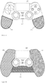
- FIGs 1A and 1B schematically illustrate a Sony@ DualShock® 4 controller that has been equipped with supplementary sensors.
- the use of the sensors with this controller is exemplary only, of course, and it should be appreciated that any type of videogame controller may be suitable for use with additional sensors.
- a particular biofeedback sensor attachment for a controller may be considered appropriate if it comprises one or more sensors arranged such that at least one sensor is in contact with a user's hand during conventional use of the controller. In embodiments, these sensors may be arranged on one or more sleeves that enclose at least a portion of the controller.
- FIG 1A shows an embodiment in which a controller 100 has been fitted with a pair of sleeves 110 and 120 that fit over the arms of the controller 100.
- the sleeves 110 and 120 comprise sensors that are suitable for measuring EDA via a user's hands.
- the sleeves provide a suitably large contact area with the user's hands whilst not extensively modifying the shape of the controller 100. It is apparent that only one of these sleeves need be provided, as the EDA may be measurable from either hand independently; however, providing a second sensor may help improve the accuracy of measurements.
- Figure 1B illustrates an embodiment in which a more extensive sensing apparatus is provided.
- the sensing apparatus illustrated in Figure 1B is provided in 3 parts, each of which may be provided individually or in conjunction with any of the others.
- the left- and right-hand portions 130 and 140 function similarly to the sleeves 110 and 120 of Figure 1A , but provide a much greater coverage of the controller 100.
- the increased size of the portions 130 and 140 relative to the sleeves 110 and 120 may allow for the use of larger and/or a greater number of sensors. This may improve the accuracy of measurements, due to an increased contact area with the user's skin, or simply ensure that a measurement is always able to be made during use regardless of how the user holds the controller.
- sleeve 110, 120 forms a detachable first part of larger sleeve 130, 140.
- the sleeves may attach via a Velcro ® or other attachment method, or may be moulded with respect to the controller so that they fit adjacent to one another. Alternatively or on addition they may respectively attach via a mutual sensor control unit 150 (discussed later herein).
- the sensors of the modular sleeves may be electrically independent or electrically connect to each other either directly or via the sensor control unit to form a larger sensor system.
- Sensors for measuring EDA generally comprise a pair of electrodes which, when in use, are in electrical contact via the user's body.
- each sleeve could comprise one or more electrodes; if each sleeve only comprises a single electrode, it may be necessary to provide more than one sleeve to be able to perform any detection, for example with one sleeve on each handle of a two handed-controller, and/or in a modular fashion as described above. If the electrodes are electrically isolated from one another, it may be possible to arrange a large number of electrodes on a device so as to ensure that a user makes contact with the electrodes no matter their hand size or grip style or the like.
- Sensors could also be provided over commonly-used buttons, or buttons on which the user rests their fingers, rather than (or in addition to those) on the body of the controller. While this means that contact with the sensors may be intermittent, the contact may still be enough to enable measurements to be made. Placing sensors on the buttons may be advantageous in that the user's comfort when holding the controller may be impacted to a lesser degree - generally users are used to the feel of a controller in their hand and so even small changes may make the controller feel unwieldy or uncomfortable. It may therefore be advantageous to ensure that changes to the controller are reduced where possible.
- sensors may be provided that clip onto the controller (or are otherwise affixed) that may be affixed to a user's hands or fingers via a strap. These sensors may be instead of the sleeve-type arrangement described above, or in addition. While the provision of such sensors may be advantageous in that they provide a constant contact with the user's skin, the user may regard this as being more invasive than a sleeve-type arrangement as discussed above in which no additional components have to be worn by a user.
- each sensor 130 and 140 may be associated with their own sensor control unit 150.
- Figure 2 schematically illustrates a sensing arrangement in which the sensors 130 and 140 communicate with the sensor control unit 150.
- the sensor control unit 150 is operable to perform any appropriate processing on the collected biofeedback information, and then transmit this information.
- the sensor control unit 150 may comprise a sensor input unit 151, an output unit 152, a power supply 153 and a processor 154.
- the sensors 130 and 140 are not necessarily limited to those that measure EDA; alternative or additional sensors may be provided.
- additional sensors may be provided that are able to refine measurements of a user's emotional state or help to characterise the emotion that is causing the measured changes in the user's emotional state.
- the sleeves could further comprise one or more heartrate monitors to provide further biofeedback.
- the sensor input unit 151 is operable to receive inputs comprising biofeedback information from the sensors 130 and 140, for example biofeedback information comprising electrodermal activity measurements or heart rate measurements. These measurements may be transmitted immediately, via the output unit 152, or may be first subjected to processing by the processor 154.
- the output unit 152 is operable to output information about measurements made by the one or more sensors.
- the output unit 152 may comprise any suitable wired or wireless transmitter, for example a USB cable or Bluetooth® transmitter respectively.
- the output unit 152 is operable to provide sensor information to the controller 100 which may then transmit this information to an associated games console (or the like) using its own wired or wireless connection.
- the output unit 152 may comprise its own wired or wireless transmitter for outputting information to the processing device associated with the controller directly.
- the processor 154 Before providing the sensor results to the output unit, they may be processed by the processor 154 in order to provide a more suitable output.
- the power supply 153 may provide power to at least one of the sensors 130/140 and/or the processor 154.
- the power supply 153 may comprise a battery, a connection to a mains adaptor, a connection to the controller 100 (for example via a port 102), or any other appropriate source of power.
- the processor 154 is operable to perform processing on the measurements obtained by the sensors, before they are output by the output unit 152. For example, rather than outputting raw sensor data, the data could be processed to generate a binary determination of whether or not the user is experiencing an emotional reaction to a game by comparing sensor values to calibration values. Alternatively, a graduated response could be provided such that a user's reaction is characterised by a response 'rating' corresponding to the severity of the user's reaction to the content displayed. Alternatively, or in addition, the processor 154 could perform processing so as to cause the output unit 152 to only provide an output when there is a change in the level of the user's emotional response.
- a processor of the controller may perform appropriate processing of the data (for example D/A conversion), and/or a processor of the receiving videogame console may perform appropriate processing, such as for example the binary determination described above.
- the sensing arrangement itself may not require a processor at all, or only an integrated circuit to perform basic signal processing functions. References herein to the processor 154 thus also encompass reference to a processor of the controller and/or videogame console where applicable.
- FIGS 1C and 1D illustrate an embodiment in which the sleeves 110, 120 (or equally sleeves 130, 140) of the sensing apparatus are integral with a sensor control unit 150, which comprises a connector to a PS4 extension port (but again could equally be a micro USB port, or in principle any port of the controller).
- the sensor control unit may also comprise a through-port to allow other peripherals that would otherwise use the port to be attached. It will be appreciated that at least some of the structural support for the sensing apparatus may be provided by the controller itself when the sensing apparatus is plugged into the port and in position, and hence the sleeves and connecting portion to the sensor control unit can be thin, lightweight and hence unobtrusive.
- the sleeves are shown optionally as half-sleeves that only cover the rear of the controller handles - designs appropriate to a particular controller can be envisaged by the skilled person.
- potentially only one sleeve may be required, and this may not necessarily be positioned on a handle of the controller as long as the user will regularly come into contact with it during normal user (e.g. on a region 110' of the back of the controller where a user rests one or more fingertips).
- power may be drawn from the port 102 to supply the sensor(s) and also any processing performed by the sensor control unit.
- the sensor(s) may be digitised by the controller for wireless communication
- raw input or a very simple modulation of an appropriate signal by that raw input, may be sufficient to enable the data to be transmitted via the controller back to the videogame console for further processing, without the need for a processor, or only a very simple one, in the sensor control unit itself.
- Figure 3 schematically illustrates a data format for communicating biofeedback information to a processing device.
- Context information 300 comprises information that identifies the data as relating to biofeedback. While this is shown as a separate header, this information could be included with the biofeedback information 310 or could be inherent, for example, in where the biofeedback information is located within a more general data stream.
- the biofeedback information 310 comprises raw or processed data about the user's reactions, such as heart rate data or measurements of EDA. As noted above, this data could be used to provide regular updates of measured values (such as a new measurement every second) or could communicate when changes to the measurements occur.
- this information may comprise a single number that indicates a user's emotional arousal; for example, five could be a base value and a range of zero to ten could be used to indicate deviations from this. This may be advantageous for reducing the amount of data that is communicated relative to a transmission of the raw biofeedback information.
- one or more new controller inputs could be defined at a system level that do not have corresponding physical buttons on the controller. These inputs could then only be used by devices such as the biofeedback sensors, thus preventing a user from pressing such a button and causing incorrect data to be transmitted and allowing the full range of controller inputs to still be utilised.
- the output information from the sensor apparatus may be interpreted by a controller as a button press and communicated as such to a processing device associated with the controller; in some embodiments, the output information is interpreted as a user pressing a button which has no physical presence on the controller. This may be useful where, for example, a controller uses a button identification scheme that provides scope to identify a button that is not physically present on the controller (for example, an eight bit code to identify one of 25 buttons would leave a number of codes available for non-existent buttons).
- the controller may provide a dedicated data field for inputs received from the extension port, and transmit these to the videogame console as a matter of course.
- an audio input from a microphone jack may be a means to convey information to the controller and thereon to the videogame controller.
- the biofeedback sensor attachment may comprise an output port adapted to interface with an input port of the controller operable to accept audio signals (for example a microphone socket and/or micro-USB port).
- biofeedback sensor data may be useful in adapting content provided to a user, so as to provide a more personalised experience. This may be particularly advantageous in the context of a virtual reality experience, in which the user may be fully immersed.
- the user may be playing a horror game; while the user would be expecting to experience a certain degree of fear, it is considered that it would be an unpleasant experience for the user if they were too frightened to continue.
- in-game parameters such as number of enemies, type of enemies, environmental lighting levels, or the sounds which are played to the user
- the game may monitor the duration of elevated fear / heart rate, and adjust game parameters if this continues for more than a predetermined threshold period, or occurrs for more than a predetermined total amount of time within a given period of time (as a non-limiting example, for more than 20 minutes during a 30 minute period).
- the estimated level of prolonged fear that causes a change in game parameter(s) may be lower than an estimated level of heightened or peak fear that similarly triggers a change in game parameter(s).
- the user's level of emotional arousal may be used to make in-game decisions or to lead their progression through a piece of content that has multiple paths (such as a choose-your-own-ending video). For example, if an enemy appears on-screen then the user may be presented with a choice to either fight or flee the enemy. If the user is experiencing a high level of emotional arousal, then this could be interpreted as an indicator of fear on the user's part and thus the fleeing option is automatically selected.
- biofeedback information replacing controller inputs by a user.
- Such reactions could be used to identify likes and dislikes of the user. For example, if a piece of content has multiple storylines or characters it may be possible to identify which is of greatest interest to the user by measuring their emotional response when particular pieces of content are displayed. In response to this, more screen time could be devoted to particular storylines or characters if they are adjudged to be of greater interest to the user.
- a camera may be associated with the processing device or sensor arrangement.
- the camera may be operable to capture images of the user that are able to be used to help identify an emotion that the user is experiencing. For example, when the sensors indicate that the user is experiencing emotional arousal processing may be performed on images captured by the user to identify facial expressions, motion or body language cues that may be linked to a particular emotion. In such an arrangement it may therefore be possible to identify specific emotions and to tailor a piece of content to a user more specifically. This may be particularly effective when combined with readings from a heart rate monitor associated with that the sensing apparatus.
- the sensor control unit via connection to a port of the controller, to command the controller to change the colour or some other visible property (such as brightness, or a colour / brightness duty cycle) of a light on the controller to visually signal the user's emotional state to the videogame console (and potentially also provide the user with some visual feedback as to the sensor apparatus' assessment of their emotional state).
- the controller via connection to a port of the controller, to command the controller to change the colour or some other visible property (such as brightness, or a colour / brightness duty cycle) of a light on the controller to visually signal the user's emotional state to the videogame console (and potentially also provide the user with some visual feedback as to the sensor apparatus' assessment of their emotional state).
- a calibration step may optionally be performed to establish a baseline EDA and/or heart rate measurement during a period of use of the controller that is not expected to invoke fear, such as for example during initial interaction with the games' menu.
- a calibration step may optionally be performed to establish a baseline EDA and/or heart rate measurement during a period of use of the controller that is not expected to invoke fear, such as for example during initial interaction with the games' menu.
- the above techniques are provided to the game via middleware or the operating system, then such calibration may occur before a game that uses the feature has been launched.
- Figure 4 schematically illustrates a method for providing biofeedback using the apparatus described above.
- a step 400 comprises collecting biofeedback information using one or more sensors in contact with a user's hand during use of the controller.
- a step 410 comprises outputting biofeedback information; as noted above, this may be either in the same format as the data collected in the step 400, or it may be processed so as to be in a more appropriate format.
- a step 420 comprises transmitting information to a processing device associated with the controller; this may be part of the step 410 if the sensor arrangement comprises a direct communication with the processing device. If it does not, then the step 420 may comprise a transmission of information from the controller to the processing device.
- a step 430 comprises updating the biofeedback information using images captured of the user during the information collection step 410. This comprises using captured images from a camera associated with the sensor arrangement or processor device in order to update the biofeedback information. For example, the images could be used to assess whether a user's emotional arousal is a positive or negative one based upon the user's facial expression.
- a step 440 comprises the modifying of a user experience in dependence upon the information collected above. This may result in being shown different video content or a modification of in-game parameters, for example, so as to tailor the provided content to a particular user based upon their emotional reactions.
Landscapes
- Engineering & Computer Science (AREA)
- Multimedia (AREA)
- Human Computer Interaction (AREA)
- General Engineering & Computer Science (AREA)
- Theoretical Computer Science (AREA)
- Physics & Mathematics (AREA)
- General Physics & Mathematics (AREA)
- Health & Medical Sciences (AREA)
- General Health & Medical Sciences (AREA)
- Cardiology (AREA)
- Life Sciences & Earth Sciences (AREA)
- Biophysics (AREA)
- Heart & Thoracic Surgery (AREA)
- Acoustics & Sound (AREA)
- Neurosurgery (AREA)
- Neurology (AREA)
- Dermatology (AREA)
- Biomedical Technology (AREA)
- Measurement And Recording Of Electrical Phenomena And Electrical Characteristics Of The Living Body (AREA)
- Measurement Of The Respiration, Hearing Ability, Form, And Blood Characteristics Of Living Organisms (AREA)
Description
- This disclosure relates to a sensing method and apparatus.
- There is a desire in computer gaming to provide an immersive and highly interactive experience for players, so as to enhance the enjoyment of the player. This has become of particular interest with the increasing availability of head-mountable displays (HMDs), which are provided with the intention of fully immersing a player in the in-game environment.
- In view of such a desire, it is advantageous to provide peripherals that allow a greater range of interaction with a computer game or other application. However if such peripherals are perceived as expensive, consumers are unlikely to purchase them. This problem is magnified by the tendency for limited content to be able to take advantage of the additional functionality of such peripherals when they first launch, and as such a user would anticipate limited usage of the peripheral and thus the incentive to purchase such a peripheral is reduced further. Consequently there is then little incentive for a content producer to provide such functionality in view of the limited number of users who would be able to experience it, as their resources would be better invested in other areas of the production of the content. Previously proposed arrangements are disclosed in
US 2011/183757 A1 ,EP 2 540 221 A1 ,US 2014/112556 A1 ,US 2011/009193 A1 and Miah, Mohammad et al., "Low cost computer based heart rate monitoring system using fingertip and microphone port", 2013. - Therefore there is a problem that without a large consumer take-up of peripherals there is little content produced to take advantage of such peripherals, and as there is little content there is a reduced take-up of a peripheral. Therefore there is a need to provide a low-cost peripheral that is able to provide increased functionality for a range of different applications, so as to encourage a greater take-up and as a result encourage content providers to provide additional functionality in the content. The invention is defined in the appended claims.
- Embodiments of the disclosure will now be described with reference to the accompanying drawings, in which:
-
Figures 1A -1D schematically illustrate a peripheral with additional sensors; -
Figure 2 schematically illustrates a sensing arrangement; -
Figure 3 schematically illustrates a data format for biofeedback information; -
Figure 4 schematically illustrates a content tailoring method. - The present disclosure relates to sensor arrangements that add functionality to existing peripherals, rather than being provided separately as an entirely new peripheral. This may provide a cheaper alternative to purchasing specialised peripherals, and thus increases the chance that a user will purchase equipment to enable the additional functionality associated with the sensors.
- An example of a sensor that provides a new input that could be utilised to tailor content for users is one that measures electrodermal activity (EDA). Such sensors are operable to measure electrical conductance or voltage between two points - in this case, between two areas of a user's skin. Active sensors apply a small current to the user's skin in order to detect the conductance, while passive sensors measure a voltage without applying a current by use of a voltage amplifier. Such sensors may measure Galvanic Skin Resistance (GSR) and/or Galvanic Skin Potential (GSP). These measurements may vary in dependence upon a number of factors, such as how active a wearer's sweat glands are.
- Measurements such as GSR and GSP may be indicative of a user's emotions (or at least a level of emotional arousal), such that it is possible to determine when a user is experiencing emotional responses to their environment. This is because when experiencing any of a number of emotions, the sweat glands may be stimulated and thus a change in the EDA can be measured.
-
Figures 1A and 1B schematically illustrate a Sony@ DualShock® 4 controller that has been equipped with supplementary sensors. The use of the sensors with this controller is exemplary only, of course, and it should be appreciated that any type of videogame controller may be suitable for use with additional sensors. Rather than being limited to those illustrated inFigures 1A and 1B , a particular biofeedback sensor attachment for a controller may be considered appropriate if it comprises one or more sensors arranged such that at least one sensor is in contact with a user's hand during conventional use of the controller. In embodiments, these sensors may be arranged on one or more sleeves that enclose at least a portion of the controller. -
Figure 1A shows an embodiment in which acontroller 100 has been fitted with a pair ofsleeves controller 100. Thesleeves controller 100, the sleeves provide a suitably large contact area with the user's hands whilst not extensively modifying the shape of thecontroller 100. It is apparent that only one of these sleeves need be provided, as the EDA may be measurable from either hand independently; however, providing a second sensor may help improve the accuracy of measurements. -
Figure 1B illustrates an embodiment in which a more extensive sensing apparatus is provided. The sensing apparatus illustrated inFigure 1B is provided in 3 parts, each of which may be provided individually or in conjunction with any of the others. The left- and right-hand portions sleeves Figure 1A , but provide a much greater coverage of thecontroller 100. The increased size of theportions sleeves - It will be appreciated that the arrangements seen in
figures 1A and 1B may be modular, so thatsleeve larger sleeve - Sensors for measuring EDA generally comprise a pair of electrodes which, when in use, are in electrical contact via the user's body. In the present arrangement, each sleeve could comprise one or more electrodes; if each sleeve only comprises a single electrode, it may be necessary to provide more than one sleeve to be able to perform any detection, for example with one sleeve on each handle of a two handed-controller, and/or in a modular fashion as described above. If the electrodes are electrically isolated from one another, it may be possible to arrange a large number of electrodes on a device so as to ensure that a user makes contact with the electrodes no matter their hand size or grip style or the like.
- Sensors could also be provided over commonly-used buttons, or buttons on which the user rests their fingers, rather than (or in addition to those) on the body of the controller. While this means that contact with the sensors may be intermittent, the contact may still be enough to enable measurements to be made. Placing sensors on the buttons may be advantageous in that the user's comfort when holding the controller may be impacted to a lesser degree - generally users are used to the feel of a controller in their hand and so even small changes may make the controller feel unwieldy or uncomfortable. It may therefore be advantageous to ensure that changes to the controller are reduced where possible.
- In some embodiments, sensors may be provided that clip onto the controller (or are otherwise affixed) that may be affixed to a user's hands or fingers via a strap. These sensors may be instead of the sleeve-type arrangement described above, or in addition. While the provision of such sensors may be advantageous in that they provide a constant contact with the user's skin, the user may regard this as being more invasive than a sleeve-type arrangement as discussed above in which no additional components have to be worn by a user.
- The
sensor control unit 150 may also be configured to measure EDA if it is provided with appropriate sensors. However as it is not in contact with the user's skin during normal use of thecontroller 100 this may be unnecessary. Instead, thesensor control unit 150 may comprise any processing elements and communications circuitry required for operation of thesensors sensor control unit 150 may be provided anywhere on the controller 100 - for example, on the back of thecontroller 100 so as to ensure no interference with a user's normal operation of thecontroller 100. Indeed it may be appropriate to locate thesensor control unit 150 according to ease of connection to acontroller 100, or to aport 102 on thecontroller 100 that allows thesensor control unit 150 to draw power (for example, a microUSB port as is located on a side of the Sony@ DualShock® 4 controller facing away from the user during normal use, or an extension port as is located on a side of the Sony@ DualShock® 4 controller facing towards the user during normal use). Rather than providing a singlesensor control unit 150 that corresponds to every sensor that is present, eachsensor sensor control unit 150.Figure 2 schematically illustrates a sensing arrangement in which thesensors sensor control unit 150. Thesensor control unit 150 is operable to perform any appropriate processing on the collected biofeedback information, and then transmit this information. Thesensor control unit 150 may comprise asensor input unit 151, anoutput unit 152, apower supply 153 and aprocessor 154. - It should be noted that the
sensors - The
sensor input unit 151 is operable to receive inputs comprising biofeedback information from thesensors output unit 152, or may be first subjected to processing by theprocessor 154. - The
output unit 152 is operable to output information about measurements made by the one or more sensors. Theoutput unit 152 may comprise any suitable wired or wireless transmitter, for example a USB cable or Bluetooth® transmitter respectively. In some embodiments, theoutput unit 152 is operable to provide sensor information to thecontroller 100 which may then transmit this information to an associated games console (or the like) using its own wired or wireless connection. Alternatively, or in addition, theoutput unit 152 may comprise its own wired or wireless transmitter for outputting information to the processing device associated with the controller directly. - Before providing the sensor results to the output unit, they may be processed by the
processor 154 in order to provide a more suitable output. - The
power supply 153 may provide power to at least one of thesensors 130/140 and/or theprocessor 154. Thepower supply 153 may comprise a battery, a connection to a mains adaptor, a connection to the controller 100 (for example via a port 102), or any other appropriate source of power. - The
processor 154 is operable to perform processing on the measurements obtained by the sensors, before they are output by theoutput unit 152. For example, rather than outputting raw sensor data, the data could be processed to generate a binary determination of whether or not the user is experiencing an emotional reaction to a game by comparing sensor values to calibration values. Alternatively, a graduated response could be provided such that a user's reaction is characterised by a response 'rating' corresponding to the severity of the user's reaction to the content displayed. Alternatively, or in addition, theprocessor 154 could perform processing so as to cause theoutput unit 152 to only provide an output when there is a change in the level of the user's emotional response. - Alternatively, a processor of the controller may perform appropriate processing of the data (for example D/A conversion), and/or a processor of the receiving videogame console may perform appropriate processing, such as for example the binary determination described above. In such cases, the sensing arrangement itself may not require a processor at all, or only an integrated circuit to perform basic signal processing functions. References herein to the
processor 154 thus also encompass reference to a processor of the controller and/or videogame console where applicable. -
Figures 1C and 1D illustrate an embodiment in which thesleeves 110, 120 (or equallysleeves 130, 140) of the sensing apparatus are integral with asensor control unit 150, which comprises a connector to a PS4 extension port (but again could equally be a micro USB port, or in principle any port of the controller). The sensor control unit may also comprise a through-port to allow other peripherals that would otherwise use the port to be attached. It will be appreciated that at least some of the structural support for the sensing apparatus may be provided by the controller itself when the sensing apparatus is plugged into the port and in position, and hence the sleeves and connecting portion to the sensor control unit can be thin, lightweight and hence unobtrusive. InFigures 1C and 1D , the sleeves are shown optionally as half-sleeves that only cover the rear of the controller handles - designs appropriate to a particular controller can be envisaged by the skilled person. Clearly, as discussed above, potentially only one sleeve may be required, and this may not necessarily be positioned on a handle of the controller as long as the user will regularly come into contact with it during normal user (e.g. on a region 110' of the back of the controller where a user rests one or more fingertips). - In order to reduce cost in such an embodiment, then as noted above power may be drawn from the
port 102 to supply the sensor(s) and also any processing performed by the sensor control unit. As discussed previously, depending on the capabilities of the controller (for example if audio input to a port is digitised by the controller for wireless communication), then raw input, or a very simple modulation of an appropriate signal by that raw input, may be sufficient to enable the data to be transmitted via the controller back to the videogame console for further processing, without the need for a processor, or only a very simple one, in the sensor control unit itself. For example, a change in resistance or capacitance (or any suitable change in electrical property) of a biofeedback sensor could be used to vary the frequency of an oscillator outputting and audio signal or the DC offset of such an audio signal, which is then supplied to the controller either through a data port or microphone port. The audio signal would then embody the data of biofeedback sensor may be transmitted either as a digital or analogue signal back to the videogame console. An application such as a game compatible with the biofeedback sensor could then interpret the received audio signal as a biofeedback signal, as appropriate. -
Figure 3 schematically illustrates a data format for communicating biofeedback information to a processing device. -
Context information 300 comprises information that identifies the data as relating to biofeedback. While this is shown as a separate header, this information could be included with thebiofeedback information 310 or could be inherent, for example, in where the biofeedback information is located within a more general data stream. - The
biofeedback information 310 comprises raw or processed data about the user's reactions, such as heart rate data or measurements of EDA. As noted above, this data could be used to provide regular updates of measured values (such as a new measurement every second) or could communicate when changes to the measurements occur. - Depending on the implementation, this information may comprise a single number that indicates a user's emotional arousal; for example, five could be a base value and a range of zero to ten could be used to indicate deviations from this. This may be advantageous for reducing the amount of data that is communicated relative to a transmission of the raw biofeedback information.
- Optionally, the data may be packaged with the
controller inputs 320. Of course, this is only appropriate if the data from the biofeedback sensors is transmitted to a processing device via the controller. If the data is transmitted directly from the sensor arrangement to the processing device, then the controller inputs typically would not be appended to the sensor information unless the operation of the controller is varied so as to supply the input data to thesensor control unit 150. - In some embodiments, if the sensor data is first output to the
controller 100, thecontroller 100 may be configured so as to provide the data to the console in a format that simulates a button press. For example, an application could inform a user that a lesser-used button (such as the L3 button on a Sony® DualShock® controller) has no function, thus discouraging the user from pressing that button. Instead, the controller could provide sensor data encoded as a series of simulated button presses for that particular button. This is advantageous in that no extra communication functionality need be provided; existing inputs for the controller could still be used. If more than a binary indication of emotional feedback was required, then a value could be conveyed by the frequency of simulated button press. - Alternatively, or in addition, one or more new controller inputs could be defined at a system level that do not have corresponding physical buttons on the controller. These inputs could then only be used by devices such as the biofeedback sensors, thus preventing a user from pressing such a button and causing incorrect data to be transmitted and allowing the full range of controller inputs to still be utilised. In other words, the output information from the sensor apparatus may be interpreted by a controller as a button press and communicated as such to a processing device associated with the controller; in some embodiments, the output information is interpreted as a user pressing a button which has no physical presence on the controller. This may be useful where, for example, a controller uses a button identification scheme that provides scope to identify a button that is not physically present on the controller (for example, an eight bit code to identify one of 25 buttons would leave a number of codes available for non-existent buttons).
- It will be appreciated that any existing data channel from the controller may in principle be used if this does not interfere with normal game operation. For example, the controller may provide a dedicated data field for inputs received from the extension port, and transmit these to the videogame console as a matter of course. Similarly, as noted above an audio input from a microphone jack may be a means to convey information to the controller and thereon to the videogame controller. Hence the biofeedback sensor attachment may comprise an output port adapted to interface with an input port of the controller operable to accept audio signals (for example a microphone socket and/or micro-USB port).
- The collection of such biofeedback sensor data may be useful in adapting content provided to a user, so as to provide a more personalised experience. This may be particularly advantageous in the context of a virtual reality experience, in which the user may be fully immersed.
- In one example, the user may be playing a horror game; while the user would be expecting to experience a certain degree of fear, it is considered that it would be an unpleasant experience for the user if they were too frightened to continue. Thus, it is advantageous to be able to detect when a user is becoming increasingly frightened and to modify in-game parameters (such as number of enemies, type of enemies, environmental lighting levels, or the sounds which are played to the user) so as to reduce the intensity of the gaming experience and put the user more at ease. Similarly, if a user is not experiencing any emotional arousal, such parameters may be modified so as to increase the intensity of the game. This therefore creates a more engaging gaming experience for a user by ensuring that they are appropriately immersed in the game and experiencing the game as intended by the producers. Likewise the game (or the operating system of the videogame console) may monitor the duration of elevated fear / heart rate, and adjust game parameters if this continues for more than a predetermined threshold period, or occurrs for more than a predetermined total amount of time within a given period of time (as a non-limiting example, for more than 20 minutes during a 30 minute period). In this case, the estimated level of prolonged fear that causes a change in game parameter(s) may be lower than an estimated level of heightened or peak fear that similarly triggers a change in game parameter(s).
- Alternatively, or in addition, the user's level of emotional arousal may be used to make in-game decisions or to lead their progression through a piece of content that has multiple paths (such as a choose-your-own-ending video). For example, if an enemy appears on-screen then the user may be presented with a choice to either fight or flee the enemy. If the user is experiencing a high level of emotional arousal, then this could be interpreted as an indicator of fear on the user's part and thus the fleeing option is automatically selected. Such an embodiment is therefore an example of biofeedback information replacing controller inputs by a user.
- Similarly, such reactions could be used to identify likes and dislikes of the user. For example, if a piece of content has multiple storylines or characters it may be possible to identify which is of greatest interest to the user by measuring their emotional response when particular pieces of content are displayed. In response to this, more screen time could be devoted to particular storylines or characters if they are adjudged to be of greater interest to the user.
- In some embodiments, a camera may be associated with the processing device or sensor arrangement. The camera may be operable to capture images of the user that are able to be used to help identify an emotion that the user is experiencing. For example, when the sensors indicate that the user is experiencing emotional arousal processing may be performed on images captured by the user to identify facial expressions, motion or body language cues that may be linked to a particular emotion. In such an arrangement it may therefore be possible to identify specific emotions and to tailor a piece of content to a user more specifically. This may be particularly effective when combined with readings from a heart rate monitor associated with that the sensing apparatus.
- Furthermore, in this case it may be possible for the sensor control unit, via connection to a port of the controller, to command the controller to change the colour or some other visible property (such as brightness, or a colour / brightness duty cycle) of a light on the controller to visually signal the user's emotional state to the videogame console (and potentially also provide the user with some visual feedback as to the sensor apparatus' assessment of their emotional state).
- It will be appreciated that different people may have different skin conductivity properties, or that the same persons skin conductivity may vary depending on the current state of health, environmental conditions, and other factors. Consequently, a calibration step may optionally be performed to establish a baseline EDA and/or heart rate measurement during a period of use of the controller that is not expected to invoke fear, such as for example during initial interaction with the games' menu. Optionally, where the above techniques are provided to the game via middleware or the operating system, then such calibration may occur before a game that uses the feature has been launched.
-
Figure 4 schematically illustrates a method for providing biofeedback using the apparatus described above. - A
step 400 comprises collecting biofeedback information using one or more sensors in contact with a user's hand during use of the controller. - A
step 410 comprises outputting biofeedback information; as noted above, this may be either in the same format as the data collected in thestep 400, or it may be processed so as to be in a more appropriate format. - A
step 420 comprises transmitting information to a processing device associated with the controller; this may be part of thestep 410 if the sensor arrangement comprises a direct communication with the processing device. If it does not, then thestep 420 may comprise a transmission of information from the controller to the processing device. - A
step 430 comprises updating the biofeedback information using images captured of the user during theinformation collection step 410. This comprises using captured images from a camera associated with the sensor arrangement or processor device in order to update the biofeedback information. For example, the images could be used to assess whether a user's emotional arousal is a positive or negative one based upon the user's facial expression. - A
step 440 comprises the modifying of a user experience in dependence upon the information collected above. This may result in being shown different video content or a modification of in-game parameters, for example, so as to tailor the provided content to a particular user based upon their emotional reactions. - The techniques described above may be implemented in hardware, software or combinations of the two. In the case that a software-controlled data processing apparatus is employed to implement one or more features of the embodiments, it will be appreciated that such software, and a storage or transmission medium such as a non-transitory machine-readable storage medium by which such software is provided, are also considered as embodiments of the disclosure.
Claims (14)
- A biofeedback sensor attachment for a controller (100), the controller being a videogame controller, the biofeedback sensor attachment comprising:one or more sensors (130, 140) for obtaining biofeedback information arranged such that at least one sensor is in contact with a user's hand during normal use of the controller, wherein the sensors are arranged on one or more sleeves (110, 120) that fit at least a portion of the controller; andan output unit (152) operable to output the biofeedback information about measurements made by the one or more sensors as an audio signal to be input to the controller.
- An attachment according to claim 1, wherein the biofeedback information comprises one or more selected from the list consisting of:i. electrodermal activity measurements, andii. heart rate measurements.
- An attachment according to claim 1, wherein the output information is interpreted by a controller as a button press and communicated as such to a processing device associated with the controller.
- An attachment according to claim 3, wherein the output information is interpreted as a user pressing a button which has no physical presence on the controller.
- An attachment according to claim 1, wherein the output unit outputs the biofeedback information to a processing device associated with the controller.
- An attachment according to claim 1, comprising a processor operable to perform processing on the biofeedback information before it is output.
- An attachment according to claim 1 comprising an output port adapted to interface with an input port of the controller operable to accept audio signals.
- A method, performed by a computer, for providing biofeedback information using a biofeedback sensor (130, 140) comprised in a biofeedback sensor attachment for a videogame controller (100), the method comprising:collecting biofeedback information using one or more sensors in contact with a user's hand during normal use of the videogame controller, wherein the sensors are arranged on one or more sleeves (110, 120) that fit at least a portion of the videogame controller; andoutputting information about the biofeedback information collected by the one or more sensors as an audio signal to be input to the videogame controller through an output unit of the biofeedback sensor attachment.
- A method according to claim 8, wherein the biofeedback information comprises one or more selected from the list consisting of:i. electrodermal activity measurements, andii. heart rate measurements.
- A method according to claim 9, comprising:
updating the biofeedback information using images captured of the user during the information collection step. - A method according to claim 8, comprising:
modifying content that is displayed to a user in dependence upon the biofeedback information. - A method according to claim 8, wherein the biofeedback information is used to select between one or more options presented in a piece of content without the user having to provide a further input.
- A computer program which, when executed by a computer, causes a computer to perform the method of claim 8.
- A non-transitory machine-readable storage medium which stores computer software according to claim 13.
Applications Claiming Priority (2)
| Application Number | Priority Date | Filing Date | Title |
|---|---|---|---|
| GB1702352.4A GB2562452B (en) | 2017-02-14 | 2017-02-14 | Sensing apparatus and method |
| PCT/GB2018/050354 WO2018150162A1 (en) | 2017-02-14 | 2018-02-08 | Sensing apparatus and method |
Publications (2)
| Publication Number | Publication Date |
|---|---|
| EP3582865A1 EP3582865A1 (en) | 2019-12-25 |
| EP3582865B1 true EP3582865B1 (en) | 2020-11-11 |
Family
ID=58462033
Family Applications (1)
| Application Number | Title | Priority Date | Filing Date |
|---|---|---|---|
| EP18705468.9A Active EP3582865B1 (en) | 2017-02-14 | 2018-02-08 | Sensing apparatus and method |
Country Status (4)
| Country | Link |
|---|---|
| US (1) | US10933309B2 (en) |
| EP (1) | EP3582865B1 (en) |
| GB (1) | GB2562452B (en) |
| WO (1) | WO2018150162A1 (en) |
Families Citing this family (11)
| Publication number | Priority date | Publication date | Assignee | Title |
|---|---|---|---|---|
| USD819641S1 (en) * | 2016-08-30 | 2018-06-05 | Nintendo Co., Ltd. | Controller for computer |
| US10918956B2 (en) * | 2018-03-30 | 2021-02-16 | Kelli Rout | System for monitoring online gaming activity |
| CN208641671U (en) * | 2018-05-29 | 2019-03-26 | 京东方科技集团股份有限公司 | Body-building cushion |
| WO2021015723A1 (en) | 2019-07-19 | 2021-01-28 | Hewlett-Packard Development Company, L.P. | Biometric input device |
| USD947947S1 (en) * | 2020-07-13 | 2022-04-05 | XiaoHua Luo | Game controller |
| USD958252S1 (en) * | 2020-07-22 | 2022-07-19 | Daoyou Wang | Game controller |
| USD956873S1 (en) * | 2020-07-27 | 2022-07-05 | Shenzhen Saitake Electronic Co., Ltd | Game controller |
| USD972037S1 (en) * | 2020-11-13 | 2022-12-06 | Junzhi Wang | Game control pad |
| USD964463S1 (en) * | 2020-12-08 | 2022-09-20 | XiaoHua Luo | Game controller |
| GB2615361B (en) * | 2022-02-08 | 2024-05-29 | Sony Interactive Entertainment Europe Ltd | Method for generating feedback in a multimedia entertainment system |
| GB2626216A (en) * | 2023-10-27 | 2024-07-17 | Neurovirt Ltd | Adaptor for input controller in interactive software |
Family Cites Families (27)
| Publication number | Priority date | Publication date | Assignee | Title |
|---|---|---|---|---|
| US6773349B2 (en) * | 2002-07-31 | 2004-08-10 | Intec, Inc. | Video game controller with integrated video display |
| JP2008032651A (en) * | 2006-07-31 | 2008-02-14 | Denso Corp | Gas sensor |
| US20090017910A1 (en) | 2007-06-22 | 2009-01-15 | Broadcom Corporation | Position and motion tracking of an object |
| US20080220865A1 (en) * | 2007-03-06 | 2008-09-11 | Wei Hsu | Interactive playstation controller |
| US20090233710A1 (en) * | 2007-03-12 | 2009-09-17 | Roberts Thomas J | Feedback gaming peripheral |
| US8926432B2 (en) * | 2007-03-12 | 2015-01-06 | Performance Designed Products Llc | Feedback controller |
| JP5468193B2 (en) * | 2007-08-06 | 2014-04-09 | 任天堂株式会社 | Controller cover |
| US20090098519A1 (en) * | 2007-10-10 | 2009-04-16 | Jennifer Byerly | Device and method for employment of video games to provide physical and occupational therapy and measuring and monitoring motor movements and cognitive stimulation and rehabilitation |
| US8308562B2 (en) * | 2008-04-29 | 2012-11-13 | Bally Gaming, Inc. | Biofeedback for a gaming device, such as an electronic gaming machine (EGM) |
| US20120157263A1 (en) * | 2009-01-20 | 2012-06-21 | Mark Sivak | Multi-user smartglove for virtual environment-based rehabilitation |
| US9511289B2 (en) * | 2009-07-10 | 2016-12-06 | Valve Corporation | Player biofeedback for dynamically controlling a video game state |
| GB2471905B (en) * | 2009-07-17 | 2011-08-31 | Sony Comp Entertainment Europe | User interface and method of user interaction |
| JP5721067B2 (en) | 2010-01-22 | 2015-05-20 | 任天堂株式会社 | GAME PROGRAM, GAME DEVICE, CONTROL METHOD, AND GAME SYSTEM |
| US9623324B2 (en) | 2010-07-02 | 2017-04-18 | The United States Of America As Represented By The Administrator Of The National Aeronautics And Space Administration | Physiologically modulating videogames or simulations which use motion-sensing input devices |
| US20120116176A1 (en) * | 2010-11-04 | 2012-05-10 | The Cleveland Clinic Foundation | Handheld boifeedback device and method for self-regulating at least one physiological state of a subject |
| US20120229270A1 (en) * | 2011-03-11 | 2012-09-13 | Christopher Morley | Wearable biofeedback system |
| US9089270B2 (en) * | 2011-06-29 | 2015-07-28 | Lg Electronics Inc. | Terminal and control method thereof |
| US20140022402A1 (en) * | 2012-07-23 | 2014-01-23 | Nokia Corporation | Method and apparatus for automatic capture of multimedia information |
| US9031293B2 (en) * | 2012-10-19 | 2015-05-12 | Sony Computer Entertainment Inc. | Multi-modal sensor based emotion recognition and emotional interface |
| US9498705B2 (en) | 2012-12-17 | 2016-11-22 | Activision Publishing, Inc. | Video game system having novel input devices |
| US20140168100A1 (en) * | 2012-12-19 | 2014-06-19 | Chris Argiro | Video-game controller assemblies designed for progressive control of actionable-objects displayed on touchscreens: expanding the method and breadth of touch-input delivery |
| US10299738B2 (en) * | 2013-05-16 | 2019-05-28 | New York University | Game-based sensorimotor rehabilitator |
| CN203507497U (en) * | 2013-06-17 | 2014-04-02 | 深圳市兴达实电子有限公司 | Heartbeat and heart rate detection gamepad |
| US10055018B2 (en) * | 2014-08-22 | 2018-08-21 | Sony Interactive Entertainment Inc. | Glove interface object with thumb-index controller |
| WO2016074087A2 (en) * | 2014-11-11 | 2016-05-19 | Helio Technology Inc. | A method of detecting user input in a 3d space and a 3d input system employing same |
| US9665174B2 (en) * | 2015-02-20 | 2017-05-30 | Sony Interactive Entertainment Inc. | Magnetic tracking of glove fingertips with peripheral devices |
| CN205627036U (en) * | 2016-05-19 | 2016-10-12 | 潍坊歌尔电子有限公司 | Game paddle and monitored control system |
-
2017
- 2017-02-14 GB GB1702352.4A patent/GB2562452B/en active Active
-
2018
- 2018-02-08 US US16/485,912 patent/US10933309B2/en active Active
- 2018-02-08 EP EP18705468.9A patent/EP3582865B1/en active Active
- 2018-02-08 WO PCT/GB2018/050354 patent/WO2018150162A1/en not_active Ceased
Non-Patent Citations (1)
| Title |
|---|
| None * |
Also Published As
| Publication number | Publication date |
|---|---|
| GB2562452A (en) | 2018-11-21 |
| WO2018150162A1 (en) | 2018-08-23 |
| US10933309B2 (en) | 2021-03-02 |
| GB2562452B (en) | 2020-11-04 |
| GB201702352D0 (en) | 2017-03-29 |
| EP3582865A1 (en) | 2019-12-25 |
| US20200054940A1 (en) | 2020-02-20 |
Similar Documents
| Publication | Publication Date | Title |
|---|---|---|
| US10933309B2 (en) | Sensing apparatus and method | |
| US20210153780A1 (en) | Wearable performance monitoring, analysis, and feedback systems and methods | |
| KR102688010B1 (en) | muscle electrical stimulation device | |
| US20160128632A1 (en) | Garment integrated sensing system and method | |
| US20110300847A1 (en) | Method and apparatus for monitoring emotion in an interactive network | |
| JP2011509710A (en) | Intelligent straight insoles | |
| TW200846061A (en) | Game controller | |
| JPH07501154A (en) | computer system operation | |
| KR102518671B1 (en) | Electronic apparatus and the control method thereof | |
| KR20170058584A (en) | System and method for electrical muscular stimulation and computer readable recording medium storing program performing the method | |
| CN108371815A (en) | A kind of immersion electronic game operating system and method for gaming | |
| KR20180047780A (en) | Method for Measuring Electromyogram by Mobile Terminal Wireless-Connected with Fitness Ware Equipped Sensors, and Software Distributing Server Managing a Software therefor | |
| CN116725523A (en) | Sports rehabilitation monitoring system | |
| KR20180073795A (en) | Electronic device interworking with smart clothes, operating method thereof and system | |
| KR101906550B1 (en) | Wearable device and therapy system using the same | |
| CN204219695U (en) | A kind of Intellectual faculties body bailding bicycle | |
| KR101934364B1 (en) | Separable bio signal measuring apparatus | |
| CN111603674B (en) | Neck massage instrument | |
| CN214623227U (en) | Bluetooth rate glasses | |
| CN205729336U (en) | Intelligence tempers clothing | |
| US12239431B2 (en) | Wearable devices, user interface devices, and methods for determining comfort levels associated with shoe wearing | |
| TW200916052A (en) | Portable home physiological inspection system with extension device | |
| US12449899B2 (en) | Techniques for selecting skin-electrode interface modulation modes based on sensitivity requirements and providing adjustments at the skin-electrode interface to achieve desired sensitivity needs and systems and methods of use thereof | |
| CN115005832B (en) | Intelligent wearable equipment | |
| KR101275779B1 (en) | Portable diagnosis apparatus for dizziness |
Legal Events
| Date | Code | Title | Description |
|---|---|---|---|
| STAA | Information on the status of an ep patent application or granted ep patent |
Free format text: STATUS: UNKNOWN |
|
| STAA | Information on the status of an ep patent application or granted ep patent |
Free format text: STATUS: THE INTERNATIONAL PUBLICATION HAS BEEN MADE |
|
| PUAI | Public reference made under article 153(3) epc to a published international application that has entered the european phase |
Free format text: ORIGINAL CODE: 0009012 |
|
| STAA | Information on the status of an ep patent application or granted ep patent |
Free format text: STATUS: REQUEST FOR EXAMINATION WAS MADE |
|
| 17P | Request for examination filed |
Effective date: 20190824 |
|
| AK | Designated contracting states |
Kind code of ref document: A1 Designated state(s): AL AT BE BG CH CY CZ DE DK EE ES FI FR GB GR HR HU IE IS IT LI LT LU LV MC MK MT NL NO PL PT RO RS SE SI SK SM TR |
|
| AX | Request for extension of the european patent |
Extension state: BA ME |
|
| DAV | Request for validation of the european patent (deleted) | ||
| DAX | Request for extension of the european patent (deleted) | ||
| GRAP | Despatch of communication of intention to grant a patent |
Free format text: ORIGINAL CODE: EPIDOSNIGR1 |
|
| STAA | Information on the status of an ep patent application or granted ep patent |
Free format text: STATUS: GRANT OF PATENT IS INTENDED |
|
| INTG | Intention to grant announced |
Effective date: 20200608 |
|
| GRAS | Grant fee paid |
Free format text: ORIGINAL CODE: EPIDOSNIGR3 |
|
| GRAA | (expected) grant |
Free format text: ORIGINAL CODE: 0009210 |
|
| STAA | Information on the status of an ep patent application or granted ep patent |
Free format text: STATUS: THE PATENT HAS BEEN GRANTED |
|
| AK | Designated contracting states |
Kind code of ref document: B1 Designated state(s): AL AT BE BG CH CY CZ DE DK EE ES FI FR GB GR HR HU IE IS IT LI LT LU LV MC MK MT NL NO PL PT RO RS SE SI SK SM TR |
|
| REG | Reference to a national code |
Ref country code: GB Ref legal event code: FG4D |
|
| REG | Reference to a national code |
Ref country code: CH Ref legal event code: EP |
|
| REG | Reference to a national code |
Ref country code: AT Ref legal event code: REF Ref document number: 1332904 Country of ref document: AT Kind code of ref document: T Effective date: 20201115 |
|
| REG | Reference to a national code |
Ref country code: DE Ref legal event code: R096 Ref document number: 602018009639 Country of ref document: DE |
|
| REG | Reference to a national code |
Ref country code: IE Ref legal event code: FG4D |
|
| REG | Reference to a national code |
Ref country code: AT Ref legal event code: MK05 Ref document number: 1332904 Country of ref document: AT Kind code of ref document: T Effective date: 20201111 |
|
| PG25 | Lapsed in a contracting state [announced via postgrant information from national office to epo] |
Ref country code: NO Free format text: LAPSE BECAUSE OF FAILURE TO SUBMIT A TRANSLATION OF THE DESCRIPTION OR TO PAY THE FEE WITHIN THE PRESCRIBED TIME-LIMIT Effective date: 20210211 Ref country code: GR Free format text: LAPSE BECAUSE OF FAILURE TO SUBMIT A TRANSLATION OF THE DESCRIPTION OR TO PAY THE FEE WITHIN THE PRESCRIBED TIME-LIMIT Effective date: 20210212 Ref country code: PT Free format text: LAPSE BECAUSE OF FAILURE TO SUBMIT A TRANSLATION OF THE DESCRIPTION OR TO PAY THE FEE WITHIN THE PRESCRIBED TIME-LIMIT Effective date: 20210311 Ref country code: RS Free format text: LAPSE BECAUSE OF FAILURE TO SUBMIT A TRANSLATION OF THE DESCRIPTION OR TO PAY THE FEE WITHIN THE PRESCRIBED TIME-LIMIT Effective date: 20201111 Ref country code: FI Free format text: LAPSE BECAUSE OF FAILURE TO SUBMIT A TRANSLATION OF THE DESCRIPTION OR TO PAY THE FEE WITHIN THE PRESCRIBED TIME-LIMIT Effective date: 20201111 |
|
| PG25 | Lapsed in a contracting state [announced via postgrant information from national office to epo] |
Ref country code: AT Free format text: LAPSE BECAUSE OF FAILURE TO SUBMIT A TRANSLATION OF THE DESCRIPTION OR TO PAY THE FEE WITHIN THE PRESCRIBED TIME-LIMIT Effective date: 20201111 Ref country code: SE Free format text: LAPSE BECAUSE OF FAILURE TO SUBMIT A TRANSLATION OF THE DESCRIPTION OR TO PAY THE FEE WITHIN THE PRESCRIBED TIME-LIMIT Effective date: 20201111 Ref country code: IS Free format text: LAPSE BECAUSE OF FAILURE TO SUBMIT A TRANSLATION OF THE DESCRIPTION OR TO PAY THE FEE WITHIN THE PRESCRIBED TIME-LIMIT Effective date: 20210311 Ref country code: PL Free format text: LAPSE BECAUSE OF FAILURE TO SUBMIT A TRANSLATION OF THE DESCRIPTION OR TO PAY THE FEE WITHIN THE PRESCRIBED TIME-LIMIT Effective date: 20201111 Ref country code: LV Free format text: LAPSE BECAUSE OF FAILURE TO SUBMIT A TRANSLATION OF THE DESCRIPTION OR TO PAY THE FEE WITHIN THE PRESCRIBED TIME-LIMIT Effective date: 20201111 Ref country code: BG Free format text: LAPSE BECAUSE OF FAILURE TO SUBMIT A TRANSLATION OF THE DESCRIPTION OR TO PAY THE FEE WITHIN THE PRESCRIBED TIME-LIMIT Effective date: 20210211 |
|
| REG | Reference to a national code |
Ref country code: LT Ref legal event code: MG9D |
|
| PG25 | Lapsed in a contracting state [announced via postgrant information from national office to epo] |
Ref country code: HR Free format text: LAPSE BECAUSE OF FAILURE TO SUBMIT A TRANSLATION OF THE DESCRIPTION OR TO PAY THE FEE WITHIN THE PRESCRIBED TIME-LIMIT Effective date: 20201111 |
|
| PG25 | Lapsed in a contracting state [announced via postgrant information from national office to epo] |
Ref country code: SK Free format text: LAPSE BECAUSE OF FAILURE TO SUBMIT A TRANSLATION OF THE DESCRIPTION OR TO PAY THE FEE WITHIN THE PRESCRIBED TIME-LIMIT Effective date: 20201111 Ref country code: SM Free format text: LAPSE BECAUSE OF FAILURE TO SUBMIT A TRANSLATION OF THE DESCRIPTION OR TO PAY THE FEE WITHIN THE PRESCRIBED TIME-LIMIT Effective date: 20201111 Ref country code: CZ Free format text: LAPSE BECAUSE OF FAILURE TO SUBMIT A TRANSLATION OF THE DESCRIPTION OR TO PAY THE FEE WITHIN THE PRESCRIBED TIME-LIMIT Effective date: 20201111 Ref country code: EE Free format text: LAPSE BECAUSE OF FAILURE TO SUBMIT A TRANSLATION OF THE DESCRIPTION OR TO PAY THE FEE WITHIN THE PRESCRIBED TIME-LIMIT Effective date: 20201111 Ref country code: RO Free format text: LAPSE BECAUSE OF FAILURE TO SUBMIT A TRANSLATION OF THE DESCRIPTION OR TO PAY THE FEE WITHIN THE PRESCRIBED TIME-LIMIT Effective date: 20201111 Ref country code: LT Free format text: LAPSE BECAUSE OF FAILURE TO SUBMIT A TRANSLATION OF THE DESCRIPTION OR TO PAY THE FEE WITHIN THE PRESCRIBED TIME-LIMIT Effective date: 20201111 |
|
| REG | Reference to a national code |
Ref country code: DE Ref legal event code: R097 Ref document number: 602018009639 Country of ref document: DE |
|
| PG25 | Lapsed in a contracting state [announced via postgrant information from national office to epo] |
Ref country code: DK Free format text: LAPSE BECAUSE OF FAILURE TO SUBMIT A TRANSLATION OF THE DESCRIPTION OR TO PAY THE FEE WITHIN THE PRESCRIBED TIME-LIMIT Effective date: 20201111 |
|
| PLBE | No opposition filed within time limit |
Free format text: ORIGINAL CODE: 0009261 |
|
| STAA | Information on the status of an ep patent application or granted ep patent |
Free format text: STATUS: NO OPPOSITION FILED WITHIN TIME LIMIT |
|
| PG25 | Lapsed in a contracting state [announced via postgrant information from national office to epo] |
Ref country code: MC Free format text: LAPSE BECAUSE OF FAILURE TO SUBMIT A TRANSLATION OF THE DESCRIPTION OR TO PAY THE FEE WITHIN THE PRESCRIBED TIME-LIMIT Effective date: 20201111 |
|
| REG | Reference to a national code |
Ref country code: NL Ref legal event code: FP |
|
| 26N | No opposition filed |
Effective date: 20210812 |
|
| REG | Reference to a national code |
Ref country code: BE Ref legal event code: MM Effective date: 20210228 |
|
| PG25 | Lapsed in a contracting state [announced via postgrant information from national office to epo] |
Ref country code: AL Free format text: LAPSE BECAUSE OF FAILURE TO SUBMIT A TRANSLATION OF THE DESCRIPTION OR TO PAY THE FEE WITHIN THE PRESCRIBED TIME-LIMIT Effective date: 20201111 Ref country code: CH Free format text: LAPSE BECAUSE OF NON-PAYMENT OF DUE FEES Effective date: 20210228 Ref country code: LU Free format text: LAPSE BECAUSE OF NON-PAYMENT OF DUE FEES Effective date: 20210208 Ref country code: IT Free format text: LAPSE BECAUSE OF FAILURE TO SUBMIT A TRANSLATION OF THE DESCRIPTION OR TO PAY THE FEE WITHIN THE PRESCRIBED TIME-LIMIT Effective date: 20201111 Ref country code: LI Free format text: LAPSE BECAUSE OF NON-PAYMENT OF DUE FEES Effective date: 20210228 |
|
| PG25 | Lapsed in a contracting state [announced via postgrant information from national office to epo] |
Ref country code: SI Free format text: LAPSE BECAUSE OF FAILURE TO SUBMIT A TRANSLATION OF THE DESCRIPTION OR TO PAY THE FEE WITHIN THE PRESCRIBED TIME-LIMIT Effective date: 20201111 |
|
| PG25 | Lapsed in a contracting state [announced via postgrant information from national office to epo] |
Ref country code: IE Free format text: LAPSE BECAUSE OF NON-PAYMENT OF DUE FEES Effective date: 20210208 Ref country code: ES Free format text: LAPSE BECAUSE OF FAILURE TO SUBMIT A TRANSLATION OF THE DESCRIPTION OR TO PAY THE FEE WITHIN THE PRESCRIBED TIME-LIMIT Effective date: 20201111 |
|
| PG25 | Lapsed in a contracting state [announced via postgrant information from national office to epo] |
Ref country code: IS Free format text: LAPSE BECAUSE OF FAILURE TO SUBMIT A TRANSLATION OF THE DESCRIPTION OR TO PAY THE FEE WITHIN THE PRESCRIBED TIME-LIMIT Effective date: 20210311 |
|
| PG25 | Lapsed in a contracting state [announced via postgrant information from national office to epo] |
Ref country code: BE Free format text: LAPSE BECAUSE OF NON-PAYMENT OF DUE FEES Effective date: 20210228 |
|
| P01 | Opt-out of the competence of the unified patent court (upc) registered |
Effective date: 20230519 |
|
| PG25 | Lapsed in a contracting state [announced via postgrant information from national office to epo] |
Ref country code: CY Free format text: LAPSE BECAUSE OF FAILURE TO SUBMIT A TRANSLATION OF THE DESCRIPTION OR TO PAY THE FEE WITHIN THE PRESCRIBED TIME-LIMIT Effective date: 20201111 |
|
| PG25 | Lapsed in a contracting state [announced via postgrant information from national office to epo] |
Ref country code: HU Free format text: LAPSE BECAUSE OF FAILURE TO SUBMIT A TRANSLATION OF THE DESCRIPTION OR TO PAY THE FEE WITHIN THE PRESCRIBED TIME-LIMIT; INVALID AB INITIO Effective date: 20180208 |
|
| PG25 | Lapsed in a contracting state [announced via postgrant information from national office to epo] |
Ref country code: MK Free format text: LAPSE BECAUSE OF FAILURE TO SUBMIT A TRANSLATION OF THE DESCRIPTION OR TO PAY THE FEE WITHIN THE PRESCRIBED TIME-LIMIT Effective date: 20201111 |
|
| PG25 | Lapsed in a contracting state [announced via postgrant information from national office to epo] |
Ref country code: MT Free format text: LAPSE BECAUSE OF FAILURE TO SUBMIT A TRANSLATION OF THE DESCRIPTION OR TO PAY THE FEE WITHIN THE PRESCRIBED TIME-LIMIT Effective date: 20201111 |
|
| PG25 | Lapsed in a contracting state [announced via postgrant information from national office to epo] |
Ref country code: TR Free format text: LAPSE BECAUSE OF FAILURE TO SUBMIT A TRANSLATION OF THE DESCRIPTION OR TO PAY THE FEE WITHIN THE PRESCRIBED TIME-LIMIT Effective date: 20201111 |
|
| PGFP | Annual fee paid to national office [announced via postgrant information from national office to epo] |
Ref country code: NL Payment date: 20260121 Year of fee payment: 9 |
|
| PGFP | Annual fee paid to national office [announced via postgrant information from national office to epo] |
Ref country code: GB Payment date: 20260122 Year of fee payment: 9 |
|
| PGFP | Annual fee paid to national office [announced via postgrant information from national office to epo] |
Ref country code: DE Payment date: 20260121 Year of fee payment: 9 |
|
| PGFP | Annual fee paid to national office [announced via postgrant information from national office to epo] |
Ref country code: FR Payment date: 20260121 Year of fee payment: 9 |