EP3582292B1 - Battery module - Google Patents
Battery module Download PDFInfo
- Publication number
- EP3582292B1 EP3582292B1 EP19176973.6A EP19176973A EP3582292B1 EP 3582292 B1 EP3582292 B1 EP 3582292B1 EP 19176973 A EP19176973 A EP 19176973A EP 3582292 B1 EP3582292 B1 EP 3582292B1
- Authority
- EP
- European Patent Office
- Prior art keywords
- case
- coupling unit
- unit
- unit cells
- bus bar
- Prior art date
- Legal status (The legal status is an assumption and is not a legal conclusion. Google has not performed a legal analysis and makes no representation as to the accuracy of the status listed.)
- Active
Links
Images


Classifications
-
- H—ELECTRICITY
- H01—ELECTRIC ELEMENTS
- H01R—ELECTRICALLY-CONDUCTIVE CONNECTIONS; STRUCTURAL ASSOCIATIONS OF A PLURALITY OF MUTUALLY-INSULATED ELECTRICAL CONNECTING ELEMENTS; COUPLING DEVICES; CURRENT COLLECTORS
- H01R25/00—Coupling parts adapted for simultaneous co-operation with two or more identical counterparts, e.g. for distributing energy to two or more circuits
- H01R25/16—Rails or bus-bars provided with a plurality of discrete connecting locations for counterparts
- H01R25/161—Details
-
- H—ELECTRICITY
- H01—ELECTRIC ELEMENTS
- H01M—PROCESSES OR MEANS, e.g. BATTERIES, FOR THE DIRECT CONVERSION OF CHEMICAL ENERGY INTO ELECTRICAL ENERGY
- H01M50/00—Constructional details or processes of manufacture of the non-active parts of electrochemical cells other than fuel cells, e.g. hybrid cells
- H01M50/50—Current conducting connections for cells or batteries
- H01M50/502—Interconnectors for connecting terminals of adjacent batteries; Interconnectors for connecting cells outside a battery casing
-
- H—ELECTRICITY
- H01—ELECTRIC ELEMENTS
- H01M—PROCESSES OR MEANS, e.g. BATTERIES, FOR THE DIRECT CONVERSION OF CHEMICAL ENERGY INTO ELECTRICAL ENERGY
- H01M50/00—Constructional details or processes of manufacture of the non-active parts of electrochemical cells other than fuel cells, e.g. hybrid cells
- H01M50/20—Mountings; Secondary casings or frames; Racks, modules or packs; Suspension devices; Shock absorbers; Transport or carrying devices; Holders
-
- H—ELECTRICITY
- H01—ELECTRIC ELEMENTS
- H01M—PROCESSES OR MEANS, e.g. BATTERIES, FOR THE DIRECT CONVERSION OF CHEMICAL ENERGY INTO ELECTRICAL ENERGY
- H01M50/00—Constructional details or processes of manufacture of the non-active parts of electrochemical cells other than fuel cells, e.g. hybrid cells
- H01M50/50—Current conducting connections for cells or batteries
- H01M50/543—Terminals
-
- H—ELECTRICITY
- H01—ELECTRIC ELEMENTS
- H01R—ELECTRICALLY-CONDUCTIVE CONNECTIONS; STRUCTURAL ASSOCIATIONS OF A PLURALITY OF MUTUALLY-INSULATED ELECTRICAL CONNECTING ELEMENTS; COUPLING DEVICES; CURRENT COLLECTORS
- H01R25/00—Coupling parts adapted for simultaneous co-operation with two or more identical counterparts, e.g. for distributing energy to two or more circuits
- H01R25/16—Rails or bus-bars provided with a plurality of discrete connecting locations for counterparts
- H01R25/164—Connecting locations formed by flush mounted apparatus
-
- H—ELECTRICITY
- H01—ELECTRIC ELEMENTS
- H01M—PROCESSES OR MEANS, e.g. BATTERIES, FOR THE DIRECT CONVERSION OF CHEMICAL ENERGY INTO ELECTRICAL ENERGY
- H01M50/00—Constructional details or processes of manufacture of the non-active parts of electrochemical cells other than fuel cells, e.g. hybrid cells
- H01M50/20—Mountings; Secondary casings or frames; Racks, modules or packs; Suspension devices; Shock absorbers; Transport or carrying devices; Holders
- H01M50/204—Racks, modules or packs for multiple batteries or multiple cells
- H01M50/207—Racks, modules or packs for multiple batteries or multiple cells characterised by their shape
- H01M50/209—Racks, modules or packs for multiple batteries or multiple cells characterised by their shape adapted for prismatic or rectangular cells
-
- H—ELECTRICITY
- H01—ELECTRIC ELEMENTS
- H01M—PROCESSES OR MEANS, e.g. BATTERIES, FOR THE DIRECT CONVERSION OF CHEMICAL ENERGY INTO ELECTRICAL ENERGY
- H01M50/00—Constructional details or processes of manufacture of the non-active parts of electrochemical cells other than fuel cells, e.g. hybrid cells
- H01M50/50—Current conducting connections for cells or batteries
- H01M50/502—Interconnectors for connecting terminals of adjacent batteries; Interconnectors for connecting cells outside a battery casing
- H01M50/503—Interconnectors for connecting terminals of adjacent batteries; Interconnectors for connecting cells outside a battery casing characterised by the shape of the interconnectors
-
- H—ELECTRICITY
- H01—ELECTRIC ELEMENTS
- H01M—PROCESSES OR MEANS, e.g. BATTERIES, FOR THE DIRECT CONVERSION OF CHEMICAL ENERGY INTO ELECTRICAL ENERGY
- H01M50/00—Constructional details or processes of manufacture of the non-active parts of electrochemical cells other than fuel cells, e.g. hybrid cells
- H01M50/50—Current conducting connections for cells or batteries
- H01M50/502—Interconnectors for connecting terminals of adjacent batteries; Interconnectors for connecting cells outside a battery casing
- H01M50/521—Interconnectors for connecting terminals of adjacent batteries; Interconnectors for connecting cells outside a battery casing characterised by the material
- H01M50/522—Inorganic material
-
- Y—GENERAL TAGGING OF NEW TECHNOLOGICAL DEVELOPMENTS; GENERAL TAGGING OF CROSS-SECTIONAL TECHNOLOGIES SPANNING OVER SEVERAL SECTIONS OF THE IPC; TECHNICAL SUBJECTS COVERED BY FORMER USPC CROSS-REFERENCE ART COLLECTIONS [XRACs] AND DIGESTS
- Y02—TECHNOLOGIES OR APPLICATIONS FOR MITIGATION OR ADAPTATION AGAINST CLIMATE CHANGE
- Y02E—REDUCTION OF GREENHOUSE GAS [GHG] EMISSIONS, RELATED TO ENERGY GENERATION, TRANSMISSION OR DISTRIBUTION
- Y02E60/00—Enabling technologies; Technologies with a potential or indirect contribution to GHG emissions mitigation
- Y02E60/10—Energy storage using batteries
Definitions
- the present invention relates to a battery module, and more specifically, to a battery module which connects a plurality of secondary unit cells each including an electrode terminal coupled to a bus bar.
- a rechargeable battery is a battery which repeatedly performs charge and discharge, differently from a primary battery.
- a small capacity rechargeable battery is used in a portable small electronic device such as a mobile phone, a notebook computer, or a camcorder, and a large capacity rechargeable battery may be used as a power supply for driving a motor for a hybrid vehicle or an electric vehicle.
- the rechargeable battery may be used as a single cell as in a small electronic device, or may be used in a module state in which a plurality of unit cells are electrically connected as in the power supply for driving the motor.
- a battery module in which unit cells are used as rechargeable batteries and include a plurality of unit cells includes a bus bar which enables the plurality of unit cells to be electrically connected to one another.
- the bus bar may be coupled to an electrode terminal of the unit cells, and may have various coupling methods. Resistance or the like may be different according to a coupling method of the unit cells and the bus bar.
- a separation distance between electrode terminals provided in the plurality of unit cells may vary.
- tension or the like may be formed in the bus bar according to a change in the separation distance such that damage to the bus bar may occur. Therefore, it is important to effectively cope with this.
- US 2016/329544 A1 discloses a battery module comprising battery cell connectors with a plurality of segments.
- US 2005/250006 A1 is directed to a secondary battery module having a plurality of unit cells and connectors for electrically connecting the unit cells, and a spacer set up between the unit cells and the connectors to insulate the connectors from a cap assembly.
- the present invention provides a battery module according to claim 1, which minimizes an additional configurations for coupling a bus bar, implements stable coupling of the bus bar, and can effectively respond to swelling of the unit cells.
- a battery module includes: a plurality of unit cells including a case and electrode terminals which are protruded from the case; and a bus bar which electrically connects any one pair of unit cells among the plurality of unit cells, wherein the bus bar includes: a terminal coupling unit which is inserted between respective electrode terminals of the one pair of unit cells; and a case coupling unit which is inserted between respective cases of the one pair of unit cells.
- the bus bar is integrally composed of the terminal coupling unit and the case coupling unit and is formed by bending a single conductive member.
- the bus bar is formed in a T-shape by bending a single plate-shaped member made of metal several times.
- the case coupling unit has a hollow internal space formed therein to absorb a separation distance change of the one pair of unit cells.
- the electrode terminal and the case may have the same polarity.
- the plurality of unit cells are arranged along a width direction of the cases.
- the terminal coupling unit is extended along an arrangement direction of the plurality of unit cells, and both end portions of the terminal coupling unit are brought into contact with respective electrode terminals of the one pair of unit cells.
- the case coupling unit is extended from the terminal coupling unit, and both surfaces of the case coupling unit may be brought into contact with respective cases of the one pair of unit cells.
- the electrode terminal has an insertion groove formed in one surface thereof facing the terminal coupling unit such that the terminal coupling unit is inserted into and coupled to the insertion groove, one surface of the insertion groove at a longitudinal directional side of the case is open, and the terminal coupling unit is slid along a longitudinal direction of the case such that the terminal coupling unit may be inserted into the insertion groove.
- the case may have a stepped groove formed in one surface thereof facing the case coupling unit such that the case coupling unit is inserted into the stepped groove.
- the bus bar includes the terminal coupling unit and the case coupling unit which are formed by a single bent conductive member, and both surfaces of the bus bar are open along a longitudinal direction of the case.
- the case coupling unit is extended from the terminal coupling unit, and an end portion of the case coupling unit may be open such that the internal space is exposed to the outside.
- the internal space of the case coupling unit may have an insulating member with elasticity formed therein.
- Exemplary embodiments of the present invention can minimize additional configurations for coupling the bus bar, can implement stable coupling of the bus bar, and can effectively correspond to swelling of the unit cells.
- a term “and/or” includes a combination of multiple described items or any one of the multiple described items.
- “A or B” may include “A”, “B”, or “both A and B”.
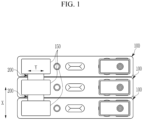
- FIG. 1 A battery module in which a plurality of unit cells 100 are connected through a bus bar 200 according to an exemplary embodiment of the present invention is illustrated in FIG. 1 , and a cross-sectional view along direction X in FIG. 1 of the bus bar 200 which electrically connects one pair of unit cells 100 to each other according to an exemplary embodiment of the present invention is illustrated in FIG. 2 .
- a battery module includes: a plurality of unit cells 100 including a case 120 and an electrode terminal 150 which is protruded from the case 120; and a bus bar 200 which electrically connects any one pair of unit cells 100 among the plurality of unit cells 100.
- the bus bar 200 includes a terminal coupling unit 220 which is inserted between respective electrode terminals 150 of the pair of unit cells 100, and a case coupling unit 240 which is inserted between respective cases 120 of the pair of unit cells 100.
- the unit cell 100 of the present invention may include various types of unit cells, it may preferably include a rechargeable battery which can be charged and discharged.
- the unit cell 100 includes the case 120, and an electrode assembly 110 including an anode, a cathode, and a separator may be accommodated within the case 120.
- the electrode assembly 110 may be formed in a wound shape, a stacked shape, or the like, and the case 120 may be formed in various shapes as necessary.
- the case 120 may have an open shape formed in one surface thereof to accommodate the electrode assembly 110, and a cap plate may be coupled to the open surface of the case 120.
- the unit cell 100 includes electrode terminals 150 which are protruded from the case 120, and the electrode terminals 150 may be installed at various positions including the cap plate and the like as necessary.
- One pair of electrode terminals 150 may be provided for each of the unit cells 100, and the one pair of electrode terminals 150 may each be electrically connected to a cathode and an anode of the electrode assembly 110.
- the bus bar 200 electrically connects any one pair of unit cells 100 among a plurality of unit cells 100 to each other.
- the one pair of unit cells 100 are disposed to be adjacent to each other, and the bus bar 200 may be formed such that the electrode terminals 150 which are each installed at the one pair of unit cells 100 are electrically connected to each other.
- a plurality of unit cells 100 in a battery module may be arranged along a width direction X of the case 120 as illustrated in FIG. 1
- the plurality of unit cells 100 may be arranged in various directions as necessary.
- FIG. 2 illustrates a cross-section of the one pair of unit cells 100 and a bus bar 200 which is inserted between the one pair of unit cells 100.
- the bus bar 200 includes the terminal coupling unit 220 which is inserted between electrode terminals 150 which are each formed in the one pair of unit cells 100, and includes the case coupling unit 240 which is inserted between cases 120 which are formed in the one pair of unit cells 100.
- the bus bar 200 is physically coupled or electrically connected to the electrode terminals 150 of the unit cells 100, and is formed of a conductive material such that the bus bar 200 electrically connects between the unit cells 100.
- the terminal coupling unit 220 of the bus bar 200 is formed to be inserted between the electrode terminals 150 provided in the unit cells 100 that are different from each other such that the terminal coupling unit 220 is brought into contact with the electrode terminals 150.
- the one adjacent pair of unit cells 100 may have their electrode terminals 150 electrically connected to each other by the terminal coupling unit 220.
- the terminal coupling unit 220 may be formed such that the terminal coupling unit 220 is brought into contact with surfaces of the electrode terminals 150 that face each other. Accordingly, the terminal coupling unit 220 can implement an effective electrical connection state while minimizing its volume without being protruded to the outside of the electrode terminal 150.
- FIGS. 1 to 2 illustrate a bus bar 200 of a form which has a tetragonal cross-section and of which both ends portions along a width direction X of the case 120 are brought into contact with the electrode terminal 150 according to an exemplary embodiment of the present invention.
- the case coupling unit 240 is integrally formed with the terminal coupling unit 220, and is inserted between respective cases 120 of the one pair of adjacent unit cells 100. Both surfaces of the case coupling unit 240 along the width direction X of the case 120 are contacted with and supported by the case 120.
- a unit cell 100 may have the electrode terminal 150 formed on a top surface thereof, and the terminal coupling unit 220 may be formed in a longitudinal direction parallel to the width direction X of the case 120 in a battery module according to an exemplary embodiment of the present invention.
- the case coupling unit 240 may be formed such that it is protruded in a downward direction Z from the terminal coupling unit 220, or may have various shapes. However, the case coupling unit 240 may be formed in a square pillar shape having a square or rectangular cross-section as illustrated in FIG. 2 .
- the bus bar 200 may be structurally stably arranged between one pair of unit cells 100 by the case coupling unit 240.
- the case coupling unit 240 has an internal space 205 formed therein, or may be formed to have elasticity such that the case coupling unit 240 absorbs an impact or the like transmitted from the outside of the battery module.
- the case coupling unit 240 is formed to absorb a thickness change according to swelling occurring in the respective unit cells 100.
- the case 120 may be electrically connected to a cathode or an anode of the electrode assembly 110.
- the case coupling unit 240 and the terminal coupling unit 220 are formed of a conductive material, and may be provided to electrically connect the adjacent unit cells 100 in a state that the case coupling unit 240 and the terminal coupling unit 220 are brought into contact with each case 120 of adjacent unit cells 100. Accordingly, the case coupling unit 240 together with the terminal coupling unit 220 can increase an electrical connection area.
- the bus bar 200 including the terminal coupling unit 220 and a case coupling unit 240 is inserted between adjacent unit cells 100 such that the bus bar 200 is brought into contact with and electrically connected to the adjacent unit cells 100. Therefore, an additional coupling member is not required in coupling of the bus bar 200.
- a configuration can be simplified. Furthermore, electrical connectivity can be effectively improved by adding a coupling member such as a bolt or the like, thereby minimizing a resistance increase in the electrical connection of the bus bar 200 and the unit cells 100.
- each of the unit cells in a battery module may include the electrode terminal 150 and the case 120 having the same polarity. That is, the electrode terminal 150 together with the case 120 to which the bus bar 200 is coupled may be electrically connected to any one of a cathode and an anode in the electrode assembly 110.
- the bus bar 200 has a structure in which the terminal coupling unit 220 and the case coupling unit 240 are closely adhered and electrically connected to the electrode terminal 150 and the case 120 of the unit cell 100, the bus bar 200 lowers resistance by effectively increasing an area of the bus bar 200 contacting the unit cell 100, and can effectively improve electrical connection performance thereof.
- the plurality of unit cells 100 in a battery module according to an exemplary embodiment of the present invention are arranged along a width direction X of the case 120, the terminal coupling unit 220 is extended along an arrangement direction of the plurality of unit cells 100, both end portions of the terminal coupling unit 220 are brought into contact with each electrode terminal 150 of the one pair of unit cells 100, the case coupling unit 240 is extended from the terminal coupling unit 220, and both surfaces of the case coupling unit 240 may be brought into contact with each case 120 of the one pair of unit cells 100.
- the terminal coupling unit 220 may be formed in a shape that is extended along an arrangement direction of the unit cells 100 as illustrated in FIG. 2 , i.e., the width direction X of the case 120. Both end portions of the terminal coupling unit 220 along the width direction X of the case 120 are brought into contact with and electrically connected to electrode terminals 150 which face each other.
- the case coupling unit 240 may be preferably extended in a downward direction of the terminal coupling unit 220, and both surfaces of the case coupling unit 240 along the width direction X of the case 120 may be brought into contact with the cases 120 which face each other.
- FIG. 2 illustrates a state in which a bus bar 200 including the terminal coupling unit 220 and the case coupling unit 240 having the above-described shapes is inserted into one pair of unit cells 100.
- the electrode terminal 150 in a battery module according to the present invention has an insertion groove 155 formed in surfaces thereof facing the terminal coupling unit 220 such that the terminal coupling unit 220 is inserted into and coupled to the insertion groove 155, one surface of the insertion groove 155 which is at the side of a longitudinal direction Y of the case 120 is open, and the terminal coupling unit 220 is slid along the longitudinal direction Y of the case 120 such that the terminal coupling unit 220 may be inserted into the insertion groove 155.
- the electrode terminal 150 of the present invention has the insertion groove 155 formed in surfaces thereof which face the terminal coupling unit 220, the insertion groove 155 is formed to be recessed along the width direction X of the case 120, and one surface of the insertion groove 155 along the longitudinal direction Y of the case 120 is open.
- the one open surface of the insertion groove 155 may be one surface of the insertion groove 155 facing the center of the case 120, or the opposite surface thereof, and both surfaces of the insertion groove 155 may be open.
- the bus bar 200 is slid and inserted between one pair of unit cells 100 adjacent along the longitudinal direction Y of the case 120.
- the bus bar 200 may be formed such that the thickness of the bus bar 200 corresponds to that of the insertion groove 155, and both end portions of the bus bar 200 are inserted into and brought into contact with the insertion groove 155 of the electrode terminals 150 which face each other such that both end portions of the bus bar 200 are electrically connected to the insertion groove 155 of the electrode terminals 150.
- the case 120 in a battery module according to an exemplary embodiment of the present invention may have a stepped groove 125 formed in one surface thereof facing the case coupling unit 240 such that the case coupling unit 240 is inserted into the stepped groove 125.
- the case 120 may have the stepped groove 125 formed in one surface thereof facing the case coupling unit 240 of the bus bar 200, the stepped groove 125 is recessed along the width direction X of the case 120, and one surface of the stepped groove 125 along the longitudinal direction Y of the case 120 may be open.
- One surface of the stepped groove 125 is open to be exposed to the outside of the unit cell 100, and the case coupling unit 240 together with the terminal coupling unit 220 may be slid and inserted between respective cases 120 of unit cells 100 adjacent along the longitudinal direction Y of the case 120.
- the insertion groove 155 and the stepped groove 125 have their outer surfaces open along the longitudinal direction Y of the case 120, and the bus bar 200 is slid along the longitudinal direction Y of the case 120 such that the terminal coupling unit 220 is inserted into the insertion groove 155 and the case coupling unit 240 is inserted into and mounted on the stepped groove 125 at the same time.
- the bus bar 200 may be stably inserted between adjacent unit cells 100 and may maintain a stable contact state between the adjacent unit cells 100.
- FIG. 3 is a drawing showing a perspective view of a bus bar 200 in a battery module according to an exemplary embodiment of the present invention.
- the case coupling unit 240 has an internal space 205 formed therein to absorb a separation distance change of the one pair of unit cells 100.
- FIGS. 2 and 3 illustrate a case coupling unit 240 in which the internal space 205 is formed according to the present invention.
- the step coupling unit and the case coupling unit 240 may have a common internal space 205 formed therein as illustrated in FIGS. 2 and 3 .
- the case coupling unit 240 which is inserted to be in surface contact with respective cases 120 of adjacent unit cells 100, has an internal space 205 formed therein to absorb a thickness change or an external impact due to swelling of the unit cells 100.
- a swelling phenomenon of the unit cells 100 may be generated due to various reasons in the operation situation of a battery module. Thickness variation of the unit cells 100 may be generated under the swelling circumstances in which volume of the case 120 is expanded by an increase in internal pressure of the unit cell 100.
- the case coupling unit 240 may have a reduced thickness by forming the internal space 205 in the case coupling unit 240 of a bus bar 200 which is coupled to the unit cell 100 that is expanded by swelling such that the case coupling unit 240 is compressed as much as a thickness increment of the case 120.
- the case coupling unit 240 the present invention has the internal space 205 formed therein such that the case coupling unit 240 is formed to have a varied thickness according to an external pressure, thereby effectively coping with swelling of the unit cell 100, and further providing a buffer space for absorbing an external impact.
- a bus bar 200 of a battery module includes the terminal coupling unit 220 and the case coupling unit 240 which are formed by bending a single conductive member, and both surfaces of the bus bar 200 are open along the longitudinal direction Y of the case 120.
- the bus bar 200 is formed by bending a plate-shaped member made of metal several times. That is, the bus bar 200 is integrally composed of the terminal coupling unit 220 and the case coupling unit 240, and may be formed in the form of a clip by bending a single conductive member several times.
- the bus bar 200 which is formed by bending a single member according to the present invention is formed with a hollow form having the internal space 205 formed therein, and is formed such that both surfaces of the bus bar 200 are open along the longitudinal direction Y of the case 120.
- the bus bar 200 is advantageous for allowing a thickness variation thereof and enabling it to be elastically compressed and restored when swelling of the unit cell 100 is generated by forming the bus bar 200 by bending the single member such that the internal space 205 is formed therein. Moreover, since the bus bar 200 has a shape of which both surfaces thereof are opened along the longitudinal direction Y of the case 120, compression and restoration of the bus bar 200 according to an external pressure may easily occur.
- the case coupling unit 240 in a battery module according to an exemplary embodiment of the present invention is extended from the terminal coupling unit 220, and an end portion 245 of the case coupling unit 240 may be opened such that the internal space 205 is exposed to the outside.
- the bus bar 200 illustrated in FIGS. 2 and 3 is formed by protruding the case coupling unit 240 in a downward direction of the terminal coupling unit 220, and the end portion 245 of the case coupling unit 240 has an opened shape.
- the case coupling unit 240 of which the internal space 205 is exposed from the opened end portion 245 to the outside has a free end formed in lower end portions of both surfaces thereof that are brought into contact with the case 120.
- the case coupling unit 240 which is compressed in the width direction X of the case 120 according to generation of swelling or the like of the unit cell 100 facilitates displacement due to compression by forming the free end in the lower end portions of both surfaces of the case coupling unit 240. Accordingly, a thickness variation of the unit cell 100 due to swelling or the like effectively occurs.
- an insulating member 250 having elasticity may be provided in the internal space 205 of the case coupling unit 240 in the bus bar 200 illustrated in FIGS. 2 and 3 .
- the insulating member 250 may be formed of materials such as rubber or urethane which have high elastic modulus.
- the case coupling unit 240 according to an exemplary embodiment of the present invention has the insulating member 250 having elasticity formed therein. Therefore, the case coupling unit 240 can maintain a state in which both surfaces of the case coupling unit 240 are stably closely adhered to the case 120 of the unit cell 100 by elasticity of the insulating member 250 even when the case coupling unit 240 returns to the normal state after a separation distance between the unit cells 100 is reduced according to the generation of swelling.
- the insulating member 250 may be formed of various materials, and the insulating member 250 may be provided such that the insulating member 250 is closely adhered to and supported by an inner surface of the case coupling unit 240 in the internal space 205 of the case coupling unit 240.
- the shape of the insulating member 250 may include a shape which is formed by the internal space 205 of the case coupling unit 240 or shapes that are diversely determined as needed.
Landscapes
- Chemical & Material Sciences (AREA)
- Chemical Kinetics & Catalysis (AREA)
- Electrochemistry (AREA)
- General Chemical & Material Sciences (AREA)
- Connection Of Batteries Or Terminals (AREA)
- Battery Mounting, Suspending (AREA)
Applications Claiming Priority (1)
| Application Number | Priority Date | Filing Date | Title |
|---|---|---|---|
| KR1020180067516A KR102598260B1 (ko) | 2018-06-12 | 2018-06-12 | 전지모듈 |
Publications (2)
| Publication Number | Publication Date |
|---|---|
| EP3582292A1 EP3582292A1 (en) | 2019-12-18 |
| EP3582292B1 true EP3582292B1 (en) | 2023-08-02 |
Family
ID=66668816
Family Applications (1)
| Application Number | Title | Priority Date | Filing Date |
|---|---|---|---|
| EP19176973.6A Active EP3582292B1 (en) | 2018-06-12 | 2019-05-28 | Battery module |
Country Status (6)
| Country | Link |
|---|---|
| US (1) | US11196127B2 (pl) |
| EP (1) | EP3582292B1 (pl) |
| KR (1) | KR102598260B1 (pl) |
| CN (1) | CN110600665B (pl) |
| HU (1) | HUE063453T2 (pl) |
| PL (1) | PL3582292T3 (pl) |
Families Citing this family (3)
| Publication number | Priority date | Publication date | Assignee | Title |
|---|---|---|---|---|
| CN112038521B (zh) * | 2020-08-18 | 2024-10-29 | 嘉兴模度新能源有限公司 | 一种电池同向排列并成排串联的电池模块 |
| KR102758793B1 (ko) * | 2022-06-16 | 2025-01-21 | 주식회사 엘지에너지솔루션 | 단자 구조가 개선된 이차전지 |
| JP2025108124A (ja) * | 2024-01-10 | 2025-07-23 | 矢崎総業株式会社 | 接続構造および組立体 |
Family Cites Families (13)
| Publication number | Priority date | Publication date | Assignee | Title |
|---|---|---|---|---|
| JP4154136B2 (ja) * | 2001-08-06 | 2008-09-24 | 松下電器産業株式会社 | 角形密閉式電池 |
| KR100560483B1 (ko) | 2004-05-04 | 2006-03-13 | 삼성에스디아이 주식회사 | 이차 전지 |
| KR100648720B1 (ko) * | 2004-12-02 | 2006-11-23 | 삼성에스디아이 주식회사 | 이차 전지의 케이스와, 이를 이용한 이차 전지 및 이차전지 모듈 |
| KR200421590Y1 (ko) * | 2006-04-11 | 2006-07-13 | 송재중 | 인쇄회로기판 삽입방식의 직류전압변환장치 |
| FR2979472B1 (fr) | 2011-08-29 | 2013-08-23 | Batscap Sa | Connecteur dispose entre deux ensembles de stockage d'energie |
| US20130260611A1 (en) | 2012-04-03 | 2013-10-03 | Jang-Gun Ahn | Battery module |
| KR20150069733A (ko) | 2013-12-16 | 2015-06-24 | 삼성에스디아이 주식회사 | 배터리 모듈 |
| KR102221801B1 (ko) * | 2014-02-04 | 2021-03-02 | 삼성에스디아이 주식회사 | 버스바 모듈 |
| KR102037101B1 (ko) | 2015-05-08 | 2019-10-28 | 비와이디 컴퍼니 리미티드 | 배터리 셀 커넥터 |
| KR102341402B1 (ko) | 2015-05-15 | 2021-12-20 | 삼성에스디아이 주식회사 | 배터리 모듈 |
| KR102449864B1 (ko) | 2015-09-04 | 2022-09-30 | 현대모비스 주식회사 | 전지모듈 어셈블리용 접속장치 |
| DE102016200961A1 (de) * | 2016-01-25 | 2017-07-27 | Bayerische Motoren Werke Aktiengesellschaft | Verbindersystem, Batteriemodul, Verfahren zum Ausbilden eines Abgriffes und Betriebsvorrichtung |
| CN107170943A (zh) | 2017-07-05 | 2017-09-15 | 江西优特汽车技术有限公司 | 隔板及具有其的软包动力电池 |
-
2018
- 2018-06-12 KR KR1020180067516A patent/KR102598260B1/ko active Active
-
2019
- 2019-05-20 US US16/416,643 patent/US11196127B2/en active Active
- 2019-05-21 CN CN201910423085.7A patent/CN110600665B/zh active Active
- 2019-05-28 EP EP19176973.6A patent/EP3582292B1/en active Active
- 2019-05-28 HU HUE19176973A patent/HUE063453T2/hu unknown
- 2019-05-28 PL PL19176973.6T patent/PL3582292T3/pl unknown
Also Published As
| Publication number | Publication date |
|---|---|
| KR20190140696A (ko) | 2019-12-20 |
| PL3582292T3 (pl) | 2024-01-15 |
| US20190379023A1 (en) | 2019-12-12 |
| HUE063453T2 (hu) | 2024-01-28 |
| KR102598260B1 (ko) | 2023-11-02 |
| CN110600665A (zh) | 2019-12-20 |
| CN110600665B (zh) | 2022-12-23 |
| US11196127B2 (en) | 2021-12-07 |
| EP3582292A1 (en) | 2019-12-18 |
Similar Documents
| Publication | Publication Date | Title |
|---|---|---|
| US9203065B2 (en) | Battery module | |
| CN104183809B (zh) | 电池模块 | |
| CN107851759B (zh) | 电池模块及包括该电池模块的电池组和车辆 | |
| US9748539B2 (en) | Battery module | |
| US9178206B2 (en) | Battery module | |
| CN103000835B (zh) | 电池模块 | |
| US8338021B2 (en) | Battery module | |
| EP3512003B1 (en) | Component for collecting current and battery | |
| JP5319165B2 (ja) | 電池パック及び電池ケース | |
| US8592079B2 (en) | Rechargeable battery | |
| US7993774B2 (en) | Conductive plate and secondary battery pack using conductive plate | |
| US20150079452A1 (en) | Battery module | |
| EP3651236A1 (en) | Battery module and battery pack comprising same | |
| EP3582292B1 (en) | Battery module | |
| US8871375B2 (en) | Coupling member between battery cells and battery cell assembly using the same | |
| US20140308569A1 (en) | Battery pack | |
| US9997809B2 (en) | Battery module | |
| EP4080664A2 (en) | Battery module having flexible busbar | |
| JP7176816B2 (ja) | バッテリーモジュール | |
| EP4518005A1 (en) | Terminal structure assembly integrally including busbar | |
| CN121488359A (zh) | 电池组 |
Legal Events
| Date | Code | Title | Description |
|---|---|---|---|
| PUAI | Public reference made under article 153(3) epc to a published international application that has entered the european phase |
Free format text: ORIGINAL CODE: 0009012 |
|
| STAA | Information on the status of an ep patent application or granted ep patent |
Free format text: STATUS: REQUEST FOR EXAMINATION WAS MADE |
|
| 17P | Request for examination filed |
Effective date: 20190528 |
|
| AK | Designated contracting states |
Kind code of ref document: A1 Designated state(s): AL AT BE BG CH CY CZ DE DK EE ES FI FR GB GR HR HU IE IS IT LI LT LU LV MC MK MT NL NO PL PT RO RS SE SI SK SM TR |
|
| AX | Request for extension of the european patent |
Extension state: BA ME |
|
| STAA | Information on the status of an ep patent application or granted ep patent |
Free format text: STATUS: EXAMINATION IS IN PROGRESS |
|
| 17Q | First examination report despatched |
Effective date: 20200909 |
|
| REG | Reference to a national code |
Ref legal event code: R079 Ipc: H01M0050503000 Ref country code: DE Ref legal event code: R079 Ref document number: 602019033875 Country of ref document: DE Free format text: PREVIOUS MAIN CLASS: H01M0002200000 Ipc: H01M0050503000 |
|
| GRAP | Despatch of communication of intention to grant a patent |
Free format text: ORIGINAL CODE: EPIDOSNIGR1 |
|
| STAA | Information on the status of an ep patent application or granted ep patent |
Free format text: STATUS: GRANT OF PATENT IS INTENDED |
|
| RIC1 | Information provided on ipc code assigned before grant |
Ipc: H01M 50/209 20210101ALI20230210BHEP Ipc: H01M 50/502 20210101ALI20230210BHEP Ipc: H01M 50/503 20210101AFI20230210BHEP |
|
| INTG | Intention to grant announced |
Effective date: 20230310 |
|
| GRAS | Grant fee paid |
Free format text: ORIGINAL CODE: EPIDOSNIGR3 |
|
| GRAA | (expected) grant |
Free format text: ORIGINAL CODE: 0009210 |
|
| STAA | Information on the status of an ep patent application or granted ep patent |
Free format text: STATUS: THE PATENT HAS BEEN GRANTED |
|
| AK | Designated contracting states |
Kind code of ref document: B1 Designated state(s): AL AT BE BG CH CY CZ DE DK EE ES FI FR GB GR HR HU IE IS IT LI LT LU LV MC MK MT NL NO PL PT RO RS SE SI SK SM TR |
|
| REG | Reference to a national code |
Ref country code: GB Ref legal event code: FG4D |
|
| REG | Reference to a national code |
Ref country code: CH Ref legal event code: EP |
|
| REG | Reference to a national code |
Ref country code: DE Ref legal event code: R096 Ref document number: 602019033875 Country of ref document: DE |
|
| REG | Reference to a national code |
Ref country code: IE Ref legal event code: FG4D |
|
| REG | Reference to a national code |
Ref country code: SE Ref legal event code: TRGR |
|
| REG | Reference to a national code |
Ref country code: LT Ref legal event code: MG9D |
|
| REG | Reference to a national code |
Ref country code: NL Ref legal event code: MP Effective date: 20230802 |
|
| REG | Reference to a national code |
Ref country code: AT Ref legal event code: MK05 Ref document number: 1595857 Country of ref document: AT Kind code of ref document: T Effective date: 20230802 |
|
| PG25 | Lapsed in a contracting state [announced via postgrant information from national office to epo] |
Ref country code: GR Free format text: LAPSE BECAUSE OF FAILURE TO SUBMIT A TRANSLATION OF THE DESCRIPTION OR TO PAY THE FEE WITHIN THE PRESCRIBED TIME-LIMIT Effective date: 20231103 |
|
| PG25 | Lapsed in a contracting state [announced via postgrant information from national office to epo] |
Ref country code: IS Free format text: LAPSE BECAUSE OF FAILURE TO SUBMIT A TRANSLATION OF THE DESCRIPTION OR TO PAY THE FEE WITHIN THE PRESCRIBED TIME-LIMIT Effective date: 20231202 |
|
| REG | Reference to a national code |
Ref country code: HU Ref legal event code: AG4A Ref document number: E063453 Country of ref document: HU |
|
| PG25 | Lapsed in a contracting state [announced via postgrant information from national office to epo] |
Ref country code: RS Free format text: LAPSE BECAUSE OF FAILURE TO SUBMIT A TRANSLATION OF THE DESCRIPTION OR TO PAY THE FEE WITHIN THE PRESCRIBED TIME-LIMIT Effective date: 20230802 Ref country code: PT Free format text: LAPSE BECAUSE OF FAILURE TO SUBMIT A TRANSLATION OF THE DESCRIPTION OR TO PAY THE FEE WITHIN THE PRESCRIBED TIME-LIMIT Effective date: 20231204 Ref country code: NO Free format text: LAPSE BECAUSE OF FAILURE TO SUBMIT A TRANSLATION OF THE DESCRIPTION OR TO PAY THE FEE WITHIN THE PRESCRIBED TIME-LIMIT Effective date: 20231102 Ref country code: NL Free format text: LAPSE BECAUSE OF FAILURE TO SUBMIT A TRANSLATION OF THE DESCRIPTION OR TO PAY THE FEE WITHIN THE PRESCRIBED TIME-LIMIT Effective date: 20230802 Ref country code: LV Free format text: LAPSE BECAUSE OF FAILURE TO SUBMIT A TRANSLATION OF THE DESCRIPTION OR TO PAY THE FEE WITHIN THE PRESCRIBED TIME-LIMIT Effective date: 20230802 Ref country code: LT Free format text: LAPSE BECAUSE OF FAILURE TO SUBMIT A TRANSLATION OF THE DESCRIPTION OR TO PAY THE FEE WITHIN THE PRESCRIBED TIME-LIMIT Effective date: 20230802 Ref country code: IS Free format text: LAPSE BECAUSE OF FAILURE TO SUBMIT A TRANSLATION OF THE DESCRIPTION OR TO PAY THE FEE WITHIN THE PRESCRIBED TIME-LIMIT Effective date: 20231202 Ref country code: HR Free format text: LAPSE BECAUSE OF FAILURE TO SUBMIT A TRANSLATION OF THE DESCRIPTION OR TO PAY THE FEE WITHIN THE PRESCRIBED TIME-LIMIT Effective date: 20230802 Ref country code: GR Free format text: LAPSE BECAUSE OF FAILURE TO SUBMIT A TRANSLATION OF THE DESCRIPTION OR TO PAY THE FEE WITHIN THE PRESCRIBED TIME-LIMIT Effective date: 20231103 Ref country code: FI Free format text: LAPSE BECAUSE OF FAILURE TO SUBMIT A TRANSLATION OF THE DESCRIPTION OR TO PAY THE FEE WITHIN THE PRESCRIBED TIME-LIMIT Effective date: 20230802 Ref country code: AT Free format text: LAPSE BECAUSE OF FAILURE TO SUBMIT A TRANSLATION OF THE DESCRIPTION OR TO PAY THE FEE WITHIN THE PRESCRIBED TIME-LIMIT Effective date: 20230802 |
|
| PG25 | Lapsed in a contracting state [announced via postgrant information from national office to epo] |
Ref country code: ES Free format text: LAPSE BECAUSE OF FAILURE TO SUBMIT A TRANSLATION OF THE DESCRIPTION OR TO PAY THE FEE WITHIN THE PRESCRIBED TIME-LIMIT Effective date: 20230802 |
|
| PG25 | Lapsed in a contracting state [announced via postgrant information from national office to epo] |
Ref country code: SM Free format text: LAPSE BECAUSE OF FAILURE TO SUBMIT A TRANSLATION OF THE DESCRIPTION OR TO PAY THE FEE WITHIN THE PRESCRIBED TIME-LIMIT Effective date: 20230802 Ref country code: RO Free format text: LAPSE BECAUSE OF FAILURE TO SUBMIT A TRANSLATION OF THE DESCRIPTION OR TO PAY THE FEE WITHIN THE PRESCRIBED TIME-LIMIT Effective date: 20230802 Ref country code: ES Free format text: LAPSE BECAUSE OF FAILURE TO SUBMIT A TRANSLATION OF THE DESCRIPTION OR TO PAY THE FEE WITHIN THE PRESCRIBED TIME-LIMIT Effective date: 20230802 Ref country code: EE Free format text: LAPSE BECAUSE OF FAILURE TO SUBMIT A TRANSLATION OF THE DESCRIPTION OR TO PAY THE FEE WITHIN THE PRESCRIBED TIME-LIMIT Effective date: 20230802 Ref country code: DK Free format text: LAPSE BECAUSE OF FAILURE TO SUBMIT A TRANSLATION OF THE DESCRIPTION OR TO PAY THE FEE WITHIN THE PRESCRIBED TIME-LIMIT Effective date: 20230802 Ref country code: CZ Free format text: LAPSE BECAUSE OF FAILURE TO SUBMIT A TRANSLATION OF THE DESCRIPTION OR TO PAY THE FEE WITHIN THE PRESCRIBED TIME-LIMIT Effective date: 20230802 Ref country code: SK Free format text: LAPSE BECAUSE OF FAILURE TO SUBMIT A TRANSLATION OF THE DESCRIPTION OR TO PAY THE FEE WITHIN THE PRESCRIBED TIME-LIMIT Effective date: 20230802 |
|
| REG | Reference to a national code |
Ref country code: DE Ref legal event code: R097 Ref document number: 602019033875 Country of ref document: DE |
|
| PG25 | Lapsed in a contracting state [announced via postgrant information from national office to epo] |
Ref country code: IT Free format text: LAPSE BECAUSE OF FAILURE TO SUBMIT A TRANSLATION OF THE DESCRIPTION OR TO PAY THE FEE WITHIN THE PRESCRIBED TIME-LIMIT Effective date: 20230802 |
|
| PLBE | No opposition filed within time limit |
Free format text: ORIGINAL CODE: 0009261 |
|
| STAA | Information on the status of an ep patent application or granted ep patent |
Free format text: STATUS: NO OPPOSITION FILED WITHIN TIME LIMIT |
|
| 26N | No opposition filed |
Effective date: 20240503 |
|
| PG25 | Lapsed in a contracting state [announced via postgrant information from national office to epo] |
Ref country code: SI Free format text: LAPSE BECAUSE OF FAILURE TO SUBMIT A TRANSLATION OF THE DESCRIPTION OR TO PAY THE FEE WITHIN THE PRESCRIBED TIME-LIMIT Effective date: 20230802 |
|
| PG25 | Lapsed in a contracting state [announced via postgrant information from national office to epo] |
Ref country code: BG Free format text: LAPSE BECAUSE OF FAILURE TO SUBMIT A TRANSLATION OF THE DESCRIPTION OR TO PAY THE FEE WITHIN THE PRESCRIBED TIME-LIMIT Effective date: 20230802 |
|
| PG25 | Lapsed in a contracting state [announced via postgrant information from national office to epo] |
Ref country code: BG Free format text: LAPSE BECAUSE OF FAILURE TO SUBMIT A TRANSLATION OF THE DESCRIPTION OR TO PAY THE FEE WITHIN THE PRESCRIBED TIME-LIMIT Effective date: 20230802 |
|
| REG | Reference to a national code |
Ref country code: CH Ref legal event code: PL |
|
| PG25 | Lapsed in a contracting state [announced via postgrant information from national office to epo] |
Ref country code: MC Free format text: LAPSE BECAUSE OF FAILURE TO SUBMIT A TRANSLATION OF THE DESCRIPTION OR TO PAY THE FEE WITHIN THE PRESCRIBED TIME-LIMIT Effective date: 20230802 |
|
| PG25 | Lapsed in a contracting state [announced via postgrant information from national office to epo] |
Ref country code: LU Free format text: LAPSE BECAUSE OF NON-PAYMENT OF DUE FEES Effective date: 20240528 |
|
| PG25 | Lapsed in a contracting state [announced via postgrant information from national office to epo] |
Ref country code: MC Free format text: LAPSE BECAUSE OF FAILURE TO SUBMIT A TRANSLATION OF THE DESCRIPTION OR TO PAY THE FEE WITHIN THE PRESCRIBED TIME-LIMIT Effective date: 20230802 Ref country code: LU Free format text: LAPSE BECAUSE OF NON-PAYMENT OF DUE FEES Effective date: 20240528 Ref country code: CH Free format text: LAPSE BECAUSE OF NON-PAYMENT OF DUE FEES Effective date: 20240531 |
|
| REG | Reference to a national code |
Ref country code: BE Ref legal event code: MM Effective date: 20240531 |
|
| PG25 | Lapsed in a contracting state [announced via postgrant information from national office to epo] |
Ref country code: IE Free format text: LAPSE BECAUSE OF NON-PAYMENT OF DUE FEES Effective date: 20240528 |
|
| PG25 | Lapsed in a contracting state [announced via postgrant information from national office to epo] |
Ref country code: BE Free format text: LAPSE BECAUSE OF NON-PAYMENT OF DUE FEES Effective date: 20240531 |
|
| PGFP | Annual fee paid to national office [announced via postgrant information from national office to epo] |
Ref country code: PL Payment date: 20250505 Year of fee payment: 7 Ref country code: DE Payment date: 20250429 Year of fee payment: 7 |
|
| PGFP | Annual fee paid to national office [announced via postgrant information from national office to epo] |
Ref country code: GB Payment date: 20250501 Year of fee payment: 7 |
|
| PGFP | Annual fee paid to national office [announced via postgrant information from national office to epo] |
Ref country code: HU Payment date: 20250529 Year of fee payment: 7 |
|
| PGFP | Annual fee paid to national office [announced via postgrant information from national office to epo] |
Ref country code: FR Payment date: 20250508 Year of fee payment: 7 |
|
| PGFP | Annual fee paid to national office [announced via postgrant information from national office to epo] |
Ref country code: SE Payment date: 20250429 Year of fee payment: 7 |
|
| PG25 | Lapsed in a contracting state [announced via postgrant information from national office to epo] |
Ref country code: CY Free format text: LAPSE BECAUSE OF FAILURE TO SUBMIT A TRANSLATION OF THE DESCRIPTION OR TO PAY THE FEE WITHIN THE PRESCRIBED TIME-LIMIT; INVALID AB INITIO Effective date: 20190528 |