EP3581532A1 - Spun yarn winding apparatus - Google Patents
Spun yarn winding apparatus Download PDFInfo
- Publication number
- EP3581532A1 EP3581532A1 EP19173271.8A EP19173271A EP3581532A1 EP 3581532 A1 EP3581532 A1 EP 3581532A1 EP 19173271 A EP19173271 A EP 19173271A EP 3581532 A1 EP3581532 A1 EP 3581532A1
- Authority
- EP
- European Patent Office
- Prior art keywords
- bobbin
- axial direction
- guides
- bobbins
- guide
- Prior art date
- Legal status (The legal status is an assumption and is not a legal conclusion. Google has not performed a legal analysis and makes no representation as to the accuracy of the status listed.)
- Granted
Links
Images





Classifications
-
- B—PERFORMING OPERATIONS; TRANSPORTING
- B65—CONVEYING; PACKING; STORING; HANDLING THIN OR FILAMENTARY MATERIAL
- B65H—HANDLING THIN OR FILAMENTARY MATERIAL, e.g. SHEETS, WEBS, CABLES
- B65H54/00—Winding, coiling, or depositing filamentary material
- B65H54/02—Winding and traversing material on to reels, bobbins, tubes, or like package cores or formers
- B65H54/28—Traversing devices; Package-shaping arrangements
- B65H54/2881—Traversing devices with a plurality of guides for winding on a plurality of bobbins
-
- B—PERFORMING OPERATIONS; TRANSPORTING
- B65—CONVEYING; PACKING; STORING; HANDLING THIN OR FILAMENTARY MATERIAL
- B65H—HANDLING THIN OR FILAMENTARY MATERIAL, e.g. SHEETS, WEBS, CABLES
- B65H54/00—Winding, coiling, or depositing filamentary material
- B65H54/02—Winding and traversing material on to reels, bobbins, tubes, or like package cores or formers
- B65H54/28—Traversing devices; Package-shaping arrangements
- B65H54/34—Traversing devices; Package-shaping arrangements for laying subsidiary winding, e.g. transfer tails
- B65H54/343—Traversing devices; Package-shaping arrangements for laying subsidiary winding, e.g. transfer tails when starting winding on an empty bobbin
-
- B—PERFORMING OPERATIONS; TRANSPORTING
- B65—CONVEYING; PACKING; STORING; HANDLING THIN OR FILAMENTARY MATERIAL
- B65H—HANDLING THIN OR FILAMENTARY MATERIAL, e.g. SHEETS, WEBS, CABLES
- B65H65/00—Securing material to cores or formers
-
- B—PERFORMING OPERATIONS; TRANSPORTING
- B65—CONVEYING; PACKING; STORING; HANDLING THIN OR FILAMENTARY MATERIAL
- B65H—HANDLING THIN OR FILAMENTARY MATERIAL, e.g. SHEETS, WEBS, CABLES
- B65H67/00—Replacing or removing cores, receptacles, or completed packages at paying-out, winding, or depositing stations
- B65H67/04—Arrangements for removing completed take-up packages and or replacing by cores, formers, or empty receptacles at winding or depositing stations; Transferring material between adjacent full and empty take-up elements
- B65H67/0405—Arrangements for removing completed take-up packages or for loading an empty core
- B65H67/0417—Arrangements for removing completed take-up packages or for loading an empty core for loading an empty core
- B65H67/0422—Arrangements for removing completed take-up packages or for loading an empty core for loading an empty core for loading a starter winding, i.e. a spool core with a small length of yarn wound on it; preparing the starter winding
-
- B—PERFORMING OPERATIONS; TRANSPORTING
- B65—CONVEYING; PACKING; STORING; HANDLING THIN OR FILAMENTARY MATERIAL
- B65H—HANDLING THIN OR FILAMENTARY MATERIAL, e.g. SHEETS, WEBS, CABLES
- B65H67/00—Replacing or removing cores, receptacles, or completed packages at paying-out, winding, or depositing stations
- B65H67/04—Arrangements for removing completed take-up packages and or replacing by cores, formers, or empty receptacles at winding or depositing stations; Transferring material between adjacent full and empty take-up elements
- B65H67/044—Continuous winding apparatus for winding on two or more winding heads in succession
- B65H67/048—Continuous winding apparatus for winding on two or more winding heads in succession having winding heads arranged on rotary capstan head
-
- D—TEXTILES; PAPER
- D01—NATURAL OR MAN-MADE THREADS OR FIBRES; SPINNING
- D01D—MECHANICAL METHODS OR APPARATUS IN THE MANUFACTURE OF ARTIFICIAL FILAMENTS, THREADS, FIBRES, BRISTLES OR RIBBONS
- D01D13/00—Complete machines for producing artificial threads
- D01D13/02—Elements of machines in combination
-
- D—TEXTILES; PAPER
- D01—NATURAL OR MAN-MADE THREADS OR FIBRES; SPINNING
- D01D—MECHANICAL METHODS OR APPARATUS IN THE MANUFACTURE OF ARTIFICIAL FILAMENTS, THREADS, FIBRES, BRISTLES OR RIBBONS
- D01D7/00—Collecting the newly-spun products
-
- B—PERFORMING OPERATIONS; TRANSPORTING
- B65—CONVEYING; PACKING; STORING; HANDLING THIN OR FILAMENTARY MATERIAL
- B65H—HANDLING THIN OR FILAMENTARY MATERIAL, e.g. SHEETS, WEBS, CABLES
- B65H2701/00—Handled material; Storage means
- B65H2701/30—Handled filamentary material
- B65H2701/31—Textiles threads or artificial strands of filaments
Definitions
- the present invention relates to a spun yarn winding apparatus including bobbin holders.
- the spun yarn winding apparatus includes a yarn threading mechanism which threads yarns into slits formed on the outer circumferential surfaces of new bobbins, when bobbins on which yarns are wound are switched from bobbins retained by one bobbin holder to new bobbins retained by another bobbin holder.
- Patent Literature 1 Japanese Laid-Open Patent Publication No. 2017-154891 .
- a yarn traversed by a traverse unit is captured by a yarn capturing guide (hereinafter, guide), and the yarn is threaded to the new bobbin.
- guide a yarn capturing guide
- a slit into which a yarn is threaded is typically formed on the outer circumferential surface of a bobbin. Yarn threading is performed in such a way that a yarn captured by the guide is guided to the slit of the new bobbin.
- the guide is arranged to be movable in the axial direction of the bobbin by a cylinder.
- the guide When the yarn is being wound, the guide is on standby at a yarn shifting position which is out of a traversal range, and moves to a capturing position where the yarn can be captured, at the time of the switching to a new bobbin.
- the yarn shifting position As the guide having captured the yarn returns to the yarn shifting position, the yarn is threaded into the slit of the new bobbin.
- the above-described guide is controlled with the assumption that the length of the bobbin is identical with a predetermined standard size.
- the length of the bobbin has a dimensional error from the predetermined standard size, there is a difference between relative positions of the guide and the bobbin in the axial direction, with the result that the yarn cannot be threaded into the slit.
- This problem is particularly conspicuous when many bobbins are attached to one bobbin holder. This is because bobbins of the same lot are typically used simultaneously, and dimensional errors of bobbins attached to one bobbin holder are often substantially identical with each other. The dimensional errors are therefore accumulated when the bobbins are lined up in the axial direction, and a failure in yarn threading is likely to occur in such a case.
- an object of a spun yarn winding apparatus of the present invention is to successfully thread a yarn into a slit when a bobbin to which the yarn is wound is switched to a new bobbin, even if the length of the bobbin has a dimensional error from a predetermined standard size.
- the present invention relates to a spun yarn winding apparatus configured to wind yarns spun out from a spinning apparatus onto bobbins, which includes: bobbin holders by which the bobbins are retained to be lined up in an axial direction; a traverse unit which is configured to traverse the yarns; a yarn threading mechanism which is configured to thread the yarns into slits formed in outer circumferential surfaces of new bobbins, when bobbins on which yarns are wound are switched from bobbins retained by one of the bobbin holders to the new bobbins retained by another one of the bobbin holders; and a controller, the yarn threading mechanism including: guides which are provided to correspond to the respective new bobbins and are movable in the axial direction, the guides moving toward the corresponding slits after capturing the yarns traversed by the traverse unit and then threading the yarns into the slits; a driving unit configured to move the guides in the axial direction; and a bobbin position sensor configured to detect a
- the position in the axial direction of the guide is adjusted.
- the positional deviation is restrained by performing the position adjustment of the guide.
- the spun yarn winding apparatus of the present invention may be arranged such that, when the guides having captured the yarns are moved toward the corresponding slits, the controller performs adjustment in such a manner that the guides stop at the same positions as the corresponding slits in the axial direction or at predetermined positions over the corresponding slits.
- the spun yarn winding apparatus of the present invention may be arranged such that the bobbins are attached and detached from one end side of each of the bobbin holders in the axial direction, and the bobbin position sensor detects a position of an end face on the one end side of a bobbin which is closest to the one end of the corresponding bobbin holder among the new bobbins.
- the bobbin attached first is closest to the other end whereas the bobbin attached last is closest to the one end.
- the dimensional errors are accumulated toward the one end side and the positional deviation is most significant at the bobbin closest to the one end. It is therefore possible to accurately grasp the deviations in relative position between the guides and the bobbins by detecting the position of the end face on the one end side of the bobbin which is closest to the one end.
- the spun yarn winding apparatus of the present invention may be arranged such that the bobbin position sensor detects the position of the end face when the new bobbins do not rotate.
- the detection of the position of the end face may not be successfully done when the bobbin rotates and vibrates. On this account, the position of the end face is certainly detected when the position of the end face is detected when the bobbin does not rotate.
- the spun yarn winding apparatus of the present invention may be arranged such that the bobbin position sensor detects the position of the end face when the new bobbins are rotating.
- a detection error in the position of the bobbin is significant if the detection is performed at a distinctively irregular part.
- the influence of the distinctive irregularity is restrained by detecting the position of the end face while the bobbin is rotating.
- the spun yarn winding apparatus of the present invention may be arranged such that each of the bobbin holders is movable at least between a winding start position where winding of the yarns onto the new bobbins starts and a replacement position where the bobbins are replaced, and the bobbin position sensor detects the position of the end face when the another one of the bobbin holders is at the winding start position.
- the bobbin position sensor is provided in the vicinity of the winding start position, and is therefore far from the replacement position. In this way, it is possible to easily provide the bobbin position sensor not to obstruct the replacement of the bobbins.
- the spun yarn winding apparatus of the present invention may be arranged such that an alarm is provided to notify an operator of a predetermined state, and the controller activates the alarm when it is determined based on a detection result of the bobbin position sensor that the length of each of the new bobbins does not fall within a predetermined dimensional tolerance range.
- This arrangement allows the operator to promptly know that the length of the new bobbin does not fall within the dimensional tolerance range, and this problem is suitably dealt with.
- the spun yarn winding apparatus of the present invention may be arranged such that the controller terminates winding of the yarns when it is determined based on a detection result of the bobbin position sensor that each of the yarns cannot be wound within a predetermined winding allowable range on each of the new bobbins.
- This arrangement prevents the formation of a defective package in which the yarn is not wound within the winding allowable range.
- the spun yarn winding apparatus of the present invention may be arranged such that the controller accumulates detection results of the bobbin position sensor and performs quality control of the bobbins based on accumulated data.
- the spun yarn winding apparatus of the present invention may be arranged such that the driving unit includes: a supporting member which supports the guides; and a mover which is configured to move the guides together in the axial direction by moving the supporting member in the axial direction.
- This arrangement simplifies the device configuration as compared to cases where each guide is individually moved.
- the spun yarn winding apparatus of the present invention may be arranged such that the driving unit includes a pitch changing mechanism which is configured to change intervals in the axial direction of the guides.
- Such a pitch changing mechanism allows the position of each guide to coincide with the position of the slit, with the result that the success rate of the yarn threading is improved.
- the spun yarn winding apparatus of the present invention may be arranged such that the pitch changing mechanism includes: a screw which is the supporting member, male screw parts being formed on the screw to correspond to the respective guides and to be lined up in the axial direction; nuts which are screwed to the respective male screw parts, the guides being attached to the respective nuts; and a rotary device configured to move the nuts in the axial direction relative to the screw by rotating the screw about an axis of the screw, the male screw parts are arranged so that, when leads of two neighboring male screw parts are compared with each other, the lead of one screw part on one end side in the axial direction is longer than or shorter than the lead of the other screw part.
- This arrangement makes it possible to arrange the position of each guide to coincide with the position of the slit by rotating the screw.
- the spun yarn winding apparatus of the present invention may be arranged such that the pitch changing mechanism includes: a pantograph mechanism extendable and contractible in the axial direction; a telescopic device provided to extend and shorten the pantograph mechanism; and a base member which is the supporting member and on which the pantograph mechanism and the telescopic device are mounted, the guides being attached to the pantograph mechanism to be lined up in the axial direction.
- This arrangement makes it possible to arrange the position of each guide to coincide with the position of the slit by adjusting the extension amount of the pantograph mechanism.
- the spun yarn winding apparatus of the present invention may be arranged such that the driving unit is arranged to allow at least one of the guides to be movable in the axial direction relative to the supporting member.
- the degree of freedom in position adjustment of each guide is improved as compared to cases where the positions of all guides are only adjustable together by the movement of the supporting member.
- the spun yarn winding apparatus of the present invention may be arranged such that the driving unit includes: a screw which is the supporting member, a male screw part being formed at part in the axial direction of the screw; a nut which is screwed to the male screw part, one of the guides being attached to the nut; and a rotary device configured to move the nut in the axial direction relative to the screw by rotating the screw about an axis of the screw, the guides being grouped at least into: a first group which includes the guide attached to the nut, the guides in the first group being connected to one another so as to be movable together in the axial direction relative to the screw; and a second group which does not include the guide attached to the nut, the guides in the second group being immovable in the axial direction relative to the screw.
- the spun yarn winding apparatus of the present invention may be arranged such that the driving unit is individually provided for each of the guides.
- each guide is adjustable to an optimal position in accordance with the corresponding slit, success of yarn threading is ensured.
- the spun yarn winding apparatus of the present invention may further include a guide position sensor configured to detect a position in the axial direction of a predetermined part of the guides, the controller adjusting the positions in the axial direction of the guides based on relative positions of the guides and the new bobbins in the axial direction, which are obtained from a detection result of the bobbin position sensor and a detection result of the guide position sensor.
- a guide position sensor configured to detect a position in the axial direction of a predetermined part of the guides
- the controller adjusting the positions in the axial direction of the guides based on relative positions of the guides and the new bobbins in the axial direction, which are obtained from a detection result of the bobbin position sensor and a detection result of the guide position sensor.
- the guide When, for example, the mounting accuracy of the guide is low, the guide may be deviated from the intended location in the axial direction. Even in such a case, the guide position sensor makes it possible to grasp the relative positions of the guide and the new bobbin, and hence the position adjustment of the guide can be suitably done.
- the spun yarn winding apparatus of the present invention may be arranged such that the bobbin position sensor is movable between a bobbin detection position where the position of the predetermined part of the new bobbins is detected and a guide detection position where the position of the predetermined part of the guides is detected, the bobbin position sensor being also used as the guide position sensor.
- the bobbin position sensor also functions as the guide position sensor, it is possible to reduce the number of components and restrain the costs.
- a spun yarn winding apparatus of the present invention is applied to a spun yarn take-up apparatus.
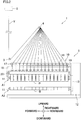
- FIG. 1 is a front elevation of a spun yarn take-up apparatus of the present embodiment
- FIG. 2 is a profile of the spun yarn take-up apparatus of the present embodiment
- FIG. 3 is a block diagram showing an electric configuration of the spun yarn winding apparatus.
- forward, rearward, leftward, rightward, upward, and downward directions shown in FIG. 1 and FIG. 2 will be referred to as forward, rearward, leftward, rightward, upward, and downward directions of the spun yarn take-up apparatus.
- the spun yarn take-up apparatus 1 is configured to take up yarns Y spun out from a spinning apparatus 2 and includes godet rollers 3 and 4 and a winding unit 5.
- the spinning apparatus 2 is provided above the spun yarn take-up apparatus 1 and is configured to spin out yarns Y which are made of synthetic filaments.
- the godet rollers 3 and 4 are provided below the spinning apparatus 2 and are rotationally driven by an unillustrated motor. The yarns Y spun out from the spinning apparatus 2 are wound onto the godet rollers 3 and 4 in this order, and are then sent to a winding unit 5 by the godet rollers 3 and 4.
- the winding unit 5 includes two spun yarn winding apparatuses 10 which are provided below the godet rollers 3 and 4.
- the two spun yarn winding apparatuses 10 are provided to oppose each other over a yarn path of the yarns Y which are sent from the godet rollers 3 and 4, so as to be symmetrical in the left-right direction.
- the yarns Y spun out from the spinning apparatus 2 are sent to the two spun yarn winding apparatuses 10 in a divided manner. For example, when 32 yarns Y are sent from the spinning apparatus 2, a half of, i.e., 16 yarns are wound by the left spun yarn winding apparatus 10, whereas the remaining 16 yarns are wound by the right spun yarn winding apparatus 10.
- the number of the yarns Y wound by the spun yarn winding apparatuses 10 is not limited to this.
- Each spun yarn winding apparatus 10 is configured to wind yarns Y onto bobbins B retained by a bobbin holder 11 so as to form packages P.
- Each spun yarn winding apparatus 10 is provided with two bobbin holders 11.
- Each bobbin holder 11 is a shaft member extending in the front-rear direction, and is cantilevered at its rear end portion by a turret 13 which is provided on a frame 12.
- the bobbin holder 11 is able to retain plural (16 in the present embodiment) bobbins B which are lined in the axial direction.
- the bobbin holder 11 is rotationally driven about its axis by a bobbin holder motor 14 (see FIG. 3 ).
- the turret 13 is a disc-shaped member rotatably attached to the frame 12, and is rotationally driven about its axis by a turret motor 15 (see FIG. 3 ). As the turret 13 rotates, the position of each the two bobbin holders 11 supported by the turret 13 is switched between an upper winding start position A1 and a lower replacement position A2. On the bobbin holder 11 at the winding start position A1, it is possible to start winding of yarns Y onto new bobbins B. Meanwhile, on the bobbin holder 11 at the replacement position A2, an operator is allowed to replace the bobbins B, i.e., to detach completed packages P and attach new bobbins B.
- the bobbins B are attachable and detachable from the front side of the bobbin holder 11, and are attached to the bobbin holder 11 such that the bobbin B attached first is the rearmost one whereas the bobbin B attached last is the frontmost one.
- the spun yarn winding apparatus 10 includes a supporting frame 16 which extends in the front-rear direction to be substantially parallel to the bobbin holder 11.
- the supporting frame 16 is cantilevered at its rear end portion by the frame 12.
- a guide supporter 17 is provided above the supporting frame 16.
- plural fulcrum guides 18 are provided to be lined up the front-rear direction to correspond to the respective bobbins B attached to the bobbin holder 11.
- plural traverse units 19 are provided to be lined up in the front-rear direction to correspond to the respective bobbins B attached to the bobbin holder 11.
- Each traverse unit 19 is configured to traverse the yarn Y in the front-rear direction about the corresponding fulcrum guide 18.
- the spun yarn winding apparatus 10 includes a contact roller 20 which is supported by the supporting frame 16 to be rotatable.
- the contact roller 20 is provided below the supporting frame 16.
- the contact roller 20 is rotationally driven by a contact roller motor 27 (see FIG. 3 ) about its axis, and makes contact with the outer circumferential surfaces of packages P retained by the bobbin holder 11 which is at the winding start position A1.
- a contact roller motor 27 see FIG. 3
- the spun yarn winding apparatus 10 starts the winding of yarns Y traversed by the traverse units 19, on new bobbins B attached to the bobbin holder 11 at the winding start position A1.
- the contact roller 20 is suitably moved up or down and/or the turret 13 is suitably rotationally driven while the yarns Y are wound. In this way, the packages P are formed in accordance with the increase in diameter of the packages P.
- the controller 21 rotationally drives the turret 13 to switch the positions of the two bobbin holders 11.
- the bobbin holder 11 at the replacement position A2 is moved to the winding start position A1, and winding of yarns Y onto the new bobbins B attached to this bobbin holder 11 starts.
- the bobbin holder 11 at the winding start position A1 is moved to the replacement position A2, and the packages P are detached and new bobbins B are attached.
- bobbins B onto which yarns Y are wound are switched to new bobbins B
- bobbins B onto which yarns Y are wound are switched from bobbins B (packages P) retained by one bobbin holder 11 newly moved to the replacement position A2 are switched to new bobbins B retained by the other bobbin holder 11 newly moved to the winding start position A1.
- FIG. 4 schematically shows the traverse unit 19 and a later-described yarn threading mechanism.
- FIG. 4 shows a state in which the turret 13 has just been rotated in order to switch bobbins B onto which yarns Y are wound to new bobbins B, i.e., a state in which yarn threading to the new bobbins B has not been done and the yarns Y are still connected to the packages P.
- the directions may be suitably rephrased as follows: the front-rear direction is rephrased as an axial direction, a front side is rephrased as a leading end side, and a rear side is rephrased as a base end side.
- members such as the frame 12, the supporting frame 16, and the contact roller 20 may not be shown.
- the traverse unit 19 includes a traverse guide 25 and two blade guides 26.
- the traverse guide 25 is a plate-shaped member having a guide edge 25a which extends in the axial direction.
- a yarn Y to be traversed is in contact with the guide edge 25a and is guided in the axial direction along the guide edge 25a.
- the two blade guides 26 are disposed to overlap each other in the thickness direction of the traverse guide 25 (i.e., the direction perpendicular to the plane of FIG. 4 ).
- the two blade guides 26 rotate in opposite directions about an axis which is parallel to the thickness direction of the traverse guide 25.
- the yarn Y in contact with the guide edge 25a of the traverse guide 25 is moved to the leading end side by one of the blade guides 26.
- the yarn Y is passed to the other blade guide 26.
- the yarn Y having been passed to the other blade guide 26 is moved to the base end side by the other blade guide 26.
- the yarn Y is passed to the one blade guide 26.
- the spun yarn winding apparatus 10 includes a yarn threading mechanism 30 which is configured to perform yarn threading into the slit S when a bobbin B onto which a yarn Y is wound is switched to a new bobbin B.
- the yarn threading mechanism 30 includes guides 31, a driving unit 32, a bobbin position sensor 22, and a guide position sensor 23.
- the yarn threading mechanism 30 is provided in the supporting frame 16.
- Each guide 31 is hook-shaped to be able to capture the yarn Y.
- One guide 31 is provided for one bobbin B.
- the guides 31 are lined up at equal intervals in the axial direction to correspond to the respective bobbins B.
- the driving unit 32 is provided to move the guides 31 in the axial direction.
- the driving unit 32 includes a supporting member 33 extending in the axial direction and a mover 34 configured to move the supporting member 33 in the axial direction.
- the guides 31 are lined up in the axial direction at the same intervals as the lengths (standard size) of the bobbins B and are fixed to the supporting member 33.
- the mover 34 moves the supporting member 33 in the axial direction, the guides 31 are moved together in the axial direction.
- the mover 34 may be differently arranged on condition that the moving distance of the supporting member 33 in the axial direction is controllable.
- the mover 34 is a combination of a servo motor and a ball screw, or a linear motor. Operations of the driving unit 32 (mover 34) are controlled by the controller 21 (see FIG. 3 ).
- the guide 31 While the yarn Y is wound onto the bobbin B, the guide 31 is on standby at a yarn threading position (indicated by a full line in FIG. 4 ) which is on the leading end side of the traversal range T, in order to prevent the traversed yarn Y from being hooked. Meanwhile, when the bobbin B onto which the yarn Y is wound is switched to a new bobbin B, the guide 31 is moved from the yarn threading position to a capturing position (indicated by a dotted lined in FIG. 4 ) in the traversal range T, in order to capture the yarn Y which is connected to a package P and being traversed.
- the yarn threading position of the guide 31 is identical with the position of the slit S of the corresponding bobbin B. On this account, when the guide 31 having captured the yarn Y at the capturing position returns to the yarn threading position, the yarn Y captured by the guide 31 is threaded into the slit S.
- the yarn threading position of the guide 31 may not be at the same position as the slit S. This yarn threading position may be at a predetermined position on the leading end side of the slit S (e.g., at a predetermined position which falls within a range of 0 to 5mm on the leading end side of the slit S).
- the bobbin position sensor 22 and the guide position sensor 23 are attached to a front end portion of the supporting frame 16 (see FIG. 2 ).
- the bobbin position sensor 22 is an optical sensor which is able to measure the distance a to the leading end surface of a bobbin B which is on the most leading end side among the bobbins B retained by the bobbin holder 11 at the winding start position A1. As the bobbin position sensor 22 measures the distance a, it is possible to grasp the length of the bobbin B and the location in the axial direction of the slit S.
- the guide position sensor 23 is an optical sensor which is able to measure the distance b to a guide 31 which is on the most leading end side.
- the bobbin position sensor 22 and the guide position sensor 23 may be differently arranged on condition that the locations of the bobbin B and the guide 31 can be measured.
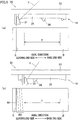
- FIG. 5(a), FIG. 5(b) , FIG. 6(a), and FIG. 6(b) is a schematic diagram showing the basic operation of the yarn threading mechanism 30. While each of FIG. 5(a), FIG. 5(b) , FIG. 6(a), and FIG. 6(b) shows an operation of one guide 31 corresponding to one bobbin B, the other guides 31 operate in the same way.
- FIG. 5(a) shows a state immediately after the rotation of the turret 13. In this state, the guide 31 is on standby at the yarn threading position, and the yarn Y is still connected to the package P and being traversed by the traverse unit 19. The bobbin holder 11 at the winding start position A1 is being rotationally driven.
- the controller 21 moves the guide 31 to the capturing position by driving the mover 34 and moving the supporting member 33 to the base end side. As a result, the traversed yarn Y is hooked and captured by the guide 31. Subsequently, as shown in FIG. 6(a) , the controller 21 returns the guide 31 having captured the yarn Y to the yarn threading position by driving the mover 34 and moving the supporting member 33 to the leading end side. As a result, the yarn Y is hooked by the slit S. As the tension of the yarn Y increases, the yarn Y is cut and winding of the yarn Y onto the new bobbin B starts.
- bunch winding W1 is formed at the slit S as shown in FIG. 6(b) .
- the controller 21 moves the guide 31 toward the capturing position again, as shown in FIG. 6(b) .
- tail winding W2 is formed between the slit S and the traversal range T. A part of the yarn Y at the tail winding W2 is used for connecting yarns Y of plural packages P, in a later process.
- the yarn Y is detached from the guide 31 and captured by the blade guide 26 of the traverse unit 19.
- the controller 21 returns the guide 31 from the capturing position to the yarn threading position.
- the arrangement for detaching the yarn Y from the guide 31 while the guide 31 moves to the capturing position may be an arrangement described in Patent Literature 1, for example.
- the above-described yarn threading position of the guide 31 is determined with the assumption that the length of the bobbin B is identical with a predetermined standard size. To put it differently, as shown in FIG. 4 , when the length of the bobbin B is identical with the standard size, the yarn threading position of each guide 31 is identical with the position of the slit S in the bobbin B. However, when the length of the bobbin B has a dimensional error from the predetermined standard size, there is a difference between the yarn threading position of the guide 31 and the position of the slit S in the axial direction, with the result that the yarn Y cannot be threaded into the slit S even if the guide 31 is moved to the yarn threading position.
- This problem is particularly conspicuous when many bobbins B are attached to one bobbin holder 11 as in the present embodiment. This is because bobbins B of the same lot are typically used simultaneously, and dimensional errors of bobbins B attached to one bobbin holder 11 are often substantially identical with each other. The dimensional errors are therefore accumulated when the bobbins B are lined up in the axial direction, a positional error of the guide 31 relative to the slit S increases toward the leading end side, and hence a failure in yarn threading is likely to occur in such a case. This problem may occur not only when the bobbins B involve dimensional errors but also when the mounting accuracy of the guides 31 is low and the guides 31 are deviated from the intended locations in the axial direction. On this account, the present embodiment is arranged so that a failure in yarn threading is restrained by adjusting the yarn threading position of the guide 31 based on the distances a and b detected by the bobbin position sensor 22 and the guide position sensor 23.
- FIG. 7(a) to FIG. 7(c) is a schematic diagram showing position adjustment of the guide 31 when the bobbin B is longer than the standard size
- FIG. 8(a) to FIG. 8(c) is a schematic diagram showing position adjustment of the guide 31 when the bobbin is shorter than the standard size.
- the guide 31 is at the yarn threading position.
- the distance b detected by the guide position sensor 23 is constant at b0 which is the distance when the guide 31 is at the intended yarn threading position.
- FIG. 7(a) and FIG. 8(a) shows a case where the length of the bobbin B is identical with the standard size.
- the distance a detected by the bobbin position sensor 22 in this case is referred to a a0.
- the position adjustment of the guide 31 when the bobbin B is longer than the standard size As shown in FIG. 7(a) , when the bobbin B is of the standard size, the position of the slit S of the bobbin B coincides with the yarn threading position of each guide 31 in the axial direction. Meanwhile, when the bobbin B is longer than the standard size as shown in FIG. 7(b) , the yarn threading position of each guide 31 is deviated to the base end side relative to the corresponding slit S. The distance a1 detected by the bobbin position sensor 22 in this case is shorter than a0.
- each guide 31 returning from the capturing position to the yarn threading position after the capture of the yarn Y does not reach the slit S, with the result that yarn threading to the bobbins B cannot be done.
- the controller 21 moves the supporting member 33 toward the leading end only by (a0-a1) as shown in FIG. 7(c) .
- the yarn threading position of the guide 31 which is on the most leading end side corresponds to the position of the slit S.
- the yarn threading positions of the other guides 31 are deviated to the leading end side as compared to the corresponding slits S, but these deviations do not cause a big problem. This is because, when the guide 31 returns from the capturing position to the yarn threading position, the yarn Y passes the slit S and hence the yarn Y is likely to be threaded into the slit S.
- the distance with which the supporting member 33 is moved to the leading end side may be longer than (a0-a1).
- the position adjustment of the guide 31 when the bobbin B is shorter than the standard size As shown in FIG. 8(a) , when the bobbin B is of the standard size, the position of the slit S of the bobbin B corresponds to the yarn threading position of each guide 31 in the axial direction. Meanwhile, when the bobbin B is shorter than the standard size as shown in FIG. 8(b) , the yarn threading position of each guide 31 is deviated to the leading end side relative to the corresponding slit S. The distance a2 detected by the bobbin position sensor 22 in this case is longer than a0.
- the position adjustment of the guide 31 may not be carried out when the bobbin B is shorter than the standard size (i.e., a2>a0).
- the position adjustment of the guide 31 is preferably performed only when (a2-a0) is larger than a predetermined threshold.
- the position adjustment of the guide 31 may be always performed in a case of a2>a0.
- the controller 21 moves the supporting member 33 to the base end side as shown in FIG. 8(c) .
- An adjustment margin with which the supporting member 33 can be moved to the base end side without causing the yarn threading position of the guide 31 on the most base end side to become on the base end side of the slit S is a value calculated by dividing (a2-a0) by the number of the bobbins B.
- the adjustment margin is (a2-a0)/16 in the present embodiment. While the supporting member 33 is moved to the base end side by (a2-a0)/16 in this case, the moving distance may be shorter than (a2-a0)/16.
- the success rate of the yarn threading is improved by suitably adjusting the yarn threading position of the guide 31 in accordance with the distance a measured by the bobbin position sensor 22. It is noted that the distance b measured by the guide position sensor 23 is assumed to be unchanged in the examples shown in FIG. 7 and FIG. 8 . When the position of the guide 31 is deviated due to a reason of assembling accuracy, etc., the moving distance of the guide 31 (supporting member 33) is adjusted in consideration of the distance b measured by the guide position sensor 23.
- FIG. 9 is a flowchart of a series of steps executed when a bobbin B on which a yarn Y is wound is switched to a new bobbin B.
- the controller 21 rotates the turret 13 to switch the positions of the two bobbin holders 11 (step S10).
- the bobbin position sensor 22 and the guide position sensor 23 measure the distances a and b and the controller 21 stores the measured values (step S11).
- the controller 21 determines whether the yarn Y can be wound in a predetermined winding allowable range of the bobbin B, based on the measurement result of the distance a by the bobbin position sensor 22 (step S12).
- the controller 21 executes the determination in the step S12.
- the controller 21 stops the components such as the bobbin holder 11 and the traverse units 19 to stop the winding of the yarn Y (step S13).
- the controller 21 determines whether the length of the bobbin B falls within a predetermined dimensional tolerance range, based on the result of measurement of the distance a by the bobbin position sensor 22 (step S14). For example, when the dimensional tolerance of one bobbin B is set at ⁇ 0.2mm, it is considered that the length of the bobbin B falls within the dimensional tolerance range if the distance a falls within the range (a0 ⁇ 3.2)mm, in the present embodiment in which 16 bobbins B are attached. The winding of the yarn Y is possible even when the length of the bobbin B does not fall within the dimensional tolerance range, but this state should not be tolerated.
- the controller 21 activates an alarm 90 (see FIG. 3 ) provided in the spun yarn winding apparatus 10 (step S15). This makes it possible to inform the operator that the length of the bobbin B does not fall within the dimensional tolerance range, and hence the quality control of the bobbins B can be properly done.
- the controller 21 determines whether the position adjustment of the guide 31 is necessary, based on the stored measurement results of the distances a and b (step S16). As described above, when the yarn threading position of the guide 31 is on the base end side relative to the slit S (see FIG. 7(b) ) or when the yarn threading position of the guide 31 is on the leading end side relative to the slit S over a predetermined threshold (see FIG. 8(b) ), it is determined that the position adjustment of the guide 31 is necessary.
- the controller 21 When the position adjustment of the guide 31 is necessary (YES in the step S16), the controller 21 performs the position adjustment of the guide 31 (step S17) and then performs yarn threading to a new bobbin B by suitably driving the yarn threading mechanism 30 (step S18). Meanwhile, when the position adjustment of the guide 31 is unnecessary (NO in the step S16), yarn threading to a new bobbin B is performed without the position adjustment of the guide 31 (step S18).
- the controller 21 accumulates data regarding the distance a measured by the bobbin position sensor 22 and the distance b measured by the guide position sensor 23. Based on the accumulated data, the controller 21 performs quality control of the bobbin B. For example, when it is estimated that the dimensional error of the length of the bobbin B has gradually increased and the length of the bobbin B which will be newly attached is likely to be out of the dimensional tolerance range, the operator is notified of this estimation by the alarm 90.
- the yarn threading mechanism 30 includes the guides 31 by which the yarns Y are threaded into the slits S formed in the bobbins B, the driving unit 32 configured to move the guides 31 in the axial direction, and the bobbin position sensor 22 configured to detect the position in the axial direction of the predetermined part of the bobbins B retained by the bobbin holder 11. Based on the position of the new bobbin B detected by the bobbin position sensor 22, the position in the axial direction of the guide 31 is adjusted.
- the positional deviation is restrained by performing the position adjustment of the guide 31. On this account, even if the length of the bobbin B has a dimensional error, the yarn is successfully threaded into the slit S at the time of the switching to the new bobbin B.
- the controller 21 when the guide 31 having captured the yarn Y is moved toward the slit S, the controller 21 performs adjustment in such a manner that the guide 31 stops at the same position as the slit S in the axial direction or at a predetermined position over the slit S. As the guide 31 having captured the yarn Y is moved to the same position as the slit S or the predetermined position over the slit S, threading of the yarn Y into the slit S is ensured.
- the bobbins B are attached to or detached from the bobbin holder 11 from the leading end side (one end side) in the axial direction of the bobbin holder 11, and the bobbin position sensor 22 detects the position of the leading end surface of the bobbin B which is on the most leading end side among the bobbins B.
- the bobbins B are detached from or attached to the bobbin holder 11 from the leading end side
- the bobbin B attached first is on the most base end side (the other end side) whereas the bobbin B attached last is on the most leading end side.
- the dimensional errors are accumulated toward the one end side and the positional deviation is most significant at the bobbin B on the most leading end side. It is therefore possible to accurately grasp the deviations in relative position between the guides 31 and the bobbins B by detecting the position of the leading end surface of the bobbin B on the most leading end side.
- the bobbin position sensor 22 detects the position of the leading end surface of the bobbin B while the new bobbin B is rotating. For example, when the leading end surface of the bobbin B is irregular, a detection error in the position of the bobbin B is significant if the detection is performed at a distinctively irregular part. In this regard, the influence of the distinctive irregularity is restrained by detecting the position of the leading end surface while the bobbin B is rotating.
- the bobbin holder 11 is movable at least between the winding start position A1 at which the winding of the yarns Y onto the new bobbins B starts and the replacement position A2 at which the bobbins B are replaced, and the bobbin position sensor 22 detects the position of the leading end surface of the bobbin B when the bobbin holder 11 is at the winding start position A1.
- the bobbin position sensor 22 is provided in the vicinity of the winding start position A1, and is therefore far from the replacement position A2. In this way, it is possible to easily provide the bobbin position sensor 22 not to obstruct the replacement of the bobbins B.
- the alarm 90 is provided to notify the operator of a predetermined state.
- the controller 21 activates the alarm 90. This arrangement allows the operator to promptly know that the length of the new bobbin B does not fall within the dimensional tolerance range, and this problem is suitably dealt with.
- the controller 21 terminates the winding of the yarn Y when it is determined based on a detection result of the bobbin position sensor 22 that the yarn Y cannot be wound within the predetermined winding allowable range of the new bobbin B. This arrangement prevents the formation of a defective package in which the yarn Y is not wound within the winding allowable range.
- the controller 21 accumulates detection results of the bobbin position sensor 22 and performs quality control of the bobbins B based on the accumulated data. This makes it possible to grasp information such as tendency of the lengths of the bobbins B, and hence the quality control of the bobbins B is further ensured.
- the driving unit 32 includes the supporting member 33 supporting the guides 31 and the mover 34 configured to move the guides 31 together by moving the supporting member 33 in the axial direction. This arrangement simplifies the device configuration as compared to cases where each guide 31 is individually moved.
- the guide position sensor 23 is further provided to detect the position in the axial direction of the predetermined part of the guides 31, and the controller 21 adjusts the position in the axial direction of the guide 31 based on a detection result of the bobbin position sensor 22 and relative positions of the guide 31 and the new bobbin B in the axial direction, which are obtained from a detection result of the guide position sensor 23.
- the guide 31 may be deviated from the intended location in the axial direction. Even in such a case, the guide position sensor 23 makes it possible to grasp the relative positions of the guide 31 and the new bobbin B, and hence the position adjustment of the guide 31 can be suitably done.
- FIG. 10(a) and FIG. 10(b) is a schematic diagram of a yarn threading mechanism according to a first modification.
- FIG. 10(a) and FIG. 10(b) shows a case where the bobbin B is shorter than the standard size.
- FIG. 10(a) shows a state before the adjustment of a yarn threading position of a guide 41
- FIG. 10(b) shows a state after the adjustment of the yarn threading position of the guide 41.
- a yarn threading mechanism 40 of the first modification includes guides 41, nuts 42, a screw 43, a mover 44, and a rotary device 45.
- the nuts 42, the screw 43, the mover 44, and the rotary device 45 constitute the driving unit of the present invention.
- the nuts 42, the screw 43, and the rotary device 45 constitute a pitch changing mechanism of the present invention. This pitch changing mechanism makes it possible to change the intervals of the guides 41 in the axial direction.
- the screw 43 extends in the axial direction, and plural male screw parts 43 are formed on the screw 43 to correspond to the respective nuts 42 and to be lined up in the axial direction.
- Each guide 41 is attached to the screw 43 by the nut 42 which is screwed with the male screw part 43a.
- FIG. 11 is a perspective view of the mover 44 of the first modification.
- the mover 44 is provided to move the screw 43 in the axial direction, and includes a cylinder 46 and an engaging member 47.
- a rod 46a of the cylinder 46 is extended and shortened in the axial direction, and the engaging member 47 is fixed to a leading end portion of the rod 46a.
- the operation of the cylinder 46 is controlled by a controller 21.
- An annular groove 43b is formed at part of the screw 43. Meanwhile, a U-shaped portion 47a which is a U-shaped cutout is formed in the engaging member 47. While in FIG. 11 the engaging member 47 is detached from the screw 43 for showing the structure in a simplified manner, actually the U-shaped portion 47a of the engaging member 47 is engaged with the annular groove 43b.
- the inner diameter of the U-shaped portion 47a is arranged to be slightly longer than the outer diameter of the annular groove 43b. With this arrangement, the screw 43 is able to rotate about its axis even when the engaging member 47 is engaged with the screw 43.
- the engaging member 47 moves in the axial direction.
- the engaging member 47 presses a side face of the annular groove 43b and hence the screw 43 moves in the axial direction.
- the specific arrangement of the mover 44 is not limited to this, and the mover 44 may be differently arranged on condition that the screw 43 is rotatable and movable in the axial direction.
- the rotary device 45 is provided to rotate the screw 43 about its axis and includes a motor 48 and a rod 49.
- the rod 49 is connected to an output shaft 48a of the motor 48.
- the rod 49 rotates about the axis of the screw 43 when the motor 48 is rotationally driven.
- the operation of the motor 48 is controlled by a controller 21.
- a long hole 43c is formed in a leading end portion of the screw 43 to be long in the axial direction.
- the rod 49 of the rotary device 45 penetrates the long hole 43c.
- the rod 49 presses a side face of the long hole 43c, with the result that rotational torque is applied to the screw 43 and the screw 43 rotates about its axis.
- the rod 49 is able to perform relative movement in the axial direction in the long hole 43c. On this account, the rod 49 does not obstruct the movement of the screw 43 in the axial direction by the mover 44.
- the controller 21 rotationally drives the motor 48, rotational torque is transferred from the rod 49 to the screw 43 and the screw 43 is rotated about its axis.
- the specific arrangement of the rotary device 45 is not limited to this.
- the rotary device 45 may be differently arranged on condition that the screw 43 is movable in the axial direction and rotatable about is axis.
- each nut 42 has a corresponding female screw.
- FIG. 12(a) and FIG. 12(b) are a schematic diagram of a yarn threading mechanism according to a second modification.
- FIG. 12(a) and FIG. 12(b) shows a case where the bobbin B is shorter than the standard size.
- FIG. 12(a) shows a state before the adjustment of a yarn threading position of a guide 51
- FIG. 12(b) shows a state after the adjustment of the yarn threading position of the guide 51.
- a yarn threading mechanism 50 of the second modification includes guides 51, a pantograph mechanism 52, a telescopic device 53, a base member 54, and a mover 55.
- the pantograph mechanism 52, the telescopic device 53, the base member 54, and the mover 55 constitute the driving unit of the present invention.
- the pantograph mechanism 52, the telescopic device 53, and the base member 54, constitute the pitch changing mechanism of the present invention. This pitch changing mechanism makes it possible to change the intervals of the guides 51 in the axial direction.
- the pantograph mechanism 52 includes links 52a and joints 52b, and is extendable and retractable in the axial direction.
- the pantograph mechanism 52 is not detailed because it is a known link mechanism.
- the telescopic device 53 is provided to extend and shorten the pantograph mechanism 52, and is formed of a cylinder, for example.
- the pantograph mechanism 52 and the telescopic device 53 are mounted on the base member 54.
- the mover 55 is provided to move the base member 54 in the axial direction, and is formed of a cylinder, for example. Operations of the telescopic device 53 and the mover 55 are controlled by a controller 21.
- a joint 52b which is on the most base end side in the pantograph mechanism 52 is fixed to the base member 54. Meanwhile, a joint 52b which is on the most leading end side is connected to the telescopic device 53.
- the guides 51 are provided at equal intervals in the axial direction and are attached to the respective joints 52b via attaching members 56. With this arrangement, when the joint 52b on the most leading end side is moved in the axial direction by the telescopic device 53, the pantograph mechanism 52 is accordingly extended or shortened. In this way, it is possible to change the intervals of the guides 51 while maintaining the intervals to be identical with one another.
- the yarn threading position of each guide 41 is on the leading end side as compared to the corresponding slit S.
- FIG. 12(b) it is possible to adjust the yarn threading position of each guide 51 to be positionally identical with the corresponding slit S by extending or shortening the pantograph mechanism 52 by the telescopic device 53 in order to move each guide 51 toward the base end.
- the bobbin B is longer than the standard size, it is possible to similarly adjust the yarn threading position of each guide 51 to be positionally identical with the corresponding slit S.
- FIG. 13(a) and FIG. 13(b) is a schematic diagram of a yarn threading mechanism according to a third modification.
- FIG. 13(a) and FIG. 13(b) shows a case where the bobbin B is shorter than the standard size.
- FIG. 13(a) shows a state before the adjustment of a yarn threading position of a guide 61
- FIG. 13(b) shows a state after the adjustment of the yarn threading position of the guide 61.
- a yarn threading mechanism 60 of the third modification includes guides 61, nuts 62, a screw 63, a mover 64, and a rotary device 65.
- the nuts 62, the screw 63, the mover 64, and the rotary device 65 constitute the driving unit of the present invention.
- the mover 64 and the rotary device 65 are not detailed because they are structurally identical with the mover 44 and the rotary device 45 of the first modification.
- plural (16) guides 61 are grouped into a first group constituted by a half of (8) guides 61 on the leading end side and a second group constituted by the other half of (8) guides 61 on the base end side.
- the guides 61 belonging to the first group are arranged to be movable together in the axial direction relative to the screw 63.
- the guides 61 belonging to the second group are arranged to be immovable in the axial direction relative to the screw 63.
- At least one guide 61 (the guide 61 on the most base end side in this modification) is attached to the screw 63 via the nut 62.
- the nut 62 is screwed to a male screw part 63a formed on the screw 63.
- the remaining guides 61 of the first group are attached to the screw 63 via ring members 66.
- Each ring member 66 is loosely fitted to the screw 63, and is rotatable relative to the screw 63 and is movable in the axial direction relative to the screw 63.
- the nut 62 and each ring member 66 are connected to each other by a connection member 67 to be able to move together in the axial direction.
- All of the guides 61 belonging to the second group are attached to the screw 63 via the ring members 68.
- Each ring member 68 is, for example, engaged with an unillustrated annular groove formed in the screw 63, with a slight gap therebetween.
- the ring member 68 is rotatable relative to the screw 63 but cannot relatively move in the axial direction. With this arrangement, the guides 61 belonging to the second group do not move in the axial direction when the screw 63 is rotated about its axis by the rotary device 65.
- the yarn threading position of each guide 41 is on the leading end side as compared to the corresponding slit S.
- the screw 63 is moved toward the base end by the mover 64 so that the yarn threading position of the guide 61 on the most base end side is positionally identical with the corresponding slit S.
- the state shown in FIG. 8(c) is achieved.
- the screw 63 is rotated about its axis by the rotary device 65 so that the yarn threading position of the guide 61 on the most base end side in the first group is positionally identical with the corresponding slit S.
- the guides 61 of the first group are movable in the axial direction relative to the screw 63, the degree of freedom in position adjustment of each guide 61 is improved as compared to cases where the positions of all guides 61 are only adjustable together by the movement of the screw 63. While the guides 61 are grouped into the first group and the second group in the present modification, the guides may be grouped into three or more groups.
- the guide position sensor 23 is provided to detect the position of the guide 31, this guide position sensor 23 may be omitted. Omission of the guide position sensor 23 does not cause any particular problem when the guide 31, the supporting member 33, and the mover 34 are precisely mounted, because the position of the guide 31 is unlikely to be deviated.
- the bobbin position sensor 22 detects the position of the leading end surface of the bobbin B while the bobbin B is rotating.
- the bobbin position sensor 22 may detect the position of the leading end surface of the bobbin B while the bobbin B (bobbin holder 11) does not rotate. Because the end face of the bobbin B is only as thick as the hollow cylindrical bobbin B, the detection of the position of the end face of the bobbin B may not be successfully done when the bobbin B rotates and vibrates. On this account, the position of the end face is certainly detected when the position of the end face is detected when the bobbin B does not rotate.
- the bobbin position sensor 22 measures the distance a to the leading end surface of the bobbin B on the most leading end side, i.e., measures the position of the leading end surface of the bobbin B.
- the location of the position detection by the bobbin position sensor 22 is not limited to this, and the position of another part of the bobbins B may be detected. The same applies to the guide position sensor 23.
- the bobbin position sensor 22 and the guide position sensor 23 are fixed to the supporting frame 16.
- the bobbin position sensor 22 and the guide position sensor 23 may be arranged to be movable.
- the bobbin position sensor 22 is arranged to be movable between a bobbin detection position where the position of a new bobbin B is detected and a guide detection position where the position of the guide 31 is detected, it is possible to omit the guide position sensor 23 and cause the bobbin position sensor 22 to also function as the guide position sensor 23. This makes it possible to reduce the number of components and restrain the costs.
- all guides 31 are moved together in the axial direction by moving the supporting member 33 by the mover 34.
- a driving unit may be provided for each of the guides 31 to allow each guide 31 to individually move.
- each bobbin B is attached to the bobbin holder 11 so that the slit S formed in the bobbin B is on the leading end side.
- each bobbin B may be attached to the bobbin holder 11 so that the slit S is on the base end side.
- the basic idea at the position adjustment of the guide 31 in the embodiment above is also applicable to this case.
- the spun yarn winding apparatuses 10 are provided in the winding unit 5 and the spun yarn winding apparatuses 10 are substantially symmetrical in the left-right direction over the yarn path of the yarns Y supplied from the godet rollers 3 and 4 and are provided in one frame 12, the disclosure is not limited to this arrangement.
- Two spun yarn winding apparatuses 10 may not be substantially symmetrical in the left-right direction, each spun yarn winding apparatus 10 may be individually provided, or only one spun yarn winding apparatus 10 may be provided.
- each spun yarn winding apparatus 10 While in the embodiment above two bobbin holders 11 are provided in each spun yarn winding apparatus 10, three or more bobbin holders 11 may be provided.
Landscapes
- Engineering & Computer Science (AREA)
- Textile Engineering (AREA)
- Mechanical Engineering (AREA)
- Winding Filamentary Materials (AREA)
- Guides For Winding Or Rewinding, Or Guides For Filamentary Materials (AREA)
- Replacing, Conveying, And Pick-Finding For Filamentary Materials (AREA)
Abstract
Description
- The present invention relates to a spun yarn winding apparatus including bobbin holders. The spun yarn winding apparatus includes a yarn threading mechanism which threads yarns into slits formed on the outer circumferential surfaces of new bobbins, when bobbins on which yarns are wound are switched from bobbins retained by one bobbin holder to new bobbins retained by another bobbin holder.
- For example, Patent Literature 1 (Japanese Laid-Open Patent Publication No.
2017-154891 - The above-described guide is controlled with the assumption that the length of the bobbin is identical with a predetermined standard size. On this account, when the length of the bobbin has a dimensional error from the predetermined standard size, there is a difference between relative positions of the guide and the bobbin in the axial direction, with the result that the yarn cannot be threaded into the slit. This problem is particularly conspicuous when many bobbins are attached to one bobbin holder. This is because bobbins of the same lot are typically used simultaneously, and dimensional errors of bobbins attached to one bobbin holder are often substantially identical with each other. The dimensional errors are therefore accumulated when the bobbins are lined up in the axial direction, and a failure in yarn threading is likely to occur in such a case.
- In consideration of the problem above, an object of a spun yarn winding apparatus of the present invention is to successfully thread a yarn into a slit when a bobbin to which the yarn is wound is switched to a new bobbin, even if the length of the bobbin has a dimensional error from a predetermined standard size.
- The present invention relates to a spun yarn winding apparatus configured to wind yarns spun out from a spinning apparatus onto bobbins, which includes: bobbin holders by which the bobbins are retained to be lined up in an axial direction; a traverse unit which is configured to traverse the yarns; a yarn threading mechanism which is configured to thread the yarns into slits formed in outer circumferential surfaces of new bobbins, when bobbins on which yarns are wound are switched from bobbins retained by one of the bobbin holders to the new bobbins retained by another one of the bobbin holders; and a controller, the yarn threading mechanism including: guides which are provided to correspond to the respective new bobbins and are movable in the axial direction, the guides moving toward the corresponding slits after capturing the yarns traversed by the traverse unit and then threading the yarns into the slits; a driving unit configured to move the guides in the axial direction; and a bobbin position sensor configured to detect a position in the axial direction of a predetermined part of the new bobbins, the controller adjusting positions in the axial direction of the guides by controlling the driving unit based on a detection result of the bobbin position sensor.
- According to the present invention, based on the position of the new bobbin detected by the bobbin position sensor, the position in the axial direction of the guide is adjusted. When the length of the new bobbin has a dimensional error with respect to the predetermined standard size and the guide is positionally deviated in the axial direction relative to the slit of the new bobbin, the positional deviation is restrained by performing the position adjustment of the guide. On this account, according to the present invention, even if the length of the bobbin has a dimensional error, the yarn is successfully threaded into the slit at the time of the switching to the new bobbin.
- The spun yarn winding apparatus of the present invention may be arranged such that, when the guides having captured the yarns are moved toward the corresponding slits, the controller performs adjustment in such a manner that the guides stop at the same positions as the corresponding slits in the axial direction or at predetermined positions over the corresponding slits.
- As the guide having captured the yarn is moved to the same position as the slit or the predetermined position over the slit, threading of the yarn into the slit is ensured.
- The spun yarn winding apparatus of the present invention may be arranged such that the bobbins are attached and detached from one end side of each of the bobbin holders in the axial direction, and the bobbin position sensor detects a position of an end face on the one end side of a bobbin which is closest to the one end of the corresponding bobbin holder among the new bobbins.
- When the bobbins are detached from or attached to the bobbin holder from one end side, the bobbin attached first is closest to the other end whereas the bobbin attached last is closest to the one end. As a result, the dimensional errors are accumulated toward the one end side and the positional deviation is most significant at the bobbin closest to the one end. It is therefore possible to accurately grasp the deviations in relative position between the guides and the bobbins by detecting the position of the end face on the one end side of the bobbin which is closest to the one end.
- The spun yarn winding apparatus of the present invention may be arranged such that the bobbin position sensor detects the position of the end face when the new bobbins do not rotate.
- Because the end face of the bobbin is only as thick as the bobbin, the detection of the position of the end face may not be successfully done when the bobbin rotates and vibrates. On this account, the position of the end face is certainly detected when the position of the end face is detected when the bobbin does not rotate.
- The spun yarn winding apparatus of the present invention may be arranged such that the bobbin position sensor detects the position of the end face when the new bobbins are rotating.
- For example, when the end face of the bobbin is irregular, a detection error in the position of the bobbin is significant if the detection is performed at a distinctively irregular part. In this regard, the influence of the distinctive irregularity is restrained by detecting the position of the end face while the bobbin is rotating.
- The spun yarn winding apparatus of the present invention may be arranged such that each of the bobbin holders is movable at least between a winding start position where winding of the yarns onto the new bobbins starts and a replacement position where the bobbins are replaced, and the bobbin position sensor detects the position of the end face when the another one of the bobbin holders is at the winding start position.
- With this arrangement, the bobbin position sensor is provided in the vicinity of the winding start position, and is therefore far from the replacement position. In this way, it is possible to easily provide the bobbin position sensor not to obstruct the replacement of the bobbins.
- The spun yarn winding apparatus of the present invention may be arranged such that an alarm is provided to notify an operator of a predetermined state, and the controller activates the alarm when it is determined based on a detection result of the bobbin position sensor that the length of each of the new bobbins does not fall within a predetermined dimensional tolerance range.
- This arrangement allows the operator to promptly know that the length of the new bobbin does not fall within the dimensional tolerance range, and this problem is suitably dealt with.
- The spun yarn winding apparatus of the present invention may be arranged such that the controller terminates winding of the yarns when it is determined based on a detection result of the bobbin position sensor that each of the yarns cannot be wound within a predetermined winding allowable range on each of the new bobbins.
- This arrangement prevents the formation of a defective package in which the yarn is not wound within the winding allowable range.
- The spun yarn winding apparatus of the present invention may be arranged such that the controller accumulates detection results of the bobbin position sensor and performs quality control of the bobbins based on accumulated data.
- This makes it possible to, for example, grasp information such as tendency of the lengths of the bobbins, and hence the quality control of the bobbins is further ensured.
- The spun yarn winding apparatus of the present invention may be arranged such that the driving unit includes: a supporting member which supports the guides; and a mover which is configured to move the guides together in the axial direction by moving the supporting member in the axial direction.
- This arrangement simplifies the device configuration as compared to cases where each guide is individually moved.
- The spun yarn winding apparatus of the present invention may be arranged such that the driving unit includes a pitch changing mechanism which is configured to change intervals in the axial direction of the guides.
- Such a pitch changing mechanism allows the position of each guide to coincide with the position of the slit, with the result that the success rate of the yarn threading is improved.
- The spun yarn winding apparatus of the present invention may be arranged such that the pitch changing mechanism includes: a screw which is the supporting member, male screw parts being formed on the screw to correspond to the respective guides and to be lined up in the axial direction; nuts which are screwed to the respective male screw parts, the guides being attached to the respective nuts; and a rotary device configured to move the nuts in the axial direction relative to the screw by rotating the screw about an axis of the screw, the male screw parts are arranged so that, when leads of two neighboring male screw parts are compared with each other, the lead of one screw part on one end side in the axial direction is longer than or shorter than the lead of the other screw part.
- This arrangement makes it possible to arrange the position of each guide to coincide with the position of the slit by rotating the screw.
- The spun yarn winding apparatus of the present invention may be arranged such that the pitch changing mechanism includes: a pantograph mechanism extendable and contractible in the axial direction; a telescopic device provided to extend and shorten the pantograph mechanism; and a base member which is the supporting member and on which the pantograph mechanism and the telescopic device are mounted, the guides being attached to the pantograph mechanism to be lined up in the axial direction.
- This arrangement makes it possible to arrange the position of each guide to coincide with the position of the slit by adjusting the extension amount of the pantograph mechanism.
- The spun yarn winding apparatus of the present invention may be arranged such that the driving unit is arranged to allow at least one of the guides to be movable in the axial direction relative to the supporting member.
- When at least one of the guides is movable in the axial direction relative to the supporting member, the degree of freedom in position adjustment of each guide is improved as compared to cases where the positions of all guides are only adjustable together by the movement of the supporting member.
- The spun yarn winding apparatus of the present invention may be arranged such that the driving unit includes: a screw which is the supporting member, a male screw part being formed at part in the axial direction of the screw; a nut which is screwed to the male screw part, one of the guides being attached to the nut; and a rotary device configured to move the nut in the axial direction relative to the screw by rotating the screw about an axis of the screw, the guides being grouped at least into: a first group which includes the guide attached to the nut, the guides in the first group being connected to one another so as to be movable together in the axial direction relative to the screw; and a second group which does not include the guide attached to the nut, the guides in the second group being immovable in the axial direction relative to the screw.
- Because this arrangement allows the guides in the first group and the guides in the second group to be different in moving distance in the axial direction, the degree of freedom in position adjustment of each guide is improved.
- The spun yarn winding apparatus of the present invention may be arranged such that the driving unit is individually provided for each of the guides.
- With this arrangement, because each guide is adjustable to an optimal position in accordance with the corresponding slit, success of yarn threading is ensured.
- The spun yarn winding apparatus of the present invention may further include a guide position sensor configured to detect a position in the axial direction of a predetermined part of the guides, the controller adjusting the positions in the axial direction of the guides based on relative positions of the guides and the new bobbins in the axial direction, which are obtained from a detection result of the bobbin position sensor and a detection result of the guide position sensor.
- When, for example, the mounting accuracy of the guide is low, the guide may be deviated from the intended location in the axial direction. Even in such a case, the guide position sensor makes it possible to grasp the relative positions of the guide and the new bobbin, and hence the position adjustment of the guide can be suitably done.
- The spun yarn winding apparatus of the present invention may be arranged such that the bobbin position sensor is movable between a bobbin detection position where the position of the predetermined part of the new bobbins is detected and a guide detection position where the position of the predetermined part of the guides is detected, the bobbin position sensor being also used as the guide position sensor.
- As the bobbin position sensor also functions as the guide position sensor, it is possible to reduce the number of components and restrain the costs.
-
-
FIG. 1 is a front elevation of a spun yarn take-up apparatus of an embodiment of the present invention. -
FIG. 2 is a profile of the spun yarn take-up apparatus of the embodiment. -
FIG. 3 is a block diagram of an electric configuration of the spun yarn winding apparatus. -
FIG. 4 schematically shows a traverse unit and a yarn threading mechanism. -
FIG. 5(a) and FIG. 5(b) schematically illustrate basic operations of the yarn threading mechanism. -
FIG. 6(a) and FIG. 6(b) schematically illustrate basic operations of the yarn threading mechanism. - Each of
FIG. 7(a) to FIG. 7(c) is a schematic diagram showing position adjustment of a guide when the length of a bobbin is longer than the standard size. - Each of
FIG. 8(a) to FIG. 8(c) is a schematic diagram showing position adjustment of a guide when the length of the bobbin is shorter than the standard size. -
FIG. 9 is a flowchart of a series of steps executed when a bobbin on which a yarn is wound is switched to a new bobbin. - Each of
FIG. 10(a) and FIG. 10(b) is a schematic diagram of a yarn threading mechanism according to a first modification. -
FIG. 11 is a perspective view of a mover according to the first modification. - Each of
FIG. 12(a) and FIG. 12(b) is a schematic diagram of a yarn threading mechanism according to a second modification. - Each of
FIG. 13(a) and FIG. 13(b) is a schematic diagram of a yarn threading mechanism according to a third modification. - The following will describe an embodiment of the present invention with reference to figures. In the present embodiment, a spun yarn winding apparatus of the present invention is applied to a spun yarn take-up apparatus.
-
FIG. 1 is a front elevation of a spun yarn take-up apparatus of the present embodiment,FIG. 2 is a profile of the spun yarn take-up apparatus of the present embodiment, andFIG. 3 is a block diagram showing an electric configuration of the spun yarn winding apparatus. Hereinafter, forward, rearward, leftward, rightward, upward, and downward directions shown inFIG. 1 andFIG. 2 will be referred to as forward, rearward, leftward, rightward, upward, and downward directions of the spun yarn take-up apparatus. - The spun yarn take-up
apparatus 1 is configured to take up yarns Y spun out from aspinning apparatus 2 and includesgodet rollers unit 5. Thespinning apparatus 2 is provided above the spun yarn take-upapparatus 1 and is configured to spin out yarns Y which are made of synthetic filaments. Thegodet rollers spinning apparatus 2 and are rotationally driven by an unillustrated motor. The yarns Y spun out from thespinning apparatus 2 are wound onto thegodet rollers unit 5 by thegodet rollers - The winding
unit 5 includes two spunyarn winding apparatuses 10 which are provided below thegodet rollers yarn winding apparatuses 10 are provided to oppose each other over a yarn path of the yarns Y which are sent from thegodet rollers spinning apparatus 2 are sent to the two spunyarn winding apparatuses 10 in a divided manner. For example, when 32 yarns Y are sent from thespinning apparatus 2, a half of, i.e., 16 yarns are wound by the left spunyarn winding apparatus 10, whereas the remaining 16 yarns are wound by the right spunyarn winding apparatus 10. The number of the yarns Y wound by the spunyarn winding apparatuses 10 is not limited to this. - Each spun
yarn winding apparatus 10 is configured to wind yarns Y onto bobbins B retained by abobbin holder 11 so as to form packages P. Each spunyarn winding apparatus 10 is provided with twobobbin holders 11. Eachbobbin holder 11 is a shaft member extending in the front-rear direction, and is cantilevered at its rear end portion by aturret 13 which is provided on aframe 12. Thebobbin holder 11 is able to retain plural (16 in the present embodiment) bobbins B which are lined in the axial direction. Thebobbin holder 11 is rotationally driven about its axis by a bobbin holder motor 14 (seeFIG. 3 ). - The
turret 13 is a disc-shaped member rotatably attached to theframe 12, and is rotationally driven about its axis by a turret motor 15 (seeFIG. 3 ). As theturret 13 rotates, the position of each the twobobbin holders 11 supported by theturret 13 is switched between an upper winding start position A1 and a lower replacement position A2. On thebobbin holder 11 at the winding start position A1, it is possible to start winding of yarns Y onto new bobbins B. Meanwhile, on thebobbin holder 11 at the replacement position A2, an operator is allowed to replace the bobbins B, i.e., to detach completed packages P and attach new bobbins B. The bobbins B are attachable and detachable from the front side of thebobbin holder 11, and are attached to thebobbin holder 11 such that the bobbin B attached first is the rearmost one whereas the bobbin B attached last is the frontmost one. - The spun
yarn winding apparatus 10 includes a supportingframe 16 which extends in the front-rear direction to be substantially parallel to thebobbin holder 11. The supportingframe 16 is cantilevered at its rear end portion by theframe 12. Above the supportingframe 16, aguide supporter 17 is provided to extend in the front-rear direction. On theguide supporter 17, plural fulcrum guides 18 are provided to be lined up the front-rear direction to correspond to the respective bobbins B attached to thebobbin holder 11. On the supportingframe 16,plural traverse units 19 are provided to be lined up in the front-rear direction to correspond to the respective bobbins B attached to thebobbin holder 11. Eachtraverse unit 19 is configured to traverse the yarn Y in the front-rear direction about thecorresponding fulcrum guide 18. - The spun
yarn winding apparatus 10 includes acontact roller 20 which is supported by the supportingframe 16 to be rotatable. Thecontact roller 20 is provided below the supportingframe 16. Thecontact roller 20 is rotationally driven by a contact roller motor 27 (seeFIG. 3 ) about its axis, and makes contact with the outer circumferential surfaces of packages P retained by thebobbin holder 11 which is at the winding start position A1. As thecontact roller 20 rotates while applying a predetermined contact pressure to each package P at the time of winding of the yarn Y, the shape of the package P is adjusted. - Operations of the spun
yarn winding apparatus 10 are controlled by a controller 21 (seeFIG. 3 ). The spunyarn winding apparatus 10 starts the winding of yarns Y traversed by thetraverse units 19, on new bobbins B attached to thebobbin holder 11 at the winding start position A1. Thecontact roller 20 is suitably moved up or down and/or theturret 13 is suitably rotationally driven while the yarns Y are wound. In this way, the packages P are formed in accordance with the increase in diameter of the packages P. - When the formation of the packages P is completed, the
controller 21 rotationally drives theturret 13 to switch the positions of the twobobbin holders 11. To put it differently, thebobbin holder 11 at the replacement position A2 is moved to the winding start position A1, and winding of yarns Y onto the new bobbins B attached to thisbobbin holder 11 starts. Furthermore, thebobbin holder 11 at the winding start position A1 is moved to the replacement position A2, and the packages P are detached and new bobbins B are attached. In this specification, "bobbins B onto which yarns Y are wound are switched to new bobbins B" indicates that bobbins B onto which yarns Y are wound are switched from bobbins B (packages P) retained by onebobbin holder 11 newly moved to the replacement position A2 are switched to new bobbins B retained by theother bobbin holder 11 newly moved to the winding start position A1. -
FIG. 4 schematically shows thetraverse unit 19 and a later-described yarn threading mechanism.FIG. 4 shows a state in which theturret 13 has just been rotated in order to switch bobbins B onto which yarns Y are wound to new bobbins B, i.e., a state in which yarn threading to the new bobbins B has not been done and the yarns Y are still connected to the packages P. Hereinafter, the directions may be suitably rephrased as follows: the front-rear direction is rephrased as an axial direction, a front side is rephrased as a leading end side, and a rear side is rephrased as a base end side. InFIG. 4 and subsequent drawings, members such as theframe 12, the supportingframe 16, and thecontact roller 20 may not be shown. - The
traverse unit 19 includes atraverse guide 25 and two blade guides 26. Thetraverse guide 25 is a plate-shaped member having aguide edge 25a which extends in the axial direction. A yarn Y to be traversed is in contact with theguide edge 25a and is guided in the axial direction along theguide edge 25a. The two blade guides 26 are disposed to overlap each other in the thickness direction of the traverse guide 25 (i.e., the direction perpendicular to the plane ofFIG. 4 ). The two blade guides 26 rotate in opposite directions about an axis which is parallel to the thickness direction of thetraverse guide 25. - With the
traverse unit 19 structured as above, the yarn Y in contact with theguide edge 25a of thetraverse guide 25 is moved to the leading end side by one of the blade guides 26. When reaching the end portion on the leading end side of a traversal range T, the yarn Y is passed to theother blade guide 26. The yarn Y having been passed to the other blade guide 26 is moved to the base end side by theother blade guide 26. When reaching the end portion on the base end side of the traversal range T, the yarn Y is passed to the oneblade guide 26. As a result of the repetition of the above operations, the yarn Y is traversed in the axial direction about thefulcrum guide 18 within the traversal range T. - When rotating the
turret 13 and switching bobbins B onto which yarns Y are wound to new bobbins B, it is necessary to perform yarn threading to the new bobbins B. Each of the bobbins B is attached to thebobbin holder 11 such that a slit S formed in the outer circumferential surface of each bobbin B is on one end side in the axial direction. The slit S is formed on the leading end side in the present embodiment. Yarn threading to the new bobbin B is performed such that the yarn Y is threaded into the slit S. The spunyarn winding apparatus 10 includes ayarn threading mechanism 30 which is configured to perform yarn threading into the slit S when a bobbin B onto which a yarn Y is wound is switched to a new bobbin B. - As shown in
FIG. 4 , theyarn threading mechanism 30 includesguides 31, a drivingunit 32, abobbin position sensor 22, and aguide position sensor 23. Theyarn threading mechanism 30 is provided in the supportingframe 16. Eachguide 31 is hook-shaped to be able to capture the yarn Y. Oneguide 31 is provided for one bobbin B. Theguides 31 are lined up at equal intervals in the axial direction to correspond to the respective bobbins B. - The driving
unit 32 is provided to move theguides 31 in the axial direction. The drivingunit 32 includes a supportingmember 33 extending in the axial direction and amover 34 configured to move the supportingmember 33 in the axial direction. Theguides 31 are lined up in the axial direction at the same intervals as the lengths (standard size) of the bobbins B and are fixed to the supportingmember 33. As themover 34 moves the supportingmember 33 in the axial direction, theguides 31 are moved together in the axial direction. Themover 34 may be differently arranged on condition that the moving distance of the supportingmember 33 in the axial direction is controllable. For example, themover 34 is a combination of a servo motor and a ball screw, or a linear motor. Operations of the driving unit 32 (mover 34) are controlled by the controller 21 (seeFIG. 3 ). - While the yarn Y is wound onto the bobbin B, the
guide 31 is on standby at a yarn threading position (indicated by a full line inFIG. 4 ) which is on the leading end side of the traversal range T, in order to prevent the traversed yarn Y from being hooked. Meanwhile, when the bobbin B onto which the yarn Y is wound is switched to a new bobbin B, theguide 31 is moved from the yarn threading position to a capturing position (indicated by a dotted lined inFIG. 4 ) in the traversal range T, in order to capture the yarn Y which is connected to a package P and being traversed. In the present embodiment, the yarn threading position of theguide 31 is identical with the position of the slit S of the corresponding bobbin B. On this account, when theguide 31 having captured the yarn Y at the capturing position returns to the yarn threading position, the yarn Y captured by theguide 31 is threaded into the slit S. The yarn threading position of theguide 31 may not be at the same position as the slit S. This yarn threading position may be at a predetermined position on the leading end side of the slit S (e.g., at a predetermined position which falls within a range of 0 to 5mm on the leading end side of the slit S). - The
bobbin position sensor 22 and theguide position sensor 23 are attached to a front end portion of the supporting frame 16 (seeFIG. 2 ). Thebobbin position sensor 22 is an optical sensor which is able to measure the distance a to the leading end surface of a bobbin B which is on the most leading end side among the bobbins B retained by thebobbin holder 11 at the winding start position A1. As thebobbin position sensor 22 measures the distance a, it is possible to grasp the length of the bobbin B and the location in the axial direction of the slit S. Theguide position sensor 23 is an optical sensor which is able to measure the distance b to aguide 31 which is on the most leading end side. As theguide position sensor 23 measures the distance b, the location in the axial direction of theguide 31 is grasped. Thebobbin position sensor 22 and theguide position sensor 23 may be differently arranged on condition that the locations of the bobbin B and theguide 31 can be measured. - The following will describe a basic operation of the
yarn threading mechanism 30 when a bobbin B onto which a yarn Y is wound is switched to a new bobbin B. Each ofFIG. 5(a), FIG. 5(b) ,FIG. 6(a), and FIG. 6(b) is a schematic diagram showing the basic operation of theyarn threading mechanism 30. While each ofFIG. 5(a), FIG. 5(b) ,FIG. 6(a), and FIG. 6(b) shows an operation of oneguide 31 corresponding to one bobbin B, theother guides 31 operate in the same way. - When the formation of packages P is completed, the
controller 21 rotates theturret 13 to switch bobbins B onto which yarns Y are wound to new bobbins B.FIG. 5(a) shows a state immediately after the rotation of theturret 13. In this state, theguide 31 is on standby at the yarn threading position, and the yarn Y is still connected to the package P and being traversed by thetraverse unit 19. Thebobbin holder 11 at the winding start position A1 is being rotationally driven. - Subsequently, as shown in
FIG. 5(b) , thecontroller 21 moves theguide 31 to the capturing position by driving themover 34 and moving the supportingmember 33 to the base end side. As a result, the traversed yarn Y is hooked and captured by theguide 31. Subsequently, as shown inFIG. 6(a) , thecontroller 21 returns theguide 31 having captured the yarn Y to the yarn threading position by driving themover 34 and moving the supportingmember 33 to the leading end side. As a result, the yarn Y is hooked by the slit S. As the tension of the yarn Y increases, the yarn Y is cut and winding of the yarn Y onto the new bobbin B starts. - Thereafter, as the
guide 31 is maintained at the yarn threading position for a predetermined time, bunch winding W1 is formed at the slit S as shown inFIG. 6(b) . After the formation of the bunch winding W1, thecontroller 21 moves theguide 31 toward the capturing position again, as shown inFIG. 6(b) . During this process, tail winding W2 is formed between the slit S and the traversal range T. A part of the yarn Y at the tail winding W2 is used for connecting yarns Y of plural packages P, in a later process. In the process in which theguide 31 is further moved to the capturing position, the yarn Y is detached from theguide 31 and captured by theblade guide 26 of thetraverse unit 19. As a result, the yarn Y is wound onto the new bobbin B while being traversed. Lastly, thecontroller 21 returns theguide 31 from the capturing position to the yarn threading position. It is noted that the arrangement for detaching the yarn Y from theguide 31 while theguide 31 moves to the capturing position may be an arrangement described inPatent Literature 1, for example. - The above-described yarn threading position of the
guide 31 is determined with the assumption that the length of the bobbin B is identical with a predetermined standard size. To put it differently, as shown inFIG. 4 , when the length of the bobbin B is identical with the standard size, the yarn threading position of eachguide 31 is identical with the position of the slit S in the bobbin B. However, when the length of the bobbin B has a dimensional error from the predetermined standard size, there is a difference between the yarn threading position of theguide 31 and the position of the slit S in the axial direction, with the result that the yarn Y cannot be threaded into the slit S even if theguide 31 is moved to the yarn threading position. - This problem is particularly conspicuous when many bobbins B are attached to one
bobbin holder 11 as in the present embodiment. This is because bobbins B of the same lot are typically used simultaneously, and dimensional errors of bobbins B attached to onebobbin holder 11 are often substantially identical with each other. The dimensional errors are therefore accumulated when the bobbins B are lined up in the axial direction, a positional error of theguide 31 relative to the slit S increases toward the leading end side, and hence a failure in yarn threading is likely to occur in such a case. This problem may occur not only when the bobbins B involve dimensional errors but also when the mounting accuracy of theguides 31 is low and theguides 31 are deviated from the intended locations in the axial direction. On this account, the present embodiment is arranged so that a failure in yarn threading is restrained by adjusting the yarn threading position of theguide 31 based on the distances a and b detected by thebobbin position sensor 22 and theguide position sensor 23. - Each of
FIG. 7(a) to FIG. 7(c) is a schematic diagram showing position adjustment of theguide 31 when the bobbin B is longer than the standard size, whereas each ofFIG. 8(a) to FIG. 8(c) is a schematic diagram showing position adjustment of theguide 31 when the bobbin is shorter than the standard size. In both cases, theguide 31 is at the yarn threading position. For simplicity, it is assumed that there is no positional deviation in theguide 31. In other words, the distance b detected by theguide position sensor 23 is constant at b0 which is the distance when theguide 31 is at the intended yarn threading position. Each ofFIG. 7(a) andFIG. 8(a) shows a case where the length of the bobbin B is identical with the standard size. The distance a detected by thebobbin position sensor 22 in this case is referred to a a0. - To begin with, the following will describe the position adjustment of the
guide 31 when the bobbin B is longer than the standard size. As shown inFIG. 7(a) , when the bobbin B is of the standard size, the position of the slit S of the bobbin B coincides with the yarn threading position of each guide 31 in the axial direction. Meanwhile, when the bobbin B is longer than the standard size as shown inFIG. 7(b) , the yarn threading position of eachguide 31 is deviated to the base end side relative to the corresponding slit S. The distance a1 detected by thebobbin position sensor 22 in this case is shorter than a0. Because the yarn threading position of theguide 31 is on the base end side of the slit S, each guide 31 returning from the capturing position to the yarn threading position after the capture of the yarn Y does not reach the slit S, with the result that yarn threading to the bobbins B cannot be done. - On this account, if a1<a0, the
controller 21 moves the supportingmember 33 toward the leading end only by (a0-a1) as shown inFIG. 7(c) . As a result of this, the yarn threading position of theguide 31 which is on the most leading end side corresponds to the position of the slit S. As a result of the movement, the yarn threading positions of theother guides 31 are deviated to the leading end side as compared to the corresponding slits S, but these deviations do not cause a big problem. This is because, when theguide 31 returns from the capturing position to the yarn threading position, the yarn Y passes the slit S and hence the yarn Y is likely to be threaded into the slit S. The distance with which the supportingmember 33 is moved to the leading end side may be longer than (a0-a1). - The following will describe the position adjustment of the
guide 31 when the bobbin B is shorter than the standard size. As shown inFIG. 8(a) , when the bobbin B is of the standard size, the position of the slit S of the bobbin B corresponds to the yarn threading position of each guide 31 in the axial direction. Meanwhile, when the bobbin B is shorter than the standard size as shown inFIG. 8(b) , the yarn threading position of eachguide 31 is deviated to the leading end side relative to the corresponding slit S. The distance a2 detected by thebobbin position sensor 22 in this case is longer than a0. - As described above, because yarn threading is possible even when the yarn threading position of the
guide 31 is slightly on the leading end side of the slit S, the position adjustment of theguide 31 may not be carried out when the bobbin B is shorter than the standard size (i.e., a2>a0). However, when the yarn threading position of theguide 31 is excessively on the leading end side, the angle of the yarn Y to the slit S is large and hence a failure in yarn threading is likely to occur. On this account, in a case of a2>a0, the position adjustment of theguide 31 is preferably performed only when (a2-a0) is larger than a predetermined threshold. Alternatively, the position adjustment of theguide 31 may be always performed in a case of a2>a0. - When (a2-a0) is larger than the predetermined threshold, the
controller 21 moves the supportingmember 33 to the base end side as shown inFIG. 8(c) . An adjustment margin with which the supportingmember 33 can be moved to the base end side without causing the yarn threading position of theguide 31 on the most base end side to become on the base end side of the slit S is a value calculated by dividing (a2-a0) by the number of the bobbins B. The adjustment margin is (a2-a0)/16 in the present embodiment. While the supportingmember 33 is moved to the base end side by (a2-a0)/16 in this case, the moving distance may be shorter than (a2-a0)/16. - As described above, the success rate of the yarn threading is improved by suitably adjusting the yarn threading position of the
guide 31 in accordance with the distance a measured by thebobbin position sensor 22. It is noted that the distance b measured by theguide position sensor 23 is assumed to be unchanged in the examples shown inFIG. 7 andFIG. 8 . When the position of theguide 31 is deviated due to a reason of assembling accuracy, etc., the moving distance of the guide 31 (supporting member 33) is adjusted in consideration of the distance b measured by theguide position sensor 23. -
FIG. 9 is a flowchart of a series of steps executed when a bobbin B on which a yarn Y is wound is switched to a new bobbin B. When a bobbin B on which a yarn Y is wound is switched to a new bobbin B, to begin with, thecontroller 21 rotates theturret 13 to switch the positions of the two bobbin holders 11 (step S10). Subsequently, thebobbin position sensor 22 and theguide position sensor 23 measure the distances a and b and thecontroller 21 stores the measured values (step S11). - Subsequently, the
controller 21 determines whether the yarn Y can be wound in a predetermined winding allowable range of the bobbin B, based on the measurement result of the distance a by the bobbin position sensor 22 (step S12). When the length of the bobbin B is significantly different from the standard size, even if yarn threading is successfully done thanks to the position adjustment of theguide 31, the range in which the yarn Y is wound onto the bobbin B (i.e., the range in which the yarn Y is traversed) is excessively close to one end of the bobbin B, with the result that the produced package is useless as a product. In order to avoid the occurrence of this problem, thecontroller 21 executes the determination in the step S12. To be more specific, for example, whether the distance a is in the range of (a0±5mm) is determined. The range (±5mm) may be suitably changed on condition that the absolute value of the range is larger than the dimensional tolerance (±3.2mm) of 16 bobbins B which will be described later. When the yarn Y cannot be wound within the winding allowable range of the bobbin B, i.e., when the distance a does not fall within the range (a0±5mm) (NO in the step S12), thecontroller 21 stops the components such as thebobbin holder 11 and thetraverse units 19 to stop the winding of the yarn Y (step S13). - When the result of the step S12 is YES, then the
controller 21 determines whether the length of the bobbin B falls within a predetermined dimensional tolerance range, based on the result of measurement of the distance a by the bobbin position sensor 22 (step S14). For example, when the dimensional tolerance of one bobbin B is set at ±0.2mm, it is considered that the length of the bobbin B falls within the dimensional tolerance range if the distance a falls within the range (a0±3.2)mm, in the present embodiment in which 16 bobbins B are attached. The winding of the yarn Y is possible even when the length of the bobbin B does not fall within the dimensional tolerance range, but this state should not be tolerated. For this reason, when the length of the bobbin B does not fall within the dimensional tolerance range (NO in the step S14), thecontroller 21 activates an alarm 90 (seeFIG. 3 ) provided in the spun yarn winding apparatus 10 (step S15). This makes it possible to inform the operator that the length of the bobbin B does not fall within the dimensional tolerance range, and hence the quality control of the bobbins B can be properly done. - Subsequently, the
controller 21 determines whether the position adjustment of theguide 31 is necessary, based on the stored measurement results of the distances a and b (step S16). As described above, when the yarn threading position of theguide 31 is on the base end side relative to the slit S (seeFIG. 7(b) ) or when the yarn threading position of theguide 31 is on the leading end side relative to the slit S over a predetermined threshold (seeFIG. 8(b) ), it is determined that the position adjustment of theguide 31 is necessary. When the position adjustment of theguide 31 is necessary (YES in the step S16), thecontroller 21 performs the position adjustment of the guide 31 (step S17) and then performs yarn threading to a new bobbin B by suitably driving the yarn threading mechanism 30 (step S18). Meanwhile, when the position adjustment of theguide 31 is unnecessary (NO in the step S16), yarn threading to a new bobbin B is performed without the position adjustment of the guide 31 (step S18). - In the present embodiment, the
controller 21 accumulates data regarding the distance a measured by thebobbin position sensor 22 and the distance b measured by theguide position sensor 23. Based on the accumulated data, thecontroller 21 performs quality control of the bobbin B. For example, when it is estimated that the dimensional error of the length of the bobbin B has gradually increased and the length of the bobbin B which will be newly attached is likely to be out of the dimensional tolerance range, the operator is notified of this estimation by thealarm 90. - In the present embodiment, the
yarn threading mechanism 30 includes theguides 31 by which the yarns Y are threaded into the slits S formed in the bobbins B, the drivingunit 32 configured to move theguides 31 in the axial direction, and thebobbin position sensor 22 configured to detect the position in the axial direction of the predetermined part of the bobbins B retained by thebobbin holder 11. Based on the position of the new bobbin B detected by thebobbin position sensor 22, the position in the axial direction of theguide 31 is adjusted. When the length of the new bobbin B has a dimensional error with respect to the predetermined standard size and theguide 31 is positionally deviated in the axial direction relative to the slit S of the new bobbin B, the positional deviation is restrained by performing the position adjustment of theguide 31. On this account, even if the length of the bobbin B has a dimensional error, the yarn is successfully threaded into the slit S at the time of the switching to the new bobbin B. - In the present embodiment, when the
guide 31 having captured the yarn Y is moved toward the slit S, thecontroller 21 performs adjustment in such a manner that theguide 31 stops at the same position as the slit S in the axial direction or at a predetermined position over the slit S. As theguide 31 having captured the yarn Y is moved to the same position as the slit S or the predetermined position over the slit S, threading of the yarn Y into the slit S is ensured. - In the present embodiment, the bobbins B are attached to or detached from the
bobbin holder 11 from the leading end side (one end side) in the axial direction of thebobbin holder 11, and thebobbin position sensor 22 detects the position of the leading end surface of the bobbin B which is on the most leading end side among the bobbins B. When the bobbins B are detached from or attached to thebobbin holder 11 from the leading end side, the bobbin B attached first is on the most base end side (the other end side) whereas the bobbin B attached last is on the most leading end side. As a result, the dimensional errors are accumulated toward the one end side and the positional deviation is most significant at the bobbin B on the most leading end side. It is therefore possible to accurately grasp the deviations in relative position between theguides 31 and the bobbins B by detecting the position of the leading end surface of the bobbin B on the most leading end side. - In the present embodiment, the
bobbin position sensor 22 detects the position of the leading end surface of the bobbin B while the new bobbin B is rotating. For example, when the leading end surface of the bobbin B is irregular, a detection error in the position of the bobbin B is significant if the detection is performed at a distinctively irregular part. In this regard, the influence of the distinctive irregularity is restrained by detecting the position of the leading end surface while the bobbin B is rotating. - In the present embodiment, the
bobbin holder 11 is movable at least between the winding start position A1 at which the winding of the yarns Y onto the new bobbins B starts and the replacement position A2 at which the bobbins B are replaced, and thebobbin position sensor 22 detects the position of the leading end surface of the bobbin B when thebobbin holder 11 is at the winding start position A1. With this arrangement, thebobbin position sensor 22 is provided in the vicinity of the winding start position A1, and is therefore far from the replacement position A2. In this way, it is possible to easily provide thebobbin position sensor 22 not to obstruct the replacement of the bobbins B. - In the present embodiment, the
alarm 90 is provided to notify the operator of a predetermined state. When it is determined based on a detection result of thebobbin position sensor 22 that the length of the new bobbin B does not fall within the predetermined dimensional tolerance range, thecontroller 21 activates thealarm 90. This arrangement allows the operator to promptly know that the length of the new bobbin B does not fall within the dimensional tolerance range, and this problem is suitably dealt with. - In the present embodiment, the
controller 21 terminates the winding of the yarn Y when it is determined based on a detection result of thebobbin position sensor 22 that the yarn Y cannot be wound within the predetermined winding allowable range of the new bobbin B. This arrangement prevents the formation of a defective package in which the yarn Y is not wound within the winding allowable range. - In the present embodiment, the
controller 21 accumulates detection results of thebobbin position sensor 22 and performs quality control of the bobbins B based on the accumulated data. This makes it possible to grasp information such as tendency of the lengths of the bobbins B, and hence the quality control of the bobbins B is further ensured. - In the present embodiment, the driving
unit 32 includes the supportingmember 33 supporting theguides 31 and themover 34 configured to move theguides 31 together by moving the supportingmember 33 in the axial direction. This arrangement simplifies the device configuration as compared to cases where each guide 31 is individually moved. - In the present embodiment, the
guide position sensor 23 is further provided to detect the position in the axial direction of the predetermined part of theguides 31, and thecontroller 21 adjusts the position in the axial direction of theguide 31 based on a detection result of thebobbin position sensor 22 and relative positions of theguide 31 and the new bobbin B in the axial direction, which are obtained from a detection result of theguide position sensor 23. When, for example, the mounting accuracy of theguide 31 is low, theguide 31 may be deviated from the intended location in the axial direction. Even in such a case, theguide position sensor 23 makes it possible to grasp the relative positions of theguide 31 and the new bobbin B, and hence the position adjustment of theguide 31 can be suitably done. - The following will describe modifications of the above-described embodiment.
- Each of
FIG. 10(a) and FIG. 10(b) is a schematic diagram of a yarn threading mechanism according to a first modification. Each ofFIG. 10(a) and FIG. 10(b) shows a case where the bobbin B is shorter than the standard size.FIG. 10(a) shows a state before the adjustment of a yarn threading position of aguide 41, whereasFIG. 10(b) shows a state after the adjustment of the yarn threading position of theguide 41. Ayarn threading mechanism 40 of the first modification includesguides 41,nuts 42, ascrew 43, amover 44, and arotary device 45. The nuts 42, thescrew 43, themover 44, and therotary device 45 constitute the driving unit of the present invention. The nuts 42, thescrew 43, and therotary device 45 constitute a pitch changing mechanism of the present invention. This pitch changing mechanism makes it possible to change the intervals of theguides 41 in the axial direction. - The
screw 43 extends in the axial direction, and pluralmale screw parts 43 are formed on thescrew 43 to correspond to therespective nuts 42 and to be lined up in the axial direction. Eachguide 41 is attached to thescrew 43 by thenut 42 which is screwed with themale screw part 43a. -
FIG. 11 is a perspective view of themover 44 of the first modification. Themover 44 is provided to move thescrew 43 in the axial direction, and includes acylinder 46 and an engagingmember 47. Arod 46a of thecylinder 46 is extended and shortened in the axial direction, and the engagingmember 47 is fixed to a leading end portion of therod 46a. The operation of thecylinder 46 is controlled by acontroller 21. - An
annular groove 43b is formed at part of thescrew 43. Meanwhile, aU-shaped portion 47a which is a U-shaped cutout is formed in the engagingmember 47. While inFIG. 11 the engagingmember 47 is detached from thescrew 43 for showing the structure in a simplified manner, actually theU-shaped portion 47a of the engagingmember 47 is engaged with theannular groove 43b. The inner diameter of theU-shaped portion 47a is arranged to be slightly longer than the outer diameter of theannular groove 43b. With this arrangement, thescrew 43 is able to rotate about its axis even when the engagingmember 47 is engaged with thescrew 43. - When the
controller 21 extends or shortens therod 46a of thecylinder 46, the engagingmember 47 moves in the axial direction. As a result of the movement of the engagingmember 47 in the axial direction, the engagingmember 47 presses a side face of theannular groove 43b and hence thescrew 43 moves in the axial direction. The specific arrangement of themover 44 is not limited to this, and themover 44 may be differently arranged on condition that thescrew 43 is rotatable and movable in the axial direction. - Referring back to
FIG. 10(a) and FIG. 10(b) , therotary device 45 is provided to rotate thescrew 43 about its axis and includes amotor 48 and arod 49. Therod 49 is connected to anoutput shaft 48a of themotor 48. Therod 49 rotates about the axis of thescrew 43 when themotor 48 is rotationally driven. The operation of themotor 48 is controlled by acontroller 21. - A
long hole 43c is formed in a leading end portion of thescrew 43 to be long in the axial direction. Therod 49 of therotary device 45 penetrates thelong hole 43c. When therod 49 rotates, therod 49 presses a side face of thelong hole 43c, with the result that rotational torque is applied to thescrew 43 and thescrew 43 rotates about its axis. Therod 49 is able to perform relative movement in the axial direction in thelong hole 43c. On this account, therod 49 does not obstruct the movement of thescrew 43 in the axial direction by themover 44. - As the
controller 21 rotationally drives themotor 48, rotational torque is transferred from therod 49 to thescrew 43 and thescrew 43 is rotated about its axis. The specific arrangement of therotary device 45 is not limited to this. Therotary device 45 may be differently arranged on condition that thescrew 43 is movable in the axial direction and rotatable about is axis. - In regard to the lead (distance by which the screw moves when the screw rotates once) of each of the
male screw parts 43a formed on thescrew 43, assume that the lead of the n-thmale screw part 43a from the base end side is Rn. - Based on this assumption, the leads are represented as follows: R1:R2:R3 ... R15:R16=1:2:3 ... 15:16.
- In this way, the leads of the
male screw parts 43a increase toward the leading end side. Eachnut 42 has a corresponding female screw. With this arrangement, when thescrew 43 is rotated about its axis by therotary device 45, the moving distances of the nuts 42 (guides 41) proportionally increase toward the leading end side when the moving distances of the nuts are compared to one another. This arrangement makes it possible to change the intervals of theguides 41 while maintaining the intervals to be equal to one another. - In the embodiment above, because all guides 31 are allowed to only move together, it is not possible to arrange the yarn threading positions of all guides 31 to coincide with the corresponding slits S (see
FIG. 7(c) andFIG. 8(c) ). In this regard, with theyarn threading mechanism 40 having the pitch changing mechanism, it is possible to arrange the yarn threading positions of all guides 41 to coincide with the corresponding slits S by adjusting the rotation amount of thescrew 43 so that the interval of neighboringguides 41 is identical with the length of the bobbin B, even when the length of the bobbin B is different from the standard size. As a result, the success rate of the yarn threading is improved. - For example, when the bobbin B is shorter than the standard size as shown in
FIG. 10(a) , the yarn threading position of eachguide 41 is deviated to the leading end side relative to the corresponding slit S. On this account, as shown inFIG. 10(b) , it is possible to adjust the yarn threading position of each guide 41 to be positionally identical with the corresponding slit S by rotating thescrew 43 by a predetermined amount in order to move eachguide 41 toward the base end. When the bobbin B is longer than the standard size, it is possible to similarly adjust the yarn threading position of each guide 41 to be positionally identical with the corresponding slit S. - Each of
FIG. 12(a) and FIG. 12(b) is a schematic diagram of a yarn threading mechanism according to a second modification. Each ofFIG. 12(a) and FIG. 12(b) shows a case where the bobbin B is shorter than the standard size.FIG. 12(a) shows a state before the adjustment of a yarn threading position of aguide 51, whereasFIG. 12(b) shows a state after the adjustment of the yarn threading position of theguide 51. Ayarn threading mechanism 50 of the second modification includesguides 51, apantograph mechanism 52, atelescopic device 53, abase member 54, and amover 55. Thepantograph mechanism 52, thetelescopic device 53, thebase member 54, and themover 55 constitute the driving unit of the present invention. Thepantograph mechanism 52, thetelescopic device 53, and thebase member 54, constitute the pitch changing mechanism of the present invention. This pitch changing mechanism makes it possible to change the intervals of theguides 51 in the axial direction. - The
pantograph mechanism 52 includeslinks 52a andjoints 52b, and is extendable and retractable in the axial direction. Thepantograph mechanism 52 is not detailed because it is a known link mechanism. Thetelescopic device 53 is provided to extend and shorten thepantograph mechanism 52, and is formed of a cylinder, for example. Thepantograph mechanism 52 and thetelescopic device 53 are mounted on thebase member 54. Themover 55 is provided to move thebase member 54 in the axial direction, and is formed of a cylinder, for example. Operations of thetelescopic device 53 and themover 55 are controlled by acontroller 21. - A joint 52b which is on the most base end side in the
pantograph mechanism 52 is fixed to thebase member 54. Meanwhile, a joint 52b which is on the most leading end side is connected to thetelescopic device 53. Theguides 51 are provided at equal intervals in the axial direction and are attached to therespective joints 52b via attachingmembers 56. With this arrangement, when the joint 52b on the most leading end side is moved in the axial direction by thetelescopic device 53, thepantograph mechanism 52 is accordingly extended or shortened. In this way, it is possible to change the intervals of theguides 51 while maintaining the intervals to be identical with one another. - For example, when the bobbin B is shorter than the standard size as shown in
FIG. 12(a) , the yarn threading position of eachguide 41 is on the leading end side as compared to the corresponding slit S. As shown inFIG. 12(b) , it is possible to adjust the yarn threading position of each guide 51 to be positionally identical with the corresponding slit S by extending or shortening thepantograph mechanism 52 by thetelescopic device 53 in order to move eachguide 51 toward the base end. When the bobbin B is longer than the standard size, it is possible to similarly adjust the yarn threading position of each guide 51 to be positionally identical with the corresponding slit S. - Each of
FIG. 13(a) and FIG. 13(b) is a schematic diagram of a yarn threading mechanism according to a third modification. Each ofFIG. 13(a) and FIG. 13(b) shows a case where the bobbin B is shorter than the standard size.FIG. 13(a) shows a state before the adjustment of a yarn threading position of aguide 61, whereasFIG. 13(b) shows a state after the adjustment of the yarn threading position of theguide 61. Ayarn threading mechanism 60 of the third modification includesguides 61,nuts 62, ascrew 63, amover 64, and arotary device 65. The nuts 62, thescrew 63, themover 64, and therotary device 65 constitute the driving unit of the present invention. Themover 64 and therotary device 65 are not detailed because they are structurally identical with themover 44 and therotary device 45 of the first modification. - In the present modification, plural (16) guides 61 are grouped into a first group constituted by a half of (8) guides 61 on the leading end side and a second group constituted by the other half of (8) guides 61 on the base end side. The
guides 61 belonging to the first group are arranged to be movable together in the axial direction relative to thescrew 63. Meanwhile, theguides 61 belonging to the second group are arranged to be immovable in the axial direction relative to thescrew 63. The following will describe the details. - Among the
guides 61 belonging to the first group, at least one guide 61 (theguide 61 on the most base end side in this modification) is attached to thescrew 63 via thenut 62. Thenut 62 is screwed to amale screw part 63a formed on thescrew 63. Meanwhile, the remainingguides 61 of the first group are attached to thescrew 63 viaring members 66. Eachring member 66 is loosely fitted to thescrew 63, and is rotatable relative to thescrew 63 and is movable in the axial direction relative to thescrew 63. Thenut 62 and eachring member 66 are connected to each other by aconnection member 67 to be able to move together in the axial direction. With this arrangement, theguides 61 belonging to the first group move together in the axial direction when thescrew 63 is rotated about its axis by therotary device 65. - All of the
guides 61 belonging to the second group are attached to thescrew 63 via thering members 68. Eachring member 68 is, for example, engaged with an unillustrated annular groove formed in thescrew 63, with a slight gap therebetween. Thering member 68 is rotatable relative to thescrew 63 but cannot relatively move in the axial direction. With this arrangement, theguides 61 belonging to the second group do not move in the axial direction when thescrew 63 is rotated about its axis by therotary device 65. - For example, when the bobbin B is shorter than the standard size as shown in
FIG. 13(a) , the yarn threading position of eachguide 41 is on the leading end side as compared to the corresponding slit S. On this account, thescrew 63 is moved toward the base end by themover 64 so that the yarn threading position of theguide 61 on the most base end side is positionally identical with the corresponding slit S. As a result, the state shown inFIG. 8(c) is achieved. Subsequently, in the present modification, thescrew 63 is rotated about its axis by therotary device 65 so that the yarn threading position of theguide 61 on the most base end side in the first group is positionally identical with the corresponding slit S. As a result, as shown inFIG. 13(b) , the yarn threading positions of theguides 61 of the first group are adjusted to be closer to the corresponding slits S, whereas the yarn threading positions of theguides 61 of the second group are unchanged. - As such, because the
guides 61 of the first group are movable in the axial direction relative to thescrew 63, the degree of freedom in position adjustment of eachguide 61 is improved as compared to cases where the positions of all guides 61 are only adjustable together by the movement of thescrew 63. While theguides 61 are grouped into the first group and the second group in the present modification, the guides may be grouped into three or more groups. - While in the embodiment above the
guide position sensor 23 is provided to detect the position of theguide 31, thisguide position sensor 23 may be omitted. Omission of theguide position sensor 23 does not cause any particular problem when theguide 31, the supportingmember 33, and themover 34 are precisely mounted, because the position of theguide 31 is unlikely to be deviated. - In the embodiment above, the
bobbin position sensor 22 detects the position of the leading end surface of the bobbin B while the bobbin B is rotating. Alternatively, thebobbin position sensor 22 may detect the position of the leading end surface of the bobbin B while the bobbin B (bobbin holder 11) does not rotate. Because the end face of the bobbin B is only as thick as the hollow cylindrical bobbin B, the detection of the position of the end face of the bobbin B may not be successfully done when the bobbin B rotates and vibrates. On this account, the position of the end face is certainly detected when the position of the end face is detected when the bobbin B does not rotate. - In the embodiment above, the
bobbin position sensor 22 measures the distance a to the leading end surface of the bobbin B on the most leading end side, i.e., measures the position of the leading end surface of the bobbin B. The location of the position detection by thebobbin position sensor 22 is not limited to this, and the position of another part of the bobbins B may be detected. The same applies to theguide position sensor 23. - In the embodiment above, the
bobbin position sensor 22 and theguide position sensor 23 are fixed to the supportingframe 16. Alternatively, thebobbin position sensor 22 and theguide position sensor 23 may be arranged to be movable. In this case, if thebobbin position sensor 22 is arranged to be movable between a bobbin detection position where the position of a new bobbin B is detected and a guide detection position where the position of theguide 31 is detected, it is possible to omit theguide position sensor 23 and cause thebobbin position sensor 22 to also function as theguide position sensor 23. This makes it possible to reduce the number of components and restrain the costs. - In the embodiment above, all guides 31 are moved together in the axial direction by moving the supporting
member 33 by themover 34. Alternatively, a driving unit may be provided for each of theguides 31 to allow eachguide 31 to individually move. With this arrangement, because each guide 31 is adjustable to an optimal position in accordance with the corresponding slit S, success of yarn threading is ensured. The position adjustment of theguide 31 can be finely done when thebobbin position sensor 22 is provided for each bobbin B and theguide position sensor 23 is provided for eachguide 31. - In the embodiment above, each bobbin B is attached to the
bobbin holder 11 so that the slit S formed in the bobbin B is on the leading end side. Alternatively, each bobbin B may be attached to thebobbin holder 11 so that the slit S is on the base end side. The basic idea at the position adjustment of theguide 31 in the embodiment above is also applicable to this case. - While in the embodiment above the two spun
yarn winding apparatuses 10 are provided in the windingunit 5 and the spunyarn winding apparatuses 10 are substantially symmetrical in the left-right direction over the yarn path of the yarns Y supplied from thegodet rollers frame 12, the disclosure is not limited to this arrangement. Two spunyarn winding apparatuses 10 may not be substantially symmetrical in the left-right direction, each spunyarn winding apparatus 10 may be individually provided, or only one spunyarn winding apparatus 10 may be provided. - While in the embodiment above two
bobbin holders 11 are provided in each spunyarn winding apparatus 10, three ormore bobbin holders 11 may be provided.
Claims (18)
- A spun yarn winding apparatus (10) configured to wind yarns (Y) spun out from a spinning apparatus (2) onto bobbins (B), comprising:bobbin holders (11) by which the bobbins (B) are retained to be lined up in an axial direction;a traverse unit (19) which is configured to traverse the yarns (Y);a yarn threading mechanism (30, 40, 50, 60) which is configured to thread the yarns (Y) into slits (S) formed in outer circumferential surfaces of new bobbins (B), when bobbins (B) on which yarns (Y) are wound are switched from bobbins (B) retained by one of the bobbin holders (11) to the new bobbins (B) retained by another one of the bobbin holders (11); anda controller (21),the yarn threading mechanism (30, 40, 50, 60) including:guides (31, 41, 51, 61) which are provided to correspond to the respective new bobbins (B) and are movable in the axial direction, the guides (31, 41, 51, 61) moving toward the corresponding slits (S) after capturing the yarns (Y) traversed by the traverse unit (19) and then threading the yarns (Y) into the slits (S);a driving unit (32) configured to move the guides (31, 41, 51, 61) in the axial direction; anda bobbin position sensor (22) configured to detect a position in the axial direction of a predetermined part of the new bobbins (B),the controller (21) adjusting positions in the axial direction of the guides (31, 41, 51, 61) by controlling the driving unit (32) based on a detection result of the bobbin position sensor (22).
- The spun yarn winding apparatus (10) according to claim 1, wherein, when the guides (31, 41, 51, 61) having captured the yarns (Y) are moved toward the corresponding slits (S), the controller (21) performs adjustment in such a manner that the guides (31, 41, 51, 61) stop at the same positions as the corresponding slits (S) in the axial direction or at predetermined positions over the corresponding slits (S).
- The spun yarn winding apparatus (10) according to claim 1 or 2, wherein, the bobbins (B) are attached and detached from one end side of each of the bobbin holders (11) in the axial direction, and
the bobbin position sensor (22) detects a position of an end face on the one end side of a bobbin (B) which is closest to the one end of the corresponding bobbin holder (11) among the new bobbins (B). - The spun yarn winding apparatus (10) according to claim 3, wherein, the bobbin position sensor (22) detects the position of the end face when the new bobbins (B) do not rotate.
- The spun yarn winding apparatus according to claim 3, wherein, the bobbin position sensor (22) detects the position of the end face when the new bobbins (B) are rotating.
- The spun yarn winding apparatus (10) according to any one of claims 3 to 5, wherein,
each of the bobbin holders (11) is movable at least between a winding start position (A1) where winding of the yarns (Y) onto the new bobbins (B) starts and a replacement position (A2) where the bobbins (B) are replaced, and
the bobbin position sensor (22) detects the position of the end face when the another one of the bobbin holders (11) is at the winding start position (A1). - The spun yarn winding apparatus (10) according to any one of claims 1 to 6, wherein,
an alarm (90) is provided to notify an operator of a predetermined state, and
the controller (21) activates the alarm (90) when it is determined based on a detection result of the bobbin position sensor (22) that the length of each of the new bobbins (B) does not fall within a predetermined dimensional tolerance range. - The spun yarn winding apparatus (10) according to any one of claims 1 to 7, wherein, the controller (21) terminates winding of the yarns (Y) when it is determined based on a detection result of the bobbin position sensor (22) that each of the yarns (Y) cannot be wound within a predetermined winding allowable range on each of the new bobbins (B).
- The spun yarn winding apparatus (10) according to any one of claims 1 to 8, wherein, the controller (21) accumulates detection results of the bobbin position sensor (22) and performs quality control of the bobbins (B) based on accumulated data.
- The spun yarn winding apparatus (10) according to any one of claims 1 to 9, wherein,
the driving unit includes:a supporting member (33, 43, 54, 63) which supports the guides (31, 41, 51, 61); anda mover (34, 44, 55, 64) which is configured to move the guides (31, 41, 51, 61) together in the axial direction by moving the supporting member (33, 43, 54, 63) in the axial direction. - The spun yarn winding apparatus (10) according to claim 10, wherein, the driving unit includes a pitch changing mechanism which is configured to change intervals in the axial direction of the guides (41, 51).
- The spun yarn winding apparatus (10) according to claim 11, wherein,
the pitch changing mechanism includes:a screw (43) which is the supporting member, male screw parts (43a) being formed on the screw to correspond to the respective guides (41) and to be lined up in the axial direction;nuts (42) which are screwed to the respective male screw parts (43a), the guides (41) being attached to the respective nuts (42); anda rotary device (45) configured to move the nuts (42) in the axial direction relative to the screw (43) by rotating the screw (43) about an axis of the screw (43),the male screw parts (43a) are arranged so that, when leads of two neighboring male screw parts (43a) are compared with each other, the lead of one screw part (43a) on one end side in the axial direction is longer than or shorter than the lead of the other screw part (43a). - The spun yarn winding apparatus (10) according to claim 11, wherein,
the pitch changing mechanism includes:a pantograph mechanism (52) extendable and contractible in the axial direction;a telescopic device (53) provided to extend and shorten the pantograph mechanism (52); anda base member (54) which is the supporting member and on which the pantograph mechanism (52) and the telescopic device (53) are mounted,the guides (51) being attached to the pantograph mechanism (52) to be lined up in the axial direction. - The spun yarn winding apparatus (10) according to claim 10, wherein, the driving unit is arranged to allow at least one of the guides (61) to be movable in the axial direction relative to the supporting member (63).
- The spun yarn winding apparatus (10) according to claim 14, wherein,
the driving unit includes:a screw (63) which is the supporting member, a male screw part (63a) being formed at part in the axial direction of the screw (63);a nut (62) which is screwed to the male screw part (63a), one of the guides (61) being attached to the nut (62); anda rotary device (65) configured to move the nut (62) in the axial direction relative to the screw (63) by rotating the screw (63) about an axis of the screw,the guides (61) being grouped at least into:a first group which includes the guide (61) attached to the nut (62), the guides (61) in the first group being connected to one another so as to be movable together in the axial direction relative to the screw (63); anda second group which does not include the guide (61) attached to the nut (62), the guides (61) in the second group being immovable in the axial direction relative to the screw (63). - The spun yarn winding apparatus (10) according to any one of claims 1 to 9, wherein, the driving unit is individually provided for each of the guides.
- The spun yarn winding apparatus (10) according to any one of claims 1 to 16, further comprising
a guide position sensor (23) configured to detect a position in the axial direction of a predetermined part of the guides (31, 41, 51, 61),
the controller (21) adjusting the positions in the axial direction of the guides (31, 41, 51, 61) based on relative positions of the guides (31, 41, 51, 61) and the new bobbins (B) in the axial direction, which are obtained from a detection result of the bobbin position sensor (22) and a detection result of the guide position sensor (23). - The spun yarn winding apparatus (10) according to claim 17, wherein, the bobbin position sensor (22) is movable between a bobbin detection position where the position of the predetermined part of the new bobbins (B) is detected and a guide detection position where the position of the predetermined part of the guides is detected, the bobbin position sensor being also used as the guide position sensor.
Applications Claiming Priority (1)
| Application Number | Priority Date | Filing Date | Title |
|---|---|---|---|
| JP2018110983 | 2018-06-11 |
Publications (2)
| Publication Number | Publication Date |
|---|---|
| EP3581532A1 true EP3581532A1 (en) | 2019-12-18 |
| EP3581532B1 EP3581532B1 (en) | 2023-11-22 |
Family
ID=66483843
Family Applications (1)
| Application Number | Title | Priority Date | Filing Date |
|---|---|---|---|
| EP19173271.8A Active EP3581532B1 (en) | 2018-06-11 | 2019-05-08 | Spun yarn winding apparatus |
Country Status (3)
| Country | Link |
|---|---|
| EP (1) | EP3581532B1 (en) |
| JP (1) | JP7269783B2 (en) |
| CN (1) | CN110578177B (en) |
Cited By (5)
| Publication number | Priority date | Publication date | Assignee | Title |
|---|---|---|---|---|
| CN111891820A (en) * | 2020-07-14 | 2020-11-06 | 安徽华茂纺织股份有限公司 | Method for reducing unwinding broken ends of S-twist cone yarns |
| CN114560349A (en) * | 2020-11-27 | 2022-05-31 | 日本Tmt机械株式会社 | Yarn winding machine |
| CN117067731A (en) * | 2023-10-12 | 2023-11-17 | 晋江众磊织带有限公司 | Hose protection braid, winding equipment and winding method |
| EP4386663A1 (en) * | 2022-12-16 | 2024-06-19 | TMT Machinery, Inc. | Mounting state detection device |
| CN114560349B (en) * | 2020-11-27 | 2026-08-21 | 日本Tmt机械株式会社 | Yarn winding machine |
Families Citing this family (3)
| Publication number | Priority date | Publication date | Assignee | Title |
|---|---|---|---|---|
| CN113460799A (en) * | 2020-03-30 | 2021-10-01 | 苏州英迈杰机械有限公司 | Automatic yarn hanging device |
| JP7529532B2 (en) * | 2020-10-23 | 2024-08-06 | Tmtマシナリー株式会社 | Yarn Winding Machine |
| JP7789591B2 (en) * | 2022-03-10 | 2025-12-22 | Tmtマシナリー株式会社 | Yarn winding machine |
Citations (6)
| Publication number | Priority date | Publication date | Assignee | Title |
|---|---|---|---|---|
| EP1052210A1 (en) * | 1998-09-04 | 2000-11-15 | Toray Industries, Inc. | Take-up method and device for synthetic fiber and method of using thread package |
| JP2001163520A (en) * | 1999-12-10 | 2001-06-19 | Hitachi Cable Ltd | Flat wire winding device |
| DE102004026305A1 (en) * | 2003-06-07 | 2004-12-23 | Saurer Gmbh & Co. Kg | Winding method for winding continuous threads on to a winder housing in a textile processing machine, whereby the position of thread guidance means is set based on the measured state and position of the housing |
| WO2005023694A1 (en) * | 2003-09-03 | 2005-03-17 | Saurer Gmbh & Co. Kg | Method and device for positioning several tubes in a winding machine |
| DE102007062322A1 (en) * | 2007-12-21 | 2009-06-25 | Oerlikon Textile Gmbh & Co. Kg | Winding machine for winding thin threads on spools, has positioning unit for adjusting position of changing devices in spool spindle axis direction depending on detected measuring value from sensor |
| JP2017154891A (en) | 2016-02-29 | 2017-09-07 | Tmtマシナリー株式会社 | Spinning take-up machine |
Family Cites Families (17)
| Publication number | Priority date | Publication date | Assignee | Title |
|---|---|---|---|---|
| JP2877172B2 (en) * | 1991-09-17 | 1999-03-31 | 東レ株式会社 | Yarn winding device |
| JPH08319061A (en) * | 1995-05-22 | 1996-12-03 | Murata Mach Ltd | Thread take-up device of the spinning winder |
| JP3209165B2 (en) * | 1997-09-26 | 2001-09-17 | 村田機械株式会社 | Threading device in spinning winder |
| KR20000069721A (en) * | 1997-11-07 | 2000-11-25 | 이.파우. 뢰르허 | Method and device for spooling a continuously running thread |
| DE59805398D1 (en) * | 1997-11-14 | 2002-10-10 | Barmag Barmer Maschf | Method and winding device for winding a continuously running thread |
| JP2000095440A (en) * | 1998-09-25 | 2000-04-04 | Teijin Seiki Co Ltd | Method and apparatus for switching yarn |
| WO2005095247A1 (en) * | 2004-04-02 | 2005-10-13 | Saurer Gmbh & Co. Kg | Take-up winding device |
| KR101329103B1 (en) * | 2009-01-16 | 2013-11-14 | 티엠티 머시너리 가부시키가이샤 | Yarn winding device and spinning machine |
| JP5615743B2 (en) * | 2011-03-11 | 2014-10-29 | Tmtマシナリー株式会社 | Spinning winder |
| DE102013000824A1 (en) * | 2012-02-11 | 2013-08-14 | Oerlikon Textile Gmbh & Co. Kg | Winding machine for winding synthetic thread into bobbin, has thread guide portion that is provided with rotatable rollers corresponding to winding positions for guiding the thread in traversing plane to rollers through traversing unit |
| JP6037896B2 (en) * | 2012-03-08 | 2016-12-07 | Tmtマシナリー株式会社 | Spinning take-up device |
| JP6211379B2 (en) * | 2013-10-16 | 2017-10-11 | Tmtマシナリー株式会社 | Spinning winder |
| JP6393206B2 (en) * | 2014-02-05 | 2018-09-19 | Tmtマシナリー株式会社 | Yarn winding machine |
| JP6512950B2 (en) * | 2014-07-02 | 2019-05-15 | Tmtマシナリー株式会社 | Yarn winding device and spinning take-off device |
| DE102014012632A1 (en) * | 2014-08-22 | 2016-02-25 | Oerlikon Textile Gmbh & Co. Kg | Method for winding a plurality of threads and winding machine |
| JP6763744B2 (en) * | 2015-10-30 | 2020-09-30 | Tmtマシナリー株式会社 | Spinning winding equipment |
| JP6946638B2 (en) * | 2016-11-22 | 2021-10-06 | 東レ株式会社 | Revolving type winding method of synthetic fiber yarn |
-
2019
- 2019-04-17 JP JP2019078591A patent/JP7269783B2/en active Active
- 2019-04-19 CN CN201910317663.9A patent/CN110578177B/en active Active
- 2019-05-08 EP EP19173271.8A patent/EP3581532B1/en active Active
Patent Citations (6)
| Publication number | Priority date | Publication date | Assignee | Title |
|---|---|---|---|---|
| EP1052210A1 (en) * | 1998-09-04 | 2000-11-15 | Toray Industries, Inc. | Take-up method and device for synthetic fiber and method of using thread package |
| JP2001163520A (en) * | 1999-12-10 | 2001-06-19 | Hitachi Cable Ltd | Flat wire winding device |
| DE102004026305A1 (en) * | 2003-06-07 | 2004-12-23 | Saurer Gmbh & Co. Kg | Winding method for winding continuous threads on to a winder housing in a textile processing machine, whereby the position of thread guidance means is set based on the measured state and position of the housing |
| WO2005023694A1 (en) * | 2003-09-03 | 2005-03-17 | Saurer Gmbh & Co. Kg | Method and device for positioning several tubes in a winding machine |
| DE102007062322A1 (en) * | 2007-12-21 | 2009-06-25 | Oerlikon Textile Gmbh & Co. Kg | Winding machine for winding thin threads on spools, has positioning unit for adjusting position of changing devices in spool spindle axis direction depending on detected measuring value from sensor |
| JP2017154891A (en) | 2016-02-29 | 2017-09-07 | Tmtマシナリー株式会社 | Spinning take-up machine |
Cited By (5)
| Publication number | Priority date | Publication date | Assignee | Title |
|---|---|---|---|---|
| CN111891820A (en) * | 2020-07-14 | 2020-11-06 | 安徽华茂纺织股份有限公司 | Method for reducing unwinding broken ends of S-twist cone yarns |
| CN114560349A (en) * | 2020-11-27 | 2022-05-31 | 日本Tmt机械株式会社 | Yarn winding machine |
| CN114560349B (en) * | 2020-11-27 | 2026-08-21 | 日本Tmt机械株式会社 | Yarn winding machine |
| EP4386663A1 (en) * | 2022-12-16 | 2024-06-19 | TMT Machinery, Inc. | Mounting state detection device |
| CN117067731A (en) * | 2023-10-12 | 2023-11-17 | 晋江众磊织带有限公司 | Hose protection braid, winding equipment and winding method |
Also Published As
| Publication number | Publication date |
|---|---|
| JP2019214474A (en) | 2019-12-19 |
| JP7269783B2 (en) | 2023-05-09 |
| CN110578177A (en) | 2019-12-17 |
| EP3581532B1 (en) | 2023-11-22 |
| CN110578177B (en) | 2023-05-12 |
Similar Documents
| Publication | Publication Date | Title |
|---|---|---|
| EP3581532B1 (en) | Spun yarn winding apparatus | |
| JP5005686B2 (en) | Double control loop method and apparatus for ensuring the supply of yarn to a textile machine with constant tension | |
| JP6732560B2 (en) | Method and apparatus for optimizing the density of a twill package produced in a twill winding autowinder working unit | |
| JP5916374B2 (en) | Method for operating a winder and winder | |
| CN101061048B (en) | Method and device for operating a workstation of a textile machine for producing cross-wound bobbins | |
| EP2159180B1 (en) | Yarn winding device and automatic winder | |
| ITMI20111027A1 (en) | METHOD AND DEVICE FOR POWERING TO VOLTAGE AND SPEED OR CONSTANT QUANTITY TO A WIRE TO A TEXTILE MACHINE | |
| US20200310388A1 (en) | Method for Controlling Means of a Workstation of a Textile Machine, a Device for Performing the Method and a Sensor of the State of a Workstation of a Textile Machine | |
| CN109641713B (en) | Winder control method and winder | |
| EP2808283B1 (en) | Yarn winding machine | |
| JP2016026970A (en) | Yarn winder and spinning take-up device | |
| JP6869001B2 (en) | A method for calibrating the needle thread capture process of multiple working parts of a textile machine that manufactures twill roll packages. | |
| EP3363756B1 (en) | Yarn winder | |
| JP2013252948A (en) | Textile machine | |
| JP5756821B2 (en) | Filament winding equipment | |
| JP7216091B2 (en) | Method for monitoring take-up device and take-up device | |
| JP2013529164A (en) | Winding machine and method for monitoring the winding machine | |
| JP2688265B2 (en) | Method and apparatus for detecting yarn feeding characteristics of yarn feeding bobbin | |
| JP2009242096A (en) | Automatic winder | |
| JP7384840B2 (en) | Method and device for setting yarn groups | |
| JP2016000658A (en) | Textile machine with take-up device | |
| EP3715294A1 (en) | Method for controlling a workstation of a textile machine, a device for performing the method | |
| JP5804789B2 (en) | Method of operating a traverse package changer and a traverse package changer | |
| JP7553257B2 (en) | Method for producing a splice joint in a working unit of a textile machine and working unit of a textile machine - Patents.com | |
| JPH0192458A (en) | Yarn feeder of circular knitting machine |
Legal Events
| Date | Code | Title | Description |
|---|---|---|---|
| PUAI | Public reference made under article 153(3) epc to a published international application that has entered the european phase |
Free format text: ORIGINAL CODE: 0009012 |
|
| STAA | Information on the status of an ep patent application or granted ep patent |
Free format text: STATUS: THE APPLICATION HAS BEEN PUBLISHED |
|
| AK | Designated contracting states |
Kind code of ref document: A1 Designated state(s): AL AT BE BG CH CY CZ DE DK EE ES FI FR GB GR HR HU IE IS IT LI LT LU LV MC MK MT NL NO PL PT RO RS SE SI SK SM TR |
|
| AX | Request for extension of the european patent |
Extension state: BA ME |
|
| STAA | Information on the status of an ep patent application or granted ep patent |
Free format text: STATUS: REQUEST FOR EXAMINATION WAS MADE |
|
| 17P | Request for examination filed |
Effective date: 20200616 |
|
| RBV | Designated contracting states (corrected) |
Designated state(s): AL AT BE BG CH CY CZ DE DK EE ES FI FR GB GR HR HU IE IS IT LI LT LU LV MC MK MT NL NO PL PT RO RS SE SI SK SM TR |
|
| STAA | Information on the status of an ep patent application or granted ep patent |
Free format text: STATUS: EXAMINATION IS IN PROGRESS |
|
| 17Q | First examination report despatched |
Effective date: 20220621 |
|
| P01 | Opt-out of the competence of the unified patent court (upc) registered |
Effective date: 20230426 |
|
| GRAP | Despatch of communication of intention to grant a patent |
Free format text: ORIGINAL CODE: EPIDOSNIGR1 |
|
| STAA | Information on the status of an ep patent application or granted ep patent |
Free format text: STATUS: GRANT OF PATENT IS INTENDED |
|
| INTG | Intention to grant announced |
Effective date: 20230619 |
|
| GRAS | Grant fee paid |
Free format text: ORIGINAL CODE: EPIDOSNIGR3 |
|
| GRAA | (expected) grant |
Free format text: ORIGINAL CODE: 0009210 |
|
| STAA | Information on the status of an ep patent application or granted ep patent |
Free format text: STATUS: THE PATENT HAS BEEN GRANTED |
|
| AK | Designated contracting states |
Kind code of ref document: B1 Designated state(s): AL AT BE BG CH CY CZ DE DK EE ES FI FR GB GR HR HU IE IS IT LI LT LU LV MC MK MT NL NO PL PT RO RS SE SI SK SM TR |
|
| REG | Reference to a national code |
Ref country code: GB Ref legal event code: FG4D |
|
| REG | Reference to a national code |
Ref country code: CH Ref legal event code: EP |
|
| REG | Reference to a national code |
Ref country code: DE Ref legal event code: R096 Ref document number: 602019041767 Country of ref document: DE |
|
| REG | Reference to a national code |
Ref country code: IE Ref legal event code: FG4D |
|
| REG | Reference to a national code |
Ref country code: LT Ref legal event code: MG9D |
|
| REG | Reference to a national code |
Ref country code: NL Ref legal event code: MP Effective date: 20231122 |
|
| PG25 | Lapsed in a contracting state [announced via postgrant information from national office to epo] |
Ref country code: GR Free format text: LAPSE BECAUSE OF FAILURE TO SUBMIT A TRANSLATION OF THE DESCRIPTION OR TO PAY THE FEE WITHIN THE PRESCRIBED TIME-LIMIT Effective date: 20240223 |
|
| PG25 | Lapsed in a contracting state [announced via postgrant information from national office to epo] |
Ref country code: IS Free format text: LAPSE BECAUSE OF FAILURE TO SUBMIT A TRANSLATION OF THE DESCRIPTION OR TO PAY THE FEE WITHIN THE PRESCRIBED TIME-LIMIT Effective date: 20240322 |
|
| PG25 | Lapsed in a contracting state [announced via postgrant information from national office to epo] |
Ref country code: LT Free format text: LAPSE BECAUSE OF FAILURE TO SUBMIT A TRANSLATION OF THE DESCRIPTION OR TO PAY THE FEE WITHIN THE PRESCRIBED TIME-LIMIT Effective date: 20231122 |
|
| REG | Reference to a national code |
Ref country code: AT Ref legal event code: MK05 Ref document number: 1633663 Country of ref document: AT Kind code of ref document: T Effective date: 20231122 |
|
| PG25 | Lapsed in a contracting state [announced via postgrant information from national office to epo] |
Ref country code: NL Free format text: LAPSE BECAUSE OF FAILURE TO SUBMIT A TRANSLATION OF THE DESCRIPTION OR TO PAY THE FEE WITHIN THE PRESCRIBED TIME-LIMIT Effective date: 20231122 |
|
| PG25 | Lapsed in a contracting state [announced via postgrant information from national office to epo] |
Ref country code: AT Free format text: LAPSE BECAUSE OF FAILURE TO SUBMIT A TRANSLATION OF THE DESCRIPTION OR TO PAY THE FEE WITHIN THE PRESCRIBED TIME-LIMIT Effective date: 20231122 |
|
| PG25 | Lapsed in a contracting state [announced via postgrant information from national office to epo] |
Ref country code: ES Free format text: LAPSE BECAUSE OF FAILURE TO SUBMIT A TRANSLATION OF THE DESCRIPTION OR TO PAY THE FEE WITHIN THE PRESCRIBED TIME-LIMIT Effective date: 20231122 |
|
| PG25 | Lapsed in a contracting state [announced via postgrant information from national office to epo] |
Ref country code: NL Free format text: LAPSE BECAUSE OF FAILURE TO SUBMIT A TRANSLATION OF THE DESCRIPTION OR TO PAY THE FEE WITHIN THE PRESCRIBED TIME-LIMIT Effective date: 20231122 Ref country code: LT Free format text: LAPSE BECAUSE OF FAILURE TO SUBMIT A TRANSLATION OF THE DESCRIPTION OR TO PAY THE FEE WITHIN THE PRESCRIBED TIME-LIMIT Effective date: 20231122 Ref country code: IS Free format text: LAPSE BECAUSE OF FAILURE TO SUBMIT A TRANSLATION OF THE DESCRIPTION OR TO PAY THE FEE WITHIN THE PRESCRIBED TIME-LIMIT Effective date: 20240322 Ref country code: GR Free format text: LAPSE BECAUSE OF FAILURE TO SUBMIT A TRANSLATION OF THE DESCRIPTION OR TO PAY THE FEE WITHIN THE PRESCRIBED TIME-LIMIT Effective date: 20240223 Ref country code: ES Free format text: LAPSE BECAUSE OF FAILURE TO SUBMIT A TRANSLATION OF THE DESCRIPTION OR TO PAY THE FEE WITHIN THE PRESCRIBED TIME-LIMIT Effective date: 20231122 Ref country code: BG Free format text: LAPSE BECAUSE OF FAILURE TO SUBMIT A TRANSLATION OF THE DESCRIPTION OR TO PAY THE FEE WITHIN THE PRESCRIBED TIME-LIMIT Effective date: 20240222 Ref country code: AT Free format text: LAPSE BECAUSE OF FAILURE TO SUBMIT A TRANSLATION OF THE DESCRIPTION OR TO PAY THE FEE WITHIN THE PRESCRIBED TIME-LIMIT Effective date: 20231122 Ref country code: PT Free format text: LAPSE BECAUSE OF FAILURE TO SUBMIT A TRANSLATION OF THE DESCRIPTION OR TO PAY THE FEE WITHIN THE PRESCRIBED TIME-LIMIT Effective date: 20240322 |
|
| PG25 | Lapsed in a contracting state [announced via postgrant information from national office to epo] |
Ref country code: SE Free format text: LAPSE BECAUSE OF FAILURE TO SUBMIT A TRANSLATION OF THE DESCRIPTION OR TO PAY THE FEE WITHIN THE PRESCRIBED TIME-LIMIT Effective date: 20231122 Ref country code: RS Free format text: LAPSE BECAUSE OF FAILURE TO SUBMIT A TRANSLATION OF THE DESCRIPTION OR TO PAY THE FEE WITHIN THE PRESCRIBED TIME-LIMIT Effective date: 20231122 Ref country code: PL Free format text: LAPSE BECAUSE OF FAILURE TO SUBMIT A TRANSLATION OF THE DESCRIPTION OR TO PAY THE FEE WITHIN THE PRESCRIBED TIME-LIMIT Effective date: 20231122 Ref country code: NO Free format text: LAPSE BECAUSE OF FAILURE TO SUBMIT A TRANSLATION OF THE DESCRIPTION OR TO PAY THE FEE WITHIN THE PRESCRIBED TIME-LIMIT Effective date: 20240222 Ref country code: LV Free format text: LAPSE BECAUSE OF FAILURE TO SUBMIT A TRANSLATION OF THE DESCRIPTION OR TO PAY THE FEE WITHIN THE PRESCRIBED TIME-LIMIT Effective date: 20231122 Ref country code: HR Free format text: LAPSE BECAUSE OF FAILURE TO SUBMIT A TRANSLATION OF THE DESCRIPTION OR TO PAY THE FEE WITHIN THE PRESCRIBED TIME-LIMIT Effective date: 20231122 |
|
| PG25 | Lapsed in a contracting state [announced via postgrant information from national office to epo] |
Ref country code: DK Free format text: LAPSE BECAUSE OF FAILURE TO SUBMIT A TRANSLATION OF THE DESCRIPTION OR TO PAY THE FEE WITHIN THE PRESCRIBED TIME-LIMIT Effective date: 20231122 |
|
| PG25 | Lapsed in a contracting state [announced via postgrant information from national office to epo] |
Ref country code: CZ Free format text: LAPSE BECAUSE OF FAILURE TO SUBMIT A TRANSLATION OF THE DESCRIPTION OR TO PAY THE FEE WITHIN THE PRESCRIBED TIME-LIMIT Effective date: 20231122 |
|
| PG25 | Lapsed in a contracting state [announced via postgrant information from national office to epo] |
Ref country code: SK Free format text: LAPSE BECAUSE OF FAILURE TO SUBMIT A TRANSLATION OF THE DESCRIPTION OR TO PAY THE FEE WITHIN THE PRESCRIBED TIME-LIMIT Effective date: 20231122 |
|
| PG25 | Lapsed in a contracting state [announced via postgrant information from national office to epo] |
Ref country code: SM Free format text: LAPSE BECAUSE OF FAILURE TO SUBMIT A TRANSLATION OF THE DESCRIPTION OR TO PAY THE FEE WITHIN THE PRESCRIBED TIME-LIMIT Effective date: 20231122 Ref country code: SK Free format text: LAPSE BECAUSE OF FAILURE TO SUBMIT A TRANSLATION OF THE DESCRIPTION OR TO PAY THE FEE WITHIN THE PRESCRIBED TIME-LIMIT Effective date: 20231122 Ref country code: RO Free format text: LAPSE BECAUSE OF FAILURE TO SUBMIT A TRANSLATION OF THE DESCRIPTION OR TO PAY THE FEE WITHIN THE PRESCRIBED TIME-LIMIT Effective date: 20231122 Ref country code: IT Free format text: LAPSE BECAUSE OF FAILURE TO SUBMIT A TRANSLATION OF THE DESCRIPTION OR TO PAY THE FEE WITHIN THE PRESCRIBED TIME-LIMIT Effective date: 20231122 Ref country code: EE Free format text: LAPSE BECAUSE OF FAILURE TO SUBMIT A TRANSLATION OF THE DESCRIPTION OR TO PAY THE FEE WITHIN THE PRESCRIBED TIME-LIMIT Effective date: 20231122 Ref country code: DK Free format text: LAPSE BECAUSE OF FAILURE TO SUBMIT A TRANSLATION OF THE DESCRIPTION OR TO PAY THE FEE WITHIN THE PRESCRIBED TIME-LIMIT Effective date: 20231122 Ref country code: CZ Free format text: LAPSE BECAUSE OF FAILURE TO SUBMIT A TRANSLATION OF THE DESCRIPTION OR TO PAY THE FEE WITHIN THE PRESCRIBED TIME-LIMIT Effective date: 20231122 |
|
| REG | Reference to a national code |
Ref country code: DE Ref legal event code: R097 Ref document number: 602019041767 Country of ref document: DE |
|
| PLBE | No opposition filed within time limit |
Free format text: ORIGINAL CODE: 0009261 |
|
| STAA | Information on the status of an ep patent application or granted ep patent |
Free format text: STATUS: NO OPPOSITION FILED WITHIN TIME LIMIT |
|
| PG25 | Lapsed in a contracting state [announced via postgrant information from national office to epo] |
Ref country code: SI Free format text: LAPSE BECAUSE OF FAILURE TO SUBMIT A TRANSLATION OF THE DESCRIPTION OR TO PAY THE FEE WITHIN THE PRESCRIBED TIME-LIMIT Effective date: 20231122 |
|
| 26N | No opposition filed |
Effective date: 20240823 |
|
| PG25 | Lapsed in a contracting state [announced via postgrant information from national office to epo] |
Ref country code: SI Free format text: LAPSE BECAUSE OF FAILURE TO SUBMIT A TRANSLATION OF THE DESCRIPTION OR TO PAY THE FEE WITHIN THE PRESCRIBED TIME-LIMIT Effective date: 20231122 |
|
| REG | Reference to a national code |
Ref country code: CH Ref legal event code: PL |
|
| PG25 | Lapsed in a contracting state [announced via postgrant information from national office to epo] |
Ref country code: MC Free format text: LAPSE BECAUSE OF FAILURE TO SUBMIT A TRANSLATION OF THE DESCRIPTION OR TO PAY THE FEE WITHIN THE PRESCRIBED TIME-LIMIT Effective date: 20231122 |
|
| PG25 | Lapsed in a contracting state [announced via postgrant information from national office to epo] |
Ref country code: LU Free format text: LAPSE BECAUSE OF NON-PAYMENT OF DUE FEES Effective date: 20240508 |
|
| GBPC | Gb: european patent ceased through non-payment of renewal fee |
Effective date: 20240508 |
|
| PG25 | Lapsed in a contracting state [announced via postgrant information from national office to epo] |
Ref country code: MC Free format text: LAPSE BECAUSE OF FAILURE TO SUBMIT A TRANSLATION OF THE DESCRIPTION OR TO PAY THE FEE WITHIN THE PRESCRIBED TIME-LIMIT Effective date: 20231122 Ref country code: LU Free format text: LAPSE BECAUSE OF NON-PAYMENT OF DUE FEES Effective date: 20240508 Ref country code: CH Free format text: LAPSE BECAUSE OF NON-PAYMENT OF DUE FEES Effective date: 20240531 |
|
| REG | Reference to a national code |
Ref country code: BE Ref legal event code: MM Effective date: 20240531 |
|
| PG25 | Lapsed in a contracting state [announced via postgrant information from national office to epo] |
Ref country code: IE Free format text: LAPSE BECAUSE OF NON-PAYMENT OF DUE FEES Effective date: 20240508 |
|
| PG25 | Lapsed in a contracting state [announced via postgrant information from national office to epo] |
Ref country code: BE Free format text: LAPSE BECAUSE OF NON-PAYMENT OF DUE FEES Effective date: 20240531 |
|
| PG25 | Lapsed in a contracting state [announced via postgrant information from national office to epo] |
Ref country code: FR Free format text: LAPSE BECAUSE OF NON-PAYMENT OF DUE FEES Effective date: 20240531 |
|
| PG25 | Lapsed in a contracting state [announced via postgrant information from national office to epo] |
Ref country code: GB Free format text: LAPSE BECAUSE OF NON-PAYMENT OF DUE FEES Effective date: 20240508 |
|
| PG25 | Lapsed in a contracting state [announced via postgrant information from national office to epo] |
Ref country code: CY Free format text: LAPSE BECAUSE OF FAILURE TO SUBMIT A TRANSLATION OF THE DESCRIPTION OR TO PAY THE FEE WITHIN THE PRESCRIBED TIME-LIMIT; INVALID AB INITIO Effective date: 20190508 |
|
| PG25 | Lapsed in a contracting state [announced via postgrant information from national office to epo] |
Ref country code: HU Free format text: LAPSE BECAUSE OF FAILURE TO SUBMIT A TRANSLATION OF THE DESCRIPTION OR TO PAY THE FEE WITHIN THE PRESCRIBED TIME-LIMIT; INVALID AB INITIO Effective date: 20190508 |
|
| PG25 | Lapsed in a contracting state [announced via postgrant information from national office to epo] |
Ref country code: FI Free format text: LAPSE BECAUSE OF FAILURE TO SUBMIT A TRANSLATION OF THE DESCRIPTION OR TO PAY THE FEE WITHIN THE PRESCRIBED TIME-LIMIT Effective date: 20231122 |
|
| PG25 | Lapsed in a contracting state [announced via postgrant information from national office to epo] |
Ref country code: TR Free format text: LAPSE BECAUSE OF FAILURE TO SUBMIT A TRANSLATION OF THE DESCRIPTION OR TO PAY THE FEE WITHIN THE PRESCRIBED TIME-LIMIT Effective date: 20231122 |
|
| PGFP | Annual fee paid to national office [announced via postgrant information from national office to epo] |
Ref country code: DE Payment date: 20260528 Year of fee payment: 8 |