EP3581458A1 - Mechanism for vertical adjustment of wheel block - Google Patents
Mechanism for vertical adjustment of wheel block Download PDFInfo
- Publication number
- EP3581458A1 EP3581458A1 EP18475503.1A EP18475503A EP3581458A1 EP 3581458 A1 EP3581458 A1 EP 3581458A1 EP 18475503 A EP18475503 A EP 18475503A EP 3581458 A1 EP3581458 A1 EP 3581458A1
- Authority
- EP
- European Patent Office
- Prior art keywords
- shoulders
- wheel block
- movable part
- fixed part
- vertical adjustment
- Prior art date
- Legal status (The legal status is an assumption and is not a legal conclusion. Google has not performed a legal analysis and makes no representation as to the accuracy of the status listed.)
- Granted
Links
Images



Classifications
-
- B—PERFORMING OPERATIONS; TRANSPORTING
- B61—RAILWAYS
- B61D—BODY DETAILS OR KINDS OF RAILWAY VEHICLES
- B61D45/00—Means or devices for securing or supporting the cargo, including protection against shocks
- B61D45/001—Devices for fixing to walls or floors
-
- B—PERFORMING OPERATIONS; TRANSPORTING
- B60—VEHICLES IN GENERAL
- B60P—VEHICLES ADAPTED FOR LOAD TRANSPORTATION OR TO TRANSPORT, TO CARRY, OR TO COMPRISE SPECIAL LOADS OR OBJECTS
- B60P3/00—Vehicles adapted to transport, to carry or to comprise special loads or objects
- B60P3/06—Vehicles adapted to transport, to carry or to comprise special loads or objects for carrying vehicles
- B60P3/07—Vehicles adapted to transport, to carry or to comprise special loads or objects for carrying vehicles for carrying road vehicles
- B60P3/073—Vehicle retainers
- B60P3/075—Vehicle retainers for wheels, hubs, or axle shafts
- B60P3/077—Wheel cradles, chocks, or wells
-
- B—PERFORMING OPERATIONS; TRANSPORTING
- B60—VEHICLES IN GENERAL
- B60T—VEHICLE BRAKE CONTROL SYSTEMS OR PARTS THEREOF; BRAKE CONTROL SYSTEMS OR PARTS THEREOF, IN GENERAL; ARRANGEMENT OF BRAKING ELEMENTS ON VEHICLES IN GENERAL; PORTABLE DEVICES FOR PREVENTING UNWANTED MOVEMENT OF VEHICLES; VEHICLE MODIFICATIONS TO FACILITATE COOLING OF BRAKES
- B60T3/00—Portable devices for preventing unwanted movement of vehicles, e.g. chocks
Definitions
- Technical solution relates to the mechanism for vertical adjustment of the wheel block mainly for railway wagons designed for transportation of cars.
- the specified mechanism contains a fixed part, where the central part of the fixed part has a cut-out and also shoulders at both ends.
- the shoulders are equipped with end boards, which, in their upper parts, have a pin leading inwards.
- a movable part is installed that has a shape of rectangle in the cross-section.
- flanges that have shape of a square in the cross-section, whereby these flanges fit into the shoulders of the fixed part.
- the pin On the end board, the pin is located in the higher position than ending of the shoulder.
- the movable part When adjusting the wheel block, the movable part shall be lifted, where height of the stroke is limited by the pin in the end board. After this movement, the flange will get above the shoulder. Then, the movable part shall be rotated by 90 degrees, and the flange will once again plug into the cut-out.
- the movable part has the shape of a rectangle in the cross-section, in one case the wheel block will be in tilted condition, and in the other case, the wheel block will be in ejected condition.
- the mechanism contains a fixed part 1, where the central part of the fixed part 1 has a cut-out and also shoulders 2 at both ends.
- the shoulders 2 are equipped with end boards 3, which, in their upper parts, have a pin 4 leading inwards.
- a movable part 5 is installed that has a shape of rectangle in the cross-section.
- flanges 6 At the ends of the movable part 5, there are attached flanges 6 that have shape of a square in the cross-section, whereby these flanges 6 fit into the shoulders 2 of the fixed part 1.
- the pin 4 On the end board 3, the pin 4 is located in the higher position than ending of the shoulder 2.
- the movable part 5 shall be rotated by 90 degrees, and the flange 6 will once again plug into the cut-out.
- the movable part 5 has the shape of a rectangle in the cross-section, in one case, the wheel block will be in tilted condition, and in the other case, the wheel block will be in ejected condition.
Landscapes
- Engineering & Computer Science (AREA)
- Transportation (AREA)
- Mechanical Engineering (AREA)
- Health & Medical Sciences (AREA)
- Public Health (AREA)
- Handcart (AREA)
- Machines For Laying And Maintaining Railways (AREA)
Abstract
Description
- Technical solution relates to the mechanism for vertical adjustment of the wheel block mainly for railway wagons designed for transportation of cars.
- Currently, various solutions for securing of cars during transpiration on railway wagons are applied. The simplest solution is application of a wedge, which is attached to the wagon loading surface. But this method is laborious and also expensive, because large number of wedges is necessary. For example in the document
DE102007004519 , there is described a solution of a wheel block, mainly for a railway car-carrying wagon, that has a retaining arm, which lies on the flat bearing arm and both arms are rotary by 360 degrees on one common joint. In another documentDE 0497715 , there is described a solution for device for blocking of transported vehicles on floors of transporting trailers or railway wagons. In the documentsFR2419198 FR2376017 EP0284532 , the wheel block position is secured by means of the brace strut. In the documentsEP0497715 ,WO2010007245 , fixation of the wheel block is solved by means of a stop firmly attached to the block arm, whereby the stop leans against the block guide in secured position. Other solutions use a central rail for securing of the wheel block; the central rail being located on the whole wagon length. - Shortcomings specified in the Background art are removed in the utility design described in this application, whereby nature of the submitted technical solution is the mechanism for vertical adjustment of the wheel block for railway wagons designed for transportation of cars. The specified mechanism contains a fixed part, where the central part of the fixed part has a cut-out and also shoulders at both ends. The shoulders are equipped with end boards, which, in their upper parts, have a pin leading inwards. In the cut-out, a movable part is installed that has a shape of rectangle in the cross-section. At the ends of the movable part, there are attached flanges that have shape of a square in the cross-section, whereby these flanges fit into the shoulders of the fixed part. On the end board, the pin is located in the higher position than ending of the shoulder. When adjusting the wheel block, the movable part shall be lifted, where height of the stroke is limited by the pin in the end board. After this movement, the flange will get above the shoulder. Then, the movable part shall be rotated by 90 degrees, and the flange will once again plug into the cut-out. As the movable part has the shape of a rectangle in the cross-section, in one case the wheel block will be in tilted condition, and in the other case, the wheel block will be in ejected condition.
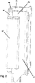
- In the
figures 1 and2 , the wheel block mechanism in tilted condition is displayed, and in thefigures 3 and4 , the wheel block mechanism in ejected condition is displayed. - The mechanism contains a
fixed part 1, where the central part of thefixed part 1 has a cut-out and alsoshoulders 2 at both ends. Theshoulders 2 are equipped withend boards 3, which, in their upper parts, have apin 4 leading inwards. In the cut-out, amovable part 5 is installed that has a shape of rectangle in the cross-section. At the ends of themovable part 5, there are attached flanges 6 that have shape of a square in the cross-section, whereby these flanges 6 fit into theshoulders 2 of thefixed part 1. On theend board 3, thepin 4 is located in the higher position than ending of theshoulder 2. When adjusting the wheel block, themovable part 5 shall be lifted, where height of the stroke is limited by thepin 4 in theend board 3. After this movement, the flange 6 will get above theshoulder 2. Then, themovable part 5 shall be rotated by 90 degrees, and the flange 6 will once again plug into the cut-out. As themovable part 5 has the shape of a rectangle in the cross-section, in one case, the wheel block will be in tilted condition, and in the other case, the wheel block will be in ejected condition.
Claims (1)
- Mechanism for vertical adjustment of the wheel block mainly for railway wagons designed for transportation of cars, characterised in that it contains a fixed part (1), where the central part of the fixed part (1) has a cut-out for the movable part (5) and also shoulders (2) at both ends, the shoulders (2) are equipped with end boards (3), which, in their upper parts, have a pin (4) leading inwards, in the cut-out, a movable part (5) is installed that has a shape of rectangle in the cross-section, at the ends of the movable part (5), there are attached flanges (6) that have shape of a square in the cross-section, whereby these flanges (6) fit into the shoulders (2) of the fixed part (1), on the end board (3), the pin (4) is located in the higher position than ending of the shoulder (2).
Applications Claiming Priority (1)
| Application Number | Priority Date | Filing Date | Title |
|---|---|---|---|
| SK50064-2018U SK8451Y1 (en) | 2018-06-14 | 2018-06-14 | Mechanism for height adjustment of the wheel stop |
Publications (2)
| Publication Number | Publication Date |
|---|---|
| EP3581458A1 true EP3581458A1 (en) | 2019-12-18 |
| EP3581458B1 EP3581458B1 (en) | 2022-05-04 |
Family
ID=62916601
Family Applications (1)
| Application Number | Title | Priority Date | Filing Date |
|---|---|---|---|
| EP18475503.1A Active EP3581458B1 (en) | 2018-06-14 | 2018-07-10 | Mechanism for vertical adjustment of wheel block |
Country Status (3)
| Country | Link |
|---|---|
| EP (1) | EP3581458B1 (en) |
| PL (1) | PL3581458T3 (en) |
| SK (1) | SK8451Y1 (en) |
Citations (8)
| Publication number | Priority date | Publication date | Assignee | Title |
|---|---|---|---|---|
| DE497715C (en) | 1927-08-18 | 1930-05-12 | I G Farbenindustrie Akt Ges | Process for the preparation of halogen substitution products of benzobenzanthrone carboxylic acids |
| FR2376017A1 (en) | 1976-12-29 | 1978-07-28 | Niesky Waggonbau Veb | Adjustable wheel chock for railway car transporter - has chock mounted on struts secured on lateral slotted guide |
| FR2419198A2 (en) | 1976-12-29 | 1979-10-05 | Niesky Waggonbau Veb | Wheel clamp for car transporter rail wagon - has double stays on sliding slotted side rails |
| EP0284532A1 (en) | 1987-03-26 | 1988-09-28 | Lohr Industrie | Self-locking hinged chuck for immobilizing a motor vehicle on a loading ramp |
| EP0497715A1 (en) | 1991-02-01 | 1992-08-05 | Societe De Fabrication Et De Commercialisation - Sofaco- S.A. | Device for wedging of vehicles provided on floors of transport trailers or railway waggons |
| EP1038725A1 (en) * | 1999-03-19 | 2000-09-27 | ROLFO S.p.A. | Pivotable chock for vehicle transporter |
| DE102007004519A1 (en) | 2007-01-24 | 2008-07-31 | Crl Car Rail Logistics Gmbh | Wheel cradle, particularly for auto transport freight wagon, has holding arm, which lies on flat supporting arm and both arms are pivoted by common joint about three hundred and sixty degrees |
| WO2010007245A2 (en) | 2008-07-17 | 2010-01-21 | Lohr Industrie | Chock that can be moved along a section piece and folded by pivoting against this section piece for each tyre of a road-going vehicle carried by a transporter unit |
-
2018
- 2018-06-14 SK SK50064-2018U patent/SK8451Y1/en unknown
- 2018-07-10 EP EP18475503.1A patent/EP3581458B1/en active Active
- 2018-07-10 PL PL18475503.1T patent/PL3581458T3/en unknown
Patent Citations (8)
| Publication number | Priority date | Publication date | Assignee | Title |
|---|---|---|---|---|
| DE497715C (en) | 1927-08-18 | 1930-05-12 | I G Farbenindustrie Akt Ges | Process for the preparation of halogen substitution products of benzobenzanthrone carboxylic acids |
| FR2376017A1 (en) | 1976-12-29 | 1978-07-28 | Niesky Waggonbau Veb | Adjustable wheel chock for railway car transporter - has chock mounted on struts secured on lateral slotted guide |
| FR2419198A2 (en) | 1976-12-29 | 1979-10-05 | Niesky Waggonbau Veb | Wheel clamp for car transporter rail wagon - has double stays on sliding slotted side rails |
| EP0284532A1 (en) | 1987-03-26 | 1988-09-28 | Lohr Industrie | Self-locking hinged chuck for immobilizing a motor vehicle on a loading ramp |
| EP0497715A1 (en) | 1991-02-01 | 1992-08-05 | Societe De Fabrication Et De Commercialisation - Sofaco- S.A. | Device for wedging of vehicles provided on floors of transport trailers or railway waggons |
| EP1038725A1 (en) * | 1999-03-19 | 2000-09-27 | ROLFO S.p.A. | Pivotable chock for vehicle transporter |
| DE102007004519A1 (en) | 2007-01-24 | 2008-07-31 | Crl Car Rail Logistics Gmbh | Wheel cradle, particularly for auto transport freight wagon, has holding arm, which lies on flat supporting arm and both arms are pivoted by common joint about three hundred and sixty degrees |
| WO2010007245A2 (en) | 2008-07-17 | 2010-01-21 | Lohr Industrie | Chock that can be moved along a section piece and folded by pivoting against this section piece for each tyre of a road-going vehicle carried by a transporter unit |
Also Published As
| Publication number | Publication date |
|---|---|
| SK500642018U1 (en) | 2018-12-03 |
| PL3581458T3 (en) | 2022-10-03 |
| SK8451Y1 (en) | 2019-05-06 |
| EP3581458B1 (en) | 2022-05-04 |
Similar Documents
| Publication | Publication Date | Title |
|---|---|---|
| DE69619394T2 (en) | TRANSPORT RACK FOR A JACK BLOW OF A PLANE ENGINE | |
| EP2445789B1 (en) | Locking bar element | |
| DE1265658B (en) | Locking device for pallets | |
| EP2865585B1 (en) | Transport set | |
| DE202011000280U1 (en) | trailer coaches | |
| DE202009004415U1 (en) | Transport equipment for the transport of flat, large-sized objects | |
| EP3581458A1 (en) | Mechanism for vertical adjustment of wheel block | |
| EP3581457A1 (en) | Vertically adjustable wheel block for car-carrying railway wagons | |
| CN105836326B (en) | Container fixed device with self-locking performance | |
| CN204821648U (en) | Push rod travelling bogie | |
| CN110171491A (en) | Automobile-used shelf | |
| CN206749822U (en) | A kind of track top shoulder rail meter | |
| DE202010007494U1 (en) | Unloading device for open transport vehicles | |
| DE102009032905B4 (en) | Supporting trestle for a pocket wagon | |
| DE29716047U1 (en) | Transport system for scooters | |
| CN206327364U (en) | A kind of air suspension chassis railway transportation mooring device | |
| EP3296175B1 (en) | Method for transporting a semitrailer | |
| CN204383474U (en) | A kind of railway freight box wagon car door fastener | |
| DE102010022384A1 (en) | Unloading device for open trolley, particularly for railway car, has tiltable support structure which has platform as base for trolley and carriers at both sides of platform and trolley | |
| CN110171351A (en) | A kind of logistics transportation buffer | |
| CN107600104B (en) | Swing buffer device for transfer platform and use method thereof | |
| EP2771265B1 (en) | Reloading device | |
| SK8591Y1 (en) | Stop for securing large passenger cars with locking in the stowed position | |
| DE193770C (en) | ||
| CN202147670U (en) | manual truck stop |
Legal Events
| Date | Code | Title | Description |
|---|---|---|---|
| PUAI | Public reference made under article 153(3) epc to a published international application that has entered the european phase |
Free format text: ORIGINAL CODE: 0009012 |
|
| STAA | Information on the status of an ep patent application or granted ep patent |
Free format text: STATUS: REQUEST FOR EXAMINATION WAS MADE |
|
| 17P | Request for examination filed |
Effective date: 20180713 |
|
| AK | Designated contracting states |
Kind code of ref document: A1 Designated state(s): AL AT BE BG CH CY CZ DE DK EE ES FI FR GB GR HR HU IE IS IT LI LT LU LV MC MK MT NL NO PL PT RO RS SE SI SK SM TR |
|
| AX | Request for extension of the european patent |
Extension state: BA ME |
|
| GRAP | Despatch of communication of intention to grant a patent |
Free format text: ORIGINAL CODE: EPIDOSNIGR1 |
|
| STAA | Information on the status of an ep patent application or granted ep patent |
Free format text: STATUS: GRANT OF PATENT IS INTENDED |
|
| INTG | Intention to grant announced |
Effective date: 20220125 |
|
| GRAS | Grant fee paid |
Free format text: ORIGINAL CODE: EPIDOSNIGR3 |
|
| GRAA | (expected) grant |
Free format text: ORIGINAL CODE: 0009210 |
|
| STAA | Information on the status of an ep patent application or granted ep patent |
Free format text: STATUS: THE PATENT HAS BEEN GRANTED |
|
| AK | Designated contracting states |
Kind code of ref document: B1 Designated state(s): AL AT BE BG CH CY CZ DE DK EE ES FI FR GB GR HR HU IE IS IT LI LT LU LV MC MK MT NL NO PL PT RO RS SE SI SK SM TR |
|
| REG | Reference to a national code |
Ref country code: GB Ref legal event code: FG4D |
|
| REG | Reference to a national code |
Ref country code: CH Ref legal event code: EP |
|
| REG | Reference to a national code |
Ref country code: AT Ref legal event code: REF Ref document number: 1488776 Country of ref document: AT Kind code of ref document: T Effective date: 20220515 |
|
| REG | Reference to a national code |
Ref country code: IE Ref legal event code: FG4D Ref country code: DE Ref legal event code: R096 Ref document number: 602018034869 Country of ref document: DE |
|
| REG | Reference to a national code |
Ref country code: RO Ref legal event code: EPE |
|
| REG | Reference to a national code |
Ref country code: LT Ref legal event code: MG9D |
|
| REG | Reference to a national code |
Ref country code: NL Ref legal event code: MP Effective date: 20220504 |
|
| REG | Reference to a national code |
Ref country code: SK Ref legal event code: T3 Ref document number: E 40106 Country of ref document: SK |
|
| PG25 | Lapsed in a contracting state [announced via postgrant information from national office to epo] |
Ref country code: SE Free format text: LAPSE BECAUSE OF FAILURE TO SUBMIT A TRANSLATION OF THE DESCRIPTION OR TO PAY THE FEE WITHIN THE PRESCRIBED TIME-LIMIT Effective date: 20220504 Ref country code: PT Free format text: LAPSE BECAUSE OF FAILURE TO SUBMIT A TRANSLATION OF THE DESCRIPTION OR TO PAY THE FEE WITHIN THE PRESCRIBED TIME-LIMIT Effective date: 20220905 Ref country code: NO Free format text: LAPSE BECAUSE OF FAILURE TO SUBMIT A TRANSLATION OF THE DESCRIPTION OR TO PAY THE FEE WITHIN THE PRESCRIBED TIME-LIMIT Effective date: 20220804 Ref country code: NL Free format text: LAPSE BECAUSE OF FAILURE TO SUBMIT A TRANSLATION OF THE DESCRIPTION OR TO PAY THE FEE WITHIN THE PRESCRIBED TIME-LIMIT Effective date: 20220504 Ref country code: LT Free format text: LAPSE BECAUSE OF FAILURE TO SUBMIT A TRANSLATION OF THE DESCRIPTION OR TO PAY THE FEE WITHIN THE PRESCRIBED TIME-LIMIT Effective date: 20220504 Ref country code: HR Free format text: LAPSE BECAUSE OF FAILURE TO SUBMIT A TRANSLATION OF THE DESCRIPTION OR TO PAY THE FEE WITHIN THE PRESCRIBED TIME-LIMIT Effective date: 20220504 Ref country code: GR Free format text: LAPSE BECAUSE OF FAILURE TO SUBMIT A TRANSLATION OF THE DESCRIPTION OR TO PAY THE FEE WITHIN THE PRESCRIBED TIME-LIMIT Effective date: 20220805 Ref country code: FI Free format text: LAPSE BECAUSE OF FAILURE TO SUBMIT A TRANSLATION OF THE DESCRIPTION OR TO PAY THE FEE WITHIN THE PRESCRIBED TIME-LIMIT Effective date: 20220504 Ref country code: ES Free format text: LAPSE BECAUSE OF FAILURE TO SUBMIT A TRANSLATION OF THE DESCRIPTION OR TO PAY THE FEE WITHIN THE PRESCRIBED TIME-LIMIT Effective date: 20220504 Ref country code: BG Free format text: LAPSE BECAUSE OF FAILURE TO SUBMIT A TRANSLATION OF THE DESCRIPTION OR TO PAY THE FEE WITHIN THE PRESCRIBED TIME-LIMIT Effective date: 20220804 |
|
| PG25 | Lapsed in a contracting state [announced via postgrant information from national office to epo] |
Ref country code: RS Free format text: LAPSE BECAUSE OF FAILURE TO SUBMIT A TRANSLATION OF THE DESCRIPTION OR TO PAY THE FEE WITHIN THE PRESCRIBED TIME-LIMIT Effective date: 20220504 Ref country code: LV Free format text: LAPSE BECAUSE OF FAILURE TO SUBMIT A TRANSLATION OF THE DESCRIPTION OR TO PAY THE FEE WITHIN THE PRESCRIBED TIME-LIMIT Effective date: 20220504 Ref country code: IS Free format text: LAPSE BECAUSE OF FAILURE TO SUBMIT A TRANSLATION OF THE DESCRIPTION OR TO PAY THE FEE WITHIN THE PRESCRIBED TIME-LIMIT Effective date: 20220904 |
|
| PG25 | Lapsed in a contracting state [announced via postgrant information from national office to epo] |
Ref country code: SM Free format text: LAPSE BECAUSE OF FAILURE TO SUBMIT A TRANSLATION OF THE DESCRIPTION OR TO PAY THE FEE WITHIN THE PRESCRIBED TIME-LIMIT Effective date: 20220504 Ref country code: EE Free format text: LAPSE BECAUSE OF FAILURE TO SUBMIT A TRANSLATION OF THE DESCRIPTION OR TO PAY THE FEE WITHIN THE PRESCRIBED TIME-LIMIT Effective date: 20220504 Ref country code: DK Free format text: LAPSE BECAUSE OF FAILURE TO SUBMIT A TRANSLATION OF THE DESCRIPTION OR TO PAY THE FEE WITHIN THE PRESCRIBED TIME-LIMIT Effective date: 20220504 |
|
| REG | Reference to a national code |
Ref country code: DE Ref legal event code: R119 Ref document number: 602018034869 Country of ref document: DE |
|
| REG | Reference to a national code |
Ref country code: DE Ref legal event code: R097 Ref document number: 602018034869 Country of ref document: DE |
|
| PG25 | Lapsed in a contracting state [announced via postgrant information from national office to epo] |
Ref country code: MC Free format text: LAPSE BECAUSE OF FAILURE TO SUBMIT A TRANSLATION OF THE DESCRIPTION OR TO PAY THE FEE WITHIN THE PRESCRIBED TIME-LIMIT Effective date: 20220504 |
|
| PLBE | No opposition filed within time limit |
Free format text: ORIGINAL CODE: 0009261 |
|
| STAA | Information on the status of an ep patent application or granted ep patent |
Free format text: STATUS: NO OPPOSITION FILED WITHIN TIME LIMIT |
|
| PG25 | Lapsed in a contracting state [announced via postgrant information from national office to epo] |
Ref country code: AL Free format text: LAPSE BECAUSE OF FAILURE TO SUBMIT A TRANSLATION OF THE DESCRIPTION OR TO PAY THE FEE WITHIN THE PRESCRIBED TIME-LIMIT Effective date: 20220504 |
|
| 26N | No opposition filed |
Effective date: 20230207 |
|
| PG25 | Lapsed in a contracting state [announced via postgrant information from national office to epo] |
Ref country code: LU Free format text: LAPSE BECAUSE OF NON-PAYMENT OF DUE FEES Effective date: 20220710 |
|
| PG25 | Lapsed in a contracting state [announced via postgrant information from national office to epo] |
Ref country code: SI Free format text: LAPSE BECAUSE OF FAILURE TO SUBMIT A TRANSLATION OF THE DESCRIPTION OR TO PAY THE FEE WITHIN THE PRESCRIBED TIME-LIMIT Effective date: 20220504 Ref country code: DE Free format text: LAPSE BECAUSE OF NON-PAYMENT OF DUE FEES Effective date: 20230202 |
|
| REG | Reference to a national code |
Ref country code: AT Ref legal event code: UEP Ref document number: 1488776 Country of ref document: AT Kind code of ref document: T Effective date: 20220504 |
|
| PG25 | Lapsed in a contracting state [announced via postgrant information from national office to epo] |
Ref country code: IE Free format text: LAPSE BECAUSE OF NON-PAYMENT OF DUE FEES Effective date: 20220710 |
|
| PG25 | Lapsed in a contracting state [announced via postgrant information from national office to epo] |
Ref country code: IT Free format text: LAPSE BECAUSE OF FAILURE TO SUBMIT A TRANSLATION OF THE DESCRIPTION OR TO PAY THE FEE WITHIN THE PRESCRIBED TIME-LIMIT Effective date: 20220504 |
|
| PG25 | Lapsed in a contracting state [announced via postgrant information from national office to epo] |
Ref country code: HU Free format text: LAPSE BECAUSE OF FAILURE TO SUBMIT A TRANSLATION OF THE DESCRIPTION OR TO PAY THE FEE WITHIN THE PRESCRIBED TIME-LIMIT; INVALID AB INITIO Effective date: 20180710 |
|
| PG25 | Lapsed in a contracting state [announced via postgrant information from national office to epo] |
Ref country code: MK Free format text: LAPSE BECAUSE OF FAILURE TO SUBMIT A TRANSLATION OF THE DESCRIPTION OR TO PAY THE FEE WITHIN THE PRESCRIBED TIME-LIMIT Effective date: 20220504 Ref country code: CY Free format text: LAPSE BECAUSE OF FAILURE TO SUBMIT A TRANSLATION OF THE DESCRIPTION OR TO PAY THE FEE WITHIN THE PRESCRIBED TIME-LIMIT Effective date: 20220504 |
|
| PG25 | Lapsed in a contracting state [announced via postgrant information from national office to epo] |
Ref country code: MT Free format text: LAPSE BECAUSE OF FAILURE TO SUBMIT A TRANSLATION OF THE DESCRIPTION OR TO PAY THE FEE WITHIN THE PRESCRIBED TIME-LIMIT Effective date: 20220504 |
|
| PG25 | Lapsed in a contracting state [announced via postgrant information from national office to epo] |
Ref country code: BG Free format text: LAPSE BECAUSE OF FAILURE TO SUBMIT A TRANSLATION OF THE DESCRIPTION OR TO PAY THE FEE WITHIN THE PRESCRIBED TIME-LIMIT Effective date: 20220504 |
|
| PG25 | Lapsed in a contracting state [announced via postgrant information from national office to epo] |
Ref country code: BG Free format text: LAPSE BECAUSE OF FAILURE TO SUBMIT A TRANSLATION OF THE DESCRIPTION OR TO PAY THE FEE WITHIN THE PRESCRIBED TIME-LIMIT Effective date: 20220504 |
|
| PGFP | Annual fee paid to national office [announced via postgrant information from national office to epo] |
Ref country code: FR Payment date: 20250624 Year of fee payment: 8 |
|
| PGFP | Annual fee paid to national office [announced via postgrant information from national office to epo] |
Ref country code: PL Payment date: 20250703 Year of fee payment: 8 |
|
| PGFP | Annual fee paid to national office [announced via postgrant information from national office to epo] |
Ref country code: BE Payment date: 20250704 Year of fee payment: 8 Ref country code: GB Payment date: 20250703 Year of fee payment: 8 |
|
| PGFP | Annual fee paid to national office [announced via postgrant information from national office to epo] |
Ref country code: AT Payment date: 20250704 Year of fee payment: 8 |
|
| PGFP | Annual fee paid to national office [announced via postgrant information from national office to epo] |
Ref country code: CH Payment date: 20250801 Year of fee payment: 8 |
|
| PGFP | Annual fee paid to national office [announced via postgrant information from national office to epo] |
Ref country code: CZ Payment date: 20250708 Year of fee payment: 8 |
|
| PGFP | Annual fee paid to national office [announced via postgrant information from national office to epo] |
Ref country code: SK Payment date: 20250715 Year of fee payment: 8 |
|
| PG25 | Lapsed in a contracting state [announced via postgrant information from national office to epo] |
Ref country code: TR Free format text: LAPSE BECAUSE OF FAILURE TO SUBMIT A TRANSLATION OF THE DESCRIPTION OR TO PAY THE FEE WITHIN THE PRESCRIBED TIME-LIMIT Effective date: 20220504 |
|
| PGFP | Annual fee paid to national office [announced via postgrant information from national office to epo] |
Ref country code: RO Payment date: 20251218 Year of fee payment: 8 |