EP3581432A1 - Electric power system of an electric drive vehicle and relative control method - Google Patents
Electric power system of an electric drive vehicle and relative control method Download PDFInfo
- Publication number
- EP3581432A1 EP3581432A1 EP19179443.7A EP19179443A EP3581432A1 EP 3581432 A1 EP3581432 A1 EP 3581432A1 EP 19179443 A EP19179443 A EP 19179443A EP 3581432 A1 EP3581432 A1 EP 3581432A1
- Authority
- EP
- European Patent Office
- Prior art keywords
- electric machine
- electric
- power converter
- electronic
- electronic power
- Prior art date
- Legal status (The legal status is an assumption and is not a legal conclusion. Google has not performed a legal analysis and makes no representation as to the accuracy of the status listed.)
- Granted
Links
Images



Classifications
-
- B—PERFORMING OPERATIONS; TRANSPORTING
- B60—VEHICLES IN GENERAL
- B60L—PROPULSION OF ELECTRICALLY-PROPELLED VEHICLES; SUPPLYING ELECTRIC POWER FOR AUXILIARY EQUIPMENT OF ELECTRICALLY-PROPELLED VEHICLES; ELECTRODYNAMIC BRAKE SYSTEMS FOR VEHICLES IN GENERAL; MAGNETIC SUSPENSION OR LEVITATION FOR VEHICLES; MONITORING OPERATING VARIABLES OF ELECTRICALLY-PROPELLED VEHICLES; ELECTRIC SAFETY DEVICES FOR ELECTRICALLY-PROPELLED VEHICLES
- B60L58/00—Methods or circuit arrangements for monitoring or controlling batteries or fuel cells, specially adapted for electric vehicles
- B60L58/10—Methods or circuit arrangements for monitoring or controlling batteries or fuel cells, specially adapted for electric vehicles for monitoring or controlling batteries
- B60L58/12—Methods or circuit arrangements for monitoring or controlling batteries or fuel cells, specially adapted for electric vehicles for monitoring or controlling batteries responding to state of charge [SoC]
-
- B—PERFORMING OPERATIONS; TRANSPORTING
- B60—VEHICLES IN GENERAL
- B60L—PROPULSION OF ELECTRICALLY-PROPELLED VEHICLES; SUPPLYING ELECTRIC POWER FOR AUXILIARY EQUIPMENT OF ELECTRICALLY-PROPELLED VEHICLES; ELECTRODYNAMIC BRAKE SYSTEMS FOR VEHICLES IN GENERAL; MAGNETIC SUSPENSION OR LEVITATION FOR VEHICLES; MONITORING OPERATING VARIABLES OF ELECTRICALLY-PROPELLED VEHICLES; ELECTRIC SAFETY DEVICES FOR ELECTRICALLY-PROPELLED VEHICLES
- B60L15/00—Methods, circuits, or devices for controlling the traction-motor speed of electrically-propelled vehicles
- B60L15/20—Methods, circuits, or devices for controlling the traction-motor speed of electrically-propelled vehicles for control of the vehicle or its driving motor to achieve a desired performance, e.g. speed, torque, programmed variation of speed
- B60L15/2045—Methods, circuits, or devices for controlling the traction-motor speed of electrically-propelled vehicles for control of the vehicle or its driving motor to achieve a desired performance, e.g. speed, torque, programmed variation of speed for optimising the use of energy
-
- B—PERFORMING OPERATIONS; TRANSPORTING
- B60—VEHICLES IN GENERAL
- B60L—PROPULSION OF ELECTRICALLY-PROPELLED VEHICLES; SUPPLYING ELECTRIC POWER FOR AUXILIARY EQUIPMENT OF ELECTRICALLY-PROPELLED VEHICLES; ELECTRODYNAMIC BRAKE SYSTEMS FOR VEHICLES IN GENERAL; MAGNETIC SUSPENSION OR LEVITATION FOR VEHICLES; MONITORING OPERATING VARIABLES OF ELECTRICALLY-PROPELLED VEHICLES; ELECTRIC SAFETY DEVICES FOR ELECTRICALLY-PROPELLED VEHICLES
- B60L58/00—Methods or circuit arrangements for monitoring or controlling batteries or fuel cells, specially adapted for electric vehicles
- B60L58/10—Methods or circuit arrangements for monitoring or controlling batteries or fuel cells, specially adapted for electric vehicles for monitoring or controlling batteries
-
- B—PERFORMING OPERATIONS; TRANSPORTING
- B60—VEHICLES IN GENERAL
- B60L—PROPULSION OF ELECTRICALLY-PROPELLED VEHICLES; SUPPLYING ELECTRIC POWER FOR AUXILIARY EQUIPMENT OF ELECTRICALLY-PROPELLED VEHICLES; ELECTRODYNAMIC BRAKE SYSTEMS FOR VEHICLES IN GENERAL; MAGNETIC SUSPENSION OR LEVITATION FOR VEHICLES; MONITORING OPERATING VARIABLES OF ELECTRICALLY-PROPELLED VEHICLES; ELECTRIC SAFETY DEVICES FOR ELECTRICALLY-PROPELLED VEHICLES
- B60L58/00—Methods or circuit arrangements for monitoring or controlling batteries or fuel cells, specially adapted for electric vehicles
- B60L58/10—Methods or circuit arrangements for monitoring or controlling batteries or fuel cells, specially adapted for electric vehicles for monitoring or controlling batteries
- B60L58/18—Methods or circuit arrangements for monitoring or controlling batteries or fuel cells, specially adapted for electric vehicles for monitoring or controlling batteries of two or more battery modules
- B60L58/20—Methods or circuit arrangements for monitoring or controlling batteries or fuel cells, specially adapted for electric vehicles for monitoring or controlling batteries of two or more battery modules having different nominal voltages
-
- H—ELECTRICITY
- H02—GENERATION; CONVERSION OR DISTRIBUTION OF ELECTRIC POWER
- H02P—CONTROL OR REGULATION OF ELECTRIC MOTORS, ELECTRIC GENERATORS OR DYNAMO-ELECTRIC CONVERTERS; CONTROLLING TRANSFORMERS, REACTORS OR CHOKE COILS
- H02P27/00—Arrangements or methods for the control of AC motors characterised by the kind of supply voltage
- H02P27/04—Arrangements or methods for the control of AC motors characterised by the kind of supply voltage using variable-frequency supply voltage, e.g. inverter or converter supply voltage
- H02P27/06—Arrangements or methods for the control of AC motors characterised by the kind of supply voltage using variable-frequency supply voltage, e.g. inverter or converter supply voltage using DC to AC converters or inverters
-
- B—PERFORMING OPERATIONS; TRANSPORTING
- B60—VEHICLES IN GENERAL
- B60L—PROPULSION OF ELECTRICALLY-PROPELLED VEHICLES; SUPPLYING ELECTRIC POWER FOR AUXILIARY EQUIPMENT OF ELECTRICALLY-PROPELLED VEHICLES; ELECTRODYNAMIC BRAKE SYSTEMS FOR VEHICLES IN GENERAL; MAGNETIC SUSPENSION OR LEVITATION FOR VEHICLES; MONITORING OPERATING VARIABLES OF ELECTRICALLY-PROPELLED VEHICLES; ELECTRIC SAFETY DEVICES FOR ELECTRICALLY-PROPELLED VEHICLES
- B60L2210/00—Converter types
- B60L2210/40—DC to AC converters
-
- B—PERFORMING OPERATIONS; TRANSPORTING
- B60—VEHICLES IN GENERAL
- B60L—PROPULSION OF ELECTRICALLY-PROPELLED VEHICLES; SUPPLYING ELECTRIC POWER FOR AUXILIARY EQUIPMENT OF ELECTRICALLY-PROPELLED VEHICLES; ELECTRODYNAMIC BRAKE SYSTEMS FOR VEHICLES IN GENERAL; MAGNETIC SUSPENSION OR LEVITATION FOR VEHICLES; MONITORING OPERATING VARIABLES OF ELECTRICALLY-PROPELLED VEHICLES; ELECTRIC SAFETY DEVICES FOR ELECTRICALLY-PROPELLED VEHICLES
- B60L2220/00—Electrical machine types; Structures or applications thereof
- B60L2220/50—Structural details of electrical machines
- B60L2220/56—Structural details of electrical machines with switched windings
-
- B—PERFORMING OPERATIONS; TRANSPORTING
- B60—VEHICLES IN GENERAL
- B60L—PROPULSION OF ELECTRICALLY-PROPELLED VEHICLES; SUPPLYING ELECTRIC POWER FOR AUXILIARY EQUIPMENT OF ELECTRICALLY-PROPELLED VEHICLES; ELECTRODYNAMIC BRAKE SYSTEMS FOR VEHICLES IN GENERAL; MAGNETIC SUSPENSION OR LEVITATION FOR VEHICLES; MONITORING OPERATING VARIABLES OF ELECTRICALLY-PROPELLED VEHICLES; ELECTRIC SAFETY DEVICES FOR ELECTRICALLY-PROPELLED VEHICLES
- B60L2240/00—Control parameters of input or output; Target parameters
- B60L2240/40—Drive Train control parameters
- B60L2240/54—Drive Train control parameters related to batteries
- B60L2240/545—Temperature
-
- B—PERFORMING OPERATIONS; TRANSPORTING
- B60—VEHICLES IN GENERAL
- B60L—PROPULSION OF ELECTRICALLY-PROPELLED VEHICLES; SUPPLYING ELECTRIC POWER FOR AUXILIARY EQUIPMENT OF ELECTRICALLY-PROPELLED VEHICLES; ELECTRODYNAMIC BRAKE SYSTEMS FOR VEHICLES IN GENERAL; MAGNETIC SUSPENSION OR LEVITATION FOR VEHICLES; MONITORING OPERATING VARIABLES OF ELECTRICALLY-PROPELLED VEHICLES; ELECTRIC SAFETY DEVICES FOR ELECTRICALLY-PROPELLED VEHICLES
- B60L50/00—Electric propulsion with power supplied within the vehicle
- B60L50/50—Electric propulsion with power supplied within the vehicle using propulsion power supplied by batteries or fuel cells
- B60L50/51—Electric propulsion with power supplied within the vehicle using propulsion power supplied by batteries or fuel cells characterised by AC-motors
-
- Y—GENERAL TAGGING OF NEW TECHNOLOGICAL DEVELOPMENTS; GENERAL TAGGING OF CROSS-SECTIONAL TECHNOLOGIES SPANNING OVER SEVERAL SECTIONS OF THE IPC; TECHNICAL SUBJECTS COVERED BY FORMER USPC CROSS-REFERENCE ART COLLECTIONS [XRACs] AND DIGESTS
- Y02—TECHNOLOGIES OR APPLICATIONS FOR MITIGATION OR ADAPTATION AGAINST CLIMATE CHANGE
- Y02T—CLIMATE CHANGE MITIGATION TECHNOLOGIES RELATED TO TRANSPORTATION
- Y02T10/00—Road transport of goods or passengers
- Y02T10/60—Other road transportation technologies with climate change mitigation effect
- Y02T10/64—Electric machine technologies in electromobility
-
- Y—GENERAL TAGGING OF NEW TECHNOLOGICAL DEVELOPMENTS; GENERAL TAGGING OF CROSS-SECTIONAL TECHNOLOGIES SPANNING OVER SEVERAL SECTIONS OF THE IPC; TECHNICAL SUBJECTS COVERED BY FORMER USPC CROSS-REFERENCE ART COLLECTIONS [XRACs] AND DIGESTS
- Y02—TECHNOLOGIES OR APPLICATIONS FOR MITIGATION OR ADAPTATION AGAINST CLIMATE CHANGE
- Y02T—CLIMATE CHANGE MITIGATION TECHNOLOGIES RELATED TO TRANSPORTATION
- Y02T10/00—Road transport of goods or passengers
- Y02T10/60—Other road transportation technologies with climate change mitigation effect
- Y02T10/70—Energy storage systems for electromobility, e.g. batteries
-
- Y—GENERAL TAGGING OF NEW TECHNOLOGICAL DEVELOPMENTS; GENERAL TAGGING OF CROSS-SECTIONAL TECHNOLOGIES SPANNING OVER SEVERAL SECTIONS OF THE IPC; TECHNICAL SUBJECTS COVERED BY FORMER USPC CROSS-REFERENCE ART COLLECTIONS [XRACs] AND DIGESTS
- Y02—TECHNOLOGIES OR APPLICATIONS FOR MITIGATION OR ADAPTATION AGAINST CLIMATE CHANGE
- Y02T—CLIMATE CHANGE MITIGATION TECHNOLOGIES RELATED TO TRANSPORTATION
- Y02T10/00—Road transport of goods or passengers
- Y02T10/60—Other road transportation technologies with climate change mitigation effect
- Y02T10/72—Electric energy management in electromobility
Definitions
- the invention relates to an electric power system of an electric drive vehicle and to a corresponding control method.
- the invention finds advantageous application in a road vehicle with hybrid drive, to which explicit reference will be made in the description below without because of this loosing in generality.
- a hybrid vehicle comprises an internal combustion heat engine, which transmits a torque to the drive wheels by means of a drivetrain provided with a transmission, and at least one electric machine, which is electrically connected to a power storage system and is mechanically connected to the drive wheels.
- the electric power system of a hybrid vehicle comprises a storage system provided with a pack of chemical batteries and a two-way electronic DC-AC power converter, which, on the direct current side, is connected to the storage device and, on the alternating current side is connected to the electric machine and fulfils the function of controlling the electric machine.
- the chemical batteries used in current road vehicles with hybrid drive can have a large specific storable electric energy (i.e. per unit of mass and/or volume) and a small specific deliverable electric power (i.e. per unit of mass and/or volume) and, hence, be suited to fulfil the needs of a long stretch of road covered at a moderate speed (and, especially, with limited acceleration/decelerations).
- the chemical batteries used in current road vehicles with hybrid drive can have a small specific storable electric energy (i.e. per unit of mass and/or volume) and a large specific deliverable electric power (i.e. per unit of mass and/or volume) and, hence, be suited to fulfil the needs of a short stretch of road covered at a significant speed (and, especially, with high acceleration/decelerations).
- Italian patent application BO2012A000315 discloses an electric power system of a vehicle with an electric drive obtained by means of at least one first electric machine.
- the electric power system has: a storage system comprising at least two packs of chemical batteries, which are electrically separate from one another; an electronic DC-AC power converter, which exchanges electric energy with the storage system and controls the first electric machine; and a pair of electronic DC-DC power converters, each increasing the voltage and having a low-voltage side, which is electrically connected only to a corresponding pack of chemical batteries, and a high-voltage side, which is connected to the electronic DC-AC power converter in parallel to the high-voltage side of the other electronic DC-DC power converter.
- Patent US8102142B2 describes an electric power system of an electric drive vehicle comprising: a storage system comprising a first pack of chemical batteries and a second pack of chemical batteries, which are electrically separate from one another; a first electronic DC-AC power converter, which has a direct current side connected to the first pack of chemical batteries and an alternating current side connected to the electric machine; and a second electronic DC-AC power converter, which has a direct current side connected to the second pack of chemical batteries and an alternating current side connected to the electric machine, in addition to the first electronic power converter, so that the electric machine can be powered by the first electronic power converter and/or by the second electronic power converter.
- the electric machine can be powered by the sole first pack of chemical batteries, by the sole second pack of chemical batteries or, simultaneously, by both packs of chemical batteries.
- the object of the invention is to provide an electric power system of an electric drive vehicle and a relative control method, said electric power system not being affected by the drawbacks described above and, at the same time, being easy and economic to be manufactured.
- number 1 indicates, as a whole, a road vehicle with hybrid drive, which is provided with two front wheels 2 and two rear drive wheels 3, which receive the torque from a hybrid powertrain system 4.
- the hybrid powertrain system 4 comprises an internal combustion heat engine 5, which is arranged in a front position and is provided with a crankshaft 6, a drivetrain 7, which transmits the torque generated by the internal combustion engine 5 to the rear drive wheels 3, and an electric machine 8, which is mechanically connected to the drivetrain 7 and is reversible (i.e. it can work both as an electric motor, absorbing electric energy and generating a mechanical torque, and as an electric generator, absorbing mechanical energy and generating electric energy).
- the drivetrain 7 comprises a drive shaft 9, which, on one side, is angularly integral to the crankshaft 6 and, on the other side, is mechanically connected to a transmission 10, which is arranged in a rear position and transmits the motion to the rear drive wheels 3 by means of two axle shafts 11, which receive the motion from a differential 12.
- the electric machine 8 is mechanically connected to the transmission 10 and is controlled by a control device 13, which is connected to an electric energy storage system 14 provided with chemical batteries.
- the storage system 14 comprises two distinct packs 15 and 16 of chemical batteries, each consisting of a plurality of chemical batteries connected to one another in series and/or in parallel; each chemical battery comprises respective electrochemical cells, which are suited to turn the chemical energy stored into electric energy and vice versa.
- the chemical batteries of the two packs 15 and 16 of chemical batteries have different electric energy storing and delivering features: in particular, the chemical batteries of the pack 15 of chemical batteries have a greater specific storable electric energy (i.e. per unit of mass and/or volume) and a smaller specific deliverable electric power (i.e. per unit of mass and/or volume) compared to the chemical batteries of the pack 16 of chemical batteries.
- the chemical batteries of the pack 15 of batteries are suited to fulfil the needs of a long stretch of road covered at a moderate speed (and, especially, with limited accelerations/decelerations), as they have the advantage of being capable of providing a large quantity of specific electric energy (i.e. per unit of mass and/or volume), but suffer from the drawback of not being capable of delivering a very large specific electric power (i.e. per unit of mass and/or volume) and, therefore, allow the road vehicle 1 to cover significant distances in electric mode (high range), but do not allow the road vehicle 1 to reach, in electric mode, high dynamic performances.
- the chemical batteries of the pack 16 of batteries are suited to fulfil the needs of a short stretch of road covered at a significant speed (and, especially, with high accelerations/decelerations), as they have the advantage of being capable of delivering a very large specific electric power (i.e. per unit of mass and/or volume), but, on the other hand, are not capable of providing a very large quantity of specific electric energy (i.e. per unit of mass and/or volume) and, therefore, allow the road vehicle 1 to reach, in electric mode, high dynamic performances, but do not allow the road vehicle 1 to cover significant distances in electric mode.
- the proportion between the two packs 15 and 16 of chemical batteries is selected during the designing phase, depending on the desired ratio between range and performances in electric mode.
- the road vehicle 1 is provided with a frame 17 comprising a platform, which makes up a bottom wall of the passenger compartment; in the platform there are two housing accommodating the two packs 15 and 16 of chemical batteries, which rest on the platform itself.
- the road vehicle 1 is provided with an electric power system 18, which comprises the storage system 14 provided with the two packs 15 and 16 of chemical batteries and the control device 13, which, on one side, is connected to the storage system 14 and, on the opposite side, is connected to the electric machine 8 (namely, to the stator windings of the electric machine 8).
- the control device 13 comprises two electronic DC-AC power converters 19 and 20 (i.e.
- each electronic power converter 19 or 20 has a direct current side, which is connected only to a corresponding pack 15 or 16 of chemical batteries (and, hence, is completely isolated form the other electronic power converter 20 or 19 and from the other pack 16 or 15 of chemical batteries), and comprises a three-phase alternating current side, which is connected to same electric machine 8 as the three-phase alternating current side of the other electronic power converter 20 or 19 (namely, the two electronic power converters 19 and 20 are connected in parallel to the terminals of the electric machine 8).
- a control unit 21 which controls the operation of the control device 13 in order to pursue a rotation speed objective (positive for the forward gear and negative for the reverse gear) of the electric machine 8 and a torque objective (positive in case of operation as motor, negative in case of operation as generator) delivered or absorbed by the electric machine 8.
- the electric machine 8 is (always) controlled by one single electronic power converter 19 or 20 at a time, namely one single electronic power converter 19 or 20 at a time applies a three-phase alternating voltage to the terminals of the electric machine 8 (and, therefore, supplies/absorbs a three-phase alternating current flowing through the terminals of the electric machine 8).
- control unit 21 translates the "mechanical" objectives (rotation speed and delivered/absorbed torque of the electric machine 8) into “electric” objectives (among them, an electric power to be supplied/absorbed to/by the electric machine 8) and, based on the "electric” objectives, establishes which one of the two electronic power converters 19 and 20 has to control the electric machine 8 applying an alternating voltage to the terminals of the electric machine 8 (namely, which one of the two electronic power converters 19 and 20 has to power the electric machine 8, which works as a motor, or has to receive electric energy from the electric machine 8, which works as generator).
- control unit 21 cyclically establishes which one of the two electronic power converters 19 and 20 (namely, which one of the two packs 15 and 16 of chemical batteries) has to control the electric machine 8 and, if necessary, reverses (switches) the electronic power converter 19 or 20 (namely, the pack 15 or 16 of chemical batteries) controlling the electric machine 8.
- the selection of which one of the two electronic power converters 19 and 20 (namely, which one of the two packs 15 and 16 of chemical batteries) has to control the electric machine 8 is carried out based on the electric power to be supplied/absorbed to/by the electric machine 8: when the the electric power to be supplied/absorbed to/by the electric machine 8 exceeds a threshold value, the electric machine 8 is controlled by the electronic power converter 20 (namely, by the pack 16 of chemical batteries), whereas, when the electric power to be supplied/absorbed to/by the electric machine 8 is below the threshold value, the electric machine 8 is controlled by the electronic power converter 19, namely by the pack 15 of chemical batteries).
- a hysteresis is applied to the threshold value in order to avoid a too high reversing (switching) frequency when the electric power to be supplied/absorbed to/by the electric machine 8 straddles the threshold value.
- the threshold value can be differentiated between the case of electric power supplied to the electric machine 8 (working as a motor) and the case of electric power absorbed by the electric machine 8 (working as generator).
- the threshold value can be variable depending on the actual temperature of the electronic power converters 19 and 20 (an electronic power converter 20 close to overheating is used less), depending on the actual temperature of the packs 15 and 16 of chemical batteries (a pack 15 or 16 of chemical batteries close to overheating is used less) and/or depending on the actual state of charge of the packs 15 and 16 of chemical batteries (a more exhausted pack 15 or 16 of chemical batteries is used less).
- the reversing (switching) of the electronic power converter 19 or 20 (namely, of the pack 15 or 16 of chemical batteries) controlling the electric machine 8 is exclusively carried out by acting upon the electronics of the electronic power converters 19 and 20 (namely, by turning off the currently operating electronic power converter 19 or 20 and by turning on the other electronic power converter 20 or 19); as a consequence, the reversing (switching) of the electronic power converter 19 or 20 (namely, of the pack 15 and 16 of chemical batteries) controlling the electric machine 8 can take place in a very small amount of time (even below a millisecond) and, hence, can be carried out different (many) timer per second.
- control unit 21 also takes into account the actual state of charge of two packs 15 and 16 of chemical batteries when it has to establish which electronic power converter 19 or 20 (namely, which pack 15 or 16 of chemical batteries) to use to control the electric machine 8; obviously, the control unit 21 will use less frequently (or will not use at all) a pack 15 or 16 of chemical batteries when the pack 15 or 16 of chemical batteries has a state of charge which is significantly lower than the one of the other pack 16 or 15 of chemical batteries.
- control unit 21 could control the two electronic power converters 19 and 20 so as to transfer electric energy between the two packs 15 and 16 of chemical batteries, namely so as to transfer electric energy from the more charged pack 15 or 16 of chemical batteries to the other, more exhausted pack 16 or 15 of chemical batteries (the transfer of electric energy almost always takes place from the pack 15 of chemical batteries to the pack 16 of chemical batteries).
- the two electronic power converters 19 and 20 could be integrated in one single unit, which means that they could both be placed inside a single container and, hence, could also share auxiliary components. Furthermore, it should be pointed out that the electronic power converter 19 must be optimized depending on the features of the pack 15 of chemical batteries (i.e. large quantity of energy and small power), whereas the electronic power converter 20 must be optimized depending on the features of the pack 16 of chemical batteries (i.e. small quantity of energy and great power).
- the electric power system 18 comprises an electronic DC-DC power converter 22 which powers a low-voltage section 23 (typically having a nominal voltage of 12 Volts or 48 Volts), to which all the auxiliary services of the road vehicle 1 are connected (for example, an electric starter motor for the heat engine 5, an electric motor operating a pump of a power steering system, an electric motor operating a circulation pump of a cooling system of the heat engine 5 and/or electric machines 8 and 9, a radio set, a lighting and signalling system).
- the electronic power converter 22 normally is a one-way electronic power converter (i.e. is capable of transferring electric energy only towards the low-voltage section 23 and not vice versa).
- the low-voltage section 23 has no electric energy storage systems provided with chemical batteries (i.e. does not have any chemical battery) and exclusively receives electric energy through the sole electronic power converter 22.
- the electric power system 18 comprises an electric outlet 24, which can be used to charge the storage system 14; when the electric outlet 24 is connected to an external source of electric energy, both electronic power converters 19 and 20 can be used in parallel to simultaneously charge both packs 15 and 16 of batteries or one single electronic power converter 19 or 20 at a time can be used to charge one single pack 15 or 16 of battery at a time.
- the electric outlet 24 is a three-phase outlet, but, alternatively (or in combination), the electric outlet 24 could be a single-phase outlet.
- two switches 25 and 26 are provided, which are interposed between the pack 15 of batteries and the electronic power converter 19 and between the pack 16 of batteries and the electronic power converter 20, respectively; obviously, in this case, the switches 25 and 26 are two-phase switches and are designed to operate with a direct current.
- the two switches 25 and 26 are moved to the alternating current side and are interposed between the electronic power converters 19 and 20 and the electric machine 8, respectively; obviously, in this case, the switches 25 and 26 are three-phase switches and are designed to operate with an alternating current.
- there are two switches 25 and 26 both on the direct current side and on the alternating current side namely, "combining" the embodiment shown in figure 4 with the embodiment shown in figure 5 ).
- the function of the switches 25 and 26 is not that of carrying out the reversing (switching) of the electronic power converter 19 or 20 (namely, of the pack 15 or 16 of chemical batteries) controlling the electric machine 8 (this operation is exclusively carried out by acting upon the electronics of the electronic power converters 19 and 20), but that of isolating the electronic power converter 19 or 20 (namely, the pack 15 or 16 of chemical batteries) which is not being used, as additional safety measure (which protects the electric system 18 in case of errors in the control of the electronic power converters 19 and 20).
- the road vehicle 1 comprises two distinct electric machines 8: in this case, two distinct and independent electronic power converters 19 are provided, which connect the pack 15 of chemical batteries to the two electric machines 8, and two distinct and independent electronic power converters 20 are provided, which connect the pack 16 of chemical batteries to the two electric machines 8 (namely, there are two distinct and independent control devices 13, each connecting the storage system 14 to a corresponding electric machine 8).
- the electric power system 18 described above has numerous advantages.
- the two packs 15 and 16 of chemical batteries are handled in a completely independent manner, since the direct current sides of the electronic power converters 19 and 20 are totally isolated (separated) from the one another.
- the voltage at the terminals of the two packs 15 and 16 of chemical batteries can be different, both in terms of nominal value and in terms of variation during the use.
- This aspect is highly important for, as already mentioned above, the packs 15 and 16 of chemical batteries have very different features and, therefore, in order to properly operate, require different handling strategies.
- the electric power system 18 described above is relatively simple and economic to be manufactured because, despite requiring, for one single electric machine 8, two different electronic power converters 19 and 20 dedicated to the electric machine 8, the two electronic power converters 19 and 20 always operate alternatively and, hence, can be sized for a non-continuous use; as a consequence, cost, weight and size of the electronic power converters 19 and 20 are significantly smaller than twice the cost, weight and size of one single conventional electronic power converter dedicated to the electric machine 8. In other words, doubling the number of electronic power converters dedicated to one single electric machine leads to a reduced increase (far from the double) in the cost, weight and size of the control electronics of the electric machine.
- the management of the switching between the two electronic power converters 19 and 20 is particularly efficient and effective, without causing discontinuities in the torque generated/absorbed by the electric machine 8 and without excessively stressing both the electronic part (namely, the electronic power converters 19 and 20) and the chemical part (namely, the packs 15 and 16 of chemical batteries).
Landscapes
- Engineering & Computer Science (AREA)
- Power Engineering (AREA)
- Transportation (AREA)
- Mechanical Engineering (AREA)
- Life Sciences & Earth Sciences (AREA)
- Sustainable Development (AREA)
- Sustainable Energy (AREA)
- Electric Propulsion And Braking For Vehicles (AREA)
Abstract
Description
- This patent application claims priority from Italian patent application no.
102018000006205 - The invention relates to an electric power system of an electric drive vehicle and to a corresponding control method.
- The invention finds advantageous application in a road vehicle with hybrid drive, to which explicit reference will be made in the description below without because of this loosing in generality.
- A hybrid vehicle comprises an internal combustion heat engine, which transmits a torque to the drive wheels by means of a drivetrain provided with a transmission, and at least one electric machine, which is electrically connected to a power storage system and is mechanically connected to the drive wheels.
- The electric power system of a hybrid vehicle comprises a storage system provided with a pack of chemical batteries and a two-way electronic DC-AC power converter, which, on the direct current side, is connected to the storage device and, on the alternating current side is connected to the electric machine and fulfils the function of controlling the electric machine.
- The chemical batteries used in current road vehicles with hybrid drive can have a large specific storable electric energy (i.e. per unit of mass and/or volume) and a small specific deliverable electric power (i.e. per unit of mass and/or volume) and, hence, be suited to fulfil the needs of a long stretch of road covered at a moderate speed (and, especially, with limited acceleration/decelerations). Alternatively, the chemical batteries used in current road vehicles with hybrid drive can have a small specific storable electric energy (i.e. per unit of mass and/or volume) and a large specific deliverable electric power (i.e. per unit of mass and/or volume) and, hence, be suited to fulfil the needs of a short stretch of road covered at a significant speed (and, especially, with high acceleration/decelerations).
- In order to try and obtain an acceptable compromise between the range needs (which require chemical batteries with a large specific electric energy) and the performance needs (which require chemical batteries with a large specific electric power), manufacturers have tried to produce compromise chemical batteries with intermediate features between the two extremes; however, these compromise chemical batteries turn out to be a "downward" compromise, namely, before a significant reduction of the specific electric energy, they do not feature an equally significant increase in the specific electric power and vice versa.
- In order to try and obtain an acceptable compromise between the range needs (which require chemical batteries with a large specific electric energy) and the performance needs (which require chemical batteries with a large specific electric power), manufacturers have also suggested to insert, in the storage system, both chemical batteries with a large specific electric energy and chemical batteries with a large specific electric power. However, the overall results (in terms of range and performances) and, in particular, the operating life of the chemical batteries turn out to be hardly satisfactory, as the "final result" is in some way smaller than the sum of the single parts.
- Italian patent application
BO2012A000315 BO2012A000315 - Patent
US8102142B2 describes an electric power system of an electric drive vehicle comprising: a storage system comprising a first pack of chemical batteries and a second pack of chemical batteries, which are electrically separate from one another; a first electronic DC-AC power converter, which has a direct current side connected to the first pack of chemical batteries and an alternating current side connected to the electric machine; and a second electronic DC-AC power converter, which has a direct current side connected to the second pack of chemical batteries and an alternating current side connected to the electric machine, in addition to the first electronic power converter, so that the electric machine can be powered by the first electronic power converter and/or by the second electronic power converter. In patentUS8102142B2 , the electric machine can be powered by the sole first pack of chemical batteries, by the sole second pack of chemical batteries or, simultaneously, by both packs of chemical batteries. - The object of the invention is to provide an electric power system of an electric drive vehicle and a relative control method, said electric power system not being affected by the drawbacks described above and, at the same time, being easy and economic to be manufactured.
- According to the invention, there are provided an electric power system of an electric drive vehicle and a relative control method as claimed in the appended claims.
- The appended claims describe preferred embodiments of the invention and form an integral part of the description.
- The invention will now be described with reference to the accompanying drawings, showing a non-limiting embodiment thereof, wherein:
-
figure 1 is a schematic plan view of a road vehicle with hybrid drive; -
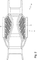
figure 2 is a schematic, plan view of a frame of the road vehicle offigure 1 , highlighting an electric energy storage system; -
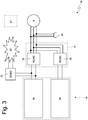
figure 3 is a schematic view of an electric power system of the road vehicle offigure 1 , which is manufactured according to the invention; and -
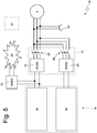
figures 4 ,5 and6 are schematic views of variants of the electric power system offigure 3 . - In
figure 1 ,number 1 indicates, as a whole, a road vehicle with hybrid drive, which is provided with twofront wheels 2 and tworear drive wheels 3, which receive the torque from a hybrid powertrain system 4. - The hybrid powertrain system 4 comprises an internal
combustion heat engine 5, which is arranged in a front position and is provided with a crankshaft 6, adrivetrain 7, which transmits the torque generated by theinternal combustion engine 5 to therear drive wheels 3, and anelectric machine 8, which is mechanically connected to thedrivetrain 7 and is reversible (i.e. it can work both as an electric motor, absorbing electric energy and generating a mechanical torque, and as an electric generator, absorbing mechanical energy and generating electric energy). - The
drivetrain 7 comprises adrive shaft 9, which, on one side, is angularly integral to the crankshaft 6 and, on the other side, is mechanically connected to atransmission 10, which is arranged in a rear position and transmits the motion to therear drive wheels 3 by means of twoaxle shafts 11, which receive the motion from adifferential 12. - The
electric machine 8 is mechanically connected to thetransmission 10 and is controlled by acontrol device 13, which is connected to an electricenergy storage system 14 provided with chemical batteries. - According to
figure 2 , thestorage system 14 comprises twodistinct packs packs pack 15 of chemical batteries have a greater specific storable electric energy (i.e. per unit of mass and/or volume) and a smaller specific deliverable electric power (i.e. per unit of mass and/or volume) compared to the chemical batteries of thepack 16 of chemical batteries. - As a consequence, the chemical batteries of the
pack 15 of batteries are suited to fulfil the needs of a long stretch of road covered at a moderate speed (and, especially, with limited accelerations/decelerations), as they have the advantage of being capable of providing a large quantity of specific electric energy (i.e. per unit of mass and/or volume), but suffer from the drawback of not being capable of delivering a very large specific electric power (i.e. per unit of mass and/or volume) and, therefore, allow theroad vehicle 1 to cover significant distances in electric mode (high range), but do not allow theroad vehicle 1 to reach, in electric mode, high dynamic performances. On the contrary, the chemical batteries of thepack 16 of batteries are suited to fulfil the needs of a short stretch of road covered at a significant speed (and, especially, with high accelerations/decelerations), as they have the advantage of being capable of delivering a very large specific electric power (i.e. per unit of mass and/or volume), but, on the other hand, are not capable of providing a very large quantity of specific electric energy (i.e. per unit of mass and/or volume) and, therefore, allow theroad vehicle 1 to reach, in electric mode, high dynamic performances, but do not allow theroad vehicle 1 to cover significant distances in electric mode. The proportion between the twopacks - Furthermore, the
road vehicle 1 is provided with aframe 17 comprising a platform, which makes up a bottom wall of the passenger compartment; in the platform there are two housing accommodating the twopacks - According to
figure 3 , theroad vehicle 1 is provided with anelectric power system 18, which comprises thestorage system 14 provided with the twopacks control device 13, which, on one side, is connected to thestorage system 14 and, on the opposite side, is connected to the electric machine 8 (namely, to the stator windings of the electric machine 8). Thecontrol device 13 comprises two electronic DC-AC power converters 19 and 20 (i.e. "inverters"), which both control (alternatively) the sameelectric machine 8; namely, eachelectronic power converter corresponding pack electronic power converter other pack electric machine 8 as the three-phase alternating current side of the otherelectronic power converter 20 or 19 (namely, the twoelectronic power converters - A
control unit 21 is provided, which controls the operation of thecontrol device 13 in order to pursue a rotation speed objective (positive for the forward gear and negative for the reverse gear) of theelectric machine 8 and a torque objective (positive in case of operation as motor, negative in case of operation as generator) delivered or absorbed by theelectric machine 8. - In use, the
electric machine 8 is (always) controlled by one singleelectronic power converter electronic power converter control unit 21 translates the "mechanical" objectives (rotation speed and delivered/absorbed torque of the electric machine 8) into "electric" objectives (among them, an electric power to be supplied/absorbed to/by the electric machine 8) and, based on the "electric" objectives, establishes which one of the twoelectronic power converters electric machine 8 applying an alternating voltage to the terminals of the electric machine 8 (namely, which one of the twoelectronic power converters electric machine 8, which works as a motor, or has to receive electric energy from theelectric machine 8, which works as generator). In other words, thecontrol unit 21 cyclically establishes which one of the twoelectronic power converters 19 and 20 (namely, which one of the twopacks electric machine 8 and, if necessary, reverses (switches) theelectronic power converter 19 or 20 (namely, thepack electric machine 8. - Generally speaking, the selection of which one of the two
electronic power converters 19 and 20 (namely, which one of the twopacks electric machine 8 is carried out based on the electric power to be supplied/absorbed to/by the electric machine 8: when the the electric power to be supplied/absorbed to/by theelectric machine 8 exceeds a threshold value, theelectric machine 8 is controlled by the electronic power converter 20 (namely, by thepack 16 of chemical batteries), whereas, when the electric power to be supplied/absorbed to/by theelectric machine 8 is below the threshold value, theelectric machine 8 is controlled by theelectronic power converter 19, namely by thepack 15 of chemical batteries). - Obviously, a hysteresis is applied to the threshold value in order to avoid a too high reversing (switching) frequency when the electric power to be supplied/absorbed to/by the
electric machine 8 straddles the threshold value. The threshold value can be differentiated between the case of electric power supplied to the electric machine 8 (working as a motor) and the case of electric power absorbed by the electric machine 8 (working as generator). Furthermore, the threshold value can be variable depending on the actual temperature of theelectronic power converters 19 and 20 (anelectronic power converter 20 close to overheating is used less), depending on the actual temperature of thepacks pack packs exhausted pack - The reversing (switching) of the
electronic power converter 19 or 20 (namely, of thepack electric machine 8 is exclusively carried out by acting upon the electronics of theelectronic power converters 19 and 20 (namely, by turning off the currently operatingelectronic power converter electronic power converter 20 or 19); as a consequence, the reversing (switching) of theelectronic power converter 19 or 20 (namely, of thepack electric machine 8 can take place in a very small amount of time (even below a millisecond) and, hence, can be carried out different (many) timer per second. - Obviously, the
control unit 21 also takes into account the actual state of charge of twopacks electronic power converter 19 or 20 (namely, which pack 15 or 16 of chemical batteries) to use to control theelectric machine 8; obviously, thecontrol unit 21 will use less frequently (or will not use at all) apack pack other pack - When the
electric machine 8 does not necessarily need to be controlled (because theelectric machine 8 is off or because theroad vehicle 1 is travelling under "cut-off" conditions), thecontrol unit 21 could control the twoelectronic power converters packs charged pack exhausted pack pack 15 of chemical batteries to thepack 16 of chemical batteries). - It should be pointed out that the two
electronic power converters electronic power converter 19 must be optimized depending on the features of thepack 15 of chemical batteries (i.e. large quantity of energy and small power), whereas theelectronic power converter 20 must be optimized depending on the features of thepack 16 of chemical batteries (i.e. small quantity of energy and great power). - The
electric power system 18 comprises an electronic DC-DC power converter 22 which powers a low-voltage section 23 (typically having a nominal voltage of 12 Volts or 48 Volts), to which all the auxiliary services of theroad vehicle 1 are connected (for example, an electric starter motor for theheat engine 5, an electric motor operating a pump of a power steering system, an electric motor operating a circulation pump of a cooling system of theheat engine 5 and/orelectric machines electronic power converter 22 normally is a one-way electronic power converter (i.e. is capable of transferring electric energy only towards the low-voltage section 23 and not vice versa). Generally speaking (though not necessarily), the low-voltage section 23 has no electric energy storage systems provided with chemical batteries (i.e. does not have any chemical battery) and exclusively receives electric energy through the soleelectronic power converter 22. - Furthermore, the
electric power system 18 comprises anelectric outlet 24, which can be used to charge thestorage system 14; when theelectric outlet 24 is connected to an external source of electric energy, bothelectronic power converters packs electronic power converter single pack electric outlet 24 is a three-phase outlet, but, alternatively (or in combination), theelectric outlet 24 could be a single-phase outlet. - In the alternative embodiment shown in
figure 4 , twoswitches pack 15 of batteries and theelectronic power converter 19 and between thepack 16 of batteries and theelectronic power converter 20, respectively; obviously, in this case, theswitches figure 5 , the twoswitches electronic power converters electric machine 8, respectively; obviously, in this case, theswitches figure 6 , there are twoswitches figure 4 with the embodiment shown infigure 5 ). - The function of the
switches electronic power converter 19 or 20 (namely, of thepack electronic power converters 19 and 20), but that of isolating theelectronic power converter 19 or 20 (namely, thepack electric system 18 in case of errors in the control of theelectronic power converters 19 and 20). - According to a different embodiment which is not shown herein (though is perfectly equivalent), the
road vehicle 1 comprises two distinct electric machines 8: in this case, two distinct and independentelectronic power converters 19 are provided, which connect thepack 15 of chemical batteries to the twoelectric machines 8, and two distinct and independentelectronic power converters 20 are provided, which connect thepack 16 of chemical batteries to the two electric machines 8 (namely, there are two distinct andindependent control devices 13, each connecting thestorage system 14 to a corresponding electric machine 8). - According to a different embodiment which is not shown herein (though is perfectly equivalent), there is a larger number of packs of chemical batteries, each electrically connected to its own electronic DC-AC power converter, which has a direct current side, which is only connected to its own pack of chemical batteries, and an alternating current side, which is connected to the
electric machine 8. - The embodiments described herein can be combined with one another, without for this reason going beyond the scope of protection of the invention.
- The
electric power system 18 described above has numerous advantages. - First of all, in the
electric power system 18 described above, the twopacks electronic power converters packs packs - Furthermore, the
electric power system 18 described above is relatively simple and economic to be manufactured because, despite requiring, for one singleelectric machine 8, two differentelectronic power converters electric machine 8, the twoelectronic power converters electronic power converters electric machine 8. In other words, doubling the number of electronic power converters dedicated to one single electric machine leads to a reduced increase (far from the double) in the cost, weight and size of the control electronics of the electric machine. - Finally, in the
electronic power converter 18 described above, the management of the switching between the twoelectronic power converters 19 and 20 (namely, between the twopacks electric machine 8 and without excessively stressing both the electronic part (namely, theelectronic power converters 19 and 20) and the chemical part (namely, thepacks -
- 1
- vehicle
- 2
- front wheels
- 3
- rear wheels
- 4
- powertrain system
- 5
- engine
- 6
- crankshaft
- 7
- drivetrain
- 8
- electric machine
- 9
- drive shaft
- 10
- mechanical transmission
- 11
- axle shafts
- 12
- differential
- 13
- control device
- 14
- storage system
- 15
- pack of energy chemical batteries
- 16
- pack of power chemical batteries
- 17
- frame
- 18
- electric power system
- 19
- electronic power converter
- 20
- electronic power converter
- 21
- control unit
- 22
- electronic power converter
- 23
- low-voltage section
- 24
- electric outlet
- 25
- switch
- 26
- switch
Claims (12)
- An electric power system (18) of a vehicle (1) with an electric drive obtained by means of at least one electric machine (8); the electric power system (18) comprises:a storage system (14) comprising a first pack (15) of chemical batteries and a second pack (16) of chemical batteries, which are electrically separated from one another;a first electronic DC-AC power converter (19), which has a direct current side connected to the first pack (15) of chemical batteries and an alternating current side connected to terminals of the electric machine (8);a second electronic DC-AC power converter (20), which has a direct current side connected to the second pack (15) of chemical batteries and an alternating current side connected to the terminals of the electric machine (8), in addition and in parallel to the first electronic power converter (19), so that the electric machine (8) can be controlled by the first electronic power converter (19) or by the second electronic power converter (20); anda control unit (21), which establishes which one of the two electronic power converters (19, 20) has to control the electric machine (8) and, therefore, establishes when to switch the electronic power converter (19, 20) controlling the electric machine (8);the electric power system (14) is characterized in that:the electric machine (8) is controlled by one single electronic power converter (19, 20) at a time, namely, in any situation, one single electronic power converter (19, 20) at a time applies an alternating voltage to terminals of the electric machine (8) and, therefore, supplies/absorbs an alternating current flowing through the terminals of the electric machine (8);the control unit (21) estimates an electric power to be supplied/absorbed to/by the electric machine (8) and establishes which one of the two electronic power converters (19, 20) has to control the electric machine (8) based on the electric power to be supplied/absorbed to/by the electric machine (8);when the electric power to be supplied/absorbed to/by the electric machine (8) exceeds a threshold value, the electric machine (8) is controlled by the second electronic power converter (20); andwhen the electric power to be supplied/absorbed to/by the electric machine (8) is below a threshold value, the electric machine (8) is controlled by the first electronic power converter (19).
- An electric power system (18) according to claim 1, wherein the control unit (21) applies a hysteresis to the threshold value, so as to avoid an excessive switching frequency when the electric power to be supplied/absorbed to/by the electric machine (8) straddles the threshold value.
- An electric power system (18) according to claim 1 or 2, wherein the threshold value is differentiated between the case of electric power supplied to the electric machine (8) and the case of electric power absorbed by the electric machine (8).
- An electric power system (18) according to claim 1, 2 or 3, wherein the control unit (21) changes the threshold value based on an actual temperature of the electronic power converters (19, 20) and/or based on an actual temperature of the packs (15, 16) of chemical batteries.
- An electric power system (18) according to one of the claim from 1 to 4, wherein the control unit (21) changes the threshold value based on the state of charge of the packs (15, 16) of chemical batteries.
- An electric power system (18) according to one of the claims from 1 to 5, wherein the control unit (21) receives a rotation speed objective for the electric machine (8) and a supplied/absorbed torque objective for the electric machine (8) and determines the electric power to supplied/absorbed to/by the electric machine (8) based on the rotation speed objective for the electric machine (8) and and based on the supplied/absorbed torque objective for the electric machine (8).
- An electric power system (18) according to one of the claims from 1 to 6, wherein the control unit (21) switches the electronic power converter (19, 20) controlling the electric machine (8) by exclusively acting upon the electronics of the electronic power converters (19, 20), namely by turning off the electronic power converter (19, 20) currently working and by turning on the other electronic power converter (20, 19).
- An electric power system (18) according to one of the claims from 1 to 7, wherein, when the electric machine (8) does not necessarily have to be controlled, the control unit (21) can control the two electronic power converters (19, 20) so as to transfer electric energy between the two packs (15, 16) of chemical batteries.
- An electric power system (18) according to one of the claims from 1 to 8 and comprising:a first switch (25), which is interposed between the first pack (15) of batteries and the first electronic power converter (19); anda second switch (26), which is interposed between the second pack (16) of batteries and the second electronic power converter (20).
- An electric power system (18) according to one of the claims from 1 to 9 and comprising:a third switch (25), which is interposed between the first electronic power converter (19) and the electric machine (8); anda fourth switch (26), which is interposed between the second electronic power converter (20) and the electric machine (8).
- An electric power system (18) according to one of the claims from 1 to 10, wherein the first pack (15) of chemical batteries has a greater specific storable electric energy and a smaller specific deliverable electric power compared to the second pack (16) of chemical batteries.
- A method to control an electric power system (18) of a vehicle (1) with an electric drive obtained by means of at least one electric machine (8); the electric power system (18) comprises:a storage system (14) comprising a first pack (15) of chemical batteries and a second pack (16) of chemical batteries, which are electrically separated from one another;a first electronic DC-AC power converter (19), which has a direct current side connected to the first pack (15) of chemical batteries and an alternating current side connected to terminals of the electric machine (8);a second electronic DC-AC power converter (20), which has a direct current side connected to the second pack (15) of chemical batteries and an alternating current side connected to the terminals of the electric machine (8), in addition and in parallel to the first electronic power converter (19), so that the electric machine (8) can be controlled by the first electronic power converter (19) or by the second electronic power converter (20); anda control unit (21), which establishes which one of the two electronic power converters (19, 20) has to control the electric machine (8) and, therefore, establishes when to switch the electronic power converter (19, 20) controlling the electric machine (8);the control method is characterized in that it comprises the steps of:always controlling the electric machine (8) with one single electronic power converter (19, 20) at a time, namely, in any situation, one single electronic power converter (19, 20) at a time applies an alternating voltage to terminals of the electric machine (8) and, therefore, supplies/absorbs an alternating current flowing through the terminals of the electric machine (8).estimating an electric power to be supplied/absorbed to/by the electric machine (8);establishing which one of the two electronic power converters (19, 20) has to control the electric machine (8) based on the electric power to be supplied/absorbed to/by the electric machine (8);controlling the electric machine (8) with the second electronic power converter (20) when the electric power to be supplied/absorbed to/by the electric machine (8) exceeds a threshold value; andcontrolling the electric machine (8) with the first electronic power converter (19) when the electric power to be supplied/absorbed to/by the electric machine (8) is below a threshold value.
Applications Claiming Priority (1)
| Application Number | Priority Date | Filing Date | Title |
|---|---|---|---|
| IT102018000006205A IT201800006205A1 (en) | 2018-06-11 | 2018-06-11 | ELECTRICAL POWER SYSTEM OF A VEHICLE WITH ELECTRIC PROPULSION |
Publications (2)
| Publication Number | Publication Date |
|---|---|
| EP3581432A1 true EP3581432A1 (en) | 2019-12-18 |
| EP3581432B1 EP3581432B1 (en) | 2026-05-06 |
Family
ID=63491906
Family Applications (1)
| Application Number | Title | Priority Date | Filing Date |
|---|---|---|---|
| EP19179443.7A Active EP3581432B1 (en) | 2018-06-11 | 2019-06-11 | Electric power system of an electric drive vehicle and relative control method |
Country Status (3)
| Country | Link |
|---|---|
| US (1) | US10828993B2 (en) |
| EP (1) | EP3581432B1 (en) |
| IT (1) | IT201800006205A1 (en) |
Cited By (1)
| Publication number | Priority date | Publication date | Assignee | Title |
|---|---|---|---|---|
| EP4469299A4 (en) * | 2022-01-26 | 2026-04-01 | Scalvy Inc | ELECTRIC DRIVE SYSTEM FOR AN ELECTRIC DRIVE SYSTEM AND METHOD FOR CONTROLLING IT |
Citations (8)
| Publication number | Priority date | Publication date | Assignee | Title |
|---|---|---|---|---|
| US20090033252A1 (en) * | 2007-07-30 | 2009-02-05 | Gm Global Technology Operations, Inc. | Double ended inverter system for a vehicle having two energy sources that exhibit different operating characteristics |
| US20090033274A1 (en) * | 2007-07-30 | 2009-02-05 | Gm Global Technology Operations, Inc. | System for using a multi-phase motor with a double-ended inverter system |
| EP2034596A1 (en) * | 2006-06-23 | 2009-03-11 | Toyota Jidosha Kabushiki Kaisha | Power supply system and vehicle having the same |
| US20110101915A1 (en) * | 2008-12-09 | 2011-05-05 | Toyota Jidosha Kabushiki Kaisha | Power supply system of vehicle |
| EP2434609A2 (en) * | 2010-09-24 | 2012-03-28 | Lite-On Clean Energy Technology Corp. | Hybrid battery module and battery management method |
| WO2013102673A1 (en) * | 2012-01-06 | 2013-07-11 | Commissariat à l'énergie atomique et aux énergies alternatives | System for supplying an ac load from a plurality of dc voltage sources |
| ITBO20120315A1 (en) | 2012-06-07 | 2013-12-08 | Ferrari Spa | ELECTRICAL POWER PLANT OF A VEHICLE WITH ELECTRIC PROPULSION |
| EP2987674A1 (en) * | 2014-08-19 | 2016-02-24 | General Electric Company | Vehicle propulsion system having an energy storage system and optimized method of controlling operation thereof |
Family Cites Families (6)
| Publication number | Priority date | Publication date | Assignee | Title |
|---|---|---|---|---|
| US7154237B2 (en) * | 2005-01-26 | 2006-12-26 | General Motors Corporation | Unified power control method of double-ended inverter drive systems for hybrid vehicles |
| US8002056B2 (en) * | 2007-07-30 | 2011-08-23 | GM Global Technology Operations LLC | Double-ended inverter system with isolated neutral topology |
| US8026691B2 (en) * | 2007-07-30 | 2011-09-27 | GM Global Technology Operations LLC | Double ended inverter system with a cross-linked ultracapacitor network |
| JP4386138B1 (en) * | 2008-06-27 | 2009-12-16 | トヨタ自動車株式会社 | Control device and control method for hybrid vehicle |
| EP2965935B1 (en) * | 2014-06-17 | 2017-10-04 | FERRARI S.p.A. | Electric power system of a vehicle with electric propulsion |
| JP6187516B2 (en) * | 2015-03-23 | 2017-08-30 | トヨタ自動車株式会社 | Hybrid vehicle |
-
2018
- 2018-06-11 IT IT102018000006205A patent/IT201800006205A1/en unknown
-
2019
- 2019-06-10 US US16/436,529 patent/US10828993B2/en active Active
- 2019-06-11 EP EP19179443.7A patent/EP3581432B1/en active Active
Patent Citations (9)
| Publication number | Priority date | Publication date | Assignee | Title |
|---|---|---|---|---|
| EP2034596A1 (en) * | 2006-06-23 | 2009-03-11 | Toyota Jidosha Kabushiki Kaisha | Power supply system and vehicle having the same |
| US20090033252A1 (en) * | 2007-07-30 | 2009-02-05 | Gm Global Technology Operations, Inc. | Double ended inverter system for a vehicle having two energy sources that exhibit different operating characteristics |
| US20090033274A1 (en) * | 2007-07-30 | 2009-02-05 | Gm Global Technology Operations, Inc. | System for using a multi-phase motor with a double-ended inverter system |
| US8102142B2 (en) | 2007-07-30 | 2012-01-24 | GM Global Technology Operations LLC | Double ended inverter system for a vehicle having two energy sources that exhibit different operating characteristics |
| US20110101915A1 (en) * | 2008-12-09 | 2011-05-05 | Toyota Jidosha Kabushiki Kaisha | Power supply system of vehicle |
| EP2434609A2 (en) * | 2010-09-24 | 2012-03-28 | Lite-On Clean Energy Technology Corp. | Hybrid battery module and battery management method |
| WO2013102673A1 (en) * | 2012-01-06 | 2013-07-11 | Commissariat à l'énergie atomique et aux énergies alternatives | System for supplying an ac load from a plurality of dc voltage sources |
| ITBO20120315A1 (en) | 2012-06-07 | 2013-12-08 | Ferrari Spa | ELECTRICAL POWER PLANT OF A VEHICLE WITH ELECTRIC PROPULSION |
| EP2987674A1 (en) * | 2014-08-19 | 2016-02-24 | General Electric Company | Vehicle propulsion system having an energy storage system and optimized method of controlling operation thereof |
Cited By (1)
| Publication number | Priority date | Publication date | Assignee | Title |
|---|---|---|---|---|
| EP4469299A4 (en) * | 2022-01-26 | 2026-04-01 | Scalvy Inc | ELECTRIC DRIVE SYSTEM FOR AN ELECTRIC DRIVE SYSTEM AND METHOD FOR CONTROLLING IT |
Also Published As
| Publication number | Publication date |
|---|---|
| US10828993B2 (en) | 2020-11-10 |
| US20190375303A1 (en) | 2019-12-12 |
| EP3581432B1 (en) | 2026-05-06 |
| IT201800006205A1 (en) | 2019-12-11 |
Similar Documents
| Publication | Publication Date | Title |
|---|---|---|
| EP3201036B1 (en) | Battery system bi-stable relay control | |
| EP2825794B1 (en) | Vehicle control system | |
| US9538691B2 (en) | Power inverter for a vehicle | |
| EP2965935B1 (en) | Electric power system of a vehicle with electric propulsion | |
| EP3925816B1 (en) | Vehicle drive system with a removable battery | |
| CN106042889B (en) | Power module assembly for vehicle | |
| CN101570148B (en) | Double ended inverter system for a vehicle having two energy sources | |
| JP2019112063A (en) | Vehicle propulsion system with multi-channel dc bus and method of manufacturing the same | |
| EP3730341B1 (en) | Electric system of a road vehicle provided with a dc-dc electronic power converter | |
| US10608222B2 (en) | Integrated modules for battery packs | |
| US11728732B2 (en) | Electrical system having buck converter functionality | |
| US20170033704A1 (en) | Power Inverter Assembly for a Vehicle | |
| US11970072B2 (en) | Vehicle electrical system having a power inverter and electric motor for stepping down voltage | |
| US10199906B2 (en) | Lightweight rotor endplate for electric machine | |
| US10682923B2 (en) | On-board charging system for electric vehicles | |
| US20150283913A1 (en) | Electricity supply system having double power-storage devices of a hybrid or electric motor vehicle | |
| JP2017041973A (en) | Drive apparatus and transport machine | |
| US10919516B2 (en) | Hybrid vehicle | |
| KR20190078633A (en) | Method for operating an on-vehicle network and an on-vehicle network for an electric powered vehicle | |
| GB2598369A (en) | Electrical vehicle circuitry | |
| EP3489069B1 (en) | Electric drive system of a hybrid or electric vehicle | |
| EP3581432B1 (en) | Electric power system of an electric drive vehicle and relative control method | |
| EP2841297B1 (en) | Circuit arrangement and a method for controlling an ac drive system of an electric vehicle | |
| EP4335709B1 (en) | Road vehicle provided with an electronic dc-dc power converter and corresponding control method | |
| JP3400319B2 (en) | Hybrid electric vehicle |
Legal Events
| Date | Code | Title | Description |
|---|---|---|---|
| PUAI | Public reference made under article 153(3) epc to a published international application that has entered the european phase |
Free format text: ORIGINAL CODE: 0009012 |
|
| STAA | Information on the status of an ep patent application or granted ep patent |
Free format text: STATUS: THE APPLICATION HAS BEEN PUBLISHED |
|
| AK | Designated contracting states |
Kind code of ref document: A1 Designated state(s): AL AT BE BG CH CY CZ DE DK EE ES FI FR GB GR HR HU IE IS IT LI LT LU LV MC MK MT NL NO PL PT RO RS SE SI SK SM TR |
|
| AX | Request for extension of the european patent |
Extension state: BA ME |
|
| STAA | Information on the status of an ep patent application or granted ep patent |
Free format text: STATUS: REQUEST FOR EXAMINATION WAS MADE |
|
| 17P | Request for examination filed |
Effective date: 20200617 |
|
| STAA | Information on the status of an ep patent application or granted ep patent |
Free format text: STATUS: EXAMINATION IS IN PROGRESS |
|
| 17Q | First examination report despatched |
Effective date: 20210929 |
|
| P01 | Opt-out of the competence of the unified patent court (upc) registered |
Effective date: 20230525 |
|
| GRAP | Despatch of communication of intention to grant a patent |
Free format text: ORIGINAL CODE: EPIDOSNIGR1 |
|
| STAA | Information on the status of an ep patent application or granted ep patent |
Free format text: STATUS: GRANT OF PATENT IS INTENDED |
|
| INTG | Intention to grant announced |
Effective date: 20251209 |
|
| GRAS | Grant fee paid |
Free format text: ORIGINAL CODE: EPIDOSNIGR3 |
|
| GRAA | (expected) grant |
Free format text: ORIGINAL CODE: 0009210 |
|
| STAA | Information on the status of an ep patent application or granted ep patent |
Free format text: STATUS: THE PATENT HAS BEEN GRANTED |