EP2434609A2 - Hybrid battery module and battery management method - Google Patents
Hybrid battery module and battery management method Download PDFInfo
- Publication number
- EP2434609A2 EP2434609A2 EP11152454A EP11152454A EP2434609A2 EP 2434609 A2 EP2434609 A2 EP 2434609A2 EP 11152454 A EP11152454 A EP 11152454A EP 11152454 A EP11152454 A EP 11152454A EP 2434609 A2 EP2434609 A2 EP 2434609A2
- Authority
- EP
- European Patent Office
- Prior art keywords
- energy storage
- storage unit
- unit
- power
- charging
- Prior art date
- Legal status (The legal status is an assumption and is not a legal conclusion. Google has not performed a legal analysis and makes no representation as to the accuracy of the status listed.)
- Withdrawn
Links
Images


Classifications
-
- H—ELECTRICITY
- H02—GENERATION; CONVERSION OR DISTRIBUTION OF ELECTRIC POWER
- H02J—CIRCUIT ARRANGEMENTS OR SYSTEMS FOR SUPPLYING OR DISTRIBUTING ELECTRIC POWER; SYSTEMS FOR STORING ELECTRIC ENERGY
- H02J7/00—Circuit arrangements for charging or depolarising batteries or for supplying loads from batteries
-
- B—PERFORMING OPERATIONS; TRANSPORTING
- B60—VEHICLES IN GENERAL
- B60L—PROPULSION OF ELECTRICALLY-PROPELLED VEHICLES; SUPPLYING ELECTRIC POWER FOR AUXILIARY EQUIPMENT OF ELECTRICALLY-PROPELLED VEHICLES; ELECTRODYNAMIC BRAKE SYSTEMS FOR VEHICLES IN GENERAL; MAGNETIC SUSPENSION OR LEVITATION FOR VEHICLES; MONITORING OPERATING VARIABLES OF ELECTRICALLY-PROPELLED VEHICLES; ELECTRIC SAFETY DEVICES FOR ELECTRICALLY-PROPELLED VEHICLES
- B60L50/00—Electric propulsion with power supplied within the vehicle
- B60L50/40—Electric propulsion with power supplied within the vehicle using propulsion power supplied by capacitors
-
- B—PERFORMING OPERATIONS; TRANSPORTING
- B60—VEHICLES IN GENERAL
- B60L—PROPULSION OF ELECTRICALLY-PROPELLED VEHICLES; SUPPLYING ELECTRIC POWER FOR AUXILIARY EQUIPMENT OF ELECTRICALLY-PROPELLED VEHICLES; ELECTRODYNAMIC BRAKE SYSTEMS FOR VEHICLES IN GENERAL; MAGNETIC SUSPENSION OR LEVITATION FOR VEHICLES; MONITORING OPERATING VARIABLES OF ELECTRICALLY-PROPELLED VEHICLES; ELECTRIC SAFETY DEVICES FOR ELECTRICALLY-PROPELLED VEHICLES
- B60L58/00—Methods or circuit arrangements for monitoring or controlling batteries or fuel cells, specially adapted for electric vehicles
- B60L58/10—Methods or circuit arrangements for monitoring or controlling batteries or fuel cells, specially adapted for electric vehicles for monitoring or controlling batteries
- B60L58/18—Methods or circuit arrangements for monitoring or controlling batteries or fuel cells, specially adapted for electric vehicles for monitoring or controlling batteries of two or more battery modules
- B60L58/20—Methods or circuit arrangements for monitoring or controlling batteries or fuel cells, specially adapted for electric vehicles for monitoring or controlling batteries of two or more battery modules having different nominal voltages
-
- B—PERFORMING OPERATIONS; TRANSPORTING
- B60—VEHICLES IN GENERAL
- B60L—PROPULSION OF ELECTRICALLY-PROPELLED VEHICLES; SUPPLYING ELECTRIC POWER FOR AUXILIARY EQUIPMENT OF ELECTRICALLY-PROPELLED VEHICLES; ELECTRODYNAMIC BRAKE SYSTEMS FOR VEHICLES IN GENERAL; MAGNETIC SUSPENSION OR LEVITATION FOR VEHICLES; MONITORING OPERATING VARIABLES OF ELECTRICALLY-PROPELLED VEHICLES; ELECTRIC SAFETY DEVICES FOR ELECTRICALLY-PROPELLED VEHICLES
- B60L58/00—Methods or circuit arrangements for monitoring or controlling batteries or fuel cells, specially adapted for electric vehicles
- B60L58/10—Methods or circuit arrangements for monitoring or controlling batteries or fuel cells, specially adapted for electric vehicles for monitoring or controlling batteries
- B60L58/18—Methods or circuit arrangements for monitoring or controlling batteries or fuel cells, specially adapted for electric vehicles for monitoring or controlling batteries of two or more battery modules
- B60L58/21—Methods or circuit arrangements for monitoring or controlling batteries or fuel cells, specially adapted for electric vehicles for monitoring or controlling batteries of two or more battery modules having the same nominal voltage
-
- H—ELECTRICITY
- H01—ELECTRIC ELEMENTS
- H01M—PROCESSES OR MEANS, e.g. BATTERIES, FOR THE DIRECT CONVERSION OF CHEMICAL ENERGY INTO ELECTRICAL ENERGY
- H01M16/00—Structural combinations of different types of electrochemical generators
-
- H—ELECTRICITY
- H02—GENERATION; CONVERSION OR DISTRIBUTION OF ELECTRIC POWER
- H02J—CIRCUIT ARRANGEMENTS OR SYSTEMS FOR SUPPLYING OR DISTRIBUTING ELECTRIC POWER; SYSTEMS FOR STORING ELECTRIC ENERGY
- H02J7/00—Circuit arrangements for charging or depolarising batteries or for supplying loads from batteries
- H02J7/0068—Battery or charger load switching, e.g. concurrent charging and load supply
-
- H—ELECTRICITY
- H02—GENERATION; CONVERSION OR DISTRIBUTION OF ELECTRIC POWER
- H02J—CIRCUIT ARRANGEMENTS OR SYSTEMS FOR SUPPLYING OR DISTRIBUTING ELECTRIC POWER; SYSTEMS FOR STORING ELECTRIC ENERGY
- H02J7/00—Circuit arrangements for charging or depolarising batteries or for supplying loads from batteries
- H02J7/34—Parallel operation in networks using both storage and other dc sources, e.g. providing buffering
- H02J7/342—The other DC source being a battery actively interacting with the first one, i.e. battery to battery charging
-
- H—ELECTRICITY
- H02—GENERATION; CONVERSION OR DISTRIBUTION OF ELECTRIC POWER
- H02J—CIRCUIT ARRANGEMENTS OR SYSTEMS FOR SUPPLYING OR DISTRIBUTING ELECTRIC POWER; SYSTEMS FOR STORING ELECTRIC ENERGY
- H02J2310/00—The network for supplying or distributing electric power characterised by its spatial reach or by the load
- H02J2310/40—The network being an on-board power network, i.e. within a vehicle
- H02J2310/48—The network being an on-board power network, i.e. within a vehicle for electric vehicles [EV] or hybrid vehicles [HEV]
-
- Y—GENERAL TAGGING OF NEW TECHNOLOGICAL DEVELOPMENTS; GENERAL TAGGING OF CROSS-SECTIONAL TECHNOLOGIES SPANNING OVER SEVERAL SECTIONS OF THE IPC; TECHNICAL SUBJECTS COVERED BY FORMER USPC CROSS-REFERENCE ART COLLECTIONS [XRACs] AND DIGESTS
- Y02—TECHNOLOGIES OR APPLICATIONS FOR MITIGATION OR ADAPTATION AGAINST CLIMATE CHANGE
- Y02T—CLIMATE CHANGE MITIGATION TECHNOLOGIES RELATED TO TRANSPORTATION
- Y02T10/00—Road transport of goods or passengers
- Y02T10/60—Other road transportation technologies with climate change mitigation effect
- Y02T10/70—Energy storage systems for electromobility, e.g. batteries
Definitions
- the present invention relates to a battery module; in particular, to a hybrid battery module and a battery management method which are suitable for electric vehicles.
- Electric vehicles have obvious advantages of reducing urban air pollution and have benefits such as quiet, zero pollution emission and without the use of gasoline.
- Electric vehicles require a combination of electrical, mechanical, and battery technologies, wherein battery technology is the most important one.
- battery modules of the electric vehicles may provide the necessary electric power to accelerate the electric vehicles, the battery modules are restricted by the energy density, the power density, also called specific power, and the battery charge and discharge mechanism, etc. Therefore, how to increase the service life of the battery modules for the electric vehicles and reduce the overall volume of the battery modules have became the most important issues which are supposed to be solved during the development of electric vehicles.
- Secondary batteries i.e., rechargeable batteries
- the power type secondary batteries are lithium-iron series batteries or lithium-manganese series batteries, which have higher power densities and may generate large output power instantaneously, suitable for providing instantaneous large electric power required during the electric vehicles startup and acceleration.
- the energy type secondary batteries are lithium-cobalt series batteries with higher energy density which may provide the consistent electric power required for the electric vehicles operating under a steady state, thereby increasing the driving distance of the electric vehicles.
- the present invention provides a hybrid battery module and a method of controlling the same.
- the hybrid battery module may have two different types of energy storage elements, such as two different types of secondary batteries, so as to choose the most suitable power source to provide power in accordance with characteristics of the energy storage elements while the load is under different power requirements. For example, while an electric vehicle is climbing a slope or is accelerating, a power type battery module is used to provide output power; while the electric vehicle is under a normal driving mode, an energy type battery module is applied. The specific method is applied to prevent the damage to the battery and increase the service life of the battery module. Meanwhile, the two types of secondary batteries may charge to each other through a charging path, thereby achieving the effect of transmitting energy to each other. By utilizing the circuit which is designed to allow mutually energy transmission, the hybrid battery module may keep the two types of secondary batteries at the optimum status for providing electric power required by the load.
- the present invention provides a hybrid battery module, which is suitable for supplying power to a load terminal.
- the hybrid battery module comprises a first energy storage unit, a second energy storage unit, a charging unit, and a power supply switching unit.
- the charging unit couples between the first energy storage unit and the second energy storage unit, for selectively providing a charging path between the first energy storage unit and the second energy storage unit, so that the first energy storage unit charges the second energy storage unit or the second energy storage unit charges the first energy storage unit.
- the power supply switching unit couples between the first energy storage unit, the second energy storage unit, and the load terminal, for selectively electrically connecting the load terminal to the first energy storage unit or the second energy storage unit so as to supply power to the load terminal.
- the charging unit comprises a current limit unit and a first switch.
- the current limit unit couples to the first energy storage unit, for limiting the current flowing through of the charging path.
- the first switch couples between the current limit unit and the second energy storage unit.
- the current limit unit is implemented by utilizing a resistor or a bidirectional DC-DC power converter.
- the power supply switching unit comprises a second switch and a third switch.
- the second switch couples between the first energy storage unit and the load terminal.
- the third switch couples between the second energy storage unit and the load terminal.
- the current limit unit and the power supply switching unit are controlled by a battery management circuit.
- the battery management circuit controls the charging unit and the power supply switching unit based on the power statuses of the first energy storage unit and the second energy storage unit, for determining to conduct or cutoff a power supplying path and the charging path.
- the present invention also provides a battery management method, which is suitable for managing a hybrid battery module to supply power to a load terminal.
- the battery management method comprises the following steps: providing a first energy storage unit and a second energy storage unit; selectively providing a charging path between the first energy storage unit and the second energy storage unit, so that the first energy storage unit charges the second energy storage unit or the second energy storage unit charges the first energy storage unit; and selectively electrically connecting the load terminal to the first energy storage unit or the second energy storage unit so as to supply power to the load terminal.
- the hybrid battery module and the battery management method according to the present invention are utilized by providing the conducted charging path between two batteries selectively, so that the two batteries may transfer energy and charge to each other. Furthermore, a current limit unit is applied to overcome the problem of failure transferring energy between the batteries when the internal resistances of the batteries are different.
- FIG. 1 illustrates a schematic diagram of an embodiment of a hybrid battery module according to the present invention
- FIG. 2 illustrates a schematic diagram of the embodiment of the hybrid battery module which utilizes a power type secondary battery and a energy type secondary battery according to the present invention
- FIG. 3 illustrates a schematic diagram of another embodiment of a hybrid battery module according to the present invention.
- FIG. 4 illustrates a schematic diagram of the embodiment of the hybrid battery module which applies a bidirectional DC-DC power converter to replace a current limit unit according to the present invention
- FIG. 5 illustrates a flowchart of yet another embodiment of a battery management method according to the present invention.
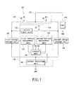
- a hybrid battery module 100 has a load terminal 101 which may connect to the load 105 for supplying power.
- the hybrid battery module 100 comprises a power supply switching unit 110, a charging unit 120, a battery management circuit 130, a first energy storage unit 140, and a second energy storage unit 150.
- the power supply switching unit 110 includes a switch S2 and a switch S3, wherein the switch S2 is coupled between the first energy storage unit 140 and the load terminal 101.
- the switch S3 is coupled between the load terminal 101 and the second energy storage unit 150.
- the charging unit 120 includes a current limit unit 122 and a switch S1, wherein the current limit unit 122 and the switch S1 are coupled in series between the first energy storage unit 140 and the second energy storage unit 150.
- the battery management circuit 130 includes a first battery management unit 131, a second battery management unit 132, a control unit 134, and a current detecting unit 136.
- the control unit 134 is coupled to the first battery management unit 131, the second battery management unit 132, and the current detecting unit 136.
- the first battery management unit 131 is further coupled to the first energy storage unit 140.
- the second battery management unit 132 is further coupled to the second energy storage unit 150.
- the current detecting unit 136 is coupled between the first energy storage unit 140, the second energy storage unit 150, and the ground terminal GND. Moreover, another terminal of the load 105 is coupled to the ground terminal GND.
- the switch S2 and the switch S3 of the power supply switching unit 110 are in response to the outputted control signals P2, P3 from the battery management circuit 130.
- the power supply switching unit 110 may electrically connect the load terminal 101 to the first energy storage unit 140 or the second energy storage unit 150 selectively, for supplying power to the load terminal 101.
- the switch S2 When the switch S2 is conducted, the first energy storage unit 140 may provide power to the load 105 through the load terminal 101; while the switch S3 is conducted, the second energy storage unit 150 may provide power to the load 105 through the load terminal 101.
- the first energy storage unit 140 and the second energy storage unit 150 are secondary batteries.
- the first energy storage unit 140 may be power type secondary batteries, such as lithium-iron or lithium-manganese secondary batteries
- the second energy storage unit 150 may be energy type secondary batteries, such as lithium-cobalt secondary batteries, but are not limited thereto.
- the major difference between the FIG. 1 and FIG. 2 is that the power type secondary battery 240 and the energy type secondary type 250 shown in FIG. 2 are used to replace the first energy storage unit 140 and the second energy storage unit 150 shown in FIG. 1 .
- the power supply switching unit 110 may switch a power supplying path based on the electric power required by the load 105.
- the power supply switching unit 110 may select the first energy storage unit 140 or the second energy storage unit 150 to provide power to the load 105.
- the power supply switching unit 110 may switch the power supplying path to the first energy storage unit 140; while the load 105 requires consistent power supply, the power supply switching unit 110 may switch the power supplying path to the second energy storage unit 150.
- the hybrid battery module 100 may select the most suitable type of energy storage unit to provide power to the load 105 in accordance with the power requirements of the load 105.
- the charging unit 120 is coupled between the first energy storage unit 140 and the second energy storage unit 150, for selectively providing a charging path between the first energy storage unit 140 and the second energy storage unit 150, so that the first energy storage unit 140 charges the second energy storage unit 150 or the second energy storage unit 150 charges the first energy storage unit 140.
- the switch S1 of the charging unit 120 is in response to the outputted control signal P1 from the battery management circuit 130. When the switch S1 is conducted, the charging unit 120 generates a charging path between the first energy storage unit 140 and the second energy storage unit 150, so that the first energy storage unit 140 and the second energy storage unit 150 may charge to each other.
- the second energy storage unit 150 charges the first energy storage unit 140 through the charging path; while the power of the second energy storage unit 150 is low, the first energy storage unit 140 charges the second energy storage unit 150 through the charging path.
- the current limit unit 122 is used to limit the current flowing through the charging path, i.e., restricting the current passing through the current limit unit 122 and the switch S1. Since the internal resistances of the secondary batteries are varied according to the battery type, electric power value, temperature, and battery status, it also requires different current to perform charging.
- the embodiment utilizes the current limit unit 122 to adjust a suitable current so as to transfer energy between two battery packs.
- the current limit unit 122 may be implemented by applying a resistive component, e.g., resistors or variable resistors.
- the resistance value applied by the current limit unit 122 may be determined based on the battery types and battery power statuses of the first energy storage unit 140 and the second energy storage unit 150. In order to achieve the effect of limiting current, it only requires the current limit unit 122 to setup a fixed resistance.
- the current limit unit 122 may be implemented by passive components, e.g., inductors or capacitors, or active components, e.g., bidirectional DC-DC power converters, but are not limited thereto.
- the battery management circuit 130 may be implemented by the first battery management unit 131, the second battery management unit 132, the control unit 134, and the current detecting unit 136.
- the first battery management unit 131 and the second battery management unit 132 are used to monitor the power statuses, e.g., electrical power values, voltage levels, or internal resistances, etc., of the first energy storage unit 140 and the second energy storage unit 150, respectively, but are not limited thereto.
- the current detecting unit 136 is used to detect the current values of the first energy storage unit 140 and the second energy storage unit 150.
- the control unit 134 controls the charging unit 120 and the power supply switch unit 110 based on the power statues and current values of the first energy storage unit 140 and the second energy storage unit 150, for example, controlling the switches S1 ⁇ S3 to determine the ways of charging and discharging.
- the battery management circuit 130 may conduct the switch S 1 to allow the second energy storage unit 150 charge the first energy storage unit 140.
- the first energy storage unit 140 charges to the second energy storage unit 150.
- the battery management circuit 130 turns off (cuts off) the switch S1.
- the first energy storage unit 140 and the second energy storage unit 150 may be recharged by the regenerative electricity from the load 105. For example, as the switch S2 is conducted, the regenerative electricity from the load 105 may charge the first energy storage unit 140; as the switch S3 is conducted, the regenerative electricity from the load 105 may charge the second energy storage unit 150.
- the battery management circuit 130 may control the switches S1 - S3 and adjust the charging and discharging operations of the first energy storage unit 140 and the second energy storage unit 150 according to the power consumption status of the load 105 or the power supplying status.
- states will be described as following: in state (1), when the switches S1 ⁇ S3 are not conducted (turned off), the first energy storage unit 140 and the second energy storage unit 150 do not perform the charging and discharging operations.
- state (2) when only the switch S1 is conducted (turned on), the one with higher power among the first energy storage unit 140 and the second energy storage unit 150 charges to the one with lower power.
- state (3) when only the switch S3 is conducted, the second energy storage unit 150 may discharge to the load 105 or the load 105 charges the second energy storage unit 150.
- the second energy storage unit 150 may discharge to the load 105 or the load 105 may charge to the second energy storage unit 150, meanwhile, the one with higher power among the first energy storage unit 140 and the second energy storage unit 150 charge to the anther one with lower power.
- the first energy storage unit 140 may discharge to the load 195 or the load 105 may charge to the first energy storage unit 140.
- the switches S1, S2 are conducted only, the first energy storage unit 140 may discharge to the load 105 or the load 105 may charge the first energy storage unit 140, meanwhile, the one with higher power among the first energy storage unit 140 and the second energy storage unit 150 may charge to the one with lower power.
- the battery management circuit 130 will not conduct the switches S2 and S3 at any gived time.
- the energy storage unit with higher energy may support the energy storage unit with lower energy to supply power to the load 105, thereby achieving the effect of pushing the load 105.
- the second energy storage unit 150 may not only charge to the first energy storage unit 140 but also supply power to the load 105 through the switch S2 so as to support the first energy storage unit 140 to drive the load 105.
- the first energy storage unit 140 may supply power to the load 105 and charge the second energy storage unit 150 at the same time.
- the energy storage unit with higher power among the first energy storage unit 140 and the second energy storage unit 150 may charge the energy storage unit with lower power value.
- the second energy storage unit 150 has lower power value, the first energy storage unit 140 charges the second energy storage unit 150 and supports the second energy storage unit 150 to drive the load 105.
- the hybrid battery module according to the embodiment of the present invention has recharging function. As the switch S2 is conducted, the regenerative electricity from the load 105 may charge the first energy storage unit 140; as the switch S3 is conducted, the regenerative electricity from the load 105 may charge the second energy storage unit 150.
- the primary function of the battery management circuit 130 is used to monitor the power status of the first energy storage unit 140 and the second energy storage unit 150 and control the switches S1 ⁇ S3, but the configuration is not limited in FIG. 1 .
- the first battery management unit 131 and the second battery management unit 132 may be integrated into a single battery management unit.
- the functions of the first battery management unit 131 and the second battery management unit 132 may be implemented by the control unit 134.
- the configuration of the battery management circuit 130 and the implementation method thereof are illustrated, but are not limited thereto.
- the charging unit 120 has primary function to selectively provide the charging path to the first energy storage unit 140 or the second energy storage unit 150 according to the setup, but the implementation method is not limited thereto in FIG.
- the switch S1 of the charging unit 120 may be replaced by other components, e.g., multiplexers or MOS transistors, etc.
- the charging unit 120 may be implemented by a single component, e.g., a DC-DC power converter. Therefore, the circuit configuration of the charging unit 120 is not limited to be configured by the current limit unit 122 and the switch S1. Moreover, in another embodiment of the present invention, the current limit unit 122 and the switch S 1 may also be integrated into the same circuit.
- FIG. 3 a schematic diagram of another embodiment of the hybrid battery module of the present invention is illustrated.
- the major difference between FIG. 1 and FIG. 3 is a supercapacitor 340 and a secondary battery 350.
- the first energy storage unit 140 and the second energy storage unit 150 as shown in FIG. 1 may be implemented by the supercapacitor or other energy storage component as shown in FIG. 3 .
- the supercapacitor 340 and the secondary battery 350 are used to implement the first energy storage unit 140 and the second energy storage unit 150 as shown in FIG. 1 , respectively.
- the supercapacitor 340 has the effect for storing energy and discharging energy rapidly.
- the supercapacitor 240 is also known as an extra large capacitance capacitor, e.g., an electric double-layer capacitor, but is not limited thereto.
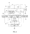
- FIG. 4 illustrates a schematic diagram of the embodiment in accordance with the hybrid battery module which applies a bidirectional DC-DC power converter 422 to replace the current limit unit 122 according to the present invention.
- the major difference between FIG. 1 and FIG. 4 is the bidirectional DC-DC power converter 422 which is coupled between the first energy storage unit 140 and the switch S1, for performing power conversion.
- the bidirectional DC-DC power converter 422 may achieve the effect of power transmission by adjusting the output power according to the states of charge of the first energy storage unit 140 and the second energy storage unit 150, the battery types, and the internal resistances.
- the bidirectional DC-DC power converter utilizes pulse width modulation technique to control and modulate electric power transmission value transmitted from the power type secondary battery to the energy type secondary battery.
- the bidirectional DC-DC power converter controls and modulates electric power transmission value transmitted from the energy type secondary battery to the power type secondary battery.
- the charging unit 120 may be implemented by the bidirectional DC-DC power converter 422, wherein the bidirectional DC-DC power converter 422 may be directly coupled between the first energy storage unit 140 and the second energy storage unit 150 for providing the charging path. Since the current conduction of the bidirectional DC-DC power converter 422 has a direction, e.g., the current passing from the first energy storage unit 140 to the second energy storage unit 150 or passing from the second energy storage unit 150 to the first energy storage unit 140, the bidirectional DC-DC power converter 422 may be used to implement the charging unit 120 directly to provide the charging path and achieve the effect of current limiting. The bidirectional DC-DC power converter may function by shutting down the current transmission so as to stop the energy transmission between the first energy storage unit 140 and the second energy storage unit 150.
- the battery management method which is suitable for supplying power to a load terminal comprises the following steps: providing a first energy storage unit and a second energy storage unit in step S510; determining whether the first energy storage unit and the second energy storage unit require to be charged in step S520, if the power of the first energy storage unit or the second energy storage unit is too low, a charging path may be provided between the first energy storage unit and the second energy storage unit, so that the first energy storage unit charges the second energy storage unit or the second energy storage unit charges the first energy storage unit in step S530.
- step S540 it determines whether the first energy storage unit or the second energy storage unit supplies power. If the first energy storage unit is chosen, the load terminal is electrically connected to the first energy storage unit so as to supply power to the load terminal in step S550; if the second energy storage unit is chosen, the load terminal is electrically connected to the second energy storage unit so as to supply power to the load terminal in step S560.
- step S530 it further restricts the current flowing through the charging path according to the states of charge of the first energy storage unit and the second energy storage unit.
- the aforementioned battery management method is applied on the hybrid battery module which has two different kinds of secondary batteries (the hybrid battery module as shown in FIG. 1 - FIG. 4 ) to control its charging and discharging processes.
- the method provides a charging path between the two energy storage units to allow the energy transferring therebetween while the two energy storage units can also selectively individually connect to the load terminal based on different power requirements. Please refer to the aforementioned descriptions in FIG. 1 ⁇ FIG. 4 for other details.
- the aforementioned embodiment of the hybrid battery module may be applied on electric vehicles.
- the load may be a motor driving system or power system of the electric vehicle, but is not limited thereto.
- the connection relationship for the aforementioned components may be direct, indirect or both direct and indirect electrical connections,, but is not limited thereto, as long as the function of transmitting electrical signals required may be achieved.
- the technical proposal of the aforementioned embodiment may be combined together or be applied individually. The components may be added, removed, adjusted, or replaced based on the functionalities and design requirements, but are not limited thereto.
- the present invention provide a charging path between two different types of energy storage units and utilize the current limit unit to restrict the current flowing through the charging path, so as to achieve the energy transmission between the two energy storage units and to make it suitable for different load requirement. Furthermore, it overcomes a technical problem that the two different types of secondary batteries may not connect electrically directly and may not transmit power to each other due to difference of the internal resistances of the two different of secondary batteries.
Abstract
Description
- The present invention relates to a battery module; in particular, to a hybrid battery module and a battery management method which are suitable for electric vehicles.
- As human awareness of environmental protection and increasing energy conservation, electric vehicles have obvious advantages of reducing urban air pollution and have benefits such as quiet, zero pollution emission and without the use of gasoline. Electric vehicles require a combination of electrical, mechanical, and battery technologies, wherein battery technology is the most important one. Even though the battery modules of the electric vehicles may provide the necessary electric power to accelerate the electric vehicles, the battery modules are restricted by the energy density, the power density, also called specific power, and the battery charge and discharge mechanism, etc. Therefore, how to increase the service life of the battery modules for the electric vehicles and reduce the overall volume of the battery modules have became the most important issues which are supposed to be solved during the development of electric vehicles.
- Since lithium batteries have advantages such as higher discharging rate, shorter charging time, longer cycle time, and better conversion efficiency, it already becomes a vital technique of the next generation of electric vehicles. Secondary batteries, i.e., rechargeable batteries, are divided into power type secondary batteries and energy type secondary batteries based on instantaneous output power. The power type secondary batteries are lithium-iron series batteries or lithium-manganese series batteries, which have higher power densities and may generate large output power instantaneously, suitable for providing instantaneous large electric power required during the electric vehicles startup and acceleration. The energy type secondary batteries are lithium-cobalt series batteries with higher energy density which may provide the consistent electric power required for the electric vehicles operating under a steady state, thereby increasing the driving distance of the electric vehicles.
- Since under operating process the internal resistances and power of the power type secondary batteries and the energy type secondary batteries are different, loads may not recharge these two types of batteries simultaneously. When the power of the power type secondary battery is insufficient, it may not provide large output power instantaneously; while the power of the energy type secondary battery is insufficient, it may not provide consistent power output for the electric vehicles. In order to increase the power and energy provided by the battery module, it's common to use battery modules consisting of a series connected or a parallel connected battery module. The series connected and the parallel connected battery modules use two sets of secondary batteries. In the series connected battery module, the first set of batteries (higher power) provides electricity to the load, and the other set of batteries is used to charge the first set of batteries, without supplying power to the load directly. In the parallel connected battery module, two sets of batteries are selectively switched to supply power to the load, but these two sets of batteries may not charge to each other or provide power to the load at the same time.
- The present invention provides a hybrid battery module and a method of controlling the same. The hybrid battery module may have two different types of energy storage elements, such as two different types of secondary batteries, so as to choose the most suitable power source to provide power in accordance with characteristics of the energy storage elements while the load is under different power requirements. For example, while an electric vehicle is climbing a slope or is accelerating, a power type battery module is used to provide output power; while the electric vehicle is under a normal driving mode, an energy type battery module is applied. The specific method is applied to prevent the damage to the battery and increase the service life of the battery module. Meanwhile, the two types of secondary batteries may charge to each other through a charging path, thereby achieving the effect of transmitting energy to each other. By utilizing the circuit which is designed to allow mutually energy transmission, the hybrid battery module may keep the two types of secondary batteries at the optimum status for providing electric power required by the load.
- The present invention provides a hybrid battery module, which is suitable for supplying power to a load terminal. Therein, the hybrid battery module comprises a first energy storage unit, a second energy storage unit, a charging unit, and a power supply switching unit. The charging unit couples between the first energy storage unit and the second energy storage unit, for selectively providing a charging path between the first energy storage unit and the second energy storage unit, so that the first energy storage unit charges the second energy storage unit or the second energy storage unit charges the first energy storage unit. The power supply switching unit couples between the first energy storage unit, the second energy storage unit, and the load terminal, for selectively electrically connecting the load terminal to the first energy storage unit or the second energy storage unit so as to supply power to the load terminal.
- In an embodiment according to the present invention, the charging unit comprises a current limit unit and a first switch. The current limit unit couples to the first energy storage unit, for limiting the current flowing through of the charging path. The first switch couples between the current limit unit and the second energy storage unit. Therein, the current limit unit is implemented by utilizing a resistor or a bidirectional DC-DC power converter. The power supply switching unit comprises a second switch and a third switch. The second switch couples between the first energy storage unit and the load terminal. The third switch couples between the second energy storage unit and the load terminal.
- Wherein the current limit unit and the power supply switching unit are controlled by a battery management circuit. The battery management circuit controls the charging unit and the power supply switching unit based on the power statuses of the first energy storage unit and the second energy storage unit, for determining to conduct or cutoff a power supplying path and the charging path.
- The present invention also provides a battery management method, which is suitable for managing a hybrid battery module to supply power to a load terminal. The battery management method comprises the following steps: providing a first energy storage unit and a second energy storage unit; selectively providing a charging path between the first energy storage unit and the second energy storage unit, so that the first energy storage unit charges the second energy storage unit or the second energy storage unit charges the first energy storage unit; and selectively electrically connecting the load terminal to the first energy storage unit or the second energy storage unit so as to supply power to the load terminal.
- As per the aforementioned embodiments, the hybrid battery module and the battery management method according to the present invention are utilized by providing the conducted charging path between two batteries selectively, so that the two batteries may transfer energy and charge to each other. Furthermore, a current limit unit is applied to overcome the problem of failure transferring energy between the batteries when the internal resistances of the batteries are different.
- In order to further the understanding regarding the present invention, the following embodiments are provided along with illustrations to facilitate the disclosure of the present invention.
-
FIG. 1 illustrates a schematic diagram of an embodiment of a hybrid battery module according to the present invention; -
FIG. 2 illustrates a schematic diagram of the embodiment of the hybrid battery module which utilizes a power type secondary battery and a energy type secondary battery according to the present invention; -
FIG. 3 illustrates a schematic diagram of another embodiment of a hybrid battery module according to the present invention; -
FIG. 4 illustrates a schematic diagram of the embodiment of the hybrid battery module which applies a bidirectional DC-DC power converter to replace a current limit unit according to the present invention; and -
FIG. 5 illustrates a flowchart of yet another embodiment of a battery management method according to the present invention. - The aforementioned illustrations and following detailed descriptions are exemplary for the purpose of further explaining the scope of the present invention. Other objectives and advantages related to the present invention will be illustrated in the subsequent descriptions and appended drawings.
- (First Embodiment)
- Please refer to
FIG. 1 , in which a schematic diagram of a hybrid battery module in accordance with certain aspects of the present invention is illustrated. Ahybrid battery module 100 has aload terminal 101 which may connect to theload 105 for supplying power. Thehybrid battery module 100 comprises a powersupply switching unit 110, acharging unit 120, abattery management circuit 130, a firstenergy storage unit 140, and a secondenergy storage unit 150. The powersupply switching unit 110 includes a switch S2 and a switch S3, wherein the switch S2 is coupled between the firstenergy storage unit 140 and theload terminal 101. The switch S3 is coupled between theload terminal 101 and the secondenergy storage unit 150. Thecharging unit 120 includes acurrent limit unit 122 and a switch S1, wherein thecurrent limit unit 122 and the switch S1 are coupled in series between the firstenergy storage unit 140 and the secondenergy storage unit 150. Thebattery management circuit 130 includes a firstbattery management unit 131, a secondbattery management unit 132, acontrol unit 134, and acurrent detecting unit 136. Thecontrol unit 134 is coupled to the firstbattery management unit 131, the secondbattery management unit 132, and thecurrent detecting unit 136. The firstbattery management unit 131 is further coupled to the firstenergy storage unit 140. The secondbattery management unit 132 is further coupled to the secondenergy storage unit 150. Thecurrent detecting unit 136 is coupled between the firstenergy storage unit 140, the secondenergy storage unit 150, and the ground terminal GND. Moreover, another terminal of theload 105 is coupled to the ground terminal GND. - The switch S2 and the switch S3 of the power
supply switching unit 110 are in response to the outputted control signals P2, P3 from thebattery management circuit 130. By controlling the switch S2 and the switch S3, the powersupply switching unit 110 may electrically connect theload terminal 101 to the firstenergy storage unit 140 or the secondenergy storage unit 150 selectively, for supplying power to theload terminal 101. When the switch S2 is conducted, the firstenergy storage unit 140 may provide power to theload 105 through theload terminal 101; while the switch S3 is conducted, the secondenergy storage unit 150 may provide power to theload 105 through theload terminal 101. - Please refer to
FIG. 2 as well, in which a schematic diagram of the hybrid battery module in accordance with another embodiment of the present invention is illustrated. In the embodiment, the firstenergy storage unit 140 and the secondenergy storage unit 150 are secondary batteries. The firstenergy storage unit 140 may be power type secondary batteries, such as lithium-iron or lithium-manganese secondary batteries, and the secondenergy storage unit 150 may be energy type secondary batteries, such as lithium-cobalt secondary batteries, but are not limited thereto. The major difference between theFIG. 1 andFIG. 2 is that the power typesecondary battery 240 and the energy typesecondary type 250 shown inFIG. 2 are used to replace the firstenergy storage unit 140 and the secondenergy storage unit 150 shown inFIG. 1 . The powersupply switching unit 110 may switch a power supplying path based on the electric power required by theload 105. The powersupply switching unit 110 may select the firstenergy storage unit 140 or the secondenergy storage unit 150 to provide power to theload 105. For example, when theload 105 requires large electric power instaritaneously, the powersupply switching unit 110 may switch the power supplying path to the firstenergy storage unit 140; while theload 105 requires consistent power supply, the powersupply switching unit 110 may switch the power supplying path to the secondenergy storage unit 150. In other words, thehybrid battery module 100 may select the most suitable type of energy storage unit to provide power to theload 105 in accordance with the power requirements of theload 105. - Please refer to
FIG. 1 , the chargingunit 120 is coupled between the firstenergy storage unit 140 and the secondenergy storage unit 150, for selectively providing a charging path between the firstenergy storage unit 140 and the secondenergy storage unit 150, so that the firstenergy storage unit 140 charges the secondenergy storage unit 150 or the secondenergy storage unit 150 charges the firstenergy storage unit 140. The switch S1 of the chargingunit 120 is in response to the outputted control signal P1 from thebattery management circuit 130. When the switch S1 is conducted, the chargingunit 120 generates a charging path between the firstenergy storage unit 140 and the secondenergy storage unit 150, so that the firstenergy storage unit 140 and the secondenergy storage unit 150 may charge to each other. For example, while the power of the firstenergy storage unit 140 is low, the secondenergy storage unit 150 charges the firstenergy storage unit 140 through the charging path; while the power of the secondenergy storage unit 150 is low, the firstenergy storage unit 140 charges the secondenergy storage unit 150 through the charging path. - While the first
energy storage unit 140 and the secondenergy storage unit 150 are transferring energy to each other, thecurrent limit unit 122 is used to limit the current flowing through the charging path, i.e., restricting the current passing through thecurrent limit unit 122 and the switch S1. Since the internal resistances of the secondary batteries are varied according to the battery type, electric power value, temperature, and battery status, it also requires different current to perform charging. The embodiment utilizes thecurrent limit unit 122 to adjust a suitable current so as to transfer energy between two battery packs. In the embodiment, thecurrent limit unit 122 may be implemented by applying a resistive component, e.g., resistors or variable resistors. It is worth to mention that the resistance value applied by thecurrent limit unit 122 may be determined based on the battery types and battery power statuses of the firstenergy storage unit 140 and the secondenergy storage unit 150. In order to achieve the effect of limiting current, it only requires thecurrent limit unit 122 to setup a fixed resistance. In another embodiment of the present invention, thecurrent limit unit 122 may be implemented by passive components, e.g., inductors or capacitors, or active components, e.g., bidirectional DC-DC power converters, but are not limited thereto. - The
battery management circuit 130 may be implemented by the firstbattery management unit 131, the secondbattery management unit 132, thecontrol unit 134, and the current detectingunit 136. The firstbattery management unit 131 and the secondbattery management unit 132 are used to monitor the power statuses, e.g., electrical power values, voltage levels, or internal resistances, etc., of the firstenergy storage unit 140 and the secondenergy storage unit 150, respectively, but are not limited thereto. The current detectingunit 136 is used to detect the current values of the firstenergy storage unit 140 and the secondenergy storage unit 150. Thecontrol unit 134 controls the chargingunit 120 and the powersupply switch unit 110 based on the power statues and current values of the firstenergy storage unit 140 and the secondenergy storage unit 150, for example, controlling the switches S1 ~ S3 to determine the ways of charging and discharging. - For example, when the power of the first
energy storage unit 140 is low and the power of the secondenergy storage unit 150 is sufficient, thebattery management circuit 130 may conduct theswitch S 1 to allow the secondenergy storage unit 150 charge the firstenergy storage unit 140. On the other hand, while the power of the secondenergy storage unit 150 is low and the power of the firstenergy storage unit 140 is sufficient, the firstenergy storage unit 140 charges to the secondenergy storage unit 150. As the power of both the firstenergy storage unit 140 and the secondenergy storage unit 150 are sufficient, thebattery management circuit 130 turns off (cuts off) the switch S1. Additionally, in the embodiment, the firstenergy storage unit 140 and the secondenergy storage unit 150 may be recharged by the regenerative electricity from theload 105. For example, as the switch S2 is conducted, the regenerative electricity from theload 105 may charge the firstenergy storage unit 140; as the switch S3 is conducted, the regenerative electricity from theload 105 may charge the secondenergy storage unit 150. - The
battery management circuit 130 may control the switches S1 - S3 and adjust the charging and discharging operations of the firstenergy storage unit 140 and the secondenergy storage unit 150 according to the power consumption status of theload 105 or the power supplying status. Several states will be described as following: in state (1), when the switches S1 ~ S3 are not conducted (turned off), the firstenergy storage unit 140 and the secondenergy storage unit 150 do not perform the charging and discharging operations. In state (2), when only the switch S1 is conducted (turned on), the one with higher power among the firstenergy storage unit 140 and the secondenergy storage unit 150 charges to the one with lower power. In state (3), when only the switch S3 is conducted, the secondenergy storage unit 150 may discharge to theload 105 or theload 105 charges the secondenergy storage unit 150. - In state (4), as the switches S1, S3 are conducted only, the second
energy storage unit 150 may discharge to theload 105 or theload 105 may charge to the secondenergy storage unit 150, meanwhile, the one with higher power among the firstenergy storage unit 140 and the secondenergy storage unit 150 charge to the anther one with lower power. In state (5), as theswitch 2 is conducted only, the firstenergy storage unit 140 may discharge to the load 195 or theload 105 may charge to the firstenergy storage unit 140. In state (6), as the switches S1, S2 are conducted only, the firstenergy storage unit 140 may discharge to theload 105 or theload 105 may charge the firstenergy storage unit 140, meanwhile, the one with higher power among the firstenergy storage unit 140 and the secondenergy storage unit 150 may charge to the one with lower power. It is worth to mention that in the embodiment, thebattery management circuit 130 will not conduct the switches S2 and S3 at any gived time. - Additionally, in the process of supplying power, if the
switch S 1 is conducted, the energy storage unit with higher energy may support the energy storage unit with lower energy to supply power to theload 105, thereby achieving the effect of pushing theload 105. For example, as the switches S1, S2 are conducted and the power value of the firstenergy storage unit 140 is lower, the secondenergy storage unit 150 may not only charge to the firstenergy storage unit 140 but also supply power to theload 105 through the switch S2 so as to support the firstenergy storage unit 140 to drive theload 105. - On the other hand, if the power value of the first
energy storage unit 140 is higher, the firstenergy storage unit 140 may supply power to theload 105 and charge the secondenergy storage unit 150 at the same time. According to another aspect of view, as the switches S1 and S3 are conducted, the energy storage unit with higher power among the firstenergy storage unit 140 and the secondenergy storage unit 150 may charge the energy storage unit with lower power value. If the secondenergy storage unit 150 has lower power value, the firstenergy storage unit 140 charges the secondenergy storage unit 150 and supports the secondenergy storage unit 150 to drive theload 105. Moreover, the hybrid battery module according to the embodiment of the present invention has recharging function. As the switch S2 is conducted, the regenerative electricity from theload 105 may charge the firstenergy storage unit 140; as the switch S3 is conducted, the regenerative electricity from theload 105 may charge the secondenergy storage unit 150. - In addition, in the embodiment, the primary function of the
battery management circuit 130 is used to monitor the power status of the firstenergy storage unit 140 and the secondenergy storage unit 150 and control the switches S1 ~ S3, but the configuration is not limited inFIG. 1 . For example, the firstbattery management unit 131 and the secondbattery management unit 132 may be integrated into a single battery management unit. The functions of the firstbattery management unit 131 and the secondbattery management unit 132 may be implemented by thecontrol unit 134. The configuration of thebattery management circuit 130 and the implementation method thereof are illustrated, but are not limited thereto. It is worth to mention that the chargingunit 120 has primary function to selectively provide the charging path to the firstenergy storage unit 140 or the secondenergy storage unit 150 according to the setup, but the implementation method is not limited thereto inFIG. 1 . The switch S1 of the chargingunit 120 may be replaced by other components, e.g., multiplexers or MOS transistors, etc. The chargingunit 120 may be implemented by a single component, e.g., a DC-DC power converter. Therefore, the circuit configuration of the chargingunit 120 is not limited to be configured by thecurrent limit unit 122 and the switch S1. Moreover, in another embodiment of the present invention, thecurrent limit unit 122 and theswitch S 1 may also be integrated into the same circuit. - (Second Embodiment)
- Please refer to
FIG. 3 , in which a schematic diagram of another embodiment of the hybrid battery module of the present invention is illustrated. The major difference betweenFIG. 1 andFIG. 3 is asupercapacitor 340 and asecondary battery 350. The firstenergy storage unit 140 and the secondenergy storage unit 150 as shown inFIG. 1 may be implemented by the supercapacitor or other energy storage component as shown inFIG. 3 . Thesupercapacitor 340 and thesecondary battery 350 are used to implement the firstenergy storage unit 140 and the secondenergy storage unit 150 as shown inFIG. 1 , respectively. Thesupercapacitor 340 has the effect for storing energy and discharging energy rapidly. Therefore, as long as the capacitance value of thesupercapacitor 240 is large enough, a large power output is generated to drive theload 105. Thesupercapacitor 240 is also known as an extra large capacitance capacitor, e.g., an electric double-layer capacitor, but is not limited thereto. - (third embodiment)
- The
current limit unit 122 shown inFIG. 1 may be replaced by a bidirectional DC-DC power converter as shown inFIG. 4. FIG. 4 illustrates a schematic diagram of the embodiment in accordance with the hybrid battery module which applies a bidirectional DC-DC power converter 422 to replace thecurrent limit unit 122 according to the present invention. The major difference betweenFIG. 1 andFIG. 4 is the bidirectional DC-DC power converter 422 which is coupled between the firstenergy storage unit 140 and the switch S1, for performing power conversion. The bidirectional DC-DC power converter 422 may achieve the effect of power transmission by adjusting the output power according to the states of charge of the firstenergy storage unit 140 and the secondenergy storage unit 150, the battery types, and the internal resistances. For example, as the power type secondary battery charges the energy type secondary battery, the bidirectional DC-DC power converter utilizes pulse width modulation technique to control and modulate electric power transmission value transmitted from the power type secondary battery to the energy type secondary battery. On the other hand, the bidirectional DC-DC power converter controls and modulates electric power transmission value transmitted from the energy type secondary battery to the power type secondary battery. - Moreover, Since the bidirectional DC-
DC power converter 422 has switching function as well, in another embodiment of the present invention, the chargingunit 120 may be implemented by the bidirectional DC-DC power converter 422, wherein the bidirectional DC-DC power converter 422 may be directly coupled between the firstenergy storage unit 140 and the secondenergy storage unit 150 for providing the charging path. Since the current conduction of the bidirectional DC-DC power converter 422 has a direction, e.g., the current passing from the firstenergy storage unit 140 to the secondenergy storage unit 150 or passing from the secondenergy storage unit 150 to the firstenergy storage unit 140, the bidirectional DC-DC power converter 422 may be used to implement thecharging unit 120 directly to provide the charging path and achieve the effect of current limiting. The bidirectional DC-DC power converter may function by shutting down the current transmission so as to stop the energy transmission between the firstenergy storage unit 140 and the secondenergy storage unit 150. - From the aforementioned embodiments, it may also conclude a battery management method. Please refer to
FIG. 5 , in which a flowchart of the battery management method according to the present invention is illustrated. The battery management method, which is suitable for supplying power to a load terminal comprises the following steps: providing a first energy storage unit and a second energy storage unit in step S510; determining whether the first energy storage unit and the second energy storage unit require to be charged in step S520, if the power of the first energy storage unit or the second energy storage unit is too low, a charging path may be provided between the first energy storage unit and the second energy storage unit, so that the first energy storage unit charges the second energy storage unit or the second energy storage unit charges the first energy storage unit in step S530. By utilizing the aforementioned steps of S520 and S530, it may selectively provide the charging path between the first energy storage unit and the second energy storage unit, so that the energy of the two energy storage units may transfer to each other. Base on the power requirement of the load, in step S540, it determines whether the first energy storage unit or the second energy storage unit supplies power. If the first energy storage unit is chosen, the load terminal is electrically connected to the first energy storage unit so as to supply power to the load terminal in step S550; if the second energy storage unit is chosen, the load terminal is electrically connected to the second energy storage unit so as to supply power to the load terminal in step S560. Herein, in step S530, it further restricts the current flowing through the charging path according to the states of charge of the first energy storage unit and the second energy storage unit. - The aforementioned battery management method is applied on the hybrid battery module which has two different kinds of secondary batteries (the hybrid battery module as shown in
FIG. 1 - FIG. 4 ) to control its charging and discharging processes. The method provides a charging path between the two energy storage units to allow the energy transferring therebetween while the two energy storage units can also selectively individually connect to the load terminal based on different power requirements. Please refer to the aforementioned descriptions inFIG. 1 ~ FIG. 4 for other details. - It is worth to mention that the aforementioned embodiment of the hybrid battery module may be applied on electric vehicles. Herein, the load may be a motor driving system or power system of the electric vehicle, but is not limited thereto. Additionally, the connection relationship for the aforementioned components may be direct, indirect or both direct and indirect electrical connections,, but is not limited thereto, as long as the function of transmitting electrical signals required may be achieved. The technical proposal of the aforementioned embodiment may be combined together or be applied individually. The components may be added, removed, adjusted, or replaced based on the functionalities and design requirements, but are not limited thereto.
- As per the aforementioned descriptions, the present invention provide a charging path between two different types of energy storage units and utilize the current limit unit to restrict the current flowing through the charging path, so as to achieve the energy transmission between the two energy storage units and to make it suitable for different load requirement. Furthermore, it overcomes a technical problem that the two different types of secondary batteries may not connect electrically directly and may not transmit power to each other due to difference of the internal resistances of the two different of secondary batteries.
- The descriptions illustrated supra set forth simply the preferred embodiments of the present invention; however, the characteristics of the present invention are by no means restricted thereto. All changes, alternations, or modifications conveniently considered by those skilled in the art are deemed to be encompassed within the scope of the present invention delineated by the following claims.
Claims (19)
- A hybrid battery module for supplying energy to a load terminal, comprising:a first energy storage unit;a second energy storage unit;a charging unit coupled between the first energy storage unit and the second energy storage unit for selectively providing a charging path between the first energy storage unit and the second energy storage unit, so that the first energy storage unit charges the second energy storage unit or the second energy storage unit charges the first energy storage unit; anda power supply switching unit coupled between the first energy storage unit, the second energy storage unit, and the load terminal for selectively electrically connecting the load terminal to the first energy storage unit or the second energy storage unit so as to supply power to the load terminal.
- The hybrid battery module according to claim 1, wherein a power density of the first energy storage unit is greater than that of the second energy storage unit and an energy density of the second energy storage unit is greater than that of the first energy storage unit.
- The hybrid battery module according to claim 1, wherein the first energy storage unit is a power type secondary battery and the second energy storage unit is an energy type secondary battery.
- The hybrid battery module according to claim 1, wherein the first energy storage unit is a supercapacitor and the second energy storage unit is a secondary battery.
- The hybrid battery module according to claim 1, wherein charging unit restricts a current flowing through the charging path based on power statuses of the first energy storage unit and the second energy storage unit.
- The hybrid battery module according to claim 5, wherein the charging unit comprises:a current limit unit coupled to the first energy storage unit for limiting the current flowing through the charging path; anda first switch coupled between the current limit unit and the second energy storage unit.
- The hybrid battery module according to claim 6, wherein the current limit unit comprises:a impedance component coupled between the first energy storage unit and the first switch.
- The hybrid battery module according to claim 1, wherein the charging unit comprises:a bidirectional DC-DC power converter coupled to the first energy storage unit; anda first switch coupled between the bidirectional DC-DC power converter and the second energy storage unit.
- The hybrid battery module according to claim 1, wherein the power supply switching unit comprises:a second switch coupled between the first energy storage unit and the load terminal; anda third switch coupled between the load terminal and the second energy storage unit.
- The hybrid battery module according to claim 1, wherein the power supply switching unit comprises:a bidirectional DC-DC power converter coupled between the first energy storage unit and the second energy storage unit for selectively providing the charging path between the first energy storage unit and the second energy storage unit.
- The hybrid battery module according to claim 1, wherein the charging unit comprises:a current limit unit coupled to the first energy storage unit for restricting a current flowing through the charging path; anda first switch coupled between the current limit unit and the second energy storage unit;wherein the power supply switching unit comprises:a second switch coupled between the first energy storage unit and the load terminal; anda third switch coupled between the load terminal and the second energy storage unit.
- The hybrid battery module according to claim 1 further comprising:a battery management circuit coupled to the first energy storage unit, the second energy storage unit, the charging unit, and the power supply switching unit for controlling the charging unit and the power supply switching unit according to power statuses of the first energy storage unit and the second energy storage unit.
- The hybrid battery module according to claim 12, wherein the battery management unit comprises:a first battery management unit coupled to the first energy storage unit for monitoring the power status of the first energy storage unit;a second battery management unit coupled to the second energy storage unit for monitoring the power status of the second energy storage unit;a current detecting unit coupled to the first energy storage unit and the second energy storage unit for detecting current values of the first energy storage unit and the second energy storage unit; anda control unit coupled to the first battery management unit, the second battery management unit, the current detecting unit, the charging unit, and the power supply switching unit for controlling the charging unit and the power supply switching unit.
- A battery management method suitable for managing a hybrid battery module to supply power to a load terminal, comprising:providing a first energy storage unit and a second energy storage unit;selectively providing a charging path between the first energy storage unit and the second energy storage unit, so that the first energy storage unit charges the second energy storage unit or the second energy storage unit charges the first energy storage unit; andselectively electrically connecting the load terminal to the first energy storage unit or the second energy storage unit so as to supply power to the load terminal.
- The battery management method according to claim 14 further comprising:restricting a current flowing through the charging path based on power status of the first energy storage unit and the second energy storage unit.
- The battery management method according to claim 14 further comprising:controlling the charging unit and the power supply switching unit based on power status of the first energy storage unit and the second energy storage unit.
- The battery management method according to claim 14, wherein a power density of the first energy storage unit is greater than that of the second energy storage unit and an energy density of the second energy storage unit is greater than that of the first energy storage unit.
- The battery management method according to claim 14, wherein the first energy storage unit is a power type secondary battery and the second energy storage unit is an energy type secondary battery.
- The battery management method according to claim 14, wherein the first energy storage unit is a supercapacitor and the second energy storage unit is a secondary battery.
Applications Claiming Priority (1)
| Application Number | Priority Date | Filing Date | Title |
|---|---|---|---|
| TW099132430A TW201214919A (en) | 2010-09-24 | 2010-09-24 | Hybrid battery module and battery management method |
Publications (2)
| Publication Number | Publication Date |
|---|---|
| EP2434609A2 true EP2434609A2 (en) | 2012-03-28 |
| EP2434609A3 EP2434609A3 (en) | 2017-10-11 |
Family
ID=43629178
Family Applications (1)
| Application Number | Title | Priority Date | Filing Date |
|---|---|---|---|
| EP11152454.2A Withdrawn EP2434609A3 (en) | 2010-09-24 | 2011-01-28 | Hybrid battery module and battery management method |
Country Status (5)
| Country | Link |
|---|---|
| US (1) | US20120074894A1 (en) |
| EP (1) | EP2434609A3 (en) |
| JP (1) | JP2012070609A (en) |
| CN (1) | CN102447301A (en) |
| TW (1) | TW201214919A (en) |
Cited By (10)
| Publication number | Priority date | Publication date | Assignee | Title |
|---|---|---|---|---|
| CN105024420A (en) * | 2014-04-28 | 2015-11-04 | 三星电子株式会社 | Battery control apparatus, battery pack and battery control method |
| WO2016087632A1 (en) * | 2014-12-05 | 2016-06-09 | Valeo Equipements Electriques Moteur | Improved direct-current converter and power supply device |
| US9457666B2 (en) | 2012-03-30 | 2016-10-04 | Elwha Llc | Method and apparatus for supplying auxiliary electrical power to an electric or hybrid vehicle |
| WO2016178185A1 (en) * | 2015-05-06 | 2016-11-10 | Suren Martirosyan | Battery management system for bi-cathode discharging-cells |
| EP3226395A1 (en) * | 2016-03-31 | 2017-10-04 | Valeo Interior Controls Co., Ltd. | Pre-charging circuit, dc-dc converter and hybrid vehicle |
| CN107546827A (en) * | 2017-08-16 | 2018-01-05 | 湖北华中光电科技有限公司 | A kind of power compensation circuit of vehicle power |
| GB2552483A (en) * | 2016-07-25 | 2018-01-31 | Jaguar Land Rover Ltd | Battery management apparatus and method |
| US10199694B2 (en) | 2013-03-01 | 2019-02-05 | Semiconductor Energy Laboratory Co., Ltd. | Power storage system |
| WO2019053403A3 (en) * | 2017-09-15 | 2019-04-25 | Dyson Technology Limited | Energy storage system |
| EP3581432A1 (en) * | 2018-06-11 | 2019-12-18 | FERRARI S.p.A. | Electric power system of an electric drive vehicle and relative control method |
Families Citing this family (61)
| Publication number | Priority date | Publication date | Assignee | Title |
|---|---|---|---|---|
| TWM421641U (en) * | 2011-08-09 | 2012-01-21 | ming-xiang Ye | Back discharging protection sleeve for handset device |
| JP5772476B2 (en) * | 2011-10-12 | 2015-09-02 | トヨタ自動車株式会社 | Electric car |
| FR2988926B1 (en) * | 2012-03-28 | 2014-03-28 | Valeo Equip Electr Moteur | METHOD AND SYSTEM FOR ELECTRICALLY POWERING A HYBRID MOTOR VEHICLE WITH DOUBLE STORAGE ELECTRICAL ENERGY STORES |
| TWI550995B (en) * | 2012-04-26 | 2016-09-21 | 華夏學校財團法人華夏科技大學 | Eletronic device utilizing super capacitor to act as auxiliary power supply and charge method thereof |
| JP2014017074A (en) * | 2012-07-06 | 2014-01-30 | Toyota Motor Corp | Device for controlling precipitation and dissolution of reaction involving substance in secondary battery |
| JP2014023221A (en) * | 2012-07-13 | 2014-02-03 | Toshiba Corp | Secondary battery system |
| CN103568854A (en) * | 2012-07-25 | 2014-02-12 | 光阳工业股份有限公司 | Electric car battery parallel-connection control system |
| US9172266B2 (en) * | 2013-02-19 | 2015-10-27 | Gojo Industries, Inc. | Power systems for touch free dispensers and refill units containing a power source |
| CN102891522B (en) * | 2012-09-28 | 2015-06-03 | 郑州宇通客车股份有限公司 | Dual-energy-storage device with vehicle-mounted charging function |
| CN102891513A (en) * | 2012-10-10 | 2013-01-23 | 上海中科深江电动车辆有限公司 | Energy use control system for battery pack |
| US20140181540A1 (en) * | 2012-12-26 | 2014-06-26 | Nvidia Corporation | Hybrid battery pack |
| KR20150108825A (en) | 2013-01-21 | 2015-09-30 | 가부시키가이샤 한도오따이 에네루기 켄큐쇼 | Secondary battery, secondary battery module, method for charging the secondary battery and the secondary battery module, method for discharging the secondary battery and the secondary battery module, method for operating the secondary battery and the secondary battery module, power storage system, and method for operating the power storage system |
| JP2014241224A (en) * | 2013-06-11 | 2014-12-25 | イーメックス株式会社 | Hybrid battery system |
| DE102013106777A1 (en) * | 2013-06-28 | 2014-12-31 | Dr. Ing. H.C. F. Porsche Aktiengesellschaft | Board grid stabilization |
| CN104641533B (en) * | 2013-07-30 | 2019-02-26 | 株式会社Lg化学 | Device and method for controlling battery |
| CN103441561A (en) * | 2013-08-15 | 2013-12-11 | 重庆长安汽车股份有限公司 | Automobile secondary energy storing device based on super-capacitor and control method |
| FR3011398B1 (en) * | 2013-09-30 | 2018-02-02 | Astrium | METHOD FOR OPTIMIZING AN ELECTRIC POWER ARCHITECTURE OF A LOAD |
| CN104659921B (en) * | 2013-11-26 | 2018-09-21 | 北京科易动力科技有限公司 | Automobile-used composite energy storage system |
| US10020665B2 (en) * | 2014-05-20 | 2018-07-10 | Intel Corporation | Power delivery system |
| CN104348219B (en) | 2014-07-15 | 2017-02-08 | 常州格力博有限公司 | Electrical system with replaceable batteries |
| CN104242382A (en) * | 2014-08-20 | 2014-12-24 | 湖南南车时代电动汽车股份有限公司 | Automotive combined battery system and electric energy management method |
| US20140368044A1 (en) * | 2014-09-02 | 2014-12-18 | Electro-Motive Diesel, Inc. | Rail integrated energy system |
| US9800071B2 (en) * | 2015-02-24 | 2017-10-24 | Green Cubes Technology Corporation | Methods and system for add-on battery |
| KR101800816B1 (en) * | 2015-04-06 | 2017-11-23 | 주식회사 엘지화학 | Apparatus and method for controlling charge/discharge of battery |
| CN104795885A (en) * | 2015-04-29 | 2015-07-22 | 国网辽宁省电力有限公司大连供电公司 | Intelligent vehicle standby power system |
| US10348440B2 (en) * | 2015-05-12 | 2019-07-09 | Nec Corporation | Power supply path-switching device, power supply path-switching system, and power supply path-switching method |
| TWI560982B (en) * | 2015-07-20 | 2016-12-01 | Asustek Comp Inc | Power supply module and power supply method using the same |
| US10097021B2 (en) * | 2015-08-27 | 2018-10-09 | Kabushiki Kaisha Toshiba | Charging device and charging method |
| US10069314B2 (en) * | 2015-11-04 | 2018-09-04 | Johnson Controls Technology Company | String control unit auto-configuration and fault communication systems and methods |
| WO2017147387A1 (en) * | 2016-02-24 | 2017-08-31 | The Regents Of The University Of Colorado, A Body Corporate | Heterogeneous energy storage system and method of controlling a heterogeneous energy storage system |
| CN105914822B (en) * | 2016-05-09 | 2018-08-03 | 常永利 | A kind of battery power supply system and method for intelligent environment-friendly energy-saving |
| US20170373512A1 (en) * | 2016-06-21 | 2017-12-28 | Chunyi Wang | First Series Then Parallel Battery Pack System |
| US10298034B2 (en) * | 2016-06-30 | 2019-05-21 | Shenzhen Carku Technology Co., Ltd | Emergency power supply system and management method |
| TWI577110B (en) * | 2016-07-07 | 2017-04-01 | 高苑科技大學 | Battery internal resistance detection device with electric energy recharge and its application method |
| CN106026307A (en) * | 2016-07-28 | 2016-10-12 | 肇庆高新区凯盈顺汽车设计有限公司 | Vehicle-borne battery management system |
| CN107769279B (en) * | 2016-08-18 | 2020-11-17 | 太普动力新能源(常熟)股份有限公司 | Control method for parallel connection and lap joint of batteries |
| CN109661330B (en) * | 2016-08-31 | 2022-06-14 | 松下知识产权经营株式会社 | Vehicle power storage device |
| TWI633738B (en) * | 2016-09-07 | 2018-08-21 | 華碩電腦股份有限公司 | Charging-discharging module of the energy storage unit and charging-discharging method thereof |
| US10373477B1 (en) | 2016-09-28 | 2019-08-06 | Gojo Industries, Inc. | Hygiene compliance modules for dispensers, dispensers and compliance monitoring systems |
| CN106410787A (en) * | 2016-09-29 | 2017-02-15 | 杭州鸿雁智能科技有限公司 | Power supply and receiving mode switching equipment |
| WO2018099566A1 (en) * | 2016-12-01 | 2018-06-07 | Volvo Truck Corporation | A method for balancing an electrical energy storage module |
| US10581259B2 (en) * | 2017-01-05 | 2020-03-03 | Denso International America, Inc. | Battery switching system |
| DE102017104958B4 (en) * | 2017-03-09 | 2024-03-14 | Dr. Ing. H.C. F. Porsche Aktiengesellschaft | Battery storage system |
| JP7269892B2 (en) * | 2017-06-14 | 2023-05-09 | ハダル, インコーポレイテッド | Systems and methods for reducing parasitic power losses from energy sources |
| CN107147185B (en) * | 2017-06-23 | 2021-01-15 | 联想(北京)有限公司 | Charging control method and device between intelligent devices |
| CN108322042B (en) * | 2018-03-09 | 2019-11-05 | 京东方科技集团股份有限公司 | Charge pump and its voltage control method and display device |
| CN110323823A (en) * | 2018-03-28 | 2019-10-11 | 广州道动新能源有限公司 | The control method and device of power-supply system |
| CN108437835B (en) * | 2018-04-24 | 2023-11-28 | 湖州宏威新能源汽车有限公司 | Power supply system |
| WO2019222237A1 (en) * | 2018-05-14 | 2019-11-21 | Marathonnorco Aerospace, Inc. | Fast charger and fast charger process |
| KR101930214B1 (en) * | 2018-06-27 | 2018-12-17 | 주식회사 제이에스영테크 | Hybrid energy storage module system with supplementary battery |
| CN109450009B (en) * | 2018-10-10 | 2021-05-25 | Oppo广东移动通信有限公司 | Charging control method and device and computer storage medium |
| TWI702773B (en) * | 2020-02-05 | 2020-08-21 | 天揚精密科技股份有限公司 | System and method thereof for output ratio confuguration of start-up battery and rapid energy storage module in parallel |
| CN111391958A (en) * | 2020-03-26 | 2020-07-10 | 贵州量子动力科技有限公司 | Double-battery linkage device for electric power-assisted bicycle |
| KR20220110252A (en) * | 2020-09-30 | 2022-08-05 | 컨템포러리 엠퍼렉스 테크놀로지 씨오., 리미티드 | Batteries, devices, battery manufacturing methods and battery manufacturing devices |
| WO2022126560A1 (en) * | 2020-12-17 | 2022-06-23 | 深圳市大疆创新科技有限公司 | Movable platform, charging and discharging method therefor, and storage medium |
| DE102020134611A1 (en) | 2020-12-22 | 2022-06-23 | HELLA GmbH & Co. KGaA | Process and battery for safe energy supply and vehicle |
| KR20220102453A (en) * | 2021-01-13 | 2022-07-20 | 주식회사 엘지에너지솔루션 | Apparatus and method for controlling power of battery bank |
| CN116438697A (en) | 2021-07-30 | 2023-07-14 | 宁德时代新能源科技股份有限公司 | Battery pack, battery pack and power utilization device |
| US20230082954A1 (en) * | 2021-09-10 | 2023-03-16 | Joshua Paul Hitt | Programmable hybrid battery bank |
| WO2023044606A1 (en) * | 2021-09-22 | 2023-03-30 | 蔚然(南京)动力科技有限公司 | Battery system |
| US20240083264A1 (en) * | 2023-10-21 | 2024-03-14 | Jorge Ramiro Barragan | Battery relay system to obtain constant autonomy of the vehicle |
Family Cites Families (13)
| Publication number | Priority date | Publication date | Assignee | Title |
|---|---|---|---|---|
| JP3331529B2 (en) * | 1993-01-29 | 2002-10-07 | キヤノン株式会社 | Power storage device and power system |
| JP3617183B2 (en) * | 1996-05-08 | 2005-02-02 | トヨタ自動車株式会社 | Electric vehicle power supply |
| JP3330049B2 (en) * | 1997-03-07 | 2002-09-30 | 本田技研工業株式会社 | Electric vehicle control device |
| DE50105088D1 (en) * | 2001-02-16 | 2005-02-17 | Siemens Ag | MOTOR VEHICLE ELECTRIC SYSTEM |
| JP2004530398A (en) * | 2001-04-05 | 2004-09-30 | エレクトロヴァヤ インコーポレーテッド | Load energy storage device with variable power |
| JP3874344B2 (en) * | 2002-01-17 | 2007-01-31 | 株式会社小松製作所 | Hybrid power system |
| CN2569335Y (en) * | 2002-09-09 | 2003-08-27 | 葛世潮 | Cold cathode electronic energy saving lamp |
| CN2569355Y (en) * | 2002-09-12 | 2003-08-27 | 温鸿志 | Rechargeable battery intercharger |
| JP2005341667A (en) * | 2004-05-25 | 2005-12-08 | Motor Jidosha Kk | Power unit and controller for electric vehicle |
| JP4337848B2 (en) * | 2006-07-10 | 2009-09-30 | トヨタ自動車株式会社 | Power supply system, vehicle including the same, and temperature management method |
| JP2009171694A (en) * | 2008-01-15 | 2009-07-30 | Nisshinbo Holdings Inc | Charger |
| US8080973B2 (en) * | 2008-10-22 | 2011-12-20 | General Electric Company | Apparatus for energy transfer using converter and method of manufacturing same |
| US8245801B2 (en) * | 2009-11-05 | 2012-08-21 | Bluways Usa, Inc. | Expandable energy storage control system architecture |
-
2010
- 2010-09-24 TW TW099132430A patent/TW201214919A/en unknown
- 2010-10-08 CN CN2010105128520A patent/CN102447301A/en active Pending
- 2010-12-03 JP JP2010269874A patent/JP2012070609A/en active Pending
-
2011
- 2011-01-11 US US13/004,134 patent/US20120074894A1/en not_active Abandoned
- 2011-01-28 EP EP11152454.2A patent/EP2434609A3/en not_active Withdrawn
Non-Patent Citations (1)
| Title |
|---|
| None |
Cited By (21)
| Publication number | Priority date | Publication date | Assignee | Title |
|---|---|---|---|---|
| US9457666B2 (en) | 2012-03-30 | 2016-10-04 | Elwha Llc | Method and apparatus for supplying auxiliary electrical power to an electric or hybrid vehicle |
| US10199694B2 (en) | 2013-03-01 | 2019-02-05 | Semiconductor Energy Laboratory Co., Ltd. | Power storage system |
| CN105024420B (en) * | 2014-04-28 | 2020-03-10 | 三星电子株式会社 | Battery control apparatus, battery pack, and battery control method |
| CN105024420A (en) * | 2014-04-28 | 2015-11-04 | 三星电子株式会社 | Battery control apparatus, battery pack and battery control method |
| US10250055B2 (en) | 2014-04-28 | 2019-04-02 | Samsung Electronics Co., Ltd. | Method and apparatus for estimating state of battery |
| EP2939864A1 (en) * | 2014-04-28 | 2015-11-04 | Samsung Electronics Co., Ltd | Method and apparatus for estimating state of battery |
| FR3029709A1 (en) * | 2014-12-05 | 2016-06-10 | Valeo Equip Electr Moteur | POWER SUPPLY DEVICE AND IMPROVED CONTINUOUS VOLTAGE CONVERTER |
| WO2016087632A1 (en) * | 2014-12-05 | 2016-06-09 | Valeo Equipements Electriques Moteur | Improved direct-current converter and power supply device |
| WO2016178185A1 (en) * | 2015-05-06 | 2016-11-10 | Suren Martirosyan | Battery management system for bi-cathode discharging-cells |
| EP3226395A1 (en) * | 2016-03-31 | 2017-10-04 | Valeo Interior Controls Co., Ltd. | Pre-charging circuit, dc-dc converter and hybrid vehicle |
| WO2018019680A1 (en) * | 2016-07-25 | 2018-02-01 | Jaguar Land Rover Limited | Battery management apparatus and method |
| GB2552483A (en) * | 2016-07-25 | 2018-01-31 | Jaguar Land Rover Ltd | Battery management apparatus and method |
| GB2567561A (en) * | 2016-07-25 | 2019-04-17 | Jaguar Land Rover Ltd | Battery management apparatus and method |
| GB2552483B (en) * | 2016-07-25 | 2020-04-22 | Jaguar Land Rover Ltd | Battery management apparatus and method |
| US11260755B2 (en) | 2016-07-25 | 2022-03-01 | Jaguar Land Rover Limited | Battery management apparatus and method |
| GB2567561B (en) * | 2016-07-25 | 2022-07-13 | Jaguar Land Rover Ltd | Battery management apparatus and method |
| CN107546827A (en) * | 2017-08-16 | 2018-01-05 | 湖北华中光电科技有限公司 | A kind of power compensation circuit of vehicle power |
| CN107546827B (en) * | 2017-08-16 | 2020-10-23 | 湖北华中光电科技有限公司 | Electric power compensation circuit of vehicle-mounted power supply |
| WO2019053403A3 (en) * | 2017-09-15 | 2019-04-25 | Dyson Technology Limited | Energy storage system |
| EP3581432A1 (en) * | 2018-06-11 | 2019-12-18 | FERRARI S.p.A. | Electric power system of an electric drive vehicle and relative control method |
| US10828993B2 (en) | 2018-06-11 | 2020-11-10 | Ferrari S.P.A. | Electric power system of an electric drive vehicle and corresponding control method |
Also Published As
| Publication number | Publication date |
|---|---|
| CN102447301A (en) | 2012-05-09 |
| TW201214919A (en) | 2012-04-01 |
| US20120074894A1 (en) | 2012-03-29 |
| JP2012070609A (en) | 2012-04-05 |
| EP2434609A3 (en) | 2017-10-11 |
Similar Documents
| Publication | Publication Date | Title |
|---|---|---|
| EP2434609A2 (en) | Hybrid battery module and battery management method | |
| EP2058918B1 (en) | Hybrid power source | |
| JP2012070609A5 (en) | ||
| US8330418B2 (en) | Power supply device capable of equalizing electrical properties of batteries | |
| KR101069951B1 (en) | Apparatus and method for controlling of battery | |
| CN103068620B (en) | Elec. vehicle | |
| JP6238427B2 (en) | Battery pack and battery pack control method | |
| US8947048B2 (en) | Power supply system with charge balancing | |
| US20130002203A1 (en) | Cell balancing device | |
| JP6313473B2 (en) | Electrical system | |
| KR20140014226A (en) | Charge balancing system for batteries | |
| CN101685971A (en) | Low-temperature active device and method of vehicle lithium iron phosphate lithium battery | |
| CN101741118A (en) | Energy storage system for automotive vehicle | |
| CN103051019A (en) | Battery pack series-parallel switching control system and charge and discharge control method thereof | |
| JP5827019B2 (en) | Balance correction device and power storage system | |
| CN103069683B (en) | Accumulating system | |
| JP2003143713A (en) | Hybrid power supply system | |
| JP6541310B2 (en) | Module control device, balance correction system and storage system | |
| WO2012117503A1 (en) | Battery control device | |
| WO2006136100A1 (en) | Power supplying device and power supplying method | |
| CN106026307A (en) | Vehicle-borne battery management system | |
| EP2717417A1 (en) | Battery system | |
| KR101619477B1 (en) | Apparatus and method for measuring isolation resistance using oscillator | |
| KR101619467B1 (en) | Apparatus and method for measuring isolation resistance using integrating | |
| KR20150015970A (en) | Battery management system preventing any problems that occur when a signal line is short to the high voltage or ground voltage and control method thereof |
Legal Events
| Date | Code | Title | Description |
|---|---|---|---|
| PUAI | Public reference made under article 153(3) epc to a published international application that has entered the european phase |
Free format text: ORIGINAL CODE: 0009012 |
|
| AK | Designated contracting states |
Kind code of ref document: A2 Designated state(s): AL AT BE BG CH CY CZ DE DK EE ES FI FR GB GR HR HU IE IS IT LI LT LU LV MC MK MT NL NO PL PT RO RS SE SI SK SM TR |
|
| AX | Request for extension of the european patent |
Extension state: BA ME |
|
| RAP1 | Party data changed (applicant data changed or rights of an application transferred) |
Owner name: LITE-ON TECHNOLOGY CORPORATION |
|
| PUAL | Search report despatched |
Free format text: ORIGINAL CODE: 0009013 |
|
| AK | Designated contracting states |
Kind code of ref document: A3 Designated state(s): AL AT BE BG CH CY CZ DE DK EE ES FI FR GB GR HR HU IE IS IT LI LT LU LV MC MK MT NL NO PL PT RO RS SE SI SK SM TR |
|
| AX | Request for extension of the european patent |
Extension state: BA ME |
|
| RIC1 | Information provided on ipc code assigned before grant |
Ipc: H01M 16/00 20060101ALI20170906BHEP Ipc: H01M 4/00 20060101ALI20170906BHEP Ipc: B60L 11/18 20060101ALI20170906BHEP Ipc: B60L 11/00 20060101ALI20170906BHEP Ipc: H02J 7/00 20060101AFI20170906BHEP |
|
| STAA | Information on the status of an ep patent application or granted ep patent |
Free format text: STATUS: THE APPLICATION IS DEEMED TO BE WITHDRAWN |
|
| 18D | Application deemed to be withdrawn |
Effective date: 20180412 |