EP3581325B1 - Method for the treatment of wheel treads of wheels for railway vehicles - Google Patents
Method for the treatment of wheel treads of wheels for railway vehicles Download PDFInfo
- Publication number
- EP3581325B1 EP3581325B1 EP19182039.8A EP19182039A EP3581325B1 EP 3581325 B1 EP3581325 B1 EP 3581325B1 EP 19182039 A EP19182039 A EP 19182039A EP 3581325 B1 EP3581325 B1 EP 3581325B1
- Authority
- EP
- European Patent Office
- Prior art keywords
- wheel
- machining
- rolling
- wheels
- accordance
- Prior art date
- Legal status (The legal status is an assumption and is not a legal conclusion. Google has not performed a legal analysis and makes no representation as to the accuracy of the status listed.)
- Active
Links
- 238000000034 method Methods 0.000 title claims description 22
- 238000005096 rolling process Methods 0.000 claims description 42
- 238000003754 machining Methods 0.000 claims description 19
- 238000012545 processing Methods 0.000 claims description 9
- 238000005259 measurement Methods 0.000 claims description 6
- 230000008901 benefit Effects 0.000 description 4
- 238000013461 design Methods 0.000 description 4
- 239000000463 material Substances 0.000 description 4
- 239000002344 surface layer Substances 0.000 description 4
- 230000008569 process Effects 0.000 description 3
- 230000008859 change Effects 0.000 description 2
- 230000003993 interaction Effects 0.000 description 2
- 238000013459 approach Methods 0.000 description 1
- 230000001419 dependent effect Effects 0.000 description 1
- 238000000227 grinding Methods 0.000 description 1
- 239000010410 layer Substances 0.000 description 1
- 238000012423 maintenance Methods 0.000 description 1
- 230000007246 mechanism Effects 0.000 description 1
- 238000003801 milling Methods 0.000 description 1
- 239000000523 sample Substances 0.000 description 1
- 238000005482 strain hardening Methods 0.000 description 1
- 239000013589 supplement Substances 0.000 description 1
- 230000003746 surface roughness Effects 0.000 description 1
- 238000004381 surface treatment Methods 0.000 description 1
Images


Classifications
-
- B—PERFORMING OPERATIONS; TRANSPORTING
- B23—MACHINE TOOLS; METAL-WORKING NOT OTHERWISE PROVIDED FOR
- B23P—METAL-WORKING NOT OTHERWISE PROVIDED FOR; COMBINED OPERATIONS; UNIVERSAL MACHINE TOOLS
- B23P9/00—Treating or finishing surfaces mechanically, with or without calibrating, primarily to resist wear or impact, e.g. smoothing or roughening turbine blades or bearings; Features of such surfaces not otherwise provided for, their treatment being unspecified
- B23P9/02—Treating or finishing by applying pressure, e.g. knurling
-
- B—PERFORMING OPERATIONS; TRANSPORTING
- B24—GRINDING; POLISHING
- B24B—MACHINES, DEVICES, OR PROCESSES FOR GRINDING OR POLISHING; DRESSING OR CONDITIONING OF ABRADING SURFACES; FEEDING OF GRINDING, POLISHING, OR LAPPING AGENTS
- B24B39/00—Burnishing machines or devices, i.e. requiring pressure members for compacting the surface zone; Accessories therefor
- B24B39/04—Burnishing machines or devices, i.e. requiring pressure members for compacting the surface zone; Accessories therefor designed for working external surfaces of revolution
-
- C—CHEMISTRY; METALLURGY
- C21—METALLURGY OF IRON
- C21D—MODIFYING THE PHYSICAL STRUCTURE OF FERROUS METALS; GENERAL DEVICES FOR HEAT TREATMENT OF FERROUS OR NON-FERROUS METALS OR ALLOYS; MAKING METAL MALLEABLE, e.g. BY DECARBURISATION OR TEMPERING
- C21D7/00—Modifying the physical properties of iron or steel by deformation
- C21D7/02—Modifying the physical properties of iron or steel by deformation by cold working
- C21D7/04—Modifying the physical properties of iron or steel by deformation by cold working of the surface
- C21D7/08—Modifying the physical properties of iron or steel by deformation by cold working of the surface by burnishing or the like
Definitions
- the present invention relates to a method for machining the wheel running surfaces of wheels for: Rail vehicles according to the preamble of claim 1. Such a method is from US Pat UA 77 086 C2 known.
- Wheelsets of rail vehicles are designed to ensure safe support and guidance of the rail vehicle through constant contact between wheel and rail.
- the wheel sets are directly stressed by this rolling contact and are safety-relevant for a controlled vehicle movement.
- the geometry of the wheel tread determines the way the vehicles run.
- the wheelset is therefore of particular importance in the maintenance of rail vehicles.
- the high demands on reliability and quality require regular control and assessment of the current component condition and the available wear reserve.
- the wheel-rail system is subject to various wear mechanisms during operation due to the permanent sliding and rolling movements.
- the resulting deformation of the wheel tread profile represents a source of acoustic interference for the passengers and the environment as well as a risk of material failure for the wheelset and the surrounding components, such as wheel bearings and chassis. This problem is to be largely avoided by re-profiling the wheel tread profile.
- the resulting wear due to material removal from the wheel and rail is primarily dependent on the friction in the contact zone and on the material pairing.
- a basic distinction is made between tread wear and wheel flange wear. Merging these two wear profiles results in a possible wear profile that needs to be reprofiled.
- wheelset processing machines which are known in various types, for example as an underfloor or above-floor design as well as in flatbed and portal designs.
- the wheelset processing machines With the wheelset processing machines, the wheel running surfaces are processed using machining processes, preferably by turning, so that these machines are also referred to as wheelset lathes.
- the deep rolling of the surface is a mechanical, minimally invasive reshaping of the component edge layer. Suitable rolling elements are guided over the surface of the finished component in a defined manner under contact pressure.
- the direct component contact area becomes plastic and the adjacent contact area is elastically deformed. Depending on the specific contact conditions, only the surface is smoothed, with small notches being leveled or the material solidified in the plastically deformed volume.
- the strain hardening of the wheel running surfaces smooths or reduces the surface roughness, hardens the surface layer and introduces residual compressive stresses into the edge zone.
- the reshaping can reduce the harmful internal stresses present in the workpiece surface layer from the machining pre-machining. In the interaction of elastic and plastic deformations, an internal stress state that is advantageous in terms of strength is newly impressed. After deep rolling, internal compressive stresses are present in the outer surface layer, which reduce the wear on the wheel running surfaces or increase the mileage of the rail vehicle wheels. This significantly limits both the occurrence of possible cracks and their progression. This exclusively mechanical surface treatment by deep rolling is a very effective, environmentally friendly and resource-saving process.
- DE 808 197 describes a roller for deep rolling of steering knuckles on railway wheelsets.
- the working surface of this deep roller consists of a cylindrical body.
- the axis of the deep rolling roll runs at an angle to the axis of the steering knuckle and creates an elongated teardrop-shaped impression on the surface to be processed.
- residual stresses are introduced into the surface of the steering knuckle in the area of the impression by the deep rolling, whereby the occurrence of new cracks should be avoided or existing cracks should be brought to a standstill.
- deep rolling increases the service life of a wheel set.
- the contact force of the deep roller is generated by pretensioning means.
- DE 843 822 Another approach to deep rolling cylindrical shafts is from DE 843 822 known.
- This device has one or more deep rolling rollers.
- Each deep roller is mounted in a pivotable carrier, the pivot axis of which runs perpendicular to the infeed movement of the deep roller and approximately perpendicular to the wheelset shaft.
- the contact force of the rollers is brought about by appropriate biasing means, springs and the like.
- the present invention is based on the object of optimizing the method for machining wheel running surfaces of rail vehicles such that improved surface homogeneity with an optimized profile can be achieved even after deep rolling.
- rolling is carried out in the usual way.
- the rolling process is carried out under a defined and controllable force so that the end result is significantly improved.
- the procedure according to the invention has the advantage, on the one hand, that in the final stage a largely homogenized surface quality is achieved with an optimized geometric design of the wheel.
- a defined rolling force can now be applied at each point to be processed and thus an optimal end result can be achieved.
- a reprofiling can be carried out through multiple successive steps of measuring and machining.
- the machining is preferably turning.
- other methods can also be used, which can possibly be used in a time-optimized manner. This includes grinding, milling and the like. Due to the design of the method according to the invention and the subsequent finishing after rolling there is greater flexibility here. This leads to better work results in shorter processing times.
- a clamping point is advantageously used in order to be able to use the tool for machining on the one hand and for rolling on the other.
- This clamping position can have a defined position relative to the aligned wheel to be machined and thus an optimized control can be used, which brings the wheel to an optimal geometry in the shortest possible time.
- a large number of clamping points can be used, which can be flexibly equipped.
- a corresponding control can then be used depending on the machining process.
- the invention provides a novel method for machining the wheel running surfaces of wheel sets for rail vehicles, which can be used on any machines, underfloor, abovefloor, mobile and the like. On the one hand, it optimizes the machining time and, on the other hand, the final wheel geometry. In addition, the surface quality of the rolled wheel is significantly improved, which can result in a longer service life.
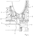
- FIG. 1 shows an example of a wheel processing machine 5.
- a wheel processing machine means that a wheel set 1 is brought to a specific position via appropriate transport routes, as shown in the figures.
- the wheel set 1 is set in rotation by drive rollers 6.
- a tool holder / clamping unit 3 is in the example of Figure 1 equipped with a turning tool 2.1 and can be positioned on the support 4 in a defined manner.
- the set of wheels set in rotation can now be machined using a turning tool 2.1.
- Reference number 6 denotes the axial guide roller, which absorbs axially occurring forces and axially fixes the wheel set 1.
- a rolling tool 2.2 is used so that, for example, following reprofiling by turning, deep rolling can now take place.
- the machine 1 can also be provided with a measuring tool 8 with measuring probes.
- a subsequent measurement can be carried out directly, for example after reprofiling and / or also after deep rolling.
- the measuring tool 8 is integrated in the support and can be moved out next to the holder 3.
Landscapes
- Engineering & Computer Science (AREA)
- Mechanical Engineering (AREA)
- Chemical & Material Sciences (AREA)
- Crystallography & Structural Chemistry (AREA)
- Materials Engineering (AREA)
- Metallurgy (AREA)
- Organic Chemistry (AREA)
- Turning (AREA)
Description
Die vorliegende Erfindung betrifft ein Verfahren zur Bearbeitung der Radlaufflächen von Rädern für: Schienenfahrzeuge gemäß dem Oberbegriff des Anspruchs 1. Ein solches Verfahren ist aus der
Radsätze von Schienenfahrzeugen sind dafür ausgelegt, durch ständigen Kontakt zwischen Rad und Schiene eine sichere Abstützung und Führung des Schienenfahrzeuges zu gewährleisten. Die Radsätze werden durch diesen Rollkontakt unmittelbar beansprucht und sind für eine kontrollierte Fahrzeugbewegung sicherheitsrelevant. Im Zusammenwirken mit der Schiene bestimmt die Geometrie der Radlauffläche den Lauf der Fahrzeuge. In der Instandhaltung von Schienenfahrzeugen kommt dem Radsatz daher eine besondere Bedeutung zu. Die hohen Anforderungen an die Zuverlässigkeit und Qualität erfordern eine regelmäßige Kontrolle und Beurteilung des aktuellen Bauteilzustandes und des verfügbaren Verschleißvorrates.Wheelsets of rail vehicles are designed to ensure safe support and guidance of the rail vehicle through constant contact between wheel and rail. The wheel sets are directly stressed by this rolling contact and are safety-relevant for a controlled vehicle movement. In interaction with the rail, the geometry of the wheel tread determines the way the vehicles run. The wheelset is therefore of particular importance in the maintenance of rail vehicles. The high demands on reliability and quality require regular control and assessment of the current component condition and the available wear reserve.
Das Rad-Schiene-System unterliegt im Fahrbetrieb durch die permanenten Gleit- und Rollbewegungen verschiedenen Verschleißmechanismen. Die daraus folgende Deformation des Radlaufflächenprofils stellt neben einer akustischen Störquelle für die Fahrgäste und Umgebung auch eine Gefahr des Materialversagens für den Radsatz und die umliegenden Bauteile, wie beispielswiese Radlager und Fahrwerk dar. Dieses Problem soll durch das sogenannte Reprofilieren des Radlaufflächenprofils weitgehend vermieden werden.The wheel-rail system is subject to various wear mechanisms during operation due to the permanent sliding and rolling movements. The resulting deformation of the wheel tread profile represents a source of acoustic interference for the passengers and the environment as well as a risk of material failure for the wheelset and the surrounding components, such as wheel bearings and chassis. This problem is to be largely avoided by re-profiling the wheel tread profile.
Bei der Gestaltung des Profils der Radlaufflächen wird eine sichere, fahrkomfortable und verschleißarme Führung angestrebt. Deshalb werden Konturen realisiert, die den natürlichen Verschleiß zwischen Rad und Schiene berücksichtigen. Im Idealfall sollen sich die Konturen während des Betriebes der Schienenfahrzeuge nicht oder nur geringfügig verändern.When designing the profile of the wheel treads, a safe, comfortable and low-wear guide is sought. This is why contours are created that take the natural wear and tear between wheel and rail into account. In the ideal case, the contours should not change or should change only slightly during the operation of the rail vehicles.
Der entstehende Verschleiß durch den Werkstoffabtrag an Rad und Schiene ist primär von der Reibleistung in der Kontaktzone und von der Werkstoffpaarung abhängig. Grundsätzlich wird dabei zwischen einem Laufflächen- und Spurkranzverschleiß unterschieden. Durch Zusammenlegung dieser beiden Verschleißprofile ergibt sich ein mögliches Verschleißprofil, welches zu reprofilieren ist.The resulting wear due to material removal from the wheel and rail is primarily dependent on the friction in the contact zone and on the material pairing. A basic distinction is made between tread wear and wheel flange wear. Merging these two wear profiles results in a possible wear profile that needs to be reprofiled.
Eine derartige Reprofilierung kann mit Radsatzbearbeitungsmaschinen durchgeführt werden, die in verschiedenartigen Varianten bekannt sind, zum Beispiel als Unterflur- oder Überflur-Ausführung sowie in Flachbett- und Portalbauweise. Mit den Radsatzbearbeitungsmaschinen werden die Radlaufflächen unter Anwendung von spanabhebenden Verfahren, vorzugsweise mittels Drehen bearbeitet, so dass diese Maschinen auch als Radsatzdrehmaschinen bezeichnet werden.Such re-profiling can be carried out with wheelset processing machines, which are known in various types, for example as an underfloor or above-floor design as well as in flatbed and portal designs. With the wheelset processing machines, the wheel running surfaces are processed using machining processes, preferably by turning, so that these machines are also referred to as wheelset lathes.
Ausgehend von der Erkenntnis, dass durch Einbringen von Druckeigenspannungen in die Oberflächen rotationssymmetrischer Körper das Verschleißverhalten verbessert werden kann, wurde bereits vorgeschlagen, ausgewählte Abschnitte von Radsätzen unmittelbar nach der Radherstellung im Neuzustand oder später nach einer erfolgreichen Reprofilierung einer zusätzlichen Festwalzbearbeitung zu unterziehen. Somit kann eine Erhöhung der weiteren Lebensdauer der Radlaufflächen durch das Festwalzen erreicht werden.Based on the knowledge that the wear behavior can be improved by introducing residual compressive stresses into the surfaces of rotationally symmetrical bodies, it has already been proposed that selected sections of wheelsets be subjected to additional deep rolling immediately after the wheel has been manufactured or later after successful reprofiling. An increase in the further service life of the wheel running surfaces can thus be achieved by deep rolling.
Das Festwalzen der Oberfläche ist ein mechanisches minimalinvasives Umformen der Bauteilrandschicht. Dabei werden geeignete Walzkörper unter Anpressdruck definiert über die Oberfläche des fertigen Bauteils geführt. Der direkte Bauteil-Kontaktbereich wird plastisch und der angrenzende Kontaktbereich wird elastisch verformt. In Abhängigkeit der jeweils konkreten Kontaktverhältnisse wird lediglich die Oberfläche geglättet, wobei kleine Kerben eingeebnet werden oder der Werkstoff im plastisch verformten Volumen verfestigt wird.The deep rolling of the surface is a mechanical, minimally invasive reshaping of the component edge layer. Suitable rolling elements are guided over the surface of the finished component in a defined manner under contact pressure. The direct component contact area becomes plastic and the adjacent contact area is elastically deformed. Depending on the specific contact conditions, only the surface is smoothed, with small notches being leveled or the material solidified in the plastically deformed volume.
Bei Anwendung des Festwalzens für Radsätze wird somit durch die Kaltverfestigung der Radlaufflächen eine Glättung beziehungsweise Reduzierung der Oberflächenrauheit, eine Aufhärtung der Randschicht und eine Einbringung von Druckeigenspannungen in die Randzone erreicht. Durch die Umformung können in der Werkstückrandschicht vorhandene schädliche Eigenspannungen aus der spanenden Vorbearbeitung abgebaut werden. Im Zusammenwirken von elastischen und plastischen Verformungen wird ein festigkeitsmäßig vorteilhafter Eigenspannungszustand neu aufgeprägt. In der äußeren Randschicht sind nach dem Festwalzen Druckeigenspannungen vorhanden, die eine Verminderung des Verschleißes der Radlaufflächen beziehungsweise eine Steigerung der Laufleistung der Schienenfahrzeugräder bewirken. Dadurch werden sowohl das Auftreten eventueller Risse als auch deren Fortschreiten erheblich eingeschränkt. Diese ausschließlich mechanische Oberflächenbehandlung durch Festwalzen ist ein sehr effektives, umweltfreundliches und ressourcenschonendes Verfahren.When deep rolling is used for wheel sets, the strain hardening of the wheel running surfaces smooths or reduces the surface roughness, hardens the surface layer and introduces residual compressive stresses into the edge zone. The reshaping can reduce the harmful internal stresses present in the workpiece surface layer from the machining pre-machining. In the interaction of elastic and plastic deformations, an internal stress state that is advantageous in terms of strength is newly impressed. After deep rolling, internal compressive stresses are present in the outer surface layer, which reduce the wear on the wheel running surfaces or increase the mileage of the rail vehicle wheels. This significantly limits both the occurrence of possible cracks and their progression. This exclusively mechanical surface treatment by deep rolling is a very effective, environmentally friendly and resource-saving process.
In
Ein weiterer Lösungsansatz zum Festwalzen zylindrischer Wellen ist aus
Mit der Vorrichtung zum Festwalzen von Verschleißflächen am Profil vorgedrehter Radsätze gemäß
Die Vorteile des Festwalzens insbesondere im Anschluss an eine Reprofilierung durch die spanabhebende Bearbeitung, insbesondere Drehen, sind bekannt und umfassend beschrieben.The advantages of deep rolling, especially following reprofiling by machining, in particular turning, are known and have been comprehensively described.
Es hat sich gezeigt, dass das Festwalzen nicht zwingend eine einheitliche Randschicht erzeugt, sodass entweder eine reprofilierte Geometrie mit der die Fläche unterschiedlich verteilten Festigkeitseigenschaften entsteht oder durch das Festwalzen die reprofilierte Geometrie geringfügig verändert wird.It has been shown that deep rolling does not necessarily produce a uniform surface layer, so that either a reprofiled geometry is created with the strength properties distributed differently over the surface or the reprofiled geometry is slightly changed by deep rolling.
So werden nach dem Stand der Technik nach den vorbekannten Verfahren mit den vorgeschlagenen Vorrichtungen gute Ergebnisse in der Walzverfestigung erzielt, jedoch nicht die beschriebenen Unzulänglichkeiten berücksichtigt und ausgeräumt.Thus, according to the prior art, using the previously known methods with the proposed devices, good results in roll hardening are achieved, but the described inadequacies are not taken into account and eliminated.
Ausgehend vom vorbeschriebenen Stand der Technik liegt der vorliegenden Erfindung die Aufgabe zu Grunde, das Verfahren zur Bearbeitung von Radlaufflächen von Schienenfahrzeugen dahingehend zu optimieren, dass auch nach dem Festwalzen eine verbesserte Oberflächenhomogenität bei optimiertem Profil erzielt werden kann.Proceeding from the prior art described above, the present invention is based on the object of optimizing the method for machining wheel running surfaces of rail vehicles such that improved surface homogeneity with an optimized profile can be achieved even after deep rolling.
Verfahrensseitig wird zur technischen Lösung dieser Aufgabe ein Verfahren mit den Merkmalen des Patentanspruches 1 vorgeschlagen. Weitere Vorteile und Merkmale ergeben sich aus den Unteransprüchen.On the process side, a process with the features of
Gemäß dem erfindungsgemäßen Verfahren ist vorgesehen, dass beispielsweise nach einer Reprofilierung in üblicher Weise eine Walzbearbeitung durchgeführt wird. Dabei wird die Walzbearbeitung unter einer definierten und steuerbaren Kraft durchgeführt, so dass das Endergebnis deutlich verbessert ist.According to the method according to the invention, it is provided that, for example, after reprofiling, rolling is carried out in the usual way. The rolling process is carried out under a defined and controllable force so that the end result is significantly improved.
Das erfindungsgemäße Vorgehen hat zum Einen den Vorteil, dass im Endstadium eine weitgehend homogenisierte Oberflächenbeschaffenheit bei optimierter geometrischer Ausbildung des Rades erreicht ist. Sowohl in Abhängigkeit von dem jeweiligen Walzort und der Lage der jeweiligen Festwalzrolle, ggf. auch ihrer Geometrie lässt sich nunmehr an jeder zu bearbeitenden Stelle eine definierte Walzkraft anwenden und somit ein optimales Endergebnis erzielt werden.The procedure according to the invention has the advantage, on the one hand, that in the final stage a largely homogenized surface quality is achieved with an optimized geometric design of the wheel. As a function of the respective rolling location and the position of the respective deep rolling roller, possibly also its geometry, a defined rolling force can now be applied at each point to be processed and thus an optimal end result can be achieved.
So kann eine Reprofilierung durch mehrfach aufeinander folgende Schritte des Vermessens und des spanabhebenden Bearbeitens durchgeführt werden. Die spanabhebende Bearbeitung ist vorzugsweise Drehen. Aber selbstverständlich sind auch andere Verfahren einsetzbar, die möglicherweise zeitoptimiert verwendet werden können. Darunter zählen Schleifen, Fräsen und dergleichen. Durch die erfindungsgemäße Ausgestaltung des Verfahrens und die auf das Walzen nachfolgende Nachbearbeitung ergibt sich hier eine größere Flexibilität. Dies führt zu besseren Arbeitsergebnissen in kürzeren Bearbeitungszeiten.Thus, a reprofiling can be carried out through multiple successive steps of measuring and machining. The machining is preferably turning. But of course, other methods can also be used, which can possibly be used in a time-optimized manner. This includes grinding, milling and the like. Due to the design of the method according to the invention and the subsequent finishing after rolling there is greater flexibility here. This leads to better work results in shorter processing times.
In vorteilhafter Weise wird eine Einspannstelle verwendet, um zum Einen das Werkzeug für die spanabhebende Bearbeitung, zum Anderen für das Walzen einsetzen zu können. Diese Einspannposition kann eine definierte Position relativ zum ausgerichteten und zu bearbeitenden Rad haben und somit kann eine optimierte Steuerung eingesetzt werden, die das Rad in kürzester Zeit auf eine optimale Geometrie bringt. Je nach Vorrichtung können eine Vielzahl von Einspannstellen verwendet werden, die flexibel bestückbar sind. Je nach Bearbeitungsvorgang kann dann eine entsprechende Steuerung zum Einsatz kommen.A clamping point is advantageously used in order to be able to use the tool for machining on the one hand and for rolling on the other. This clamping position can have a defined position relative to the aligned wheel to be machined and thus an optimized control can be used, which brings the wheel to an optimal geometry in the shortest possible time. Depending on the device, a large number of clamping points can be used, which can be flexibly equipped. A corresponding control can then be used depending on the machining process.
Mit der Erfindung wird ein neuartiges Verfahren zur Bearbeitung der Radlaufflächen von Radsätzen für Schienenfahrzeuge bereitgestellt, welches an beliebigen Maschinen, Unterflur, Überflur, mobil und dergleichen einsetzbar ist. Es optimiert zum Einen die Bearbeitungszeit, zum Anderen die endgültige Radgeometrie. Darüber hinaus wird die Oberflächenqualität des gewalzten Rades deutlich verbessert, woraus eine verlängerte Standzeit resultieren kann.The invention provides a novel method for machining the wheel running surfaces of wheel sets for rail vehicles, which can be used on any machines, underfloor, abovefloor, mobile and the like. On the one hand, it optimizes the machining time and, on the other hand, the final wheel geometry. In addition, the surface quality of the rolled wheel is significantly improved, which can result in a longer service life.
Es ist möglich, aufeinanderfolgende spanabhebende Bearbeitungen einerseits und festwalzende Bearbeitungen andererseits in beliebiger Reihenfolge durchzuführen und diese durch entsprechende Vermessungen zu ergänzen. Auf diese Weise kann in zeit- und geometrieoptimierter Weise eine sehr präzise Bearbeitung und Steuerung erfolgen. Darüber hinaus können sehr flexibel Werkzeuge für die Spanbearbeitung einerseits und unterschiedliche Walzeinheiten eingesetzt werden, je nachdem, ob Teilprofile oder Gesamtprofile bearbeitet werden.It is possible to carry out successive machining operations on the one hand and deep-rolling operations on the other hand in any order and to supplement these with corresponding measurements. In this way, a very precise processing and control can take place in a time and geometry-optimized manner. In addition, tools for chip processing on the one hand and different rolling units can be used very flexibly, depending on whether partial or total profiles are being processed.
Gemäß der Erfindung wird eine mit geringem wirtschaftlichem Aufwand umsetzbare Lösung bereitgestellt, mit welcher optimierte Rädergeometrien herstellbar sind. Insbesondere kann die Erfindung auch erhebliche Zeiteinsparungen mit sich bringen. Weitere Vorteile und Merkmale ergeben sich aus der Beschreibung anhand der Figuren. Dabei zeigen:
- Fig. 1
- eine perspektivische Darstellung einer Vorrichtung zur Durchführung des erfindungsgemäßen Verfahrens in einer Reprofilierungskonstellation;
- Fig. 2
- eine Darstellung gemäß
Fig. 1 in einer Walzkonstellation und - Fig. 3
- eine Darstellung gemäß
Fig. 1 in einer Messkonstellation.
- Fig. 1
- a perspective view of a device for performing the method according to the invention in a reprofiling constellation;
- Fig. 2
- a representation according to
Fig. 1 in a rolling constellation and - Fig. 3
- a representation according to
Fig. 1 in a measurement constellation.
In den Figuren sind gleiche Elemente mit gleichen Bezugszeichen versehen. Die Figuren zeigen beispielhaft eine Radbearbeitungsmaschine 5. Eine Radbearbeitungsmaschine bedeutet, dass ein Radsatz 1 über entsprechende Transportwege an eine bestimmte Position gebracht wird, wie sie in den Figuren gezeigt ist. Der Radsatz 1 wird durch Antriebsrollen 6 in Drehung versetzt. Ein Werkzeughalter/Einspanneinheit 3 ist im Beispiel der
In den Werkzeughalter 3 ist gemäß
In der besonderen Ausführungsform kann die Maschine 1 auch mit einem Vermessungswerkzeug 8 mit Messtastern versehen werden. Auf diese Weise kann direkt eine anschließende Vermessung beispielsweise nach der Reprofilierung und/oder auch nach dem Festwalzen durchgeführt werden. Das Vermessungswerkzeug 8 ist im Support integriert und kann neben dem Halter 3 herausgefahren werden.In the particular embodiment, the
Das beschriebene Ausführungsbeispiel dient nur der Erläuterung und ist nicht beschränkend.The exemplary embodiment described serves only for explanation and is not restrictive.
- 1.1.
- RadsatzWheelset
- 2.12.1
- DrehwerkzeugTurning tool
- 2.22.2
- WalzwerkzeugRolling tool
- 3.3.
- EinspanneinheitClamping unit
- 4.4th
- WerkzeugsupportTool support
- 5.5.
- RadbearbeitungsmaschineWheel processing machine
- 6.6th
- AntriebsrolleDrive roller
- 7.7th
- Axiale FührungsrolleAxial guide role
- 8.8th.
- MesseinrichtungMeasuring device
Claims (7)
- Method for machining the wheel running surfaces of wheels for rail vehicles by means of a wheel machining machine, wherein in a process step a rolling process is performed on the wheels with a work roller, characterised in that the rolling force can be adjusted by controlling the torques of drive motors of the feed axles of the rolling tool (2.2).
- Method in accordance with Claim 1, characterised in that the rolling process, after a basic setting of the wheels and the processing machine relative to one another, follows a reprofiling by at least one measurement of the wheels and a machining of the wheels.
- Method in accordance with Claim 2, characterised in that, for reprofiling, measurement and machining are carried out multiple times successively until a specified reprofiling result is achieved.
- Method in accordance with one of the preceding Claims, characterised in that machining is effected by turning.
- Method in accordance with one of the preceding Claims, characterised in that for machining on the one hand and for the rolling process on the other hand, respectively, a tool (2.1 or 2.2) clamped in the same clamping position is used.
- Method in accordance with one of the preceding Claims, characterised in that a measurement is carried out after the rolling process.
- Method in accordance with one of the preceding Claims, characterised in that this is applicable to individual partial profiles of a wheel.
Priority Applications (2)
| Application Number | Priority Date | Filing Date | Title |
|---|---|---|---|
| ES19182039T ES2840749T3 (en) | 2017-03-13 | 2017-03-13 | Procedure for machining the rolling surfaces of rail wheels for railway vehicles |
| EP19182039.8A EP3581325B1 (en) | 2017-03-13 | 2017-03-13 | Method for the treatment of wheel treads of wheels for railway vehicles |
Applications Claiming Priority (2)
| Application Number | Priority Date | Filing Date | Title |
|---|---|---|---|
| EP17160611.4A EP3375561B8 (en) | 2017-03-13 | 2017-03-13 | Method and device for machining of wheel treads of wheels for railway vehicles |
| EP19182039.8A EP3581325B1 (en) | 2017-03-13 | 2017-03-13 | Method for the treatment of wheel treads of wheels for railway vehicles |
Related Parent Applications (2)
| Application Number | Title | Priority Date | Filing Date |
|---|---|---|---|
| EP17160611.4A Division-Into EP3375561B8 (en) | 2017-03-13 | 2017-03-13 | Method and device for machining of wheel treads of wheels for railway vehicles |
| EP17160611.4A Division EP3375561B8 (en) | 2017-03-13 | 2017-03-13 | Method and device for machining of wheel treads of wheels for railway vehicles |
Publications (2)
| Publication Number | Publication Date |
|---|---|
| EP3581325A1 EP3581325A1 (en) | 2019-12-18 |
| EP3581325B1 true EP3581325B1 (en) | 2020-10-14 |
Family
ID=58314134
Family Applications (2)
| Application Number | Title | Priority Date | Filing Date |
|---|---|---|---|
| EP17160611.4A Active EP3375561B8 (en) | 2017-03-13 | 2017-03-13 | Method and device for machining of wheel treads of wheels for railway vehicles |
| EP19182039.8A Active EP3581325B1 (en) | 2017-03-13 | 2017-03-13 | Method for the treatment of wheel treads of wheels for railway vehicles |
Family Applications Before (1)
| Application Number | Title | Priority Date | Filing Date |
|---|---|---|---|
| EP17160611.4A Active EP3375561B8 (en) | 2017-03-13 | 2017-03-13 | Method and device for machining of wheel treads of wheels for railway vehicles |
Country Status (3)
| Country | Link |
|---|---|
| EP (2) | EP3375561B8 (en) |
| ES (2) | ES2783899T3 (en) |
| PL (1) | PL3375561T3 (en) |
Families Citing this family (3)
| Publication number | Priority date | Publication date | Assignee | Title |
|---|---|---|---|---|
| CN110202384B (en) * | 2019-06-28 | 2024-06-25 | 烟台瑞斯克数控机械有限公司 | Adjustable single-side rolling double-angle forming integrated numerical control machining machine for metal plates |
| AT525536B1 (en) | 2022-04-27 | 2023-05-15 | Siemens Mobility Austria Gmbh | Wave |
| CN115338673B (en) * | 2022-07-27 | 2023-11-21 | 湘潭大学 | Wheel tread processing method and turning machine |
Family Cites Families (9)
| Publication number | Priority date | Publication date | Assignee | Title |
|---|---|---|---|---|
| DE808197C (en) | 1949-07-28 | 1951-07-12 | Wilhelm Hegenscheidt K G | Embossing roller for embossing shaft parts, especially the steering knuckle and emergency runs of wheel sets |
| DE843822C (en) | 1950-04-27 | 1952-07-14 | Wilhelm Hegenscheidt Kommandit | Device for polishing cylindrical workpieces, such as B. of shaft parts |
| DE1803783U (en) * | 1959-10-19 | 1960-01-07 | Wilhelm Hegenscheidt Kommandit | UNDERGROUND MACHINE FOR WHEEL SETS IN NOT DISMOUNTED RAILWAY VEHICLES. |
| DE1857319U (en) * | 1962-05-18 | 1962-08-23 | Wilhelm Hegenscheidt Kommandit | DEVICE FOR ROLLING WHEEL SET PROFILES. |
| DE1278274B (en) | 1965-01-25 | 1968-09-19 | Wilhelm Hegenscheidt Kommandit | Device for smooth and deep rolling of wear surfaces on the profile of pre-turned railway wheel sets |
| US4835826A (en) * | 1986-12-01 | 1989-06-06 | The B.F. Goodrich Company | Method of burnishing |
| US7188398B2 (en) * | 2004-01-17 | 2007-03-13 | Surface Technology Holdings, Ltd. | Method for improving the magnitude of compressive stress developed in the surface of a part |
| UA77086C2 (en) * | 2004-12-13 | 2006-10-16 | Viktor Serhiiovych Lukonin | Method and machine tool for reinforcement of working surface of flange and near-flange surface of rolling of wheels of wheelpairs of the rail transport |
| DE202014007648U1 (en) * | 2014-09-18 | 2015-12-22 | Hegenscheidt Mfd Gmbh | Rolling unit for deep rolling the wheel treads of rail vehicles |
-
2017
- 2017-03-13 ES ES17160611T patent/ES2783899T3/en active Active
- 2017-03-13 ES ES19182039T patent/ES2840749T3/en active Active
- 2017-03-13 EP EP17160611.4A patent/EP3375561B8/en active Active
- 2017-03-13 PL PL17160611T patent/PL3375561T3/en unknown
- 2017-03-13 EP EP19182039.8A patent/EP3581325B1/en active Active
Non-Patent Citations (1)
| Title |
|---|
| None * |
Also Published As
| Publication number | Publication date |
|---|---|
| PL3375561T3 (en) | 2020-07-27 |
| EP3375561B1 (en) | 2020-02-26 |
| EP3375561B8 (en) | 2020-10-21 |
| ES2783899T3 (en) | 2020-09-18 |
| EP3375561A1 (en) | 2018-09-19 |
| ES2840749T3 (en) | 2021-07-07 |
| EP3581325A1 (en) | 2019-12-18 |
Similar Documents
| Publication | Publication Date | Title |
|---|---|---|
| EP1525073B1 (en) | Method and device for grinding a rotationally symmetric machine part | |
| EP1039984B1 (en) | Method and device for polishing workpieces with a simultaneous superfinish | |
| EP2823924B1 (en) | Double dressing unit | |
| EP3310530B1 (en) | Method and grinding machine for grinding external and internal contours of workpieces in one set-up | |
| EP3283257B1 (en) | Method and system for grinding the exterior of shaft parts between tips | |
| DE19919893A1 (en) | Pre- and finish grinding a crankshaft in one setup | |
| EP2167277B1 (en) | Grinding center and method for simultaneous grinding of a plurality of bearings and end-side surfaces of crankshafts | |
| DE4426452C1 (en) | Process for grinding concave flanks of cams of camshaft | |
| EP1427568B1 (en) | Method and device for grinding central bearing positions on crankshafts | |
| EP2588273B1 (en) | Machine for deep-rolling axles | |
| DE102008007175B4 (en) | Method for grinding the main and stroke bearings of a crankshaft by external cylindrical grinding and apparatus for carrying out the method | |
| EP3581325B1 (en) | Method for the treatment of wheel treads of wheels for railway vehicles | |
| WO2016041540A2 (en) | Rolling unit for deep-rolling the running surfaces of rail vehicles | |
| DE102015204909B4 (en) | Method and grinding machine for grinding workpieces having grooves | |
| EP0598181B1 (en) | Method for working a pair of wheels and device using this method | |
| EP3083137B1 (en) | Method and grinding machine for measuring and producing a target outer contour of a workpiece by means of grinding | |
| DE102010060471A1 (en) | Machine for finishing workpiece, preferably long workpiece, comprises machine frame, finishing unit for workpieces finishing and two parallel-aligned workpiece holders | |
| WO2016198533A1 (en) | Machine and method for fine machining of a metal component | |
| DE102010053405A1 (en) | Method for external grinding of work pieces, involves clamping of work pieces at its front surface between work piece spindles, where work pieces are arranged completely on side of imaginary plane by spindle axes |
Legal Events
| Date | Code | Title | Description |
|---|---|---|---|
| PUAI | Public reference made under article 153(3) epc to a published international application that has entered the european phase |
Free format text: ORIGINAL CODE: 0009012 |
|
| STAA | Information on the status of an ep patent application or granted ep patent |
Free format text: STATUS: THE APPLICATION HAS BEEN PUBLISHED |
|
| AC | Divisional application: reference to earlier application |
Ref document number: 3375561 Country of ref document: EP Kind code of ref document: P |
|
| AK | Designated contracting states |
Kind code of ref document: A1 Designated state(s): AL AT BE BG CH CY CZ DE DK EE ES FI FR GB GR HR HU IE IS IT LI LT LU LV MC MK MT NL NO PL PT RO RS SE SI SK SM TR |
|
| AX | Request for extension of the european patent |
Extension state: BA ME |
|
| STAA | Information on the status of an ep patent application or granted ep patent |
Free format text: STATUS: REQUEST FOR EXAMINATION WAS MADE |
|
| 17P | Request for examination filed |
Effective date: 20200226 |
|
| RBV | Designated contracting states (corrected) |
Designated state(s): AL AT BE BG CH CY CZ DE DK EE ES FI FR GB GR HR HU IE IS IT LI LT LU LV MC MK MT NL NO PL PT RO RS SE SI SK SM TR |
|
| GRAP | Despatch of communication of intention to grant a patent |
Free format text: ORIGINAL CODE: EPIDOSNIGR1 |
|
| STAA | Information on the status of an ep patent application or granted ep patent |
Free format text: STATUS: GRANT OF PATENT IS INTENDED |
|
| RIC1 | Information provided on ipc code assigned before grant |
Ipc: B23P 9/02 20060101AFI20200525BHEP Ipc: C21D 7/08 20060101ALI20200525BHEP Ipc: B24B 39/04 20060101ALI20200525BHEP Ipc: B23B 5/32 20060101ALI20200525BHEP |
|
| INTG | Intention to grant announced |
Effective date: 20200619 |
|
| GRAS | Grant fee paid |
Free format text: ORIGINAL CODE: EPIDOSNIGR3 |
|
| RAP1 | Party data changed (applicant data changed or rights of an application transferred) |
Owner name: HEGENSCHEIDT-MFD GMBH |
|
| GRAA | (expected) grant |
Free format text: ORIGINAL CODE: 0009210 |
|
| STAA | Information on the status of an ep patent application or granted ep patent |
Free format text: STATUS: THE PATENT HAS BEEN GRANTED |
|
| AC | Divisional application: reference to earlier application |
Ref document number: 3375561 Country of ref document: EP Kind code of ref document: P |
|
| AK | Designated contracting states |
Kind code of ref document: B1 Designated state(s): AL AT BE BG CH CY CZ DE DK EE ES FI FR GB GR HR HU IE IS IT LI LT LU LV MC MK MT NL NO PL PT RO RS SE SI SK SM TR |
|
| REG | Reference to a national code |
Ref country code: GB Ref legal event code: FG4D Free format text: NOT ENGLISH |
|
| REG | Reference to a national code |
Ref country code: AT Ref legal event code: REF Ref document number: 1323104 Country of ref document: AT Kind code of ref document: T Effective date: 20201015 Ref country code: CH Ref legal event code: EP |
|
| REG | Reference to a national code |
Ref country code: DE Ref legal event code: R096 Ref document number: 502017007798 Country of ref document: DE |
|
| REG | Reference to a national code |
Ref country code: IE Ref legal event code: FG4D Free format text: LANGUAGE OF EP DOCUMENT: GERMAN |
|
| REG | Reference to a national code |
Ref country code: RO Ref legal event code: EPE |
|
| REG | Reference to a national code |
Ref country code: CH Ref legal event code: NV Representative=s name: DIPL.-ING. AXEL WANISCHECK-BERGMANN, CH |
|
| REG | Reference to a national code |
Ref country code: NL Ref legal event code: MP Effective date: 20201014 |
|
| PG25 | Lapsed in a contracting state [announced via postgrant information from national office to epo] |
Ref country code: PT Free format text: LAPSE BECAUSE OF FAILURE TO SUBMIT A TRANSLATION OF THE DESCRIPTION OR TO PAY THE FEE WITHIN THE PRESCRIBED TIME-LIMIT Effective date: 20210215 Ref country code: RS Free format text: LAPSE BECAUSE OF FAILURE TO SUBMIT A TRANSLATION OF THE DESCRIPTION OR TO PAY THE FEE WITHIN THE PRESCRIBED TIME-LIMIT Effective date: 20201014 Ref country code: FI Free format text: LAPSE BECAUSE OF FAILURE TO SUBMIT A TRANSLATION OF THE DESCRIPTION OR TO PAY THE FEE WITHIN THE PRESCRIBED TIME-LIMIT Effective date: 20201014 Ref country code: NO Free format text: LAPSE BECAUSE OF FAILURE TO SUBMIT A TRANSLATION OF THE DESCRIPTION OR TO PAY THE FEE WITHIN THE PRESCRIBED TIME-LIMIT Effective date: 20210114 Ref country code: GR Free format text: LAPSE BECAUSE OF FAILURE TO SUBMIT A TRANSLATION OF THE DESCRIPTION OR TO PAY THE FEE WITHIN THE PRESCRIBED TIME-LIMIT Effective date: 20210115 |
|
| REG | Reference to a national code |
Ref country code: LT Ref legal event code: MG4D |
|
| PG25 | Lapsed in a contracting state [announced via postgrant information from national office to epo] |
Ref country code: LV Free format text: LAPSE BECAUSE OF FAILURE TO SUBMIT A TRANSLATION OF THE DESCRIPTION OR TO PAY THE FEE WITHIN THE PRESCRIBED TIME-LIMIT Effective date: 20201014 Ref country code: IS Free format text: LAPSE BECAUSE OF FAILURE TO SUBMIT A TRANSLATION OF THE DESCRIPTION OR TO PAY THE FEE WITHIN THE PRESCRIBED TIME-LIMIT Effective date: 20210214 Ref country code: SE Free format text: LAPSE BECAUSE OF FAILURE TO SUBMIT A TRANSLATION OF THE DESCRIPTION OR TO PAY THE FEE WITHIN THE PRESCRIBED TIME-LIMIT Effective date: 20201014 Ref country code: BG Free format text: LAPSE BECAUSE OF FAILURE TO SUBMIT A TRANSLATION OF THE DESCRIPTION OR TO PAY THE FEE WITHIN THE PRESCRIBED TIME-LIMIT Effective date: 20210114 |
|
| PG25 | Lapsed in a contracting state [announced via postgrant information from national office to epo] |
Ref country code: HR Free format text: LAPSE BECAUSE OF FAILURE TO SUBMIT A TRANSLATION OF THE DESCRIPTION OR TO PAY THE FEE WITHIN THE PRESCRIBED TIME-LIMIT Effective date: 20201014 Ref country code: NL Free format text: LAPSE BECAUSE OF FAILURE TO SUBMIT A TRANSLATION OF THE DESCRIPTION OR TO PAY THE FEE WITHIN THE PRESCRIBED TIME-LIMIT Effective date: 20201014 |
|
| REG | Reference to a national code |
Ref country code: ES Ref legal event code: FG2A Ref document number: 2840749 Country of ref document: ES Kind code of ref document: T3 Effective date: 20210707 |
|
| REG | Reference to a national code |
Ref country code: DE Ref legal event code: R097 Ref document number: 502017007798 Country of ref document: DE |
|
| PG25 | Lapsed in a contracting state [announced via postgrant information from national office to epo] |
Ref country code: SM Free format text: LAPSE BECAUSE OF FAILURE TO SUBMIT A TRANSLATION OF THE DESCRIPTION OR TO PAY THE FEE WITHIN THE PRESCRIBED TIME-LIMIT Effective date: 20201014 Ref country code: SK Free format text: LAPSE BECAUSE OF FAILURE TO SUBMIT A TRANSLATION OF THE DESCRIPTION OR TO PAY THE FEE WITHIN THE PRESCRIBED TIME-LIMIT Effective date: 20201014 Ref country code: EE Free format text: LAPSE BECAUSE OF FAILURE TO SUBMIT A TRANSLATION OF THE DESCRIPTION OR TO PAY THE FEE WITHIN THE PRESCRIBED TIME-LIMIT Effective date: 20201014 Ref country code: LT Free format text: LAPSE BECAUSE OF FAILURE TO SUBMIT A TRANSLATION OF THE DESCRIPTION OR TO PAY THE FEE WITHIN THE PRESCRIBED TIME-LIMIT Effective date: 20201014 |
|
| PLBE | No opposition filed within time limit |
Free format text: ORIGINAL CODE: 0009261 |
|
| STAA | Information on the status of an ep patent application or granted ep patent |
Free format text: STATUS: NO OPPOSITION FILED WITHIN TIME LIMIT |
|
| PG25 | Lapsed in a contracting state [announced via postgrant information from national office to epo] |
Ref country code: DK Free format text: LAPSE BECAUSE OF FAILURE TO SUBMIT A TRANSLATION OF THE DESCRIPTION OR TO PAY THE FEE WITHIN THE PRESCRIBED TIME-LIMIT Effective date: 20201014 |
|
| 26N | No opposition filed |
Effective date: 20210715 |
|
| PG25 | Lapsed in a contracting state [announced via postgrant information from national office to epo] |
Ref country code: AL Free format text: LAPSE BECAUSE OF FAILURE TO SUBMIT A TRANSLATION OF THE DESCRIPTION OR TO PAY THE FEE WITHIN THE PRESCRIBED TIME-LIMIT Effective date: 20201014 Ref country code: MC Free format text: LAPSE BECAUSE OF FAILURE TO SUBMIT A TRANSLATION OF THE DESCRIPTION OR TO PAY THE FEE WITHIN THE PRESCRIBED TIME-LIMIT Effective date: 20201014 |
|
| PG25 | Lapsed in a contracting state [announced via postgrant information from national office to epo] |
Ref country code: SI Free format text: LAPSE BECAUSE OF FAILURE TO SUBMIT A TRANSLATION OF THE DESCRIPTION OR TO PAY THE FEE WITHIN THE PRESCRIBED TIME-LIMIT Effective date: 20201014 |
|
| REG | Reference to a national code |
Ref country code: BE Ref legal event code: MM Effective date: 20210331 |
|
| PG25 | Lapsed in a contracting state [announced via postgrant information from national office to epo] |
Ref country code: LU Free format text: LAPSE BECAUSE OF NON-PAYMENT OF DUE FEES Effective date: 20210313 Ref country code: IE Free format text: LAPSE BECAUSE OF NON-PAYMENT OF DUE FEES Effective date: 20210313 |
|
| PG25 | Lapsed in a contracting state [announced via postgrant information from national office to epo] |
Ref country code: IS Free format text: LAPSE BECAUSE OF FAILURE TO SUBMIT A TRANSLATION OF THE DESCRIPTION OR TO PAY THE FEE WITHIN THE PRESCRIBED TIME-LIMIT Effective date: 20210214 |
|
| PG25 | Lapsed in a contracting state [announced via postgrant information from national office to epo] |
Ref country code: BE Free format text: LAPSE BECAUSE OF NON-PAYMENT OF DUE FEES Effective date: 20210331 |
|
| REG | Reference to a national code |
Ref country code: AT Ref legal event code: MM01 Ref document number: 1323104 Country of ref document: AT Kind code of ref document: T Effective date: 20220313 |
|
| PG25 | Lapsed in a contracting state [announced via postgrant information from national office to epo] |
Ref country code: CY Free format text: LAPSE BECAUSE OF FAILURE TO SUBMIT A TRANSLATION OF THE DESCRIPTION OR TO PAY THE FEE WITHIN THE PRESCRIBED TIME-LIMIT Effective date: 20201014 |
|
| PG25 | Lapsed in a contracting state [announced via postgrant information from national office to epo] |
Ref country code: HU Free format text: LAPSE BECAUSE OF FAILURE TO SUBMIT A TRANSLATION OF THE DESCRIPTION OR TO PAY THE FEE WITHIN THE PRESCRIBED TIME-LIMIT; INVALID AB INITIO Effective date: 20170313 Ref country code: AT Free format text: LAPSE BECAUSE OF NON-PAYMENT OF DUE FEES Effective date: 20220313 |
|
| PG25 | Lapsed in a contracting state [announced via postgrant information from national office to epo] |
Ref country code: MK Free format text: LAPSE BECAUSE OF FAILURE TO SUBMIT A TRANSLATION OF THE DESCRIPTION OR TO PAY THE FEE WITHIN THE PRESCRIBED TIME-LIMIT Effective date: 20201014 |
|
| PGFP | Annual fee paid to national office [announced via postgrant information from national office to epo] |
Ref country code: RO Payment date: 20240229 Year of fee payment: 8 Ref country code: DE Payment date: 20240320 Year of fee payment: 8 Ref country code: CZ Payment date: 20240304 Year of fee payment: 8 Ref country code: GB Payment date: 20240320 Year of fee payment: 8 |
|
| PGFP | Annual fee paid to national office [announced via postgrant information from national office to epo] |
Ref country code: PL Payment date: 20240229 Year of fee payment: 8 Ref country code: IT Payment date: 20240329 Year of fee payment: 8 Ref country code: FR Payment date: 20240328 Year of fee payment: 8 |
|
| PG25 | Lapsed in a contracting state [announced via postgrant information from national office to epo] |
Ref country code: TR Free format text: LAPSE BECAUSE OF FAILURE TO SUBMIT A TRANSLATION OF THE DESCRIPTION OR TO PAY THE FEE WITHIN THE PRESCRIBED TIME-LIMIT Effective date: 20201014 |
|
| PGFP | Annual fee paid to national office [announced via postgrant information from national office to epo] |
Ref country code: CH Payment date: 20240401 Year of fee payment: 8 |
|
| PGFP | Annual fee paid to national office [announced via postgrant information from national office to epo] |
Ref country code: ES Payment date: 20240429 Year of fee payment: 8 |