EP3581122B1 - Vasculature obstruction capture device - Google Patents
Vasculature obstruction capture device Download PDFInfo
- Publication number
- EP3581122B1 EP3581122B1 EP19179707.5A EP19179707A EP3581122B1 EP 3581122 B1 EP3581122 B1 EP 3581122B1 EP 19179707 A EP19179707 A EP 19179707A EP 3581122 B1 EP3581122 B1 EP 3581122B1
- Authority
- EP
- European Patent Office
- Prior art keywords
- invertible
- expandable
- elongated member
- obstruction
- core wire
- Prior art date
- Legal status (The legal status is an assumption and is not a legal conclusion. Google has not performed a legal analysis and makes no representation as to the accuracy of the status listed.)
- Active
Links
- 210000005166 vasculature Anatomy 0.000 title claims description 20
- 238000000034 method Methods 0.000 description 14
- 208000005189 Embolism Diseases 0.000 description 4
- 210000004204 blood vessel Anatomy 0.000 description 4
- 230000006835 compression Effects 0.000 description 4
- 238000007906 compression Methods 0.000 description 4
- RTZKZFJDLAIYFH-UHFFFAOYSA-N Diethyl ether Chemical compound CCOCC RTZKZFJDLAIYFH-UHFFFAOYSA-N 0.000 description 2
- 208000032382 Ischaemic stroke Diseases 0.000 description 2
- 210000002376 aorta thoracic Anatomy 0.000 description 2
- 230000015572 biosynthetic process Effects 0.000 description 2
- 230000017531 blood circulation Effects 0.000 description 2
- 210000001627 cerebral artery Anatomy 0.000 description 2
- 206010007027 Calculus urinary Diseases 0.000 description 1
- 102000009123 Fibrin Human genes 0.000 description 1
- 108010073385 Fibrin Proteins 0.000 description 1
- BWGVNKXGVNDBDI-UHFFFAOYSA-N Fibrin monomer Chemical compound CNC(=O)CNC(=O)CN BWGVNKXGVNDBDI-UHFFFAOYSA-N 0.000 description 1
- 208000009911 Urinary Calculi Diseases 0.000 description 1
- 238000013459 approach Methods 0.000 description 1
- 210000001367 artery Anatomy 0.000 description 1
- 230000036772 blood pressure Effects 0.000 description 1
- 210000004556 brain Anatomy 0.000 description 1
- 230000002490 cerebral effect Effects 0.000 description 1
- 230000001419 dependent effect Effects 0.000 description 1
- 229950003499 fibrin Drugs 0.000 description 1
- 238000010348 incorporation Methods 0.000 description 1
- 238000003780 insertion Methods 0.000 description 1
- 230000037431 insertion Effects 0.000 description 1
- 239000000463 material Substances 0.000 description 1
- 238000012986 modification Methods 0.000 description 1
- 230000004048 modification Effects 0.000 description 1
- 239000002245 particle Substances 0.000 description 1
- 210000000626 ureter Anatomy 0.000 description 1
- 230000002792 vascular Effects 0.000 description 1
Images


Classifications
-
- A—HUMAN NECESSITIES
- A61—MEDICAL OR VETERINARY SCIENCE; HYGIENE
- A61B—DIAGNOSIS; SURGERY; IDENTIFICATION
- A61B17/00—Surgical instruments, devices or methods, e.g. tourniquets
- A61B17/22—Implements for squeezing-off ulcers or the like on the inside of inner organs of the body; Implements for scraping-out cavities of body organs, e.g. bones; Calculus removers; Calculus smashing apparatus; Apparatus for removing obstructions in blood vessels, not otherwise provided for
- A61B17/221—Gripping devices in the form of loops or baskets for gripping calculi or similar types of obstructions
-
- A—HUMAN NECESSITIES
- A61—MEDICAL OR VETERINARY SCIENCE; HYGIENE
- A61B—DIAGNOSIS; SURGERY; IDENTIFICATION
- A61B17/00—Surgical instruments, devices or methods, e.g. tourniquets
- A61B17/22—Implements for squeezing-off ulcers or the like on the inside of inner organs of the body; Implements for scraping-out cavities of body organs, e.g. bones; Calculus removers; Calculus smashing apparatus; Apparatus for removing obstructions in blood vessels, not otherwise provided for
- A61B17/22031—Gripping instruments, e.g. forceps, for removing or smashing calculi
- A61B17/22032—Gripping instruments, e.g. forceps, for removing or smashing calculi having inflatable gripping elements
-
- A—HUMAN NECESSITIES
- A61—MEDICAL OR VETERINARY SCIENCE; HYGIENE
- A61B—DIAGNOSIS; SURGERY; IDENTIFICATION
- A61B17/00—Surgical instruments, devices or methods, e.g. tourniquets
- A61B17/22—Implements for squeezing-off ulcers or the like on the inside of inner organs of the body; Implements for scraping-out cavities of body organs, e.g. bones; Calculus removers; Calculus smashing apparatus; Apparatus for removing obstructions in blood vessels, not otherwise provided for
-
- A—HUMAN NECESSITIES
- A61—MEDICAL OR VETERINARY SCIENCE; HYGIENE
- A61F—FILTERS IMPLANTABLE INTO BLOOD VESSELS; PROSTHESES; DEVICES PROVIDING PATENCY TO, OR PREVENTING COLLAPSING OF, TUBULAR STRUCTURES OF THE BODY, e.g. STENTS; ORTHOPAEDIC, NURSING OR CONTRACEPTIVE DEVICES; FOMENTATION; TREATMENT OR PROTECTION OF EYES OR EARS; BANDAGES, DRESSINGS OR ABSORBENT PADS; FIRST-AID KITS
- A61F2/00—Filters implantable into blood vessels; Prostheses, i.e. artificial substitutes or replacements for parts of the body; Appliances for connecting them with the body; Devices providing patency to, or preventing collapsing of, tubular structures of the body, e.g. stents
- A61F2/01—Filters implantable into blood vessels
- A61F2/013—Distal protection devices, i.e. devices placed distally in combination with another endovascular procedure, e.g. angioplasty or stenting
-
- A—HUMAN NECESSITIES
- A61—MEDICAL OR VETERINARY SCIENCE; HYGIENE
- A61B—DIAGNOSIS; SURGERY; IDENTIFICATION
- A61B17/00—Surgical instruments, devices or methods, e.g. tourniquets
- A61B2017/00743—Type of operation; Specification of treatment sites
- A61B2017/00778—Operations on blood vessels
-
- A—HUMAN NECESSITIES
- A61—MEDICAL OR VETERINARY SCIENCE; HYGIENE
- A61B—DIAGNOSIS; SURGERY; IDENTIFICATION
- A61B17/00—Surgical instruments, devices or methods, e.g. tourniquets
- A61B17/22—Implements for squeezing-off ulcers or the like on the inside of inner organs of the body; Implements for scraping-out cavities of body organs, e.g. bones; Calculus removers; Calculus smashing apparatus; Apparatus for removing obstructions in blood vessels, not otherwise provided for
- A61B17/22031—Gripping instruments, e.g. forceps, for removing or smashing calculi
- A61B2017/22034—Gripping instruments, e.g. forceps, for removing or smashing calculi for gripping the obstruction or the tissue part from inside
-
- A—HUMAN NECESSITIES
- A61—MEDICAL OR VETERINARY SCIENCE; HYGIENE
- A61B—DIAGNOSIS; SURGERY; IDENTIFICATION
- A61B17/00—Surgical instruments, devices or methods, e.g. tourniquets
- A61B17/22—Implements for squeezing-off ulcers or the like on the inside of inner organs of the body; Implements for scraping-out cavities of body organs, e.g. bones; Calculus removers; Calculus smashing apparatus; Apparatus for removing obstructions in blood vessels, not otherwise provided for
- A61B2017/22038—Implements for squeezing-off ulcers or the like on the inside of inner organs of the body; Implements for scraping-out cavities of body organs, e.g. bones; Calculus removers; Calculus smashing apparatus; Apparatus for removing obstructions in blood vessels, not otherwise provided for with a guide wire
-
- A—HUMAN NECESSITIES
- A61—MEDICAL OR VETERINARY SCIENCE; HYGIENE
- A61B—DIAGNOSIS; SURGERY; IDENTIFICATION
- A61B17/00—Surgical instruments, devices or methods, e.g. tourniquets
- A61B17/22—Implements for squeezing-off ulcers or the like on the inside of inner organs of the body; Implements for scraping-out cavities of body organs, e.g. bones; Calculus removers; Calculus smashing apparatus; Apparatus for removing obstructions in blood vessels, not otherwise provided for
- A61B2017/22051—Implements for squeezing-off ulcers or the like on the inside of inner organs of the body; Implements for scraping-out cavities of body organs, e.g. bones; Calculus removers; Calculus smashing apparatus; Apparatus for removing obstructions in blood vessels, not otherwise provided for with an inflatable part, e.g. balloon, for positioning, blocking, or immobilisation
-
- A—HUMAN NECESSITIES
- A61—MEDICAL OR VETERINARY SCIENCE; HYGIENE
- A61B—DIAGNOSIS; SURGERY; IDENTIFICATION
- A61B17/00—Surgical instruments, devices or methods, e.g. tourniquets
- A61B17/22—Implements for squeezing-off ulcers or the like on the inside of inner organs of the body; Implements for scraping-out cavities of body organs, e.g. bones; Calculus removers; Calculus smashing apparatus; Apparatus for removing obstructions in blood vessels, not otherwise provided for
- A61B2017/22094—Implements for squeezing-off ulcers or the like on the inside of inner organs of the body; Implements for scraping-out cavities of body organs, e.g. bones; Calculus removers; Calculus smashing apparatus; Apparatus for removing obstructions in blood vessels, not otherwise provided for for crossing total occlusions, i.e. piercing
-
- A—HUMAN NECESSITIES
- A61—MEDICAL OR VETERINARY SCIENCE; HYGIENE
- A61B—DIAGNOSIS; SURGERY; IDENTIFICATION
- A61B17/00—Surgical instruments, devices or methods, e.g. tourniquets
- A61B17/22—Implements for squeezing-off ulcers or the like on the inside of inner organs of the body; Implements for scraping-out cavities of body organs, e.g. bones; Calculus removers; Calculus smashing apparatus; Apparatus for removing obstructions in blood vessels, not otherwise provided for
- A61B17/221—Gripping devices in the form of loops or baskets for gripping calculi or similar types of obstructions
- A61B2017/2212—Gripping devices in the form of loops or baskets for gripping calculi or similar types of obstructions having a closed distal end, e.g. a loop
-
- A—HUMAN NECESSITIES
- A61—MEDICAL OR VETERINARY SCIENCE; HYGIENE
- A61B—DIAGNOSIS; SURGERY; IDENTIFICATION
- A61B17/00—Surgical instruments, devices or methods, e.g. tourniquets
- A61B17/34—Trocars; Puncturing needles
- A61B17/3417—Details of tips or shafts, e.g. grooves, expandable, bendable; Multiple coaxial sliding cannulas, e.g. for dilating
- A61B17/3421—Cannulas
- A61B2017/3435—Cannulas using everted sleeves
Definitions
- the present invention generally relates to medical devices which can be used to remove an obstruction in a blood vessel within a patient, and more particularly, to devices for capturing obstructions in cerebral arteries.
- Navigating vessels to approach brain arteries can be difficult due to the aortic arch (especially with in patients with type 2 or type 3 aortic arches), vessel segments having sharp, frequent bends, and the fragility of neurovascular vessels compared to similarly sized vessels in other parts of the body.
- the obstruction e.g. clot, misplaced device, migrated device, large emboli, etc.
- Pulsing blood pressure and fibrin formation between the obstruction and the vessel wall can strongly adhere the obstruction to the vessel wall.
- any portion of the obstruction that is not captured and retrieved can be carried in the direction of blood flow.
- An ischemic stroke affecting new territory can result if the free obstruction portion lodges elsewhere in the cerebral vasculature.
- US2016/354098A1 discloses devices and methods relating to structures for removing obstructions from body lumens. Such devices have applicability in through-out the body, including clearing of blockages within the vasculature, by addressing the frictional resistance on the obstruction prior to attempting to translate and/or mobilize the obstruction within the body lumen.
- US9743944B1 discloses a device for removing a urinary tract stone from a ureter including an outer shaft, an inner shaft extending coaxially within the outer shaft, a self-expanding wire basket attached to a basket shaft extending coaxially within the inner shaft, an inflatable balloon and a handle.
- WO2010/102307A1 discloses devices and methods relating to structures for removing obstructions from body lumens.
- US6210370B1 discloses an access device having a single sheath that is inserted into a body passage puncture, with an expandable member of the access device held to a minimum diameter.
- the expandable member is held to the minimum diameter using structure that does not increase the diameter of the access device, rather than a large-diameter external sheath.
- the structure for holding the expandable member to a minimum diameter can subsequently be removed from the lumen of the access device, once the expandable member has been expanded.
- vasculature obstruction capture device capable of capturing an obstruction within a cerebral artery for safe retrieval from the patient.
- the invention is defined in claim 1. Embodiments of the invention are defined in the dependent claims.
- the devices include an expandable element, an invertible element, a gap positioned between the expandable element and the invertible element, and an elongated member for delivering the elements to the site of the obstruction. In this manner, the devices permit for an obstruction to be captured within the gap by enveloping the obstruction within a pocket formed by inverting the inverting element.
- the device for capturing an obstruction in a vasculature includes a first elongated member, an expandable element, an invertible element, and a gap.
- the expandable element and the invertible element are positioned near the distal end of the first elongated member with a gap in between sized to be placed across the obstruction.
- the expandable element expands from a collapsed delivery configuration to an expanded configuration.
- the invertible element expands from a collapsed delivery configuration to an expanded configuration, and the invertible element inverts from the expanded configuration to an inverted configuration, thereby forming a pocket.
- the pocket can envelope at least a portion of the gap and can thereby capture an obstruction that is in the gap.
- the expandable element can be positioned distal to the invertible element.
- the gap can be positioned between a first joint joining the expandable element and the first elongated member and a second joint joining the invertible element and the first elongated member.
- the device includes a core wire with a distal coil positioned near the distal end of the core wire.
- the core wire is movable in relation to the first elongated member, such that the movement expands the expandable element.
- the expanded size of the expandable element, or a radius of expansion, can be controlled by the movement of the core wire in relation to the first elongated member.
- the device can include a second elongated member movable in relation to the first elongated member, such that the movement expands the invertible element.
- Moving the first elongated member in relation to the second elongated member can also invert the invertible element. Inverting the invertible element can cause at least a portion of the gap to be enveloped by the pocket formed by inverting the invertible element.
- the expandable element and the invertible elements can each be expandable to the walls of the vasculature.
- the device can include a clot engaging element positioned between the expandable element and the invertible element.
- the expandable element, invertible element, and clot engaging element can each be disposed near the distal end of the first elongated member.
- the clot engaging element can have a collapsed delivery configuration and can self-expand to an expanded deployed configuration. In the expanded configuration, a portion of the clot engaging element can engage the clot, then upon movement of the clot engaging element, the clot engaging element can pinch the clot in a clot pinching configuration.
- At least a portion of the clot engaging element can be enveloped by the invertible element when the invertible element is in the inverted configuration.
- the expandable element can be positioned distal the invertible element, and the clot engaging element can be positioned distal the invertible element and proximal the expandable element.
- the provided device can have a core wire, a first elongated member, and a second elongated member.
- the method can further include the steps of moving the core wire relative to the first elongated member to cause the expanding of the expandable element, moving the first elongated member relative to the second elongated member to cause the expanding of the invertible element, moving the first elongated member relative to the second elongated member to cause the inverting of the invertible element, moving the first elongated member relative to the second elongated member to cause the enveloping of the at least a portion of the gap, and moving the first elongated member relative to the second elongated member to cause the capturing of the obstruction in the pocket.
- the provided device can have a clot engaging element.
- the method can include the steps of expanding the clot engaging element from a collapsed delivery configuration to an expanded configuration, thereby engaging the obstruction, and moving the clot engaging element from the expanded configuration to a clot pinching configuration, thereby pinching the obstruction.
- An obstruction capturing device 110 as illustrated in Figs. 1a and 1b has a first elongated member 115, an expandable element 112, an invertible element 113, and a gap 125 positioned between the expandable element 112 and the invertible element 113.
- the expandable element 112 can be positioned distal to the invertible element 113 along the first elongated member 115, and the gap 125 can be sized to place across an obstruction.
- Other geometries, not shown are contemplated.
- the expandable element 112 can be positioned proximal to the invertible element 113, with the gap 125 positioned between the expandable 112 and invertible element 113.
- the first elongated member can be an inner tube 115 having a lumen therethrough, a proximal end, and a distal end.
- the inner tube 115 can be connected to the expandable element 112 and the invertible element 113.
- the inner tube 115 can be joined to the proximal end of the expandable element 112 at a joint 119
- the inner tube 115 can be joined to the distal end of the invertible element 113 at a joint 120
- the joints 119, 120 to the inner tube 115 define the gap 125 between the expandable element 112 and the invertible element 113.
- the obstruction capturing device 110 can include additional elongated members such as an outer tube 114 and a core wire 116. As shown in Fig. 1a , the core wire 116, inner tube 115, and outer tube 114 can be concentric with the core wire 116 positioned at the axis of tubes, and the inner tube 115 can be positioned inside of the outer tube 114.
- the core wire 116 can be connected to a distal coil 111 and the expandable element 112.
- the core wire 116 can be joined to the distal coil 111 at two joints 117 on the distal and proximal ends of the distal coil 111, and the core wire 116 can be joined to the expandable element 112 at a joint 118 on the distal end of the expandable element 112.
- the outer tube 114 can be connected to the invertible element 113.
- the outer tube 114 can be connected to the proximal end of the invertible element 113 at a joint 121.
- the expandable element 112 and the invertible element 113 can be in a collapsed delivery configuration.
- the device 110 can be encased in a catheter 103 such as a microcatheter sized to be placed across an obstruction.
- the catheter 103 can be sized to puncture an occlusive clot or other embolus.
- Figs. 2a to 2e illustrate configurations of the obstruction capturing device 110.
- Fig. 2a shows the catheter 103 retracting to expose the expandable element 112.
- Fig. 2b shows the expandable element 112 expanding from the collapsed delivery configuration to an expanded configuration.
- the expansion of the expandable element 112 can be accomplished by pulling the core wire 116 proximally in relation to the inner tube 115.
- the expandable element 112 can be joined to the core wire 116 at a distal joint 118 and joined to the inner tube 115 at a proximal joint 119.
- pulling the core wire 116 proximally in relation to the inner tube 115 can cause the expandable element 112 to be longitudinally compressed. The longitudinal compression can result in the expandable element 112 expanding radially.
- the expandable element 112 can have a flexible structure, such as a mesh, capable of expanding radially when longitudinally compressed or collapsing under longitudinal strain.
- the radius of the expandable element 112 can be controlled by the longitudinal movement of the inner tube 115 in relation to the core wire 116. In certain applications, the radius of expansion can thereby extend to the wall of a vasculature.
- Fig. 2b also shows the catheter 103 retracted to expose the invertible element 113.
- Fig. 2c shows the invertible element 113 expanded from the collapsed delivery configuration into the expanded configuration.
- Fig. 2c also shows the inner tube 115 pulled proximally in relation to the outer tube 114.
- the invertible element 113 can be joined to the inner tube 115 at a distal j oint 120 and joined to the outer tube 114 at a proximal joint 121.
- pulling the inner tube 115 in relation to the outer tube 114 can cause the invertible element 113 to be longitudinally compressed.
- the longitudinal compression can result in the invertible element 113 expanding radially.
- Fig. 2c also shows the expandable element 112 maintaining an expanded configuration. In the example illustration, this can be accomplished by pulling the core wire 116 proximally together with the inner tube 115 as the inner tube 115 is pulled proximally. The simultaneous pull can maintain the spacing between the distal and proximal joints 118, 119 of the expandable element 112 connecting the expandable element 112 to the core wire 116 and the inner tube 115 respectively.
- Fig. 2d shows the invertible element 113 inverting from the expanded configuration to an inverted configuration.
- the inverted configuration can include a concave surface forming a pocket 122.
- the inversion of the invertible element 113 can be accomplished by continuing to pull the inner tube 115 proximally in relation to the outer tube 114. Pulling the inner tube 115 in relation to the outer tube 114 can cause the invertible element 113 to be further longitudinally compressed.
- the longitudinal compression can cause the invertible element 113 to expand, however once the invertible element 113 has reached a maximum expansion, further longitudinal compression can cause the invertible element 113 to invert, or fold in on itself as shown in Fig. 2d .
- at least a portion of the gap 125 can be pulled into the pocket 122, becoming enveloped by the invertible element 113.
- Fig. 2d shows the gap 125 having a length defined by the distance between the joint 119 between the expandable element 112 and the inner tube 115 and the joint 120 between the invertible element 113 and the inner tube 115. Formation of the pocket 122 can cause the joint 120 between the invertible element 113 and the inner tube 115 to advance into the pocket 122 and the expandable element 112 to advance toward the opening of the pocket 122.
- Fig. 2e shows the gap 125 completely enveloped in the pocket 122 of the invertible element 113 and the expandable element 112 butting up against the opening of the pocket 122.
- the pocket 122 and the adjacent surface of the expandable element 112 can form a cavity.
- an invertible element may be positioned distal a proximal element.
- the invertible element can be joined to a core wire at a distal j oint and jointed to an inner tube at a proximal joint.
- the expandable element can be joined to the inner tube at a distal joint and joined to an outer tube at a proximal joint.
- the core wire, inner tube, and outer tube can be elongated members movable by an operator. In such a configuration, moving the outer tube in relation to the inner tube can expand the expandable element, and moving the inner tube in relation to the core wire can expand and invert the invertible element.
- the invertible element can invert to form a pocket that has an opening that faces proximally.
- a cavity can be formed within the pocket of the invertible element capped by an adjacent surface of the expandable element.
- An example method for use of the device in this configuration can include, positioning the gap across an obstruction, pushing the outer tube distally to expand the expandable element, pushing the inner and outer tubes distally to expand and invert the invertible element and envelope the obstruction, moving the microcatheter distally to envelope the device, and extracting the microcatheter from a patient with the device and obstruction contained therein.
- the expandable element 112 can be expanded by means not shown.
- the expandable element 112 can be self-expanding.
- the expandable element 112 can be constrained during delivery by the outer tube 114 or other means and then allowed to expand once the device is positioned to capture the obstruction.
- Figs. 3a to 3f illustrate a method of capturing an obstruction 12 using an obstruction capturing device 110 such as the example devices depicted in Figs. 1a, 1b , and 2a to 2e .
- Fig. 3a shows a device 110 within a vasculature 10, the vasculature 10 containing an obstruction 12 such as an occlusive clot.
- the device 110 can be contained within the catheter 103.
- the distal end of the device 110 is delivered through the obstruction 12 and can be positioned such that the gap 125 is placed across the obstruction 12.
- Fig. 3b shows the catheter 103 retracted to expose the expandable element 112. As shown, the catheter 103 can be retracted to expose the gap 125 such that it is located through the obstruction 12 and a portion of the invertible element 113.
- Fig. 3c shows the expandable element 112 expanding from the collapsed configuration to an expanded configuration, being expanded by moving the core wire 116 in relation to the inner tube 115.
- Fig. 3d shows the expandable element 112 expanded radially outward to the walls of the vasculature 10. In this configuration, the expandable element can thereby prevent distal movement of the obstruction 12.
- Fig. 3d shows the invertible element 113 in the expanded configuration, being expanded by moving the inner tube 115 in relation to the outer tube 114. As shown, the invertible element 113 can be expanded to the walls of the vasculature 10 and can thereby prevent proximal movement of the obstruction 12.
- Fig. 3e shows the invertible element 113 in the inverted configuration and the obstruction 12 being moved into the pocket 122 by moving the inner tube 115 in relation to the outer tube 114.
- the expandable element 112 can move proximally toward the opening of the pocket 122, pushing the obstruction 12 into the pocket 122 and acting to prevent dislodged portions of the clot 12 from passing farther down the vascular 10 in the blood flow.
- Fig. 3f shows the obstruction 12 contained within a cavity formed by the pocket 122 and an adjacent surface of the expandable element 112.
- the obstruction 12 now captured within the cavity, can be removed from the vasculature 10 by pulling the elongated members proximally.
- the obstruction 12 can be removed several ways.
- the device 110 can be reintroduced into the catheter 103 and drawn back encased therein. Alternately, the elongated members can be moved proximately outside the catheter 103. In ether situation, the catheter 103 can be used for aspiration to assure maximum retrieval of all obstruction 12 particles. Further, aspiration may not be necessary, as the combination of the expandable element 112 and the invertible element 113 can assure full obstruction 12 capture.
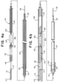
- Figs. 4a and 4b show an example obstruction capturing device 110 that includes a clot engaging element 123.
- the clot engaging element 123 can be any clot or embolus capture/stent retriever known to one of skill in the art. For example, see U.S. Patent Application No. 62/536,005 .
- the example obstruction capturing device 110 includes the elements described in relation to Fig. 1a including the distal coil 111, expandable element 112, invertible element 113, outer tube 114, inner tube 115, core wire 116, and joints 117, 118, 119, 120, 121.
- the clot engaging element 123 can be positioned on the inner tube 115 between the expandable element 112 and the invertible element 113.
- the clot engaging element 123 can be positioned within the gap 125 to facilitate the capturing of a clot or other embolus (e.g. plaque) 12 within the gap 125.
- Figs. 4a and 4b show the expandable element 112, clot engaging element 123, and the invertible element 113 each in a collapsed delivery configuration.
- the device 110 can be encased in a catheter 103 such as a microcatheter sized to be placed across an obstruction 12.
- the catheter 103 can be sized to puncture an occlusive clot or large embolus.
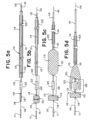
- Figs. 5a to 5e illustrate configurations of the obstruction capturing device 110.
- Fig. 5a shows the catheter 103 retracted to expose the expandable element 112 and the clot engaging element 123.
- the clot engaging element 123 can be self-expanding from the collapsed delivery configuration to an expanded configuration, meaning that when not constrained by the catheter 103 or other means, the clot engaging element 123 can expand to the expanded configuration.
- Fig. 5b shows the expandable element 112 expanding from the collapsed delivery configuration to an expanded configuration by pulling the core wire 116 in relation to the inner tube 115, and Fig. 5b shows the catheter 103 retracted to expose the invertible element 113.
- Fig. 5c shows the invertible element 113 expanded from the collapsed delivery configuration into the expanded configuration by pulling the inner tube 115 proximally in relation to the outer tube 114, and Fig. 5c shows the expandable element 112 maintaining an expanded configuration.
- Fig. 5d shows the invertible element 113 inverting from the expanded configuration to an inverted configuration, forming a pocket 122 around the clot engaging element 123.
- Fig. 5d shows the gap 125 advancing into the pocket 122 and the expandable element 112 advancing toward the opening of the pocket 122.
- Fig. 5e shows the gap 125 completely enveloped in the pocket 122 of the invertible element 113 and the expandable element 112 butting up against the opening of the pocket 122.
- the pocket 122 and the adjacent surface of the expandable element 112 forming a cavity.
- Fig. 6a to 6f illustrate a method of capturing an obstruction 12 using an obstruction capturing device 110 such as the example devices depicted in Figs. 4a, 4b , and 5a to 5e .
- Fig. 6a shows the device 110 contained within the catheter 103 within the vasculature 10, the vasculature 10 containing an obstruction 12 such as an occlusive clot.
- the device 110 can be positioned such that the clot engaging element 123 and the gap 125 are placed across the obstruction 12.
- Fig. 6b shows the catheter 103 retracted to expose the expandable element 112 and the clot engaging element 123.
- the clot engaging element 123 can self-expand within the clot 12 to engage the clot 12.
- Fig. 6c shows the expandable element 112 expanding from the collapsed configuration to an expanded configuration, being expanded by moving the core wire 116 in relation to the inner tube 115.
- Fig. 6d shows the expandable element 112 expanding radially outward to the walls of the vasculature 10. Such a configuration can thereby prevent distal movement of the obstruction 12.
- Fig. 6d shows the invertible element 113 in the expanded configuration, being expanded by moving the inner tube 115 in relation to the outer tube 114.
- the invertible element 113 can be expanded to the walls of the vasculature 10 and can thereby prevent proximal movement of the obstruction 12. Pulling the inner tube 115 proximally to expand the invertible element 113 can cause the expandable element 112 and the clot engaging element 123 to move proximally.
- the clot engaging element 123 can pinch the obstruction 12 when moved from the expanded configuration to a clot pinching configuration and can thereby help to dislodge and pull the obstruction 12 proximally.
- the expandable element 112 can prevent distal movement beyond the expandable element 112 of any portions of the obstruction 12 not pulled by the clot engaging element 123.
- Fig. 6e shows the invertible element 113 inverting to the inverted configuration and the obstruction 12 being moved into the pocket 122 by moving the inner tube 115 in relation to the outer tube 114.
- the clot engaging element 123 can pull the obstruction 12 proximally while the expandable element 112 can prevent distal movement of the obstruction 12.
- Fig. 6f shows the obstruction 12 contained within a cavity formed by the pocket 122 and an adjacent surface of the expandable element 112.
- the obstruction 12 now captured within the cavity, and can be removed from the vasculature 10 by pulling the elongated members proximally.
- Figs. 7a to 7e illustrate a method of use of an obstruction capturing device 110 in the context of removing an occlusive clot 12 from a blood vessel 10.
- Fig. 7a shows the device 110 within a microcatheter 103 penetrated through the clot 12 within the blood vessel 10. As shown, the microcatheter 103 can be delivered to near the treatment site by a guide catheter or intermediate catheter 104.
- Fig. 7b shows the catheter 103 retracted to expose the expandable element 112 and the invertible element 113, the clot 12 being positioned between the expandable element 112 and the invertible element 113.
- Fig. 7a shows the device 110 within a microcatheter 103 penetrated through the clot 12 within the blood vessel 10. As shown, the microcatheter 103 can be delivered to near the treatment site by a guide catheter or intermediate catheter 104.
- Fig. 7b shows the catheter 103 retracted to expose the expandable element 112 and the invertible element 113
- FIG. 7c shows the expandable element 112 and the invertible element 113 each in an expanded configuration with the clot 12 positioned in the gap 125 between the expandable element 112 and the invertible element 113.
- Fig. 7d shows the invertible element 113 in an inverted configuration, and the clot 12 being moved into the pocket 122 of the inverted element.
- Fig. 7e shows the clot 12 being captured within a cavity formed by the pocket 122 of the inverted element and a surface of the expandable element 112.
- Figs. 8a and 8b are drawings representing the geometry (to relative scale to each other) of a portion of an example manufactured obstruction capturing device 110.
- Fig. 8b is a closer view of the device 110 drawn in Fig. 8a .
- the disclosure contemplates many variations and modifications of the obstruction capturing device, including varied relative positioning of the expanding element, inverting element, and clot engaging element, varied configurations utilizing elongated members such as a core wire or concentric tubes, utilizing any of numerous materials for each element or member, incorporation of additional elements or members, utilizing self-expanding elements, or controlling the expansion of elements by moving members for example.
Landscapes
- Health & Medical Sciences (AREA)
- Life Sciences & Earth Sciences (AREA)
- Surgery (AREA)
- Heart & Thoracic Surgery (AREA)
- Public Health (AREA)
- Vascular Medicine (AREA)
- Engineering & Computer Science (AREA)
- Biomedical Technology (AREA)
- Veterinary Medicine (AREA)
- General Health & Medical Sciences (AREA)
- Animal Behavior & Ethology (AREA)
- Molecular Biology (AREA)
- Medical Informatics (AREA)
- Nuclear Medicine, Radiotherapy & Molecular Imaging (AREA)
- Orthopedic Medicine & Surgery (AREA)
- Cardiology (AREA)
- Oral & Maxillofacial Surgery (AREA)
- Transplantation (AREA)
- Surgical Instruments (AREA)
Description
- The present invention generally relates to medical devices which can be used to remove an obstruction in a blood vessel within a patient, and more particularly, to devices for capturing obstructions in cerebral arteries.
- Accessing the neurovascular is difficult with conventional technology as the target vessels are small in diameter, are remote relative to the site of insertion, and are highly tortuous compared to blood vessels typically treated by conventional technology. Even though there are over 600,000 acute ischemic strokes in the US each year, clot retrieval devices are used to treat patients in less than <1% of cases. The reasons for this are that conventional technology is either too large in profile, lacks the deliverability to navigate tortuous vessels or is not effective at removing clot when delivered to the target site.
- Navigating vessels to approach brain arteries can be difficult due to the aortic arch (especially with in patients with
type 2 or type 3 aortic arches), vessel segments having sharp, frequent bends, and the fragility of neurovascular vessels compared to similarly sized vessels in other parts of the body. - Once a device is delivered to the treatment site, the obstruction (e.g. clot, misplaced device, migrated device, large emboli, etc.) can be difficult to dislodge, especially if hours have passed before a patient is catheterized. Pulsing blood pressure and fibrin formation between the obstruction and the vessel wall can strongly adhere the obstruction to the vessel wall. Once dislodged, any portion of the obstruction that is not captured and retrieved can be carried in the direction of blood flow. An ischemic stroke affecting new territory can result if the free obstruction portion lodges elsewhere in the cerebral vasculature.
-
US2016/354098A1 discloses devices and methods relating to structures for removing obstructions from body lumens. Such devices have applicability in through-out the body, including clearing of blockages within the vasculature, by addressing the frictional resistance on the obstruction prior to attempting to translate and/or mobilize the obstruction within the body lumen.US9743944B1 WO2010/102307A1 discloses devices and methods relating to structures for removing obstructions from body lumens.US6210370B1 discloses an access device having a single sheath that is inserted into a body passage puncture, with an expandable member of the access device held to a minimum diameter. The expandable member is held to the minimum diameter using structure that does not increase the diameter of the access device, rather than a large-diameter external sheath. The structure for holding the expandable member to a minimum diameter can subsequently be removed from the lumen of the access device, once the expandable member has been expanded. - There therefore exists a need for a vasculature obstruction capture device capable of capturing an obstruction within a cerebral artery for safe retrieval from the patient.
- The invention is defined in claim 1. Embodiments of the invention are defined in the dependent claims. Disclosed herein are various exemplary devices of the present invention that can address the above needs, the devices include an expandable element, an invertible element, a gap positioned between the expandable element and the invertible element, and an elongated member for delivering the elements to the site of the obstruction. In this manner, the devices permit for an obstruction to be captured within the gap by enveloping the obstruction within a pocket formed by inverting the inverting element.
- The device for capturing an obstruction in a vasculature includes a first elongated member, an expandable element, an invertible element, and a gap. The expandable element and the invertible element are positioned near the distal end of the first elongated member with a gap in between sized to be placed across the obstruction. The expandable element expands from a collapsed delivery configuration to an expanded configuration. The invertible element expands from a collapsed delivery configuration to an expanded configuration, and the invertible element inverts from the expanded configuration to an inverted configuration, thereby forming a pocket. The pocket can envelope at least a portion of the gap and can thereby capture an obstruction that is in the gap.
- The expandable element can be positioned distal to the invertible element. The gap can be positioned between a first joint joining the expandable element and the first elongated member and a second joint joining the invertible element and the first elongated member.
- The device includes a core wire with a distal coil positioned near the distal end of the core wire. The core wire is movable in relation to the first elongated member, such that the movement expands the expandable element. The expanded size of the expandable element, or a radius of expansion, can be controlled by the movement of the core wire in relation to the first elongated member.
- The device can include a second elongated member movable in relation to the first elongated member, such that the movement expands the invertible element. Moving the first elongated member in relation to the second elongated member can also invert the invertible element. Inverting the invertible element can cause at least a portion of the gap to be enveloped by the pocket formed by inverting the invertible element.
- The expandable element and the invertible elements can each be expandable to the walls of the vasculature.
- Another example of the device can include a clot engaging element positioned between the expandable element and the invertible element. The expandable element, invertible element, and clot engaging element can each be disposed near the distal end of the first elongated member. The clot engaging element can have a collapsed delivery configuration and can self-expand to an expanded deployed configuration. In the expanded configuration, a portion of the clot engaging element can engage the clot, then upon movement of the clot engaging element, the clot engaging element can pinch the clot in a clot pinching configuration.
- At least a portion of the clot engaging element can be enveloped by the invertible element when the invertible element is in the inverted configuration.
- The expandable element can be positioned distal the invertible element, and the clot engaging element can be positioned distal the invertible element and proximal the expandable element.
- The provided device can have a core wire, a first elongated member, and a second elongated member. In this example, the method can further include the steps of moving the core wire relative to the first elongated member to cause the expanding of the expandable element, moving the first elongated member relative to the second elongated member to cause the expanding of the invertible element, moving the first elongated member relative to the second elongated member to cause the inverting of the invertible element, moving the first elongated member relative to the second elongated member to cause the enveloping of the at least a portion of the gap, and moving the first elongated member relative to the second elongated member to cause the capturing of the obstruction in the pocket.
- The provided device can have a clot engaging element. In this example the method can include the steps of expanding the clot engaging element from a collapsed delivery configuration to an expanded configuration, thereby engaging the obstruction, and moving the clot engaging element from the expanded configuration to a clot pinching configuration, thereby pinching the obstruction.
- Certain methods are described with reference to the device of the present invention. Whilst no claim is directed to these methods per se, the device is capable of being used and is intended to be used in such methods
- The above and further aspects of this invention are further discussed with reference to the following description in conjunction with the accompanying drawings, in which like numerals indicate like structural elements and features in various figures. The drawings are not necessarily to scale, emphasis instead being placed upon illustrating principles of the invention. The figures depict one or more implementations of the inventive devices, by way of example only, not by way of limitation.
-
Figs. 1a and 1b are a cross-sectional side views of an exemplary obstruction capturing device of the present invention; -
Figs. 2a to 2e illustrate configurations of an exemplary obstruction capturing device of the present invention; -
Figs. 3a to 3f illustrate a method of use of an obstruction capturing device of the present invention; -
Figs. 4a and 4b are cross-sectional side views of an exemplary obstruction capturing device of the present invention; -
Figs. 5a to 5e illustrate configurations of an exemplary obstruction capturing device of the present invention; -
Figs. 6a to 6f illustrate a method of use of an obstruction capturing device of the present invention; -
Figs. 7a to 7e illustrate a method of use of an obstruction capturing device of the present invention; -
Fig. 8a is an image of a portion of an example manufactured obstruction capturing device according to the present invention; and -
Fig. 8b is a magnified image ofFig. 8a . - An
obstruction capturing device 110, as illustrated inFigs. 1a and 1b has a firstelongated member 115, anexpandable element 112, aninvertible element 113, and agap 125 positioned between theexpandable element 112 and theinvertible element 113. As shown, theexpandable element 112 can be positioned distal to theinvertible element 113 along the firstelongated member 115, and thegap 125 can be sized to place across an obstruction. Other geometries, not shown are contemplated. For example, theexpandable element 112 can be positioned proximal to theinvertible element 113, with thegap 125 positioned between the expandable 112 andinvertible element 113. - As shown, the first elongated member can be an
inner tube 115 having a lumen therethrough, a proximal end, and a distal end. Theinner tube 115 can be connected to theexpandable element 112 and theinvertible element 113. For example, theinner tube 115 can be joined to the proximal end of theexpandable element 112 at a joint 119, theinner tube 115 can be joined to the distal end of theinvertible element 113 at a joint 120, and thejoints inner tube 115 define thegap 125 between theexpandable element 112 and theinvertible element 113. - The
obstruction capturing device 110 can include additional elongated members such as anouter tube 114 and acore wire 116. As shown inFig. 1a , thecore wire 116,inner tube 115, andouter tube 114 can be concentric with thecore wire 116 positioned at the axis of tubes, and theinner tube 115 can be positioned inside of theouter tube 114. - The
core wire 116 can be connected to adistal coil 111 and theexpandable element 112. For example, thecore wire 116 can be joined to thedistal coil 111 at twojoints 117 on the distal and proximal ends of thedistal coil 111, and thecore wire 116 can be joined to theexpandable element 112 at a joint 118 on the distal end of theexpandable element 112. - The
outer tube 114 can be connected to theinvertible element 113. For example, theouter tube 114 can be connected to the proximal end of theinvertible element 113 at a joint 121. - As shown in
Figs. 1a and 1b , theexpandable element 112 and theinvertible element 113 can be in a collapsed delivery configuration. As shown inFig. 1b , thedevice 110 can be encased in acatheter 103 such as a microcatheter sized to be placed across an obstruction. For example, thecatheter 103 can be sized to puncture an occlusive clot or other embolus. -
Figs. 2a to 2e illustrate configurations of theobstruction capturing device 110.Fig. 2a shows thecatheter 103 retracting to expose theexpandable element 112.Fig. 2b shows theexpandable element 112 expanding from the collapsed delivery configuration to an expanded configuration. As shown inFig. 2b , the expansion of theexpandable element 112 can be accomplished by pulling thecore wire 116 proximally in relation to theinner tube 115. In the example illustrated, theexpandable element 112 can be joined to thecore wire 116 at a distal joint 118 and joined to theinner tube 115 at a proximal joint 119. In such a configuration, pulling thecore wire 116 proximally in relation to theinner tube 115 can cause theexpandable element 112 to be longitudinally compressed. The longitudinal compression can result in theexpandable element 112 expanding radially. - The
expandable element 112 can have a flexible structure, such as a mesh, capable of expanding radially when longitudinally compressed or collapsing under longitudinal strain. In such an example, the radius of theexpandable element 112 can be controlled by the longitudinal movement of theinner tube 115 in relation to thecore wire 116. In certain applications, the radius of expansion can thereby extend to the wall of a vasculature.Fig. 2b also shows thecatheter 103 retracted to expose theinvertible element 113. -
Fig. 2c shows theinvertible element 113 expanded from the collapsed delivery configuration into the expanded configuration.Fig. 2c also shows theinner tube 115 pulled proximally in relation to theouter tube 114. In the example illustrated, theinvertible element 113 can be joined to theinner tube 115 at adistal j oint 120 and joined to theouter tube 114 at a proximal joint 121. In such a configuration, pulling theinner tube 115 in relation to theouter tube 114 can cause theinvertible element 113 to be longitudinally compressed. The longitudinal compression can result in theinvertible element 113 expanding radially. -
Fig. 2c also shows theexpandable element 112 maintaining an expanded configuration. In the example illustration, this can be accomplished by pulling thecore wire 116 proximally together with theinner tube 115 as theinner tube 115 is pulled proximally. The simultaneous pull can maintain the spacing between the distal andproximal joints expandable element 112 connecting theexpandable element 112 to thecore wire 116 and theinner tube 115 respectively. -
Fig. 2d shows theinvertible element 113 inverting from the expanded configuration to an inverted configuration. As shown, the inverted configuration can include a concave surface forming apocket 122. The inversion of theinvertible element 113 can be accomplished by continuing to pull theinner tube 115 proximally in relation to theouter tube 114. Pulling theinner tube 115 in relation to theouter tube 114 can cause theinvertible element 113 to be further longitudinally compressed. As shown inFig. 2c and described above, the longitudinal compression can cause theinvertible element 113 to expand, however once theinvertible element 113 has reached a maximum expansion, further longitudinal compression can cause theinvertible element 113 to invert, or fold in on itself as shown inFig. 2d . During inversion, at least a portion of thegap 125 can be pulled into thepocket 122, becoming enveloped by theinvertible element 113. -
Fig. 2d shows thegap 125 having a length defined by the distance between the joint 119 between theexpandable element 112 and theinner tube 115 and the joint 120 between theinvertible element 113 and theinner tube 115. Formation of thepocket 122 can cause the joint 120 between theinvertible element 113 and theinner tube 115 to advance into thepocket 122 and theexpandable element 112 to advance toward the opening of thepocket 122. -
Fig. 2e shows thegap 125 completely enveloped in thepocket 122 of theinvertible element 113 and theexpandable element 112 butting up against the opening of thepocket 122. Thepocket 122 and the adjacent surface of theexpandable element 112 can form a cavity. - Other configurations of the obstruction capturing device not shown are contemplated. For example, an invertible element may be positioned distal a proximal element. In such a configuration, the invertible element can be joined to a core wire at a distal j oint and jointed to an inner tube at a proximal joint. The expandable element can be joined to the inner tube at a distal joint and joined to an outer tube at a proximal joint. The core wire, inner tube, and outer tube can be elongated members movable by an operator. In such a configuration, moving the outer tube in relation to the inner tube can expand the expandable element, and moving the inner tube in relation to the core wire can expand and invert the invertible element. The invertible element can invert to form a pocket that has an opening that faces proximally. A cavity can be formed within the pocket of the invertible element capped by an adjacent surface of the expandable element. An example method for use of the device in this configuration can include, positioning the gap across an obstruction, pushing the outer tube distally to expand the expandable element, pushing the inner and outer tubes distally to expand and invert the invertible element and envelope the obstruction, moving the microcatheter distally to envelope the device, and extracting the microcatheter from a patient with the device and obstruction contained therein.
- The
expandable element 112 can be expanded by means not shown. For example, theexpandable element 112 can be self-expanding. In such an example, theexpandable element 112 can be constrained during delivery by theouter tube 114 or other means and then allowed to expand once the device is positioned to capture the obstruction. -
Figs. 3a to 3f illustrate a method of capturing anobstruction 12 using anobstruction capturing device 110 such as the example devices depicted inFigs. 1a, 1b , and2a to 2e . -
Fig. 3a shows adevice 110 within avasculature 10, thevasculature 10 containing anobstruction 12 such as an occlusive clot. As illustrated, thedevice 110 can be contained within thecatheter 103. The distal end of thedevice 110 is delivered through theobstruction 12 and can be positioned such that thegap 125 is placed across theobstruction 12. -
Fig. 3b shows thecatheter 103 retracted to expose theexpandable element 112. As shown, thecatheter 103 can be retracted to expose thegap 125 such that it is located through theobstruction 12 and a portion of theinvertible element 113. -
Fig. 3c shows theexpandable element 112 expanding from the collapsed configuration to an expanded configuration, being expanded by moving thecore wire 116 in relation to theinner tube 115. -
Fig. 3d shows theexpandable element 112 expanded radially outward to the walls of thevasculature 10. In this configuration, the expandable element can thereby prevent distal movement of theobstruction 12.Fig. 3d shows theinvertible element 113 in the expanded configuration, being expanded by moving theinner tube 115 in relation to theouter tube 114. As shown, theinvertible element 113 can be expanded to the walls of thevasculature 10 and can thereby prevent proximal movement of theobstruction 12. -
Fig. 3e shows theinvertible element 113 in the inverted configuration and theobstruction 12 being moved into thepocket 122 by moving theinner tube 115 in relation to theouter tube 114. As shown, theexpandable element 112 can move proximally toward the opening of thepocket 122, pushing theobstruction 12 into thepocket 122 and acting to prevent dislodged portions of theclot 12 from passing farther down the vascular 10 in the blood flow. -
Fig. 3f shows theobstruction 12 contained within a cavity formed by thepocket 122 and an adjacent surface of theexpandable element 112. Theobstruction 12, now captured within the cavity, can be removed from thevasculature 10 by pulling the elongated members proximally. Theobstruction 12 can be removed several ways. Thedevice 110 can be reintroduced into thecatheter 103 and drawn back encased therein. Alternately, the elongated members can be moved proximately outside thecatheter 103. In ether situation, thecatheter 103 can be used for aspiration to assure maximum retrieval of allobstruction 12 particles. Further, aspiration may not be necessary, as the combination of theexpandable element 112 and theinvertible element 113 can assurefull obstruction 12 capture. -
Figs. 4a and 4b show an exampleobstruction capturing device 110 that includes aclot engaging element 123. Theclot engaging element 123 can be any clot or embolus capture/stent retriever known to one of skill in the art. For example, seeU.S. Patent Application No. 62/536,005 - As shown in
Fig. 4a , the exampleobstruction capturing device 110 includes the elements described in relation toFig. 1a including thedistal coil 111,expandable element 112,invertible element 113,outer tube 114,inner tube 115,core wire 116, and joints 117, 118, 119, 120, 121. As shown, inFig. 4a , theclot engaging element 123 can be positioned on theinner tube 115 between theexpandable element 112 and theinvertible element 113. Theclot engaging element 123 can be positioned within thegap 125 to facilitate the capturing of a clot or other embolus (e.g. plaque) 12 within thegap 125. -
Figs. 4a and 4b show theexpandable element 112,clot engaging element 123, and theinvertible element 113 each in a collapsed delivery configuration. As shown inFig. 4b , thedevice 110 can be encased in acatheter 103 such as a microcatheter sized to be placed across anobstruction 12. For example, thecatheter 103 can be sized to puncture an occlusive clot or large embolus. -
Figs. 5a to 5e illustrate configurations of theobstruction capturing device 110.Fig. 5a shows thecatheter 103 retracted to expose theexpandable element 112 and theclot engaging element 123. Theclot engaging element 123 can be self-expanding from the collapsed delivery configuration to an expanded configuration, meaning that when not constrained by thecatheter 103 or other means, theclot engaging element 123 can expand to the expanded configuration. -
Fig. 5b shows theexpandable element 112 expanding from the collapsed delivery configuration to an expanded configuration by pulling thecore wire 116 in relation to theinner tube 115, andFig. 5b shows thecatheter 103 retracted to expose theinvertible element 113. -
Fig. 5c shows theinvertible element 113 expanded from the collapsed delivery configuration into the expanded configuration by pulling theinner tube 115 proximally in relation to theouter tube 114, andFig. 5c shows theexpandable element 112 maintaining an expanded configuration. -
Fig. 5d shows theinvertible element 113 inverting from the expanded configuration to an inverted configuration, forming apocket 122 around theclot engaging element 123.Fig. 5d shows thegap 125 advancing into thepocket 122 and theexpandable element 112 advancing toward the opening of thepocket 122. -
Fig. 5e shows thegap 125 completely enveloped in thepocket 122 of theinvertible element 113 and theexpandable element 112 butting up against the opening of thepocket 122. Thepocket 122 and the adjacent surface of theexpandable element 112 forming a cavity. -
Fig. 6a to 6f illustrate a method of capturing anobstruction 12 using anobstruction capturing device 110 such as the example devices depicted inFigs. 4a, 4b , and5a to 5e . -
Fig. 6a shows thedevice 110 contained within thecatheter 103 within thevasculature 10, thevasculature 10 containing anobstruction 12 such as an occlusive clot. Thedevice 110 can be positioned such that theclot engaging element 123 and thegap 125 are placed across theobstruction 12. -
Fig. 6b shows thecatheter 103 retracted to expose theexpandable element 112 and theclot engaging element 123. In an example application where theobstruction 12 is a clot, theclot engaging element 123 can self-expand within theclot 12 to engage theclot 12. -
Fig. 6c shows theexpandable element 112 expanding from the collapsed configuration to an expanded configuration, being expanded by moving thecore wire 116 in relation to theinner tube 115. -
Fig. 6d shows theexpandable element 112 expanding radially outward to the walls of thevasculature 10. Such a configuration can thereby prevent distal movement of theobstruction 12.Fig. 6d shows theinvertible element 113 in the expanded configuration, being expanded by moving theinner tube 115 in relation to theouter tube 114. Theinvertible element 113 can be expanded to the walls of thevasculature 10 and can thereby prevent proximal movement of theobstruction 12. Pulling theinner tube 115 proximally to expand theinvertible element 113 can cause theexpandable element 112 and theclot engaging element 123 to move proximally. As theclot engaging element 123 moves proximally, theclot engaging element 123 can pinch theobstruction 12 when moved from the expanded configuration to a clot pinching configuration and can thereby help to dislodge and pull theobstruction 12 proximally. As shown, theexpandable element 112 can prevent distal movement beyond theexpandable element 112 of any portions of theobstruction 12 not pulled by theclot engaging element 123. -
Fig. 6e shows theinvertible element 113 inverting to the inverted configuration and theobstruction 12 being moved into thepocket 122 by moving theinner tube 115 in relation to theouter tube 114. Theclot engaging element 123 can pull theobstruction 12 proximally while theexpandable element 112 can prevent distal movement of theobstruction 12. -
Fig. 6f shows theobstruction 12 contained within a cavity formed by thepocket 122 and an adjacent surface of theexpandable element 112. Theobstruction 12, now captured within the cavity, and can be removed from thevasculature 10 by pulling the elongated members proximally. -
Figs. 7a to 7e illustrate a method of use of anobstruction capturing device 110 in the context of removing anocclusive clot 12 from ablood vessel 10.Fig. 7a shows thedevice 110 within amicrocatheter 103 penetrated through theclot 12 within theblood vessel 10. As shown, themicrocatheter 103 can be delivered to near the treatment site by a guide catheter orintermediate catheter 104.Fig. 7b shows thecatheter 103 retracted to expose theexpandable element 112 and theinvertible element 113, theclot 12 being positioned between theexpandable element 112 and theinvertible element 113.Fig. 7c shows theexpandable element 112 and theinvertible element 113 each in an expanded configuration with theclot 12 positioned in thegap 125 between theexpandable element 112 and theinvertible element 113.Fig. 7d shows theinvertible element 113 in an inverted configuration, and theclot 12 being moved into thepocket 122 of the inverted element.Fig. 7e shows theclot 12 being captured within a cavity formed by thepocket 122 of the inverted element and a surface of theexpandable element 112. -
Figs. 8a and 8b are drawings representing the geometry (to relative scale to each other) of a portion of an example manufacturedobstruction capturing device 110.Fig. 8b is a closer view of thedevice 110 drawn inFig. 8a . - The descriptions contained herein are examples of embodiments of the invention and are not intended in any way to limit the scope of the invention. The scope of the invention is defined solely by the claims. As described herein, the disclosure contemplates many variations and modifications of the obstruction capturing device, including varied relative positioning of the expanding element, inverting element, and clot engaging element, varied configurations utilizing elongated members such as a core wire or concentric tubes, utilizing any of numerous materials for each element or member, incorporation of additional elements or members, utilizing self-expanding elements, or controlling the expansion of elements by moving members for example.
Claims (8)
- A device (110) for capturing an obstruction in a vasculature comprisinga first elongated member (115) comprising a lumen therethrough, a proximal end, and a distal end;an expandable element (112) positioned near the distal end of the first elongated member (115), the expandable element (112) expandable between a collapsed delivery configuration and an expanded configuration;an invertible element (113), the invertible element (113) positioned near the distal end of the first elongated member (115), the invertible element (113) expandable between a collapsed delivery configuration and an expanded configuration, the invertible element (113) invertible between the expanded configuration and an inverted configuration, the inverted configuration forming a pocket (122);a gap (125) positioned between the expandable element (112) and the invertible element (113), the gap (125) sized to place across the obstruction; anda core wire (116) comprising a distal end and a proximal end, wherein the first elongated member (115) is concentric with the core wire (116) and the core wire is positioned at the axis of the first elongated member,characterized in that the expandable element (112) is joined to the core wire (116) at a distal joint (118) and joined to the first elongated member (115) at a proximal joint (119) such that a movement of the core wire (116) proximally in relation to the first elongated member (115) expands the expandable element (112), the device further comprising a distal coil (111), and the distal coil positioned near the distal end of the core wire and connected to the core wire (116).
- The device of claim 1 wherein the expandable element (112) is positioned distal to the invertible element (113) along the first elongated member (115).
- The device of claim 1 wherein the gap (125) is positioned between a first joint (119) joining the expandable element and the first elongated member and a second joint (120) joining the invertible element and the first elongated member.
- The device of claim 1 wherein the expandable element (112) comprises a diameter that is expandable and contractible by the proximal movement of the core wire (116) in relation to the first elongated member (115).
- The device of claim 1 further comprising a second elongated member (114) comprising a distal end and a proximal end, wherein a first proximal movement of the first elongated member (115) in relation to the second elongated member (114) expands the invertible element (113).
- The device of claim 5 wherein a second proximal movement of the first elongated member (115) in relation to the second elongated member (114) inverts the invertible element (113).
- The device of claim 6 wherein the second proximal movement causes at least a portion of the gap (125) to be enveloped by the pocket (122).
- The device of claim 1 wherein the expandable element (112) is expandable to walls of a vasculature and the invertible element (113) is expandable to walls of the vasculature
Applications Claiming Priority (1)
| Application Number | Priority Date | Filing Date | Title |
|---|---|---|---|
| US16/007,168 US10898216B2 (en) | 2018-06-13 | 2018-06-13 | Vasculature obstruction capture device |
Publications (3)
| Publication Number | Publication Date |
|---|---|
| EP3581122A1 EP3581122A1 (en) | 2019-12-18 |
| EP3581122B1 true EP3581122B1 (en) | 2023-08-16 |
| EP3581122C0 EP3581122C0 (en) | 2023-08-16 |
Family
ID=66826934
Family Applications (1)
| Application Number | Title | Priority Date | Filing Date |
|---|---|---|---|
| EP19179707.5A Active EP3581122B1 (en) | 2018-06-13 | 2019-06-12 | Vasculature obstruction capture device |
Country Status (7)
| Country | Link |
|---|---|
| US (2) | US10898216B2 (en) |
| EP (1) | EP3581122B1 (en) |
| JP (1) | JP7463064B2 (en) |
| KR (1) | KR20190141088A (en) |
| CN (1) | CN110584742B (en) |
| BR (1) | BR102019011690A2 (en) |
| ES (1) | ES2960499T3 (en) |
Families Citing this family (4)
| Publication number | Priority date | Publication date | Assignee | Title |
|---|---|---|---|---|
| EP3908211A4 (en) * | 2019-01-08 | 2022-08-31 | Progressive Neuro, Inc. | Apparatus, system, and method for vasculature obstruction removal |
| CN111419339B (en) * | 2020-04-20 | 2021-03-26 | 上海心玮医疗科技股份有限公司 | Double-umbrella type adjustable bolt taking device |
| KR102478190B1 (en) * | 2020-06-02 | 2022-12-15 | 고려대학교 산학협력단 | Apparatus for removing calculus |
| WO2022047485A1 (en) * | 2020-08-27 | 2022-03-03 | Boston Scientific Scimed, Inc. | Medical extraction assemblies and methods of using the same |
Citations (3)
| Publication number | Priority date | Publication date | Assignee | Title |
|---|---|---|---|---|
| US6066149A (en) * | 1997-09-30 | 2000-05-23 | Target Therapeutics, Inc. | Mechanical clot treatment device with distal filter |
| US6210370B1 (en) * | 1997-01-10 | 2001-04-03 | Applied Medical Resources Corporation | Access device with expandable containment member |
| EP1452142A1 (en) * | 1996-07-25 | 2004-09-01 | Boston Scientific Limited | Embolism treatment device |
Family Cites Families (141)
| Publication number | Priority date | Publication date | Assignee | Title |
|---|---|---|---|---|
| EP1716821A3 (en) * | 1994-07-08 | 2009-07-08 | ev3 Inc. | Intravascular filtering device |
| IL135463A0 (en) | 1997-11-07 | 2001-05-20 | Salviac Ltd | An embolic protection device |
| US6391037B1 (en) | 2000-03-02 | 2002-05-21 | Prodesco, Inc. | Bag for use in the intravascular treatment of saccular aneurysms |
| ATE353604T1 (en) | 2000-03-10 | 2007-03-15 | Michael Anthony T Don | FILTER EXPANSION DEVICE FOR PREVENTING VASCULAR EMBOLY |
| US6824545B2 (en) | 2000-06-29 | 2004-11-30 | Concentric Medical, Inc. | Systems, methods and devices for removing obstructions from a blood vessel |
| US7214237B2 (en) | 2001-03-12 | 2007-05-08 | Don Michael T Anthony | Vascular filter with improved strength and flexibility |
| US8715312B2 (en) | 2001-07-20 | 2014-05-06 | Microvention, Inc. | Aneurysm treatment device and method of use |
| US8252040B2 (en) | 2001-07-20 | 2012-08-28 | Microvention, Inc. | Aneurysm treatment device and method of use |
| WO2004026175A1 (en) | 2002-09-19 | 2004-04-01 | Petrus Besselink | Vascular filter with improved strength and flexibility |
| US7316692B2 (en) | 2003-08-12 | 2008-01-08 | Boston Scientific Scimed, Inc. | Laser-cut clot puller |
| US7371228B2 (en) | 2003-09-19 | 2008-05-13 | Medtronic Vascular, Inc. | Delivery of therapeutics to treat aneurysms |
| US9308382B2 (en) | 2004-06-10 | 2016-04-12 | Medtronic Urinary Solutions, Inc. | Implantable pulse generator systems and methods for providing functional and/or therapeutic stimulation of muscles and/or nerves and/or central nervous system tissue |
| US9655633B2 (en) | 2004-09-10 | 2017-05-23 | Penumbra, Inc. | System and method for treating ischemic stroke |
| WO2006052322A2 (en) | 2004-09-22 | 2006-05-18 | Guterman Lee R | Cranial aneurysm treatment arrangement |
| US20060089637A1 (en) | 2004-10-14 | 2006-04-27 | Werneth Randell L | Ablation catheter |
| US8562672B2 (en) | 2004-11-19 | 2013-10-22 | Medtronic, Inc. | Apparatus for treatment of cardiac valves and method of its manufacture |
| US9636115B2 (en) | 2005-06-14 | 2017-05-02 | Stryker Corporation | Vaso-occlusive delivery device with kink resistant, flexible distal end |
| CA2612679A1 (en) | 2005-06-20 | 2007-01-04 | Richardo D. Roman | Ablation catheter |
| US8182508B2 (en) | 2005-10-04 | 2012-05-22 | Cook Medical Technologies Llc | Embolic protection device |
| US8066036B2 (en) | 2005-11-17 | 2011-11-29 | Microvention, Inc. | Three-dimensional complex coil |
| US9757260B2 (en) | 2006-03-30 | 2017-09-12 | Medtronic Vascular, Inc. | Prosthesis with guide lumen |
| US9615832B2 (en) | 2006-04-07 | 2017-04-11 | Penumbra, Inc. | Aneurysm occlusion system and method |
| CA2655026C (en) | 2006-06-15 | 2016-08-02 | Microvention, Inc. | Embolization device constructed from expansible polymer |
| US20080281350A1 (en) | 2006-12-13 | 2008-11-13 | Biomerix Corporation | Aneurysm Occlusion Devices |
| US8088140B2 (en) | 2008-05-19 | 2012-01-03 | Mindframe, Inc. | Blood flow restorative and embolus removal methods |
| WO2009076482A1 (en) | 2007-12-10 | 2009-06-18 | Incept, Llc | Retrieval apparatus and methods for use |
| EP2231215B1 (en) | 2007-12-21 | 2019-01-30 | MicroVention, Inc. | Hydrogel filaments for biomedical uses |
| US8974518B2 (en) | 2008-03-25 | 2015-03-10 | Medtronic Vascular, Inc. | Eversible branch stent-graft and deployment method |
| US8532793B2 (en) | 2008-04-30 | 2013-09-10 | Medtronic, Inc. | Techniques for placing medical leads for electrical stimulation of nerve tissue |
| US8070694B2 (en) | 2008-07-14 | 2011-12-06 | Medtronic Vascular, Inc. | Fiber based medical devices and aspiration catheters |
| US8333796B2 (en) | 2008-07-15 | 2012-12-18 | Penumbra, Inc. | Embolic coil implant system and implantation method |
| US9232992B2 (en) | 2008-07-24 | 2016-01-12 | Aga Medical Corporation | Multi-layered medical device for treating a target site and associated method |
| US8721714B2 (en) | 2008-09-17 | 2014-05-13 | Medtronic Corevalve Llc | Delivery system for deployment of medical devices |
| WO2010046897A1 (en) | 2008-10-24 | 2010-04-29 | Rapid Medical Ltd. | Embolectomy device containing a distal and proximal effecter |
| WO2010102307A1 (en) * | 2009-03-06 | 2010-09-10 | Lazarus Effect, Inc. | Retrieval systems and methods for use thereof |
| EP2419166B1 (en) | 2009-04-15 | 2017-11-22 | MicroVention, Inc. | Implant delivery system |
| US8758423B2 (en) | 2009-06-18 | 2014-06-24 | Graftcraft I Goteborg Ab | Device and method for treating ruptured aneurysms |
| US8911487B2 (en) | 2009-09-22 | 2014-12-16 | Penumbra, Inc. | Manual actuation system for deployment of implant |
| WO2011106426A1 (en) | 2010-02-23 | 2011-09-01 | Maria Aboytes | Devices and methods for vascular recanalization |
| US9561125B2 (en) | 2010-04-14 | 2017-02-07 | Microvention, Inc. | Implant delivery device |
| US8764811B2 (en) | 2010-04-20 | 2014-07-01 | Medtronic Vascular, Inc. | Controlled tip release stent graft delivery system and method |
| US20130184739A1 (en) | 2010-04-28 | 2013-07-18 | Eamon Brady | Clot engagement and removal systems |
| US8876878B2 (en) | 2010-07-23 | 2014-11-04 | Medtronic, Inc. | Attachment mechanism for stent release |
| US8616040B2 (en) | 2010-09-17 | 2013-12-31 | Medtronic Vascular, Inc. | Method of forming a drug-eluting medical device |
| WO2012052982A1 (en) | 2010-10-22 | 2012-04-26 | Neuravi Limited | Clot engagement and removal system |
| KR20140004679A (en) | 2010-12-20 | 2014-01-13 | 마이크로벤션, 인코포레이티드 | Polymer stents and methods of manufacture |
| ES2871050T3 (en) | 2011-03-09 | 2021-10-28 | Neuravi Ltd | A clot retrieval device to remove the occlusive clot from a blood vessel |
| US20120283768A1 (en) | 2011-05-05 | 2012-11-08 | Sequent Medical Inc. | Method and apparatus for the treatment of large and giant vascular defects |
| US9486604B2 (en) | 2011-05-12 | 2016-11-08 | Medtronic, Inc. | Packaging and preparation tray for a delivery system |
| WO2012158668A1 (en) | 2011-05-17 | 2012-11-22 | Stryker Corporation | Method of fabricating an implantable medical device that includes one or more thin film polymer support layers |
| SG10201500492VA (en) * | 2011-05-23 | 2015-03-30 | Lazarus Effect Inc | Retrieval systems and methods for use thereof |
| WO2012166467A1 (en) | 2011-05-27 | 2012-12-06 | Stryker Corporation | Assembly for percutaneously inserting an implantable medical device, steering the device to a target location and deploying the device |
| US9750565B2 (en) | 2011-09-30 | 2017-09-05 | Medtronic Advanced Energy Llc | Electrosurgical balloons |
| CN104159525A (en) | 2011-10-24 | 2014-11-19 | 急速医疗有限公司 | Clot removal devices and methods |
| JP6210236B2 (en) * | 2011-12-05 | 2017-10-11 | ピーアイ‐アール‐スクエアード リミティッド | Fracture of calcification site in heart valve |
| DE202013012692U1 (en) | 2012-03-16 | 2018-07-30 | Microvention, Inc. | Stent and stent delivery device |
| US9717421B2 (en) | 2012-03-26 | 2017-08-01 | Medtronic, Inc. | Implantable medical device delivery catheter with tether |
| US9833625B2 (en) | 2012-03-26 | 2017-12-05 | Medtronic, Inc. | Implantable medical device delivery with inner and outer sheaths |
| US9242290B2 (en) | 2012-04-03 | 2016-01-26 | Medtronic Vascular, Inc. | Method and apparatus for creating formed elements used to make wound stents |
| US9549832B2 (en) | 2012-04-26 | 2017-01-24 | Medtronic Vascular, Inc. | Apparatus and methods for filling a drug eluting medical device via capillary action |
| US9700399B2 (en) | 2012-04-26 | 2017-07-11 | Medtronic Vascular, Inc. | Stopper to prevent graft material slippage in a closed web stent-graft |
| US9358022B2 (en) | 2012-05-21 | 2016-06-07 | Noha, Llc | Clot removal device and method of using same |
| US9149190B2 (en) | 2012-07-17 | 2015-10-06 | Stryker Corporation | Notification system of deviation from predefined conditions |
| EP2882350B1 (en) | 2012-08-13 | 2019-09-25 | MicroVention, Inc. | Shaped removal device |
| US9504476B2 (en) | 2012-10-01 | 2016-11-29 | Microvention, Inc. | Catheter markers |
| US20150265299A1 (en) | 2012-10-03 | 2015-09-24 | Christopher J. Cooper | Minimally Invasive Thrombectomy |
| BR112015008245B1 (en) | 2012-10-15 | 2022-09-27 | Microvention, Inc | POLYMERIC TREATMENT COMPOSITIONS |
| US9314248B2 (en) | 2012-11-06 | 2016-04-19 | Covidien Lp | Multi-pivot thrombectomy device |
| US20140135811A1 (en) | 2012-11-13 | 2014-05-15 | Covidien Lp | Occlusive devices |
| JP6353458B2 (en) * | 2012-11-15 | 2018-07-04 | エンフィニアム バスキュラー テクノロジーズ, エルエルシー | Temporary vascular scaffolding and scoring device |
| US9539022B2 (en) | 2012-11-28 | 2017-01-10 | Microvention, Inc. | Matter conveyance system |
| CN104797291B (en) | 2012-12-07 | 2017-09-12 | 美敦力公司 | Minimally invasive implantable neural stimulation system |
| US10342546B2 (en) | 2013-01-14 | 2019-07-09 | Microvention, Inc. | Occlusive device |
| US9888993B2 (en) | 2013-03-01 | 2018-02-13 | St. Jude Medical, Cardiology Division, Inc. | Embolic protection device |
| US9539382B2 (en) | 2013-03-12 | 2017-01-10 | Medtronic, Inc. | Stepped catheters with flow restrictors and infusion systems using the same |
| CN105208950A (en) | 2013-03-14 | 2015-12-30 | 尼尔拉维有限公司 | A clot retrieval device for removing occlusive clot from a blood vessel |
| CN105228534B (en) | 2013-03-14 | 2018-03-30 | 斯瑞克公司 | Vascular occluding device induction system |
| EP2967573B1 (en) | 2013-03-14 | 2021-04-21 | Stryker Corporation | Vaso-occlusive device delivery system |
| WO2014150824A1 (en) | 2013-03-14 | 2014-09-25 | Stryker Corporation | Vaso-occlusive device delivery system |
| EP2967605B1 (en) | 2013-03-15 | 2019-12-18 | Microvention, Inc. | Multi-component obstruction removal system |
| WO2014145892A2 (en) | 2013-03-15 | 2014-09-18 | Microvention, Inc. | Embolic protection device |
| JP6435280B2 (en) | 2013-03-15 | 2018-12-05 | ナショナル ユニバーシティー オブ アイルランド, ゴールウェイ | A device suitable for removing material from inside the lumen and from the walls of the body lumen |
| US9398966B2 (en) | 2013-03-15 | 2016-07-26 | Medtronic Vascular, Inc. | Welded stent and stent delivery system |
| US9662425B2 (en) | 2013-04-22 | 2017-05-30 | Stryker European Holdings I, Llc | Method for drug loading hydroxyapatite coated implant surfaces |
| US9445928B2 (en) | 2013-05-30 | 2016-09-20 | Medtronic Vascular, Inc. | Delivery system having a single handed deployment handle for a retractable outer sheath |
| US9675782B2 (en) | 2013-10-10 | 2017-06-13 | Medtronic Vascular, Inc. | Catheter pull wire actuation mechanism |
| US9795391B2 (en) | 2013-10-25 | 2017-10-24 | Medtronic Vascular, Inc. | Tissue compression device with tension limiting strap retainer |
| CN106029157B (en) | 2013-12-20 | 2019-09-17 | 微仙美国有限公司 | Convey the adaptation method and suppository transportation system of adapter, syringe and conduit |
| EP3082660B1 (en) | 2013-12-20 | 2020-01-22 | Microvention, Inc. | Device delivery system |
| EP3128962B1 (en) | 2014-04-08 | 2018-05-23 | Stryker Corporation | Implant delivery system |
| US20170049596A1 (en) | 2014-04-30 | 2017-02-23 | Stryker Corporation | Implant delivery system and method of use |
| US9060777B1 (en) | 2014-05-28 | 2015-06-23 | Tw Medical Technologies, Llc | Vaso-occlusive devices and methods of use |
| US9668898B2 (en) | 2014-07-24 | 2017-06-06 | Medtronic Vascular, Inc. | Stent delivery system having dynamic deployment and methods of manufacturing same |
| US9770577B2 (en) | 2014-09-15 | 2017-09-26 | Medtronic Xomed, Inc. | Pressure relief for a catheter balloon device |
| US9579484B2 (en) | 2014-09-19 | 2017-02-28 | Medtronic Vascular, Inc. | Sterile molded dispenser |
| US9692557B2 (en) | 2015-02-04 | 2017-06-27 | Stryker European Holdings I, Llc | Apparatus and methods for administering treatment within a bodily duct of a patient |
| US10307168B2 (en) | 2015-08-07 | 2019-06-04 | Terumo Corporation | Complex coil and manufacturing techniques |
| US10154905B2 (en) | 2015-08-07 | 2018-12-18 | Medtronic Vascular, Inc. | System and method for deflecting a delivery catheter |
| WO2017027740A1 (en) | 2015-08-11 | 2017-02-16 | Microvention, Inc. | System and method for implant delivery |
| US10335299B2 (en) | 2015-09-18 | 2019-07-02 | Terumo Corporation | Vessel prosthesis |
| CN108348323B (en) | 2015-09-18 | 2021-11-16 | 微仙美国有限公司 | Implant retention, detachment and delivery system |
| US10182931B2 (en) | 2015-09-18 | 2019-01-22 | Microvention, Inc. | Releasable delivery system |
| WO2017049314A1 (en) | 2015-09-18 | 2017-03-23 | Microvention, Inc. | Pushable implant delivery system |
| US10292804B2 (en) | 2015-09-21 | 2019-05-21 | Stryker Corporation | Embolectomy devices |
| CN108024821B (en) | 2015-09-21 | 2020-10-30 | 斯瑞克公司 | Embolectomy device |
| US10172632B2 (en) | 2015-09-22 | 2019-01-08 | Medtronic Vascular, Inc. | Occlusion bypassing apparatus with a re-entry needle and a stabilization tube |
| US20170100143A1 (en) | 2015-10-07 | 2017-04-13 | Stryker Corporation | Multiple barrel clot removal devices |
| US10327791B2 (en) | 2015-10-07 | 2019-06-25 | Medtronic Vascular, Inc. | Occlusion bypassing apparatus with a re-entry needle and a distal stabilization balloon |
| US10786302B2 (en) | 2015-10-09 | 2020-09-29 | Medtronic, Inc. | Method for closure and ablation of atrial appendage |
| US10271873B2 (en) | 2015-10-26 | 2019-04-30 | Medtronic Vascular, Inc. | Sheathless guide catheter assembly |
| US20170147765A1 (en) | 2015-11-19 | 2017-05-25 | Penumbra, Inc. | Systems and methods for treatment of stroke |
| US10631946B2 (en) | 2015-11-30 | 2020-04-28 | Penumbra, Inc. | System for endoscopic intracranial procedures |
| EP3386580B1 (en) | 2015-12-09 | 2023-11-01 | Medtronic Vascular Inc. | Catheter with a lumen shaped as an identification symbol |
| US10500046B2 (en) | 2015-12-14 | 2019-12-10 | Medtronic, Inc. | Delivery system having retractable wires as a coupling mechanism and a deployment mechanism for a self-expanding prosthesis |
| US10159568B2 (en) | 2015-12-14 | 2018-12-25 | Medtronic, Inc. | Delivery system having retractable wires as a coupling mechanism and a deployment mechanism for a self-expanding prosthesis |
| US10743883B2 (en) | 2015-12-30 | 2020-08-18 | Stryker European Holdings I, Llc | Embolic devices and methods of manufacturing same |
| US20170189033A1 (en) | 2016-01-06 | 2017-07-06 | Microvention, Inc. | Occlusive Embolic Coil |
| US10070950B2 (en) | 2016-02-09 | 2018-09-11 | Medtronic Vascular, Inc. | Endoluminal prosthetic assemblies, and associated systems and methods for percutaneous repair of a vascular tissue defect |
| KR20190008520A (en) | 2016-02-10 | 2019-01-24 | 마이크로벤션, 인코포레이티드 | Devices for vascular occlusion |
| WO2017139696A1 (en) | 2016-02-10 | 2017-08-17 | Microvention, Inc. | Intravascular treatment site access |
| US10188500B2 (en) | 2016-02-12 | 2019-01-29 | Medtronic Vascular, Inc. | Stent graft with external scaffolding and method |
| US10631980B2 (en) | 2016-03-31 | 2020-04-28 | Medtronic Vascular, Inc. | Expandable introducer sheath having a steering mechanism |
| US20170281331A1 (en) | 2016-03-31 | 2017-10-05 | Medtronic Vascular, Inc. | Endoluminal prosthetic devices having fluid-absorbable compositions for repair of a vascular tissue defect |
| US10695542B2 (en) | 2016-04-04 | 2020-06-30 | Medtronic Vascular, Inc. | Drug coated balloon |
| US10252024B2 (en) | 2016-04-05 | 2019-04-09 | Stryker Corporation | Medical devices and methods of manufacturing same |
| US10441407B2 (en) | 2016-04-12 | 2019-10-15 | Medtronic Vascular, Inc. | Gutter filling stent-graft and method |
| US9987122B2 (en) | 2016-04-13 | 2018-06-05 | Medtronic Vascular, Inc. | Iliac branch device and method |
| US10010403B2 (en) | 2016-04-18 | 2018-07-03 | Medtronic Vascular, Inc. | Stent-graft prosthesis and method of manufacture |
| US20170304097A1 (en) | 2016-04-21 | 2017-10-26 | Medtronic Vascular, Inc. | Stent-graft delivery system having an inner shaft component with a loading pad or covering on a distal segment thereof for stent retention |
| WO2017189591A1 (en) | 2016-04-25 | 2017-11-02 | Stryker Corporation | Inverting mechanical thrombectomy apparatuses and methods of use in the vasculature |
| EP3448280B1 (en) | 2016-04-25 | 2020-12-16 | Stryker Corporation | Anti-jamming and macerating thrombectomy apparatuses |
| ES2925057T3 (en) | 2016-04-25 | 2022-10-13 | Stryker Corp | Preloaded Inverter Tractor Thrombectomy Sets |
| US10940294B2 (en) | 2016-04-25 | 2021-03-09 | Medtronic Vascular, Inc. | Balloon catheter including a drug delivery sheath |
| US10517711B2 (en) | 2016-04-25 | 2019-12-31 | Medtronic Vascular, Inc. | Dissection prosthesis system and method |
| US11147952B2 (en) | 2016-04-28 | 2021-10-19 | Medtronic Vascular, Inc. | Drug coated inflatable balloon having a thermal dependent release layer |
| US10191615B2 (en) | 2016-04-28 | 2019-01-29 | Medtronic Navigation, Inc. | Method and apparatus for image-based navigation |
| US10406011B2 (en) | 2016-04-28 | 2019-09-10 | Medtronic Vascular, Inc. | Implantable medical device delivery system |
| US10292844B2 (en) | 2016-05-17 | 2019-05-21 | Medtronic Vascular, Inc. | Method for compressing a stented prosthesis |
| US10786659B2 (en) | 2016-06-01 | 2020-09-29 | Microvention, Inc. | Reinforced balloon catheter |
| CN113440223B (en) | 2016-06-03 | 2024-08-06 | 斯瑞克公司 | Turnover thrombectomy device |
| US9743944B1 (en) | 2017-04-24 | 2017-08-29 | Calcula Technologies, Inc. | Stone retrieval balloon catheter |
-
2018
- 2018-06-13 US US16/007,168 patent/US10898216B2/en active Active
-
2019
- 2019-06-11 BR BR102019011690A patent/BR102019011690A2/en not_active Application Discontinuation
- 2019-06-11 KR KR1020190068554A patent/KR20190141088A/en not_active Application Discontinuation
- 2019-06-12 ES ES19179707T patent/ES2960499T3/en active Active
- 2019-06-12 EP EP19179707.5A patent/EP3581122B1/en active Active
- 2019-06-12 JP JP2019109308A patent/JP7463064B2/en active Active
- 2019-06-13 CN CN201910510533.7A patent/CN110584742B/en active Active
-
2020
- 2020-12-24 US US17/133,826 patent/US11812981B2/en active Active
Patent Citations (3)
| Publication number | Priority date | Publication date | Assignee | Title |
|---|---|---|---|---|
| EP1452142A1 (en) * | 1996-07-25 | 2004-09-01 | Boston Scientific Limited | Embolism treatment device |
| US6210370B1 (en) * | 1997-01-10 | 2001-04-03 | Applied Medical Resources Corporation | Access device with expandable containment member |
| US6066149A (en) * | 1997-09-30 | 2000-05-23 | Target Therapeutics, Inc. | Mechanical clot treatment device with distal filter |
Also Published As
| Publication number | Publication date |
|---|---|
| US20190380722A1 (en) | 2019-12-19 |
| JP7463064B2 (en) | 2024-04-08 |
| KR20190141088A (en) | 2019-12-23 |
| JP2019213862A (en) | 2019-12-19 |
| EP3581122C0 (en) | 2023-08-16 |
| ES2960499T3 (en) | 2024-03-05 |
| EP3581122A1 (en) | 2019-12-18 |
| US10898216B2 (en) | 2021-01-26 |
| US11812981B2 (en) | 2023-11-14 |
| CN110584742A (en) | 2019-12-20 |
| US20210113227A1 (en) | 2021-04-22 |
| BR102019011690A2 (en) | 2019-12-17 |
| CN110584742B (en) | 2024-06-18 |
Similar Documents
| Publication | Publication Date | Title |
|---|---|---|
| EP3581122B1 (en) | Vasculature obstruction capture device | |
| US11446045B2 (en) | Devices and methods for removal of acute blockages from blood vessels | |
| US11944333B2 (en) | System for removing a clot from a blood vessel | |
| US20210077134A1 (en) | Devices and methods for removal of acute blockages from blood vessels | |
| US11185342B2 (en) | Retrieval devices and related methods of use | |
| US11839725B2 (en) | Clot retrieval device with outer sheath and inner catheter | |
| EP3335647A2 (en) | Devices for removal of acute blockages from blood vessels | |
| US10016206B1 (en) | Expandable surgical devices and methods for making and using them | |
| EP3791815A1 (en) | Expandable mouth catheter | |
| CN112842456A (en) | Aspiration catheters, systems, and methods thereof | |
| EP4098223A1 (en) | Clot retrieval system with expandable clot engaging framework | |
| EP3621533B1 (en) | Device for retrieval of material from vessel lumens | |
| EP4119070A1 (en) | Expansile frame assisted vascular obstruction retrieval | |
| JP2007202614A (en) | Catheter |
Legal Events
| Date | Code | Title | Description |
|---|---|---|---|
| PUAI | Public reference made under article 153(3) epc to a published international application that has entered the european phase |
Free format text: ORIGINAL CODE: 0009012 |
|
| STAA | Information on the status of an ep patent application or granted ep patent |
Free format text: STATUS: THE APPLICATION HAS BEEN PUBLISHED |
|
| AK | Designated contracting states |
Kind code of ref document: A1 Designated state(s): AL AT BE BG CH CY CZ DE DK EE ES FI FR GB GR HR HU IE IS IT LI LT LU LV MC MK MT NL NO PL PT RO RS SE SI SK SM TR |
|
| AX | Request for extension of the european patent |
Extension state: BA ME |
|
| STAA | Information on the status of an ep patent application or granted ep patent |
Free format text: STATUS: REQUEST FOR EXAMINATION WAS MADE |
|
| 17P | Request for examination filed |
Effective date: 20200617 |
|
| RBV | Designated contracting states (corrected) |
Designated state(s): AL AT BE BG CH CY CZ DE DK EE ES FI FR GB GR HR HU IE IS IT LI LT LU LV MC MK MT NL NO PL PT RO RS SE SI SK SM TR |
|
| STAA | Information on the status of an ep patent application or granted ep patent |
Free format text: STATUS: EXAMINATION IS IN PROGRESS |
|
| 17Q | First examination report despatched |
Effective date: 20200827 |
|
| STAA | Information on the status of an ep patent application or granted ep patent |
Free format text: STATUS: EXAMINATION IS IN PROGRESS |
|
| GRAP | Despatch of communication of intention to grant a patent |
Free format text: ORIGINAL CODE: EPIDOSNIGR1 |
|
| STAA | Information on the status of an ep patent application or granted ep patent |
Free format text: STATUS: GRANT OF PATENT IS INTENDED |
|
| INTG | Intention to grant announced |
Effective date: 20221020 |
|
| GRAJ | Information related to disapproval of communication of intention to grant by the applicant or resumption of examination proceedings by the epo deleted |
Free format text: ORIGINAL CODE: EPIDOSDIGR1 |
|
| STAA | Information on the status of an ep patent application or granted ep patent |
Free format text: STATUS: EXAMINATION IS IN PROGRESS |
|
| GRAP | Despatch of communication of intention to grant a patent |
Free format text: ORIGINAL CODE: EPIDOSNIGR1 |
|
| STAA | Information on the status of an ep patent application or granted ep patent |
Free format text: STATUS: GRANT OF PATENT IS INTENDED |
|
| INTC | Intention to grant announced (deleted) | ||
| INTG | Intention to grant announced |
Effective date: 20230328 |
|
| GRAS | Grant fee paid |
Free format text: ORIGINAL CODE: EPIDOSNIGR3 |
|
| GRAA | (expected) grant |
Free format text: ORIGINAL CODE: 0009210 |
|
| STAA | Information on the status of an ep patent application or granted ep patent |
Free format text: STATUS: THE PATENT HAS BEEN GRANTED |
|
| AK | Designated contracting states |
Kind code of ref document: B1 Designated state(s): AL AT BE BG CH CY CZ DE DK EE ES FI FR GB GR HR HU IE IS IT LI LT LU LV MC MK MT NL NO PL PT RO RS SE SI SK SM TR |
|
| REG | Reference to a national code |
Ref country code: CH Ref legal event code: EP |
|
| REG | Reference to a national code |
Ref country code: DE Ref legal event code: R096 Ref document number: 602019034961 Country of ref document: DE |
|
| REG | Reference to a national code |
Ref country code: IE Ref legal event code: FG4D |
|
| U01 | Request for unitary effect filed |
Effective date: 20230912 |
|
| U07 | Unitary effect registered |
Designated state(s): AT BE BG DE DK EE FI FR IT LT LU LV MT NL PT SE SI Effective date: 20230915 |
|
| PG25 | Lapsed in a contracting state [announced via postgrant information from national office to epo] |
Ref country code: GR Free format text: LAPSE BECAUSE OF FAILURE TO SUBMIT A TRANSLATION OF THE DESCRIPTION OR TO PAY THE FEE WITHIN THE PRESCRIBED TIME-LIMIT Effective date: 20231117 |
|
| PG25 | Lapsed in a contracting state [announced via postgrant information from national office to epo] |
Ref country code: IS Free format text: LAPSE BECAUSE OF FAILURE TO SUBMIT A TRANSLATION OF THE DESCRIPTION OR TO PAY THE FEE WITHIN THE PRESCRIBED TIME-LIMIT Effective date: 20231216 |
|
| PG25 | Lapsed in a contracting state [announced via postgrant information from national office to epo] |
Ref country code: RS Free format text: LAPSE BECAUSE OF FAILURE TO SUBMIT A TRANSLATION OF THE DESCRIPTION OR TO PAY THE FEE WITHIN THE PRESCRIBED TIME-LIMIT Effective date: 20230816 Ref country code: NO Free format text: LAPSE BECAUSE OF FAILURE TO SUBMIT A TRANSLATION OF THE DESCRIPTION OR TO PAY THE FEE WITHIN THE PRESCRIBED TIME-LIMIT Effective date: 20231116 Ref country code: IS Free format text: LAPSE BECAUSE OF FAILURE TO SUBMIT A TRANSLATION OF THE DESCRIPTION OR TO PAY THE FEE WITHIN THE PRESCRIBED TIME-LIMIT Effective date: 20231216 Ref country code: HR Free format text: LAPSE BECAUSE OF FAILURE TO SUBMIT A TRANSLATION OF THE DESCRIPTION OR TO PAY THE FEE WITHIN THE PRESCRIBED TIME-LIMIT Effective date: 20230816 Ref country code: GR Free format text: LAPSE BECAUSE OF FAILURE TO SUBMIT A TRANSLATION OF THE DESCRIPTION OR TO PAY THE FEE WITHIN THE PRESCRIBED TIME-LIMIT Effective date: 20231117 |
|
| PG25 | Lapsed in a contracting state [announced via postgrant information from national office to epo] |
Ref country code: PL Free format text: LAPSE BECAUSE OF FAILURE TO SUBMIT A TRANSLATION OF THE DESCRIPTION OR TO PAY THE FEE WITHIN THE PRESCRIBED TIME-LIMIT Effective date: 20230816 |
|
| REG | Reference to a national code |
Ref country code: ES Ref legal event code: FG2A Ref document number: 2960499 Country of ref document: ES Kind code of ref document: T3 Effective date: 20240305 |
|
| PG25 | Lapsed in a contracting state [announced via postgrant information from national office to epo] |
Ref country code: SM Free format text: LAPSE BECAUSE OF FAILURE TO SUBMIT A TRANSLATION OF THE DESCRIPTION OR TO PAY THE FEE WITHIN THE PRESCRIBED TIME-LIMIT Effective date: 20230816 Ref country code: RO Free format text: LAPSE BECAUSE OF FAILURE TO SUBMIT A TRANSLATION OF THE DESCRIPTION OR TO PAY THE FEE WITHIN THE PRESCRIBED TIME-LIMIT Effective date: 20230816 Ref country code: CZ Free format text: LAPSE BECAUSE OF FAILURE TO SUBMIT A TRANSLATION OF THE DESCRIPTION OR TO PAY THE FEE WITHIN THE PRESCRIBED TIME-LIMIT Effective date: 20230816 Ref country code: SK Free format text: LAPSE BECAUSE OF FAILURE TO SUBMIT A TRANSLATION OF THE DESCRIPTION OR TO PAY THE FEE WITHIN THE PRESCRIBED TIME-LIMIT Effective date: 20230816 |
|
| REG | Reference to a national code |
Ref country code: DE Ref legal event code: R097 Ref document number: 602019034961 Country of ref document: DE |
|
| U20 | Renewal fee paid [unitary effect] |
Year of fee payment: 6 Effective date: 20240509 |
|
| PGFP | Annual fee paid to national office [announced via postgrant information from national office to epo] |
Ref country code: IE Payment date: 20240509 Year of fee payment: 6 |
|
| 26N | No opposition filed |
Effective date: 20240517 |