EP3579904B1 - Katheterpumpe mit antriebseinheit und katheter - Google Patents
Katheterpumpe mit antriebseinheit und katheter Download PDFInfo
- Publication number
- EP3579904B1 EP3579904B1 EP18704952.3A EP18704952A EP3579904B1 EP 3579904 B1 EP3579904 B1 EP 3579904B1 EP 18704952 A EP18704952 A EP 18704952A EP 3579904 B1 EP3579904 B1 EP 3579904B1
- Authority
- EP
- European Patent Office
- Prior art keywords
- catheter
- base part
- pump
- sleeve
- inlet
- Prior art date
- Legal status (The legal status is an assumption and is not a legal conclusion. Google has not performed a legal analysis and makes no representation as to the accuracy of the status listed.)
- Active
Links
- 239000007788 liquid Substances 0.000 claims description 22
- 230000008878 coupling Effects 0.000 claims description 8
- 238000010168 coupling process Methods 0.000 claims description 8
- 238000005859 coupling reaction Methods 0.000 claims description 8
- 238000003780 insertion Methods 0.000 claims description 3
- 230000037431 insertion Effects 0.000 claims description 3
- 230000002792 vascular Effects 0.000 claims description 3
- 239000012530 fluid Substances 0.000 claims description 2
- 210000000709 aorta Anatomy 0.000 description 3
- 238000011010 flushing procedure Methods 0.000 description 2
- 238000003973 irrigation Methods 0.000 description 2
- 230000002262 irrigation Effects 0.000 description 2
- 238000005461 lubrication Methods 0.000 description 2
- 238000007789 sealing Methods 0.000 description 2
- 239000008280 blood Substances 0.000 description 1
- 210000004369 blood Anatomy 0.000 description 1
- 238000011109 contamination Methods 0.000 description 1
- 238000001816 cooling Methods 0.000 description 1
- 238000006073 displacement reaction Methods 0.000 description 1
Images
Classifications
-
- A—HUMAN NECESSITIES
- A61—MEDICAL OR VETERINARY SCIENCE; HYGIENE
- A61M—DEVICES FOR INTRODUCING MEDIA INTO, OR ONTO, THE BODY; DEVICES FOR TRANSDUCING BODY MEDIA OR FOR TAKING MEDIA FROM THE BODY; DEVICES FOR PRODUCING OR ENDING SLEEP OR STUPOR
- A61M25/00—Catheters; Hollow probes
- A61M25/0097—Catheters; Hollow probes characterised by the hub
-
- A—HUMAN NECESSITIES
- A61—MEDICAL OR VETERINARY SCIENCE; HYGIENE
- A61M—DEVICES FOR INTRODUCING MEDIA INTO, OR ONTO, THE BODY; DEVICES FOR TRANSDUCING BODY MEDIA OR FOR TAKING MEDIA FROM THE BODY; DEVICES FOR PRODUCING OR ENDING SLEEP OR STUPOR
- A61M25/00—Catheters; Hollow probes
- A61M25/0021—Catheters; Hollow probes characterised by the form of the tubing
-
- A—HUMAN NECESSITIES
- A61—MEDICAL OR VETERINARY SCIENCE; HYGIENE
- A61M—DEVICES FOR INTRODUCING MEDIA INTO, OR ONTO, THE BODY; DEVICES FOR TRANSDUCING BODY MEDIA OR FOR TAKING MEDIA FROM THE BODY; DEVICES FOR PRODUCING OR ENDING SLEEP OR STUPOR
- A61M25/00—Catheters; Hollow probes
- A61M25/0067—Catheters; Hollow probes characterised by the distal end, e.g. tips
- A61M25/0074—Dynamic characteristics of the catheter tip, e.g. openable, closable, expandable or deformable
-
- A—HUMAN NECESSITIES
- A61—MEDICAL OR VETERINARY SCIENCE; HYGIENE
- A61M—DEVICES FOR INTRODUCING MEDIA INTO, OR ONTO, THE BODY; DEVICES FOR TRANSDUCING BODY MEDIA OR FOR TAKING MEDIA FROM THE BODY; DEVICES FOR PRODUCING OR ENDING SLEEP OR STUPOR
- A61M25/00—Catheters; Hollow probes
- A61M25/01—Introducing, guiding, advancing, emplacing or holding catheters
- A61M25/02—Holding devices, e.g. on the body
- A61M25/04—Holding devices, e.g. on the body in the body, e.g. expansible
-
- A—HUMAN NECESSITIES
- A61—MEDICAL OR VETERINARY SCIENCE; HYGIENE
- A61M—DEVICES FOR INTRODUCING MEDIA INTO, OR ONTO, THE BODY; DEVICES FOR TRANSDUCING BODY MEDIA OR FOR TAKING MEDIA FROM THE BODY; DEVICES FOR PRODUCING OR ENDING SLEEP OR STUPOR
- A61M60/00—Blood pumps; Devices for mechanical circulatory actuation; Balloon pumps for circulatory assistance
- A61M60/10—Location thereof with respect to the patient's body
- A61M60/122—Implantable pumps or pumping devices, i.e. the blood being pumped inside the patient's body
- A61M60/126—Implantable pumps or pumping devices, i.e. the blood being pumped inside the patient's body implantable via, into, inside, in line, branching on, or around a blood vessel
- A61M60/13—Implantable pumps or pumping devices, i.e. the blood being pumped inside the patient's body implantable via, into, inside, in line, branching on, or around a blood vessel by means of a catheter allowing explantation, e.g. catheter pumps temporarily introduced via the vascular system
-
- A—HUMAN NECESSITIES
- A61—MEDICAL OR VETERINARY SCIENCE; HYGIENE
- A61M—DEVICES FOR INTRODUCING MEDIA INTO, OR ONTO, THE BODY; DEVICES FOR TRANSDUCING BODY MEDIA OR FOR TAKING MEDIA FROM THE BODY; DEVICES FOR PRODUCING OR ENDING SLEEP OR STUPOR
- A61M60/00—Blood pumps; Devices for mechanical circulatory actuation; Balloon pumps for circulatory assistance
- A61M60/40—Details relating to driving
- A61M60/403—Details relating to driving for non-positive displacement blood pumps
- A61M60/408—Details relating to driving for non-positive displacement blood pumps the force acting on the blood contacting member being mechanical, e.g. transmitted by a shaft or cable
- A61M60/411—Details relating to driving for non-positive displacement blood pumps the force acting on the blood contacting member being mechanical, e.g. transmitted by a shaft or cable generated by an electromotor
- A61M60/416—Details relating to driving for non-positive displacement blood pumps the force acting on the blood contacting member being mechanical, e.g. transmitted by a shaft or cable generated by an electromotor transmitted directly by the motor rotor drive shaft
-
- A—HUMAN NECESSITIES
- A61—MEDICAL OR VETERINARY SCIENCE; HYGIENE
- A61M—DEVICES FOR INTRODUCING MEDIA INTO, OR ONTO, THE BODY; DEVICES FOR TRANSDUCING BODY MEDIA OR FOR TAKING MEDIA FROM THE BODY; DEVICES FOR PRODUCING OR ENDING SLEEP OR STUPOR
- A61M60/00—Blood pumps; Devices for mechanical circulatory actuation; Balloon pumps for circulatory assistance
- A61M60/40—Details relating to driving
- A61M60/403—Details relating to driving for non-positive displacement blood pumps
- A61M60/419—Details relating to driving for non-positive displacement blood pumps the force acting on the blood contacting member being permanent magnetic, e.g. from a rotating magnetic coupling between driving and driven magnets
-
- A—HUMAN NECESSITIES
- A61—MEDICAL OR VETERINARY SCIENCE; HYGIENE
- A61M—DEVICES FOR INTRODUCING MEDIA INTO, OR ONTO, THE BODY; DEVICES FOR TRANSDUCING BODY MEDIA OR FOR TAKING MEDIA FROM THE BODY; DEVICES FOR PRODUCING OR ENDING SLEEP OR STUPOR
- A61M60/00—Blood pumps; Devices for mechanical circulatory actuation; Balloon pumps for circulatory assistance
- A61M60/40—Details relating to driving
- A61M60/403—Details relating to driving for non-positive displacement blood pumps
- A61M60/422—Details relating to driving for non-positive displacement blood pumps the force acting on the blood contacting member being electromagnetic, e.g. using canned motor pumps
-
- A—HUMAN NECESSITIES
- A61—MEDICAL OR VETERINARY SCIENCE; HYGIENE
- A61M—DEVICES FOR INTRODUCING MEDIA INTO, OR ONTO, THE BODY; DEVICES FOR TRANSDUCING BODY MEDIA OR FOR TAKING MEDIA FROM THE BODY; DEVICES FOR PRODUCING OR ENDING SLEEP OR STUPOR
- A61M60/00—Blood pumps; Devices for mechanical circulatory actuation; Balloon pumps for circulatory assistance
- A61M60/80—Constructional details other than related to driving
- A61M60/802—Constructional details other than related to driving of non-positive displacement blood pumps
- A61M60/804—Impellers
- A61M60/806—Vanes or blades
- A61M60/808—Vanes or blades specially adapted for deformable impellers, e.g. expandable impellers
-
- A—HUMAN NECESSITIES
- A61—MEDICAL OR VETERINARY SCIENCE; HYGIENE
- A61M—DEVICES FOR INTRODUCING MEDIA INTO, OR ONTO, THE BODY; DEVICES FOR TRANSDUCING BODY MEDIA OR FOR TAKING MEDIA FROM THE BODY; DEVICES FOR PRODUCING OR ENDING SLEEP OR STUPOR
- A61M60/00—Blood pumps; Devices for mechanical circulatory actuation; Balloon pumps for circulatory assistance
- A61M60/80—Constructional details other than related to driving
- A61M60/802—Constructional details other than related to driving of non-positive displacement blood pumps
- A61M60/818—Bearings
- A61M60/825—Contact bearings, e.g. ball-and-cup or pivot bearings
-
- A—HUMAN NECESSITIES
- A61—MEDICAL OR VETERINARY SCIENCE; HYGIENE
- A61M—DEVICES FOR INTRODUCING MEDIA INTO, OR ONTO, THE BODY; DEVICES FOR TRANSDUCING BODY MEDIA OR FOR TAKING MEDIA FROM THE BODY; DEVICES FOR PRODUCING OR ENDING SLEEP OR STUPOR
- A61M60/00—Blood pumps; Devices for mechanical circulatory actuation; Balloon pumps for circulatory assistance
- A61M60/80—Constructional details other than related to driving
- A61M60/802—Constructional details other than related to driving of non-positive displacement blood pumps
- A61M60/827—Sealings between moving parts
- A61M60/829—Sealings between moving parts having a purge fluid supply
-
- A—HUMAN NECESSITIES
- A61—MEDICAL OR VETERINARY SCIENCE; HYGIENE
- A61M—DEVICES FOR INTRODUCING MEDIA INTO, OR ONTO, THE BODY; DEVICES FOR TRANSDUCING BODY MEDIA OR FOR TAKING MEDIA FROM THE BODY; DEVICES FOR PRODUCING OR ENDING SLEEP OR STUPOR
- A61M60/00—Blood pumps; Devices for mechanical circulatory actuation; Balloon pumps for circulatory assistance
- A61M60/80—Constructional details other than related to driving
- A61M60/855—Constructional details other than related to driving of implantable pumps or pumping devices
- A61M60/857—Implantable blood tubes
-
- A—HUMAN NECESSITIES
- A61—MEDICAL OR VETERINARY SCIENCE; HYGIENE
- A61M—DEVICES FOR INTRODUCING MEDIA INTO, OR ONTO, THE BODY; DEVICES FOR TRANSDUCING BODY MEDIA OR FOR TAKING MEDIA FROM THE BODY; DEVICES FOR PRODUCING OR ENDING SLEEP OR STUPOR
- A61M25/00—Catheters; Hollow probes
- A61M2025/0004—Catheters; Hollow probes having two or more concentrically arranged tubes for forming a concentric catheter system
Definitions
- the invention relates to a catheter pump with a catheter, with a pump head provided at the distal end of the catheter for insertion into the arterial vascular system, in particular into the aorta or the heart, the catheter having an outer catheter and an inner catheter arranged in the outer catheter, with one in the inner catheter rotatably arranged rotor shaft for driving an expandable delivery element provided on the pump head, with an actuation section provided at the proximal end of the catheter, via which the rotor shaft can be driven, with a cage surrounding the delivery element, the cage having a distal and a proximal sleeve and between the sleeves having extending filaments, wherein the proximal sleeve can be moved to expand the cage in the axial direction towards the distal sleeve.
- the areas of the filaments lying between the sleeves expand radially outward in order to form a space surrounding the expanding conveying element.
- Such catheter pumps are for example from the EP 2 288 392 A1 ( US 2011/282128 A1 ) known.
- a rotating conveying element for example, as in FIG EP 2 288 392 A1 described, find a rotor with fold-out propellers use, which is at the distal end of the catheter is provided. It is also conceivable that differently designed conveying elements, such as, for example, helical spirals, can be used.
- Catheter pumps are used as a temporary circulatory support system in the arterial vascular system such as the aorta of patients, especially when the natural heart is unable to supply the body with sufficient oxygenated blood.
- the conveying element and the rotor shaft are operated at comparatively high speeds in the range of 7,000 to 15,000 revolutions.
- the pump head of the catheter pump can remain in the patient for several days.
- the present invention is based on the object of providing a catheter pump described at the outset with which a functionally reliable expansion of the cage can take place.
- the actuating section has a base part which is coupled to the inner catheter for movement in the axial direction and an actuating part which can be moved in the axial direction relative to the base part and is guided in or on the base part, the proximal end of the outer catheter with the actuating part and the distal end of the Outer catheter are coupled to the proximal sleeve for movement in the axial direction in such a way that when moving of the actuating part away from the base part, the proximal sleeve is moved towards the distal sleeve.
- the actuating part is arranged guided in or on the base part, a reliable relative movement between the base part and the actuating part can be ensured.
- the proximal end of the outer catheter is coupled to the actuating part and the distal end of the outer catheter is coupled to the proximal sleeve for movement in the axial direction
- the proximal sleeve can be moved in the distal direction towards the distal sleeve, so that the filaments of the cage expand radially outward to provide a space surrounding the conveyor element.
- the base part is preferably arranged proximal to the actuation part, i.e.
- the actuation part is located between the base part and the pump head.
- the conveying element is actuated from its collapsed or folded-in position into the expanded position.
- the actuating part has an inlet for rinsing liquid and if the base part has an outlet for the rinsing liquid coming from the bearing points.
- rinsing liquid can be pumped into the catheter via the actuating part or via its inlet and passed to the bearing points will.
- At least part of the irrigation fluid introduced can be removed from the catheter via the base part or its outlet.
- the actuating part has an inlet space connected to the inlet, the inner catheter extending through the inlet space and the inlet space being connected to an inlet lumen between the outer catheter and the inner catheter, so that rinsing liquid coming through the inlet via the inlet space and the inlet lumen can flow towards the bearing points of the conveying element. It can thereby be achieved that the irrigation liquid does not come into contact with the shaft rotating in the inner catheter. Contamination of the rinsing liquid can thus be prevented. The inner catheter with the rotor shaft rotating in it during operation can nevertheless be safely guided through the inlet space to the base part.
- the inlet space is delimited on the proximal side by a piston section of the base part which is axially displaceable in the inlet space.
- This piston section advantageously receives the proximal end of the inner catheter, through which the rotor shaft extends towards the proximal end of the base part.
- the piston section preferably has a circumferential sealing ring on its radial outer side which, on the one hand, enables axial displacement and, on the other hand, ensures the tightness of the inlet space.
- the inlet space is advantageously as small as possible in volume in order to change the volume of the inlet space as little as possible when the actuating section is actuated.
- the base part has a sleeve-like bearing section with a receiving space in which bearing points are provided for the rotary bearing of the proximal end of the rotor shaft.
- the base part consequently provides the piston section on its distal section and the bearing section adjoining it in the proximal direction.
- the rotor shaft extends in the axial direction through the receiving space.
- the rotor shaft as such can be designed in one piece or in several pieces. In order to achieve good mounting of the proximal end of the rotor shaft, it is advantageous if it is designed to be rigid in the receiving space.
- the rotor shaft can be designed to be flexible, so that the catheter together with the rotor shaft has a certain flexibility.
- a bearing sleeve can be provided in the receiving space, in which bearing points are fixed in the form of rotary bearings, in particular in the form of sliding roller bearing rings.
- bearing points are fixed in the form of rotary bearings, in particular in the form of sliding roller bearing rings.
- two axially spaced apart bearing points are provided in order to secure storage of the proximal end of the To ensure rotor shaft in particular in the axial and radial direction.
- the receiving space is connected to an outlet lumen between the inner catheter and the rotor shaft, so that rinsing liquid coming through the outlet lumen can flow through the receiving space to the outlet.
- the arrangement is such that the rinsing liquid flowing from the outlet lumen into the receiving space flows through the bearing points with which the proximal end of the rotor shaft is supported for cooling, rinsing and lubrication.
- the pivot bearings can have recesses, for example in the form of bores extending in the axial direction, through which the flushing liquid can be passed
- the base part also advantageously provides an outlet space connected to the outlet at its proximal end, the rinsing liquid coming from the receiving space, after it has advantageously flowed through the bearing points, drains through the outlet space into the outlet.
- the proximal, free end of the rotor shaft preferably provides a rotary coupling section provided in the outlet space.
- the rotary coupling section can be rotatably coupled to a drive in a contactless manner via magnetic elements.
- the actuating part has a cylindrical sliding receptacle at its proximal end for a piston-like sliding section of the base part.
- the sliding section is advantageously formed in sections from the outside of the bearing section.
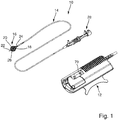
- a catheter pump 10 and a drive unit 12 for driving the catheter pump 10 is shown.
- the catheter pump 10 has a catheter 14 and at the distal end a pump head 16 for introduction into, in particular, the aorta or the heart.
- a rotor shaft is provided in the catheter 14, by means of which a conveying element 18 provided in the pump head 16, for example a rotor with fold-out propellers, can be set in rotation.
- the conveying element 18 is surrounded by a cage 20 which has a distal sleeve 22 and a proximal sleeve 24 as well as filaments 26 running between the sleeves.
- the proximal sleeve 24 is moved in the axial direction towards the distal sleeve 22.
- the catheter 14 provides an actuation section 28 via which the proximal sleeve 24 can be moved towards the distal sleeve 22. Furthermore, the actuating section 28 can be inserted into the drive unit 12, by means of which the rotor shaft, and thus the conveying element 18, can ultimately be set in rotation.
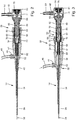
- the actuation section 28 which comprises a base part 30 and an actuation part 32 which can be moved in the axial direction relative to the base part 30.
- the catheter 14 has an outer catheter 34 and an inner catheter 36 which can be axially displaced in the outer catheter 34.
- the rotatable rotor shaft 38 is provided in the inner catheter 36.
- the outer catheter 34 is fixedly arranged with its proximal end 40 on the actuation part 32.
- the inner catheter 36 reaches through the actuation part 32 in the axial direction and is arranged with its proximal end 58 fixedly on the base part 30.
- the outer catheter 34 can consequently be moved relative to the inner catheter 36. Because the distal sleeve 22 of the cage 20 is coupled in movement to the inner catheter 36 and the proximal sleeve 24 is coupled in movement to the outer catheter in the axial direction, a relative movement of the actuating part 32 with respect to the base part 30, and thus the outer catheter 34 with respect to the inner catheter 36, the proximal sleeve 24 can be moved towards the distal sleeve 22 or away from the distal sleeve 22 for expanding the cage 20 or for collapsing or folding in the cage 20.
- the movement coupling is such that not only the cage 20, but at the same time as the cage 20, or preferably shortly thereafter, the conveying element 18 is expanded when the actuating part 32 is moved in the distal direction.
- the actuating part 32 has an inlet 44 in which a hose 46 is located, via which rinsing liquid can be pumped to the bearing points of the conveying element 18.
- a hose 46 is located, via which rinsing liquid can be pumped to the bearing points of the conveying element 18.
- rinsing liquid consequently flows, as in FIG Figure 3 shown, via the hose 46 into the inlet 44.
- an inlet space 52 connected to the inlet 44 is provided, which is connected to an inlet lumen present between the outer catheter 34 and the inner catheter 36.
- rinsing liquid can flow from the inlet space 52 via the inlet lumen to the bearing points of the conveying element 18 at the distal end of the catheter 14.
- the inlet space 52 is delimited on the proximal side by a piston section 54 of the base part 30 which is axially displaceable in the inlet space 52 and dips into the inlet space 52.
- a sealing ring 56 is provided on the piston section 54 in a circumferential groove.
- the piston section 54 also receives the proximal end 58 of the inner catheter 36. As a result, the proximal end 58 of the inner catheter 36 is connected to the piston section 54 in a movement-coupled manner in the axial direction.
- the base part 30 also has a sleeve-like bearing section 60 which forms a receiving space 62.
- a bearing sleeve 64 is accommodated in the receiving space 62, in which two pivot bearings 66 are provided which are axially spaced apart and which pivot the proximal end section 68 of the rotor shaft 38.
- the rotor shaft 38 or its end section 68 extends through the receiving space 62.
- the end section 68 of the rotor shaft 38 is designed as a rigid shaft which is connected to the flexible part of the rotor shaft 38 via a coupling section 70.
- the receiving space 62 is also connected to an outlet lumen present between the inner catheter 36 and the rotor shaft 38.
- the base part 30 has an outlet 48 connected to it Outlet space 74, which is connected to the outlet 48 or the hose 50.
- the rinsing liquid coming from the bearing points of the conveying element 18 can thus flow via the outlet lumen, the receiving space 62 and the outlet space 74 to the outlet 48 or hose 50, as indicated by the arrows in line 72.
- the rotor shaft 38 which rotates during operation, is lubricated in the inner catheter 36 and, on the other hand, the rotary bearings 66 can be adequately lubricated and cooled.
- a rotary coupling section 78 is provided at the free, proximal end 76 of the rotor shaft 38 or at its end section 68.
- the rotary coupling section 78 comprises a magnetic ring, which via a drive-side, in Figure 1 indicated magnetic ring 79 can be set in rotation via magnetic coupling.
- a further magnet can be provided on the rotor shaft 38 or on its end section 68, with which a corresponding sensor in the drive unit can be used to detect whether the shaft is rotating or not, or at what speed it is rotating.
- the base part 30 has a cap 80 at its proximal end which covers the outlet space 74 and which also contains the outlet 48.
- a cylindrical sliding receptacle 82 is provided at the proximal end of the actuating part 32 for safe guidance of the actuating part 32 with respect to the base part 30.
- the sliding receptacle 82 there is a piston-like design Slidably housed sliding portion 84 of the base part 30.
- the sliding section 84 is formed by sections of the lateral surface of the bearing section 60.
- the base part 30 and the actuating part 32 can be designed in one piece or in several pieces.
- the base part 30 consists of several individual parts, such as the piston section 54, the bearing section 60 including the bearing sleeve 64 and the cap 80.
Landscapes
- Health & Medical Sciences (AREA)
- Heart & Thoracic Surgery (AREA)
- Engineering & Computer Science (AREA)
- Life Sciences & Earth Sciences (AREA)
- Hematology (AREA)
- Public Health (AREA)
- Biomedical Technology (AREA)
- Anesthesiology (AREA)
- Veterinary Medicine (AREA)
- Animal Behavior & Ethology (AREA)
- General Health & Medical Sciences (AREA)
- Mechanical Engineering (AREA)
- Cardiology (AREA)
- Biophysics (AREA)
- Pulmonology (AREA)
- Vascular Medicine (AREA)
- External Artificial Organs (AREA)
- Media Introduction/Drainage Providing Device (AREA)
- Transplantation (AREA)
Applications Claiming Priority (2)
| Application Number | Priority Date | Filing Date | Title |
|---|---|---|---|
| DE102017102824.2A DE102017102824A1 (de) | 2017-02-13 | 2017-02-13 | Katheterpumpe mit Antriebseinheit und Katheter |
| PCT/EP2018/053131 WO2018146177A1 (de) | 2017-02-13 | 2018-02-08 | Katheterpumpe mit antriebseinheit und katheter |
Publications (2)
| Publication Number | Publication Date |
|---|---|
| EP3579904A1 EP3579904A1 (de) | 2019-12-18 |
| EP3579904B1 true EP3579904B1 (de) | 2021-11-10 |
Family
ID=61198842
Family Applications (1)
| Application Number | Title | Priority Date | Filing Date |
|---|---|---|---|
| EP18704952.3A Active EP3579904B1 (de) | 2017-02-13 | 2018-02-08 | Katheterpumpe mit antriebseinheit und katheter |
Country Status (8)
| Country | Link |
|---|---|
| US (1) | US11103690B2 (ja) |
| EP (1) | EP3579904B1 (ja) |
| JP (1) | JP6927647B2 (ja) |
| CN (1) | CN110290825B (ja) |
| DE (1) | DE102017102824A1 (ja) |
| ES (1) | ES2901020T3 (ja) |
| RU (1) | RU2733971C9 (ja) |
| WO (1) | WO2018146177A1 (ja) |
Families Citing this family (18)
| Publication number | Priority date | Publication date | Assignee | Title |
|---|---|---|---|---|
| CA3066361A1 (en) | 2017-06-07 | 2018-12-13 | Shifamed Holdings, Llc | Intravascular fluid movement devices, systems, and methods of use |
| EP3710076B1 (en) | 2017-11-13 | 2023-12-27 | Shifamed Holdings, LLC | Intravascular fluid movement devices, systems, and methods of use |
| DE102018201030A1 (de) | 2018-01-24 | 2019-07-25 | Kardion Gmbh | Magnetkuppelelement mit magnetischer Lagerungsfunktion |
| US10722631B2 (en) | 2018-02-01 | 2020-07-28 | Shifamed Holdings, Llc | Intravascular blood pumps and methods of use and manufacture |
| EP3768349A4 (en) | 2018-03-20 | 2021-12-29 | Second Heart Assist, Inc. | Circulatory assist pump |
| US11690997B2 (en) | 2018-04-06 | 2023-07-04 | Puzzle Medical Devices Inc. | Mammalian body conduit intralumenal device and lumen wall anchor assembly, components thereof and methods of implantation and explanation thereof |
| DE102018211327A1 (de) | 2018-07-10 | 2020-01-16 | Kardion Gmbh | Laufrad für ein implantierbares, vaskuläres Unterstützungssystem |
| JP2022540616A (ja) | 2019-07-12 | 2022-09-16 | シファメド・ホールディングス・エルエルシー | 血管内血液ポンプならびに製造および使用の方法 |
| US11654275B2 (en) | 2019-07-22 | 2023-05-23 | Shifamed Holdings, Llc | Intravascular blood pumps with struts and methods of use and manufacture |
| WO2021032283A1 (en) * | 2019-08-19 | 2021-02-25 | Reco2Lung Gmbh | Endovascular cannula for defining a border of a transport volume for an in-vivo fluid transport, cannula system and corresponding method |
| WO2021032282A1 (en) * | 2019-08-19 | 2021-02-25 | Reco2Lung Gmbh | Cannula comprising an expandable arrangement, corresponding cannula system and method for inserting at least one cannula into a subject |
| US20220323663A1 (en) * | 2019-08-19 | 2022-10-13 | Reco2Very Therapies Gmbh | Cannula Comprising an Expandable Arrangement, Corresponding Cannula System and Method for Inserting at Least One Cannula into a Subject |
| US11724089B2 (en) | 2019-09-25 | 2023-08-15 | Shifamed Holdings, Llc | Intravascular blood pump systems and methods of use and control thereof |
| DE102020102474A1 (de) | 2020-01-31 | 2021-08-05 | Kardion Gmbh | Pumpe zum Fördern eines Fluids und Verfahren zum Herstellen einer Pumpe |
| CN113289198B (zh) * | 2021-04-16 | 2023-05-16 | 杭州未名信科科技有限公司 | 给药导管和给药导管的制备方法 |
| CN113244525B (zh) * | 2021-05-11 | 2023-07-04 | 丰凯利医疗器械(上海)有限公司 | 一种传动支撑与分流结构及泵血导管 |
| WO2024037554A1 (zh) * | 2022-08-15 | 2024-02-22 | 心擎医疗(苏州)股份有限公司 | 导管泵 |
| CN115364337B (zh) * | 2022-09-28 | 2023-06-30 | 苏州心擎医疗技术有限公司 | 导管装置 |
Family Cites Families (23)
| Publication number | Priority date | Publication date | Assignee | Title |
|---|---|---|---|---|
| SE501215C2 (sv) * | 1992-09-02 | 1994-12-12 | Oeyvind Reitan | Kateterpump |
| US6652546B1 (en) * | 1996-07-26 | 2003-11-25 | Kensey Nash Corporation | System and method of use for revascularizing stenotic bypass grafts and other occluded blood vessels |
| US6905505B2 (en) * | 1996-07-26 | 2005-06-14 | Kensey Nash Corporation | System and method of use for agent delivery and revascularizing of grafts and vessels |
| US6331165B1 (en) * | 1996-11-25 | 2001-12-18 | Scimed Life Systems, Inc. | Biopsy instrument having irrigation and aspiration capabilities |
| AU7354400A (en) * | 1999-09-03 | 2001-04-10 | A-Med Systems, Inc. | Guidable intravascular blood pump and related methods |
| JP4731471B2 (ja) * | 2003-04-16 | 2011-07-27 | ジェネシス・テクノロジーズ・エルエルシー | 医療機器と方法 |
| US8475487B2 (en) * | 2005-04-07 | 2013-07-02 | Medrad, Inc. | Cross stream thrombectomy catheter with flexible and expandable cage |
| US9199020B2 (en) * | 2007-11-01 | 2015-12-01 | Abiomed, Inc. | Purge-free miniature rotary pump |
| US8579858B2 (en) * | 2008-06-23 | 2013-11-12 | Cardiobridge Gmbh | Catheter pump for circulatory support |
| US9242068B2 (en) * | 2008-07-17 | 2016-01-26 | Covidien Lp | Spirally conformable infusion catheter |
| EP2246078A1 (de) * | 2009-04-29 | 2010-11-03 | ECP Entwicklungsgesellschaft mbH | Wellenanordnung mit einer Welle, die innerhalb einer fluidgefüllten Hülle verläuft |
| EP2248544A1 (de) * | 2009-05-05 | 2010-11-10 | ECP Entwicklungsgesellschaft mbH | Im Durchmesser veränderbare Fluidpumpe, insbesondere für die medizinische Verwendung |
| JP5641546B2 (ja) * | 2009-05-18 | 2014-12-17 | カーディオブリッジ ゲーエムベーハー | カテーテルポンプ |
| EP2497521A1 (de) * | 2011-03-10 | 2012-09-12 | ECP Entwicklungsgesellschaft mbH | Schubvorrichtung zum axialen Einschieben eines strangförmigen, flexiblen Körpers |
| WO2015187838A1 (en) * | 2014-06-03 | 2015-12-10 | Pigott John P | Intravascular catheter with drug delivery system |
| WO2013056131A1 (en) * | 2011-10-13 | 2013-04-18 | Reichenbach Steven H | Pump and method for mixed flow blood pumping |
| EP4186557A1 (en) | 2012-07-03 | 2023-05-31 | Tc1 Llc | Motor assembly for catheter pump |
| EP2745869A1 (de) * | 2012-12-21 | 2014-06-25 | ECP Entwicklungsgesellschaft mbH | Schleusenanordnung für die Einführung eines strangförmigen Körpers, insbesondere eines Katheters, in einen Patientenkörper |
| JP6313551B2 (ja) | 2013-07-17 | 2018-04-18 | 日立オートモティブシステムズ株式会社 | 燃料ポンプの駆動制御装置 |
| US10363349B2 (en) * | 2014-04-15 | 2019-07-30 | Tc1 Llp | Heart pump providing adjustable outflow |
| WO2015160942A1 (en) * | 2014-04-15 | 2015-10-22 | Thoratec Corporation | Catheter pump with off-set motor position |
| WO2016118777A1 (en) * | 2015-01-22 | 2016-07-28 | Thoratec Corporation | Reduced rotational mass motor assembly for catheter pump |
| US9907890B2 (en) * | 2015-04-16 | 2018-03-06 | Tc1 Llc | Catheter pump with positioning brace |
-
2017
- 2017-02-13 DE DE102017102824.2A patent/DE102017102824A1/de not_active Withdrawn
-
2018
- 2018-02-08 WO PCT/EP2018/053131 patent/WO2018146177A1/de active Application Filing
- 2018-02-08 ES ES18704952T patent/ES2901020T3/es active Active
- 2018-02-08 EP EP18704952.3A patent/EP3579904B1/de active Active
- 2018-02-08 CN CN201880011279.XA patent/CN110290825B/zh active Active
- 2018-02-08 RU RU2019128562A patent/RU2733971C9/ru active
- 2018-02-08 JP JP2019543792A patent/JP6927647B2/ja active Active
- 2018-02-08 US US16/484,808 patent/US11103690B2/en active Active
Also Published As
| Publication number | Publication date |
|---|---|
| EP3579904A1 (de) | 2019-12-18 |
| BR112019016703A2 (pt) | 2020-04-07 |
| DE102017102824A1 (de) | 2018-08-16 |
| ES2901020T3 (es) | 2022-03-21 |
| CN110290825B (zh) | 2021-07-20 |
| CN110290825A (zh) | 2019-09-27 |
| WO2018146177A1 (de) | 2018-08-16 |
| RU2733971C1 (ru) | 2020-10-08 |
| JP2020507407A (ja) | 2020-03-12 |
| US11103690B2 (en) | 2021-08-31 |
| JP6927647B2 (ja) | 2021-09-01 |
| RU2733971C9 (ru) | 2021-11-25 |
| US20200000988A1 (en) | 2020-01-02 |
Similar Documents
| Publication | Publication Date | Title |
|---|---|---|
| EP3579904B1 (de) | Katheterpumpe mit antriebseinheit und katheter | |
| EP3359215B1 (de) | Pumpe, insbesondere blutpumpe | |
| EP3628344B1 (de) | Blutpumpe | |
| EP3393543B1 (de) | Katheterpumpe mit einem pumpenkopf zum einführen in das arterielle gefässsystem | |
| EP3402545B1 (de) | Katheterpumpe mit einem pumpenkopf zum einsetzen in das arterielle gefässsystem | |
| EP3216467B1 (de) | Katheter-vorrichtung | |
| EP0905379B1 (de) | Zentrifugalpumpe und Zentrifugalpumpenanordnung | |
| EP2366412B1 (de) | Katheter-Vorrichtung | |
| EP3579894A1 (de) | Katheterpumpe mit antriebseinheit und katheter | |
| DE202009018145U1 (de) | Katheterpumpe für die Unterstützung des Kreislaufs | |
| EP2298373A1 (de) | Fluidpumpe mit wenigstens einem Schaufelblatt und einer Stützeinrichtung | |
| DE102010011998A1 (de) | Fluidpumpeinrichtung | |
| WO2002066837A1 (de) | Vorrichtung zur axialen förderung von flüssigkeiten | |
| EP3141271A1 (de) | Blutpumpe, vorzugsweise zur unterstützung eines herzens |
Legal Events
| Date | Code | Title | Description |
|---|---|---|---|
| STAA | Information on the status of an ep patent application or granted ep patent |
Free format text: STATUS: UNKNOWN |
|
| STAA | Information on the status of an ep patent application or granted ep patent |
Free format text: STATUS: THE INTERNATIONAL PUBLICATION HAS BEEN MADE |
|
| PUAI | Public reference made under article 153(3) epc to a published international application that has entered the european phase |
Free format text: ORIGINAL CODE: 0009012 |
|
| STAA | Information on the status of an ep patent application or granted ep patent |
Free format text: STATUS: REQUEST FOR EXAMINATION WAS MADE |
|
| 17P | Request for examination filed |
Effective date: 20190823 |
|
| AK | Designated contracting states |
Kind code of ref document: A1 Designated state(s): AL AT BE BG CH CY CZ DE DK EE ES FI FR GB GR HR HU IE IS IT LI LT LU LV MC MK MT NL NO PL PT RO RS SE SI SK SM TR |
|
| AX | Request for extension of the european patent |
Extension state: BA ME |
|
| DAV | Request for validation of the european patent (deleted) | ||
| DAX | Request for extension of the european patent (deleted) | ||
| GRAP | Despatch of communication of intention to grant a patent |
Free format text: ORIGINAL CODE: EPIDOSNIGR1 |
|
| STAA | Information on the status of an ep patent application or granted ep patent |
Free format text: STATUS: GRANT OF PATENT IS INTENDED |
|
| RIC1 | Information provided on ipc code assigned before grant |
Ipc: A61M 60/135 20210101ALI20210219BHEP Ipc: A61M 60/205 20210101ALI20210219BHEP Ipc: A61M 25/04 20060101ALI20210219BHEP Ipc: A61M 60/829 20210101ALI20210219BHEP Ipc: A61M 25/00 20060101AFI20210219BHEP |
|
| INTG | Intention to grant announced |
Effective date: 20210311 |
|
| GRAJ | Information related to disapproval of communication of intention to grant by the applicant or resumption of examination proceedings by the epo deleted |
Free format text: ORIGINAL CODE: EPIDOSDIGR1 |
|
| STAA | Information on the status of an ep patent application or granted ep patent |
Free format text: STATUS: REQUEST FOR EXAMINATION WAS MADE |
|
| INTC | Intention to grant announced (deleted) | ||
| GRAP | Despatch of communication of intention to grant a patent |
Free format text: ORIGINAL CODE: EPIDOSNIGR1 |
|
| STAA | Information on the status of an ep patent application or granted ep patent |
Free format text: STATUS: GRANT OF PATENT IS INTENDED |
|
| INTG | Intention to grant announced |
Effective date: 20210607 |
|
| GRAS | Grant fee paid |
Free format text: ORIGINAL CODE: EPIDOSNIGR3 |
|
| GRAA | (expected) grant |
Free format text: ORIGINAL CODE: 0009210 |
|
| STAA | Information on the status of an ep patent application or granted ep patent |
Free format text: STATUS: THE PATENT HAS BEEN GRANTED |
|
| AK | Designated contracting states |
Kind code of ref document: B1 Designated state(s): AL AT BE BG CH CY CZ DE DK EE ES FI FR GB GR HR HU IE IS IT LI LT LU LV MC MK MT NL NO PL PT RO RS SE SI SK SM TR |
|
| REG | Reference to a national code |
Ref country code: GB Ref legal event code: FG4D Free format text: NOT ENGLISH |
|
| REG | Reference to a national code |
Ref country code: AT Ref legal event code: REF Ref document number: 1445495 Country of ref document: AT Kind code of ref document: T Effective date: 20211115 Ref country code: CH Ref legal event code: EP |
|
| REG | Reference to a national code |
Ref country code: DE Ref legal event code: R096 Ref document number: 502018007764 Country of ref document: DE |
|
| REG | Reference to a national code |
Ref country code: IE Ref legal event code: FG4D Free format text: LANGUAGE OF EP DOCUMENT: GERMAN |
|
| REG | Reference to a national code |
Ref country code: LT Ref legal event code: MG9D |
|
| REG | Reference to a national code |
Ref country code: NL Ref legal event code: MP Effective date: 20211110 |
|
| REG | Reference to a national code |
Ref country code: ES Ref legal event code: FG2A Ref document number: 2901020 Country of ref document: ES Kind code of ref document: T3 Effective date: 20220321 |
|
| PG25 | Lapsed in a contracting state [announced via postgrant information from national office to epo] |
Ref country code: RS Free format text: LAPSE BECAUSE OF FAILURE TO SUBMIT A TRANSLATION OF THE DESCRIPTION OR TO PAY THE FEE WITHIN THE PRESCRIBED TIME-LIMIT Effective date: 20211110 Ref country code: LT Free format text: LAPSE BECAUSE OF FAILURE TO SUBMIT A TRANSLATION OF THE DESCRIPTION OR TO PAY THE FEE WITHIN THE PRESCRIBED TIME-LIMIT Effective date: 20211110 Ref country code: FI Free format text: LAPSE BECAUSE OF FAILURE TO SUBMIT A TRANSLATION OF THE DESCRIPTION OR TO PAY THE FEE WITHIN THE PRESCRIBED TIME-LIMIT Effective date: 20211110 Ref country code: BG Free format text: LAPSE BECAUSE OF FAILURE TO SUBMIT A TRANSLATION OF THE DESCRIPTION OR TO PAY THE FEE WITHIN THE PRESCRIBED TIME-LIMIT Effective date: 20220210 |
|
| PG25 | Lapsed in a contracting state [announced via postgrant information from national office to epo] |
Ref country code: IS Free format text: LAPSE BECAUSE OF FAILURE TO SUBMIT A TRANSLATION OF THE DESCRIPTION OR TO PAY THE FEE WITHIN THE PRESCRIBED TIME-LIMIT Effective date: 20220310 Ref country code: SE Free format text: LAPSE BECAUSE OF FAILURE TO SUBMIT A TRANSLATION OF THE DESCRIPTION OR TO PAY THE FEE WITHIN THE PRESCRIBED TIME-LIMIT Effective date: 20211110 Ref country code: PT Free format text: LAPSE BECAUSE OF FAILURE TO SUBMIT A TRANSLATION OF THE DESCRIPTION OR TO PAY THE FEE WITHIN THE PRESCRIBED TIME-LIMIT Effective date: 20220310 Ref country code: PL Free format text: LAPSE BECAUSE OF FAILURE TO SUBMIT A TRANSLATION OF THE DESCRIPTION OR TO PAY THE FEE WITHIN THE PRESCRIBED TIME-LIMIT Effective date: 20211110 Ref country code: NO Free format text: LAPSE BECAUSE OF FAILURE TO SUBMIT A TRANSLATION OF THE DESCRIPTION OR TO PAY THE FEE WITHIN THE PRESCRIBED TIME-LIMIT Effective date: 20220210 Ref country code: NL Free format text: LAPSE BECAUSE OF FAILURE TO SUBMIT A TRANSLATION OF THE DESCRIPTION OR TO PAY THE FEE WITHIN THE PRESCRIBED TIME-LIMIT Effective date: 20211110 Ref country code: LV Free format text: LAPSE BECAUSE OF FAILURE TO SUBMIT A TRANSLATION OF THE DESCRIPTION OR TO PAY THE FEE WITHIN THE PRESCRIBED TIME-LIMIT Effective date: 20211110 Ref country code: HR Free format text: LAPSE BECAUSE OF FAILURE TO SUBMIT A TRANSLATION OF THE DESCRIPTION OR TO PAY THE FEE WITHIN THE PRESCRIBED TIME-LIMIT Effective date: 20211110 Ref country code: GR Free format text: LAPSE BECAUSE OF FAILURE TO SUBMIT A TRANSLATION OF THE DESCRIPTION OR TO PAY THE FEE WITHIN THE PRESCRIBED TIME-LIMIT Effective date: 20220211 |
|
| PG25 | Lapsed in a contracting state [announced via postgrant information from national office to epo] |
Ref country code: SM Free format text: LAPSE BECAUSE OF FAILURE TO SUBMIT A TRANSLATION OF THE DESCRIPTION OR TO PAY THE FEE WITHIN THE PRESCRIBED TIME-LIMIT Effective date: 20211110 Ref country code: SK Free format text: LAPSE BECAUSE OF FAILURE TO SUBMIT A TRANSLATION OF THE DESCRIPTION OR TO PAY THE FEE WITHIN THE PRESCRIBED TIME-LIMIT Effective date: 20211110 Ref country code: RO Free format text: LAPSE BECAUSE OF FAILURE TO SUBMIT A TRANSLATION OF THE DESCRIPTION OR TO PAY THE FEE WITHIN THE PRESCRIBED TIME-LIMIT Effective date: 20211110 Ref country code: EE Free format text: LAPSE BECAUSE OF FAILURE TO SUBMIT A TRANSLATION OF THE DESCRIPTION OR TO PAY THE FEE WITHIN THE PRESCRIBED TIME-LIMIT Effective date: 20211110 Ref country code: DK Free format text: LAPSE BECAUSE OF FAILURE TO SUBMIT A TRANSLATION OF THE DESCRIPTION OR TO PAY THE FEE WITHIN THE PRESCRIBED TIME-LIMIT Effective date: 20211110 Ref country code: CZ Free format text: LAPSE BECAUSE OF FAILURE TO SUBMIT A TRANSLATION OF THE DESCRIPTION OR TO PAY THE FEE WITHIN THE PRESCRIBED TIME-LIMIT Effective date: 20211110 |
|
| REG | Reference to a national code |
Ref country code: DE Ref legal event code: R097 Ref document number: 502018007764 Country of ref document: DE |
|
| PLBE | No opposition filed within time limit |
Free format text: ORIGINAL CODE: 0009261 |
|
| STAA | Information on the status of an ep patent application or granted ep patent |
Free format text: STATUS: NO OPPOSITION FILED WITHIN TIME LIMIT |
|
| PG25 | Lapsed in a contracting state [announced via postgrant information from national office to epo] |
Ref country code: MC Free format text: LAPSE BECAUSE OF FAILURE TO SUBMIT A TRANSLATION OF THE DESCRIPTION OR TO PAY THE FEE WITHIN THE PRESCRIBED TIME-LIMIT Effective date: 20211110 |
|
| 26N | No opposition filed |
Effective date: 20220811 |
|
| REG | Reference to a national code |
Ref country code: BE Ref legal event code: MM Effective date: 20220228 |
|
| PG25 | Lapsed in a contracting state [announced via postgrant information from national office to epo] |
Ref country code: LU Free format text: LAPSE BECAUSE OF NON-PAYMENT OF DUE FEES Effective date: 20220208 Ref country code: AL Free format text: LAPSE BECAUSE OF FAILURE TO SUBMIT A TRANSLATION OF THE DESCRIPTION OR TO PAY THE FEE WITHIN THE PRESCRIBED TIME-LIMIT Effective date: 20211110 |
|
| PG25 | Lapsed in a contracting state [announced via postgrant information from national office to epo] |
Ref country code: SI Free format text: LAPSE BECAUSE OF FAILURE TO SUBMIT A TRANSLATION OF THE DESCRIPTION OR TO PAY THE FEE WITHIN THE PRESCRIBED TIME-LIMIT Effective date: 20211110 |
|
| PG25 | Lapsed in a contracting state [announced via postgrant information from national office to epo] |
Ref country code: IE Free format text: LAPSE BECAUSE OF NON-PAYMENT OF DUE FEES Effective date: 20220208 |
|
| PG25 | Lapsed in a contracting state [announced via postgrant information from national office to epo] |
Ref country code: BE Free format text: LAPSE BECAUSE OF NON-PAYMENT OF DUE FEES Effective date: 20220228 |
|
| PGFP | Annual fee paid to national office [announced via postgrant information from national office to epo] |
Ref country code: FR Payment date: 20230217 Year of fee payment: 6 |
|
| PGFP | Annual fee paid to national office [announced via postgrant information from national office to epo] |
Ref country code: TR Payment date: 20230207 Year of fee payment: 6 Ref country code: IT Payment date: 20230228 Year of fee payment: 6 |
|
| P01 | Opt-out of the competence of the unified patent court (upc) registered |
Effective date: 20230601 |
|
| PGFP | Annual fee paid to national office [announced via postgrant information from national office to epo] |
Ref country code: DE Payment date: 20230412 Year of fee payment: 6 |
|
| REG | Reference to a national code |
Ref country code: AT Ref legal event code: MM01 Ref document number: 1445495 Country of ref document: AT Kind code of ref document: T Effective date: 20230208 |
|
| PGFP | Annual fee paid to national office [announced via postgrant information from national office to epo] |
Ref country code: ES Payment date: 20240319 Year of fee payment: 7 |
|
| PG25 | Lapsed in a contracting state [announced via postgrant information from national office to epo] |
Ref country code: AT Free format text: LAPSE BECAUSE OF NON-PAYMENT OF DUE FEES Effective date: 20230208 |
|
| PG25 | Lapsed in a contracting state [announced via postgrant information from national office to epo] |
Ref country code: MK Free format text: LAPSE BECAUSE OF FAILURE TO SUBMIT A TRANSLATION OF THE DESCRIPTION OR TO PAY THE FEE WITHIN THE PRESCRIBED TIME-LIMIT Effective date: 20211110 Ref country code: CY Free format text: LAPSE BECAUSE OF FAILURE TO SUBMIT A TRANSLATION OF THE DESCRIPTION OR TO PAY THE FEE WITHIN THE PRESCRIBED TIME-LIMIT Effective date: 20211110 Ref country code: AT Free format text: LAPSE BECAUSE OF NON-PAYMENT OF DUE FEES Effective date: 20230208 |
|
| PGFP | Annual fee paid to national office [announced via postgrant information from national office to epo] |
Ref country code: GB Payment date: 20240213 Year of fee payment: 7 Ref country code: CH Payment date: 20240301 Year of fee payment: 7 |