EP3579786B1 - Zahnärztliche lichtbestrahlungsvorrichtung - Google Patents
Zahnärztliche lichtbestrahlungsvorrichtung Download PDFInfo
- Publication number
- EP3579786B1 EP3579786B1 EP18704853.3A EP18704853A EP3579786B1 EP 3579786 B1 EP3579786 B1 EP 3579786B1 EP 18704853 A EP18704853 A EP 18704853A EP 3579786 B1 EP3579786 B1 EP 3579786B1
- Authority
- EP
- European Patent Office
- Prior art keywords
- camera
- irradiation device
- light irradiation
- detector
- instruction
- Prior art date
- Legal status (The legal status is an assumption and is not a legal conclusion. Google has not performed a legal analysis and makes no representation as to the accuracy of the status listed.)
- Active
Links
Images

Classifications
-
- A—HUMAN NECESSITIES
- A61—MEDICAL OR VETERINARY SCIENCE; HYGIENE
- A61C—DENTISTRY; APPARATUS OR METHODS FOR ORAL OR DENTAL HYGIENE
- A61C19/00—Dental auxiliary appliances
- A61C19/003—Apparatus for curing resins by radiation
- A61C19/004—Hand-held apparatus, e.g. guns
-
- G—PHYSICS
- G03—PHOTOGRAPHY; CINEMATOGRAPHY; ANALOGOUS TECHNIQUES USING WAVES OTHER THAN OPTICAL WAVES; ELECTROGRAPHY; HOLOGRAPHY
- G03B—APPARATUS OR ARRANGEMENTS FOR TAKING PHOTOGRAPHS OR FOR PROJECTING OR VIEWING THEM; APPARATUS OR ARRANGEMENTS EMPLOYING ANALOGOUS TECHNIQUES USING WAVES OTHER THAN OPTICAL WAVES; ACCESSORIES THEREFOR
- G03B15/00—Special procedures for taking photographs; Apparatus therefor
- G03B15/02—Illuminating scene
- G03B15/03—Combinations of cameras with lighting apparatus; Flash units
-
- G—PHYSICS
- G03—PHOTOGRAPHY; CINEMATOGRAPHY; ANALOGOUS TECHNIQUES USING WAVES OTHER THAN OPTICAL WAVES; ELECTROGRAPHY; HOLOGRAPHY
- G03B—APPARATUS OR ARRANGEMENTS FOR TAKING PHOTOGRAPHS OR FOR PROJECTING OR VIEWING THEM; APPARATUS OR ARRANGEMENTS EMPLOYING ANALOGOUS TECHNIQUES USING WAVES OTHER THAN OPTICAL WAVES; ACCESSORIES THEREFOR
- G03B15/00—Special procedures for taking photographs; Apparatus therefor
- G03B15/14—Special procedures for taking photographs; Apparatus therefor for taking photographs during medical operations
-
- A—HUMAN NECESSITIES
- A61—MEDICAL OR VETERINARY SCIENCE; HYGIENE
- A61C—DENTISTRY; APPARATUS OR METHODS FOR ORAL OR DENTAL HYGIENE
- A61C2204/00—Features not otherwise provided for
- A61C2204/002—Features not otherwise provided for using batteries
Definitions
- the invention relates to a dental light irradiation device that has a first light source for emitting blue light, a camera and at least a first detector.
- the device of the invention is operable in a sleep mode, a non-camera mode and in a camera mode, and the camera mode can be activated only in the non-camera mode.
- Light hardenable or light curable materials are widely used in dentistry for the restoration of teeth. Many of such materials are made to provide optical instructions that resemble those of natural teeth. Further such materials typically can be placed precisely and conveniently, can be hardened instantly, and the hardened material is typically relatively durable. Accordingly these materials are favored alternatives to less pleasant looking and over time self-hardening materials, like for example amalgam.
- Light hardenable materials often include a polymerizable matrix material and filler materials including colorants, and may initially be generally soft or flowable so that they can be applied in a desired location and shape.
- the dental material may be filled into a tooth cavity and shaped so that the restored tooth resembles a natural tooth.
- the material may be cured by exposing it to light of a desired wavelength. The light typically activates photoinitiators in the dental material that cause the matrix material to polymerize.
- WO 2014/043488 discloses a dental irradiation device having a first light emitting unit for emitting blue light for light hardening of a dental material and second light emitting unit.
- the device further has an image sensing unit.
- the device can be used for simultaneous illumination and image capturing.
- US 2015/250572 A1 discloses a visualization of an area sensed by an image sensing unit.
- the visualization includes displaying the images real time on a computer screen.
- the invention relates to a dental light irradiation device according to claim 1.
- the dental light irradiation device comprises a first light source for emitting blue light, a camera and at least a first detector.
- the device is operable in a camera mode in which the camera is activated and in a non-camera mode in which the camera is deactivated. Further, in the non-camera mode a user input on the first detector activates the camera mode.
- the invention is advantageous in that it provides a dental light irradiation device which provides functions for curing a light hardenable dental material in both, the non-camera mode and the camera mode.
- the present invention enables the visualization in both the non-camera mode and the camera mode.
- the device helps maximizing the user comfort in that the camera mode is entirely optional.
- the dental light irradiation device can nevertheless be used for curing dental materials without restrictions.
- a user input on a detector depends on the type of detector used in the dental light irradiation device.
- a touch sensor a user input corresponds to touching and releasing the touch sensor.
- a push button a user input corresponds to pushing and releasing the push button.
- the user input may comprise touching/pushing and releasing the touch sensor/push button one or more times (for example double push/release).
- Other sensors are possible, like for example a voice sensor. In the following it may be referred to a push button to simplify explanation although other types of detectors may be likewise used.
- blue light refers to light having a wavelength within the range of about 430 nm to 500 nm, preferably within a range of about 430 nm to 480 nm. Blue light preferably predominantly consists of light within a range of about 430 nm to 480 nm. The blue light may particularly not comprise light having a wavelength outside the range of about 430 nm to 480 nm at a substantial intensity or at all.
- blue light may have a first portion of light within a range of about 430 nm to 480 nm and preferably does not have a significant second light portion within a range of 570 nm and 590 nm, wherein the maximum intensity of the second portion of light is preferably less than 10% and more preferably less than 1% of the maximum intensity of the first portion of light.
- Further blue light may not have a significant third light portion within the spectrum of visible light outside the range of 430 nm and 480 nm and outside the range of 570 nm to 590 nm, wherein the maximum intensity of any third portion of light is preferably less than 25% and more preferably less than 20% of the maximum intensity of the first portion of light.
- white light refers to light having a wavelength within a range of about 380 nm to 780 nm. Although white light may also comprise light at wavelengths overlapping with the range of wavelengths of blue light, the white light preferably does not predominantly consist of light within that range but has significant portions of visible light at wavelengths outside that range.
- Any user input may represent an instruction that can be recognized by the device.
- the duration of the user input for example the duration of the time between the push and next release of a button may be interpreted as a particular instruction.
- the dental light irradiation device therefore preferably comprises electronic circuitry that is configured to execute a program by which user inputs can be evaluated for the presence of any instruction.
- the light device preferably has a memory in which different user inputs are assigned to particular instructions.
- the camera mode has a default operation in which the dental light irradiation device transmits images captured by the camera to a receiving external device at real time (or live), preferably to a display or to a device that provides a display.
- a receiving external device may be a tablet or other computer with a display, for example.
- the dental light irradiation device is set up to fall back to in the default real-time operation in case no other operation under the camera mode is activated.
- a detection of a "freeze image” instruction of the user input via the first detector triggers a freeze of an image captured by the camera.
- the freeze of the image may be performed in that the image that the camera captures at the moment at which the "freeze image” instruction is recognized is stored in the device and in that the stored image is continuously transmitted to the external device instead of transmitting the real-time or live image.
- the dental light irradiation device forwards the "freeze image” instruction or sends a new "freeze image” instruction to the external device and the external device manages the display of the frozen image at its end.
- a detection of a "camera-off" instruction of the user input via the first detector causes the device to switch in the non-camera mode.
- the dental light irradiation device further comprises a sleep mode.
- the sleep mode the camera and the first light source are deactivated.
- the non-camera mode is preferably activated by waking up the device from the sleep mode. This means that the dental light irradiation device preferably wakes up in the non-camera mode in which the camera is deactivated and that the dental light irradiation device must be switched into the camera mode by the user.
- the dental light irradiation device comprises a gyro sensor that in the sleep mode monitors an acceleration of the device and causes the non-camera mode to activate upon sensing an acceleration.
- the dental light irradiation device may activate the non-camera mode if a sensed acceleration exceeds a predetermined threshold value.
- the dental light irradiation device further comprises a second detector.
- the second detector is preferably provided for controlling operations of the first light source.
- a user input on the second detector activates a cure operation of the dental light irradiation device.
- the first light source is activated or switched on.
- the cure operation preferably comprises at least a default cure operation and a tack cure operation.
- a detection of a "start cure” instruction of the user input via the second detector preferably activates the default cure operation
- a detection of a "tack cure” instruction of the user input via the second detector preferably activates the tack cure operation.
- the first light source is automatically activated for a pre-determined first time period after which the first light source is automatically deactivated.
- the first light source is preferably automatically activated for a pre-determined second time period after which the first light source is automatically deactivated.
- the term "automatically” means that the first light source is activated by control of the dental light irradiation device in consequence of recognizing the associated instruction from the user input.
- the second time period is preferably shorter than the first time period.
- the first time period may be selectable between at least 5, 10, 15 and 20 seconds, and the second time period may be 1 or about 1 second.
- the dental light irradiation device further comprises a third detector for adjusting or pre-selecting the first time period.
- the first, second and the third detector each are formed by or comprise at least one push button or touch sensor.
- Each of the first, second and third detector may be a first, second and third push button, respectively or a first, second and third sensor, respectively.
- the dental light irradiation device may comprise three buttons which form the first, second and third detector.
- the second detector may comprise two push buttons or two touch sensors arranged on opposite sides of the dental light irradiation device.
- the dental light irradiation device comprises four buttons, and two of the four buttons form the second detector.
- a user input may be provided on either one or both of the two buttons that form the second detector. For example, a user input may be provided on only one of the two buttons.
- the dental light irradiation device if used in a patient's mouth.
- one of the sensors/buttons is oriented (and thus visible) to a user regardless of whether the device is used for curing a dental material in a tooth in the upper or in the lower jaw of the patient.
- a dental light irradiation device that comprises a first light source for emitting blue light and a detector that comprises two push buttons or two touch sensors arranged on opposite sides of the dental light irradiation device.
- a dental light irradiation device may not have a camera and a first detector.
- the "start cure” and the “tack cure” instruction are each based on a duration for which a user input is maintained on the second detector, wherein the "start cure” instruction is associated to a first duration and the “tack cure” instruction is associated to a different second duration.
- a detection of a "video start” instruction of the user input via the first detector triggers the recording of a video via the camera.
- the "video start” instruction is preferably only enabled while the dental light irradiation device is operating in the default real-time operation.
- the "video start” instruction may be characterized by a double push and release on the first push button within a predetermined time, for example with 1 second.
- a detection of a "video stop” instruction of the user input via the first detector preferably triggers the recording of the video to stop.
- the "video stop” instruction may be characterized by any further user input on the first detector.
- a detection of a "camera-off" instruction of the user input via the first detector causes the device to switch in the non-camera mode.
- the "camera-off' instruction is preferably only enabled while the dental light irradiation device is operating in the default real-time operation.
- the dental light irradiation device may have the first detector, optionally the third detector but not the second detector.
- the device may only have two buttons. One of the two buttons may have multiple functions for switching between the camera.
- a detection of a "camera-on" instruction of the user input via the first detector activates the camera mode
- the detection of a "start cure” instruction of the user input via the first detector activates a cure operation of the dental light irradiation device, wherein in the cure operation the first light source is activated.
- the camera function and the function of the first light source are controlled via operation of the same first detector. This allows for minimizing the amount of detectors in the device.
- the dental light irradiation device further comprises a second light source for emitting white light.
- the second light source may be activated in association with an activation of the camera.
- the second light source may be activated simultaneously with the activation of the camera by control of the dental light irradiation device. Further, in the sleep mode the camera and the first and second light source are deactivated.
- first and second light source and the camera are arranged adjacent each other and adjacent an end of an intra-oral tip of the dental light irradiation device.
- first and second light source may be arranged in the end of the intra-oral tip.
- the first light source may comprise one or more blue LEDs (Light Emitting Diodes) that are arranged in a periphery around the camera.
- the second light source may comprise one or more white LEDs (Light Emitting Diodes) that are also arranged in a periphery around the camera.
- the white and blue LEDs may be arranged circumferentially in an alternate fashion.
- the dental light irradiation device comprising a wireless communication interface for transmitting image data captured by the camera to a wireless network.
- the wireless data transmission may be based on standards like BluetoothTM or IEEE 802.11 standards. It is however possible, to provide a dental light irradiation device which has a wired interface for wire-based data transfer. Preferably the data transmission is enabled in the camera mode only. Thus, if the dental light irradiation device is used in the non-camera mode battery power for the communication interface can be saved.
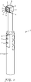
- Fig. 1 shows a dental light irradiation device 1.
- the dental light irradiation device 1 has a camera 2, a first light source 3 for emitting blue light and a second light source 4 for emitting white light.
- the first light source 3 comprises a plurality of blue LEDs (Light Emitting Diodes), but may in another example be formed of a single blue LED.
- the second light source 4 comprises a plurality of white LEDs. Again, alternatively the second light source 4 may be formed of a single white LED.
- the camera 2 may be a CCD or CMOS based camera, or may be based on any other appropriate technology.
- the camera 2 as well as the first and second light source 3, 4 are accommodated in a tip portion 5 of the dental light irradiation device 1.
- the camera, the first and/or the second light source may be accommodated in a handle portion 6 of the dental light irradiation device 1 with (an) associated light guide(s) extending between the tip portion 5 and the camera, the first and/or the second light source.
- the dental light irradiation device 1 in the example is an overall wireless device, but may in another example be wired.
- the light irradiation device 1 has a rechargeable battery (not visible).
- a charging device may be provided (not shown) by which the battery can be charged.
- the light irradiation device 1 may be connected to the charging device in a contactless manner or by electrical contact-based connection.
- the dental light irradiation device 1 has a first, second and third detector for operation the device 1 as described in the following.
- the first, second and third detector are provided in the form of a first, second and third push button.
- the dental light irradiation device 1 has a gyro sensor (not visible) for monitoring a movement or acceleration of the device 1 and for initiating operations of the device as described in the following.
- Fig. 2 shows a flowchart illustrating the function of the dental light irradiation device.
- the dental light irradiation device is basically operable in two alternative modes, namely a camera mode C and a non-camera mode N.
- the dental light irradiation device can operate in a sleep mode S.
- the dental light irradiation device In the sleep mode S generally the camera and the first and second light source are deactivated.
- the dental light irradiation device automatically activates the sleep mode S if no user input is detected via the first, second and third detector for a predetermined idle time period, for example of 5 minutes (S4). Other time periods may be predetermined as appropriate.
- the dental light irradiation device preferably activates the sleep mode S if, in addition to the absence of any user input on the first, second and/or third detector, the gyro sensor does not sense any motion or acceleration of the device within the predetermined idle time period (S1).
- the dental light irradiation device is set up to preferably immediately switch into the sleep mode upon connecting the device to a charging unit (S5).
- a charging unit is connected and recognized by the device an automatic charging program is activated which checks the charge state of the battery and charges the battery dependent thereon.
- the device is in the sleep mode S the device is waked up in case one of the following incidents occur:
- N0 in the flowchart designates an idle operation of the dental light irradiation device.
- the camera and the first and second light source are deactivated.
- the first, second and third detectors are monitored for a user input.
- the curing time preselection operation N1 in the flowchart designates a curing time preselection operation for adjusting a first time period.
- the first time period is the time period for which the first light source is automatically activated and after which the first light source is automatically deactivated.
- the curing time preselection operation N1 is activated in case a user input is detected on the third detector.
- Each user input (N11) on the third detector for example each push and release on the third push button, may increase (N12) the first time period by a certain time increment, for example 5 seconds.
- a further user input on the third detector preferably causes the first time period to be reset on a minimum time period (for example 5 seconds).
- the dental light irradiation device automatically returns in the idle operation N0 once the curing time preselection operation N1 ends.
- N2 designates a default cure operation.
- the device evaluates that user input for a presence of a "start cure” instruction.
- the "start cure” instruction in the example is characterized by a duration between a push and the next release of the second push button that is below a predetermined time, in the example below one second. This means that the "start cure” instruction is recognized in case the duration of the user input is shorter than one second.
- the device activates the default cure mode in which the first light source is activated (N22) for the first time period.
- the operation of the first light source may be interrupted (N23) in case a further user input is detected on the second detector. Otherwise the first light source is automatically deactivated after lapse of the first time period (N24).
- the dental light irradiation device automatically returns in the idle operation N0 once the default cure operation N2 ends.
- N3 designates a tack cure operation.
- the device further evaluates that user input for a presence of a "tack cure” instruction.
- the "tack cure” instruction in the example is characterized by a duration between a push and the next release of the second push button that exceeds a predetermined time, in the example reaches one second or more. This means that the "tack cure” instruction is recognized in case the user input lasts one second or more.
- the device activates the tack cure mode in which the first light source is activated (N32) for one second before the first light source is automatically switched off.
- the dental light irradiation device automatically returns in the idle operation N0 once the tack cure operation N3 ends.
- N4 designates the activation of the camera mode.
- the device In case a user input of the first detector, for example a push and release on the first push button, is detected (C41) the device is activated in the camera mode C in which the camera is switched on.
- the camera mode C operates in a real-time camera operation (C0) in which images captured by the camera are transmitted real-time to a display, for example a computer screen or tablet.
- the image transmission is preferably performed by a wireless data transmission.
- the camera mode provides several operations C0, C1, C2, C3, C4, C5 and C6 of the device that can be selectively activated under the camera mode.
- C1, C2, and C3 are identical to the operations N1, N2 and N3, respectively, although in C1 to C3 the camera is activated while in N1 to N3 the camera is deactivated.
- C11, C12 which is identical to N11, N12, respectively.
- C21, C22, C23, C24 is identical to N21, N22, N23, N24, respectively
- C31, C32 is identical to N31, N32, respectively.
- C4 designates an image capturing operation.
- a user input is detected on the first detector that user input is evaluated for the presence of a "freeze image” instruction (C41).
- the "freeze image” instruction is characterized by a duration between a push and the next release of the first push button that is shorter than one second.
- the device is switched in an image freeze operation C42.
- the image freeze operation the image displayed at the moment at which the "freeze image” instruction was recognized is frozen. For example, the transmission of the image captured at the moment the "freeze image” instruction was recognized may be maintained (while the transmission of the real-time image is suspended).
- the device switches either back to the real-time camera operation C0 or to a snapshot operation C43 in which a photo of the frozen image is stored, depending on the input instruction recognized from the user input.
- the input instruction is characterized by a push and release on the first push button for a duration of below one second (C421)
- the device switches back to the real-time camera operation C0.
- the snapshot operation C43 is activated. Once the photo is taken and stored the snapshot operation automatically finishes and the device returns to the real-time camera mode C0.
- C5 designates an optional video operation.
- a user input is detected on the first detector that user input is evaluated for the presence of a "video start” instruction (C51).
- the "video start” instruction is characterized by a double push and release on the first push button (similar to a double click on a computer).
- the recognition of the "video start” instruction triggers the recording of a video from the images captured by the camera (C52).
- the recording stops as soon as a further user input is detected (C53) on the first detector.
- the device returns to the real-time camera mode C0 automatically after.
- C6 designates a camera off operation.
- a user input is detected on the first detector that user input is evaluated for the presence of a "camera-off” instruction (C61).
- the "camera-off” instruction is characterized by a duration between a push and release of the first push button of more than three seconds.
- the switching between the camera mode and the non-camera mode is disabled.
- most preferably during the execution of the default cure operation C2 in the camera mode switching to the non-camera mode is disabled. This means that an operation of the first detector during the execution of the default cure mode does not have any effect. Thus, it can be prevented that a user, for example a dentist, switches the to the non-camera mode while monitoring the curing of a dental material in a patient's mouth on a display.
Landscapes
- Health & Medical Sciences (AREA)
- Physics & Mathematics (AREA)
- General Physics & Mathematics (AREA)
- Oral & Maxillofacial Surgery (AREA)
- Dentistry (AREA)
- Epidemiology (AREA)
- Life Sciences & Earth Sciences (AREA)
- Animal Behavior & Ethology (AREA)
- General Health & Medical Sciences (AREA)
- Public Health (AREA)
- Veterinary Medicine (AREA)
- Dental Tools And Instruments Or Auxiliary Dental Instruments (AREA)
Claims (13)
- Eine zahnärztliche Lichtbestrahlungsvorrichtung (1), aufweisend eine erste Lichtquelle (3) zum Emittieren von blauem Licht, eine Kamera (2) und mindestens einen ersten Detektor, wobei die Vorrichtung in einem Kameramodus (C), in dem die Kamera aktiviert ist, und in einem Nichtkameramodus (N), in dem die Kamera deaktiviert ist, betreibbar ist, wobei eine Benutzereingabe an dem ersten Detektor in dem Nichtkameramodus (N) den Kameramodus (C) aktiviert, wobei eine Detektion einer Anweisung "Bild einfrieren" der Benutzereingabe über den ersten Detektor in dem Kameramodus (C) ein Einfrieren eines durch die Kamera (2) aufgenommenen Bildes auslöst und eine Detektion einer Anweisung "Kamera aus" der Benutzereingabe über den ersten Detektor bewirkt, dass die Vorrichtung (1) in den Nichtkameramodus (N) umschaltet.
- Die zahnärztliche Lichtbestrahlungsvorrichtung nach Anspruch 1, ferner aufweisend einen Schlafmodus (S), in dem die Kamera (2) und die erste Lichtquelle (3) deaktiviert sind, wobei der Nichtkameramodus (N) durch Aufwecken der Vorrichtung (1) aus dem Schlafmodus (S) aktiviert wird.
- Die zahnärztliche Lichtbestrahlungsvorrichtung (1) nach Anspruch 2, ferner aufweisend einen Gyrosensor, der eine Beschleunigung der Vorrichtung (1) in dem Schlafmodus (S) überwacht und bewirkt, dass der Nichtkameramodus (N) beim Erfassen einer Beschleunigung aktiviert wird.
- Die zahnärztliche Lichtbestrahlungsvorrichtung (1) nach einem der vorstehenden Ansprüche, ferner aufweisend einen zweiten Detektor, wobei entweder in dem Nichtkameramodus (N) oder dem Kameramodus (C) eine Benutzereingabe an dem zweiten Detektor einen Härtungsbetrieb der zahnärztlichen Lichtbestrahlungsvorrichtung aktiviert, wobei die erste Lichtquelle in dem Härtungsbetrieb aktiviert wird.
- Die zahnärztliche Lichtbestrahlungsvorrichtung nach Anspruch 4, wobei der Härtungsbetrieb zumindest einen Standard-Härtungsbetrieb und einen Klebe-Härtungsbetrieb aufweist, wobei entweder in dem Nichtkameramodus (N) oder dem Kameramodus (C) eine Detektion einer Anweisung "Härten starten" der Benutzereingabe über den zweiten Detektor den Standard-Härtungsbetrieb aktiviert, und eine Detektion einer Anweisung "Klebehärtung" der Benutzereingabe über den zweiten Detektor den Klebe-Härtungsbetrieb aktiviert, wobei die erste Lichtquelle in dem Standard-Härtungsbetrieb automatisch einen vorbestimmten ersten Zeitraum lang aktiviert wird, nach dem die erste Lichtquelle automatisch deaktiviert wird, und wobei die erste Lichtquelle in dem Klebe-Härtungsbetrieb automatisch einen vorbestimmten zweiten Zeitraum lang aktiviert wird, nach dem die erste Lichtquelle automatisch deaktiviert wird, und wobei der zweite Zeitraum kürzer als der erste Zeitraum ist.
- Die zahnärztliche Lichtbestrahlungsvorrichtung nach Anspruch 5, ferner aufweisend einen dritten Detektor zum Einstellen oder Vorauswählen des ersten Zeitraums.
- Die zahnärztliche Lichtbestrahlungsvorrichtung nach Anspruch 6, wobei der erste und der dritte Detektor jeweils mindestens eine Drucktaste oder einen Berührungssensor aufweisen, und wobei der zweite Detektor zwei Drucktasten oder zwei Berührungssensoren aufweist, die auf gegenüberliegenden Seiten der zahnärztlichen Lichtbestrahlungsvorrichtung angeordnet sind.
- Die zahnärztliche Lichtbestrahlungsvorrichtung nach einem der Ansprüche 5 bis 7, wobei die Anweisung "Härten starten" und die Anweisung "Klebehärten" jeweils auf einer Dauer basieren, während der eine Benutzereingabe an dem zweiten Detektor aufrechterhalten wird, wobei die Anweisung "Härten starten" einer ersten Dauer zugeordnet ist und die Anweisung "Klebehärten" einer anderen, zweiten Dauer zugeordnet ist.
- Die zahnärztliche Lichtbestrahlungsvorrichtung nach einem der vorstehenden Ansprüche, wobei eine Detektion einer Anweisung "Video starten" der Benutzereingabe über den ersten Detektor das Aufzeichnen eines Videos über die Kamera auslöst, und eine Detektion einer Anweisung "Kamera aus" der Benutzereingabe über den ersten Detektor bewirkt, dass die Vorrichtung in den Nichtkameramodus (N) umschaltet.
- Die zahnärztliche Lichtbestrahlungsvorrichtung nach Anspruch 2 oder 3, wobei eine Detektion einer Anweisung "Kamera aus" der Benutzereingabe über den ersten Detektor in dem Schlafmodus den Kameramodus (C) aktiviert, und die Detektion einer Anweisung "Härten starten" der Benutzereingabe über den ersten Detektor einen Härtungsbetrieb der zahnärztlichen Lichtbestrahlungsvorrichtung aktiviert, wobei die erste Lichtquelle in dem Härtungsbetrieb aktiviert wird.
- Die zahnärztliche Lichtbestrahlungsvorrichtung nach einem der vorstehenden Ansprüche, ferner aufweisend eine zweite Lichtquelle (4) zum Emittieren von weißem Licht.
- Die zahnärztliche Lichtbestrahlungsvorrichtung nach Anspruch 11, wobei die erste und die zweite Lichtquelle (3, 4) und die Kamera (2) einander benachbart und einem Ende einer intraoralen Spitze der zahnärztlichen Lichtbestrahlungsvorrichtung benachbart angeordnet sind.
- Die zahnärztliche Lichtbestrahlungsvorrichtung nach einem der vorstehenden Ansprüche, aufweisend eine drahtlose Kommunikationsschnittstelle zum Übertragen von durch die Kamera aufgenommenen Bilddaten an ein drahtloses Netzwerk.
Applications Claiming Priority (2)
| Application Number | Priority Date | Filing Date | Title |
|---|---|---|---|
| EP17155547 | 2017-02-10 | ||
| PCT/US2018/016847 WO2018148143A1 (en) | 2017-02-10 | 2018-02-05 | A dental light irradiation device |
Publications (2)
| Publication Number | Publication Date |
|---|---|
| EP3579786A1 EP3579786A1 (de) | 2019-12-18 |
| EP3579786B1 true EP3579786B1 (de) | 2020-09-23 |
Family
ID=58016603
Family Applications (1)
| Application Number | Title | Priority Date | Filing Date |
|---|---|---|---|
| EP18704853.3A Active EP3579786B1 (de) | 2017-02-10 | 2018-02-05 | Zahnärztliche lichtbestrahlungsvorrichtung |
Country Status (3)
| Country | Link |
|---|---|
| US (1) | US20200030070A1 (de) |
| EP (1) | EP3579786B1 (de) |
| WO (1) | WO2018148143A1 (de) |
Cited By (1)
| Publication number | Priority date | Publication date | Assignee | Title |
|---|---|---|---|---|
| EP4582015A1 (de) | 2024-01-04 | 2025-07-09 | Schott Ag | Beleuchtungssystem mit einem wellenlängenkonverter |
Families Citing this family (3)
| Publication number | Priority date | Publication date | Assignee | Title |
|---|---|---|---|---|
| WO2020051352A1 (en) | 2018-09-06 | 2020-03-12 | Greenmark Biomedical Inc. | Dental imaging and/or curing system |
| US11589971B2 (en) | 2018-11-14 | 2023-02-28 | Garrison Dental Solutions, L.L.C. | Dental curing light and method |
| US20220401201A1 (en) * | 2021-06-22 | 2022-12-22 | Ultradent Products, Inc. | Dental care device |
Family Cites Families (5)
| Publication number | Priority date | Publication date | Assignee | Title |
|---|---|---|---|---|
| US20070190479A1 (en) * | 2005-02-18 | 2007-08-16 | Jackson David Iii | Portable LED curing light |
| US10231810B2 (en) * | 2012-09-14 | 2019-03-19 | 3M Innovative Properties Company | Dental irradiation device and system |
| EP3068335A1 (de) * | 2013-11-13 | 2016-09-21 | 3M Innovative Properties Company | Multifunktionsdentalvorrichtung |
| EP2896319B1 (de) * | 2014-01-21 | 2018-04-18 | Braun GmbH | Elektrische Zahnbürste oder Elektrorasierer |
| US10458848B2 (en) * | 2015-03-25 | 2019-10-29 | 3M Innovative Properties Company | Dental imaging and illumination device |
-
2018
- 2018-02-05 WO PCT/US2018/016847 patent/WO2018148143A1/en not_active Ceased
- 2018-02-05 US US16/484,278 patent/US20200030070A1/en not_active Abandoned
- 2018-02-05 EP EP18704853.3A patent/EP3579786B1/de active Active
Non-Patent Citations (1)
| Title |
|---|
| None * |
Cited By (1)
| Publication number | Priority date | Publication date | Assignee | Title |
|---|---|---|---|---|
| EP4582015A1 (de) | 2024-01-04 | 2025-07-09 | Schott Ag | Beleuchtungssystem mit einem wellenlängenkonverter |
Also Published As
| Publication number | Publication date |
|---|---|
| WO2018148143A1 (en) | 2018-08-16 |
| EP3579786A1 (de) | 2019-12-18 |
| US20200030070A1 (en) | 2020-01-30 |
Similar Documents
| Publication | Publication Date | Title |
|---|---|---|
| EP3579786B1 (de) | Zahnärztliche lichtbestrahlungsvorrichtung | |
| CN104918645B (zh) | 用于生成数字图像格式使用报告的医用注射附加装置 | |
| US9827081B2 (en) | Light-curing device | |
| JP2024012594A5 (de) | ||
| JP2018516151A5 (de) | ||
| EP3326576B1 (de) | Zahnbehandlungssystem | |
| US10729851B2 (en) | Pharmaceutical injection device | |
| CN113874692A (zh) | 口腔内活体监视装置 | |
| GB2468008A (en) | Portable thermal imager with built-in display and power-saving standby mode | |
| JP2015501516A (ja) | モニタリング機能付き照明システム | |
| US9781316B2 (en) | Multi-focal length range image capturing device | |
| JP6675348B2 (ja) | 上下ボタンを備えた対象撮影装置及び対象撮影装置の作動方法 | |
| WO2018170195A1 (en) | A dental light polymerization device | |
| EP2545842B1 (de) | Bildsensor für ein kapselendoskop für doppelmodusbetrieb | |
| JP6362490B2 (ja) | 撮像装置、外部機器、撮像システム及びその制御方法 | |
| CN101116380A (zh) | 控制牙齿放射学设备内x射线发射持续时间的方法和设备 | |
| US10969884B2 (en) | Electric device fixed on user's body with low power consumption | |
| JP2007166401A (ja) | リモコン装置 | |
| CN205447357U (zh) | 个人照明系统 | |
| TWI587829B (zh) | 具攝像功能之牙齒檢測裝置 | |
| JP5834570B2 (ja) | 電子機器 | |
| JP2005130427A (ja) | 操作スイッチ装置 | |
| KR20170106136A (ko) | 단일 버튼으로 다양한 카메라 릴리즈 신호를 발생시키는 카메라 리모콘 | |
| HK1211514B (en) | Supplemental device for attachment to a medical injection device for generating usage reports about use of the injection device in digital image format | |
| JPS63257710A (ja) | 内視鏡の電源制御装置 |
Legal Events
| Date | Code | Title | Description |
|---|---|---|---|
| STAA | Information on the status of an ep patent application or granted ep patent |
Free format text: STATUS: UNKNOWN |
|
| STAA | Information on the status of an ep patent application or granted ep patent |
Free format text: STATUS: THE INTERNATIONAL PUBLICATION HAS BEEN MADE |
|
| PUAI | Public reference made under article 153(3) epc to a published international application that has entered the european phase |
Free format text: ORIGINAL CODE: 0009012 |
|
| STAA | Information on the status of an ep patent application or granted ep patent |
Free format text: STATUS: REQUEST FOR EXAMINATION WAS MADE |
|
| STAA | Information on the status of an ep patent application or granted ep patent |
Free format text: STATUS: EXAMINATION IS IN PROGRESS |
|
| 17P | Request for examination filed |
Effective date: 20190731 |
|
| AK | Designated contracting states |
Kind code of ref document: A1 Designated state(s): AL AT BE BG CH CY CZ DE DK EE ES FI FR GB GR HR HU IE IS IT LI LT LU LV MC MK MT NL NO PL PT RO RS SE SI SK SM TR |
|
| AX | Request for extension of the european patent |
Extension state: BA ME |
|
| 17Q | First examination report despatched |
Effective date: 20191206 |
|
| DAV | Request for validation of the european patent (deleted) | ||
| DAX | Request for extension of the european patent (deleted) | ||
| GRAP | Despatch of communication of intention to grant a patent |
Free format text: ORIGINAL CODE: EPIDOSNIGR1 |
|
| STAA | Information on the status of an ep patent application or granted ep patent |
Free format text: STATUS: GRANT OF PATENT IS INTENDED |
|
| INTG | Intention to grant announced |
Effective date: 20200626 |
|
| GRAS | Grant fee paid |
Free format text: ORIGINAL CODE: EPIDOSNIGR3 |
|
| GRAA | (expected) grant |
Free format text: ORIGINAL CODE: 0009210 |
|
| STAA | Information on the status of an ep patent application or granted ep patent |
Free format text: STATUS: THE PATENT HAS BEEN GRANTED |
|
| AK | Designated contracting states |
Kind code of ref document: B1 Designated state(s): AL AT BE BG CH CY CZ DE DK EE ES FI FR GB GR HR HU IE IS IT LI LT LU LV MC MK MT NL NO PL PT RO RS SE SI SK SM TR |
|
| REG | Reference to a national code |
Ref country code: GB Ref legal event code: FG4D |
|
| REG | Reference to a national code |
Ref country code: CH Ref legal event code: EP |
|
| REG | Reference to a national code |
Ref country code: IE Ref legal event code: FG4D |
|
| REG | Reference to a national code |
Ref country code: AT Ref legal event code: REF Ref document number: 1315599 Country of ref document: AT Kind code of ref document: T Effective date: 20201015 Ref country code: DE Ref legal event code: R096 Ref document number: 602018008113 Country of ref document: DE |
|
| PG25 | Lapsed in a contracting state [announced via postgrant information from national office to epo] |
Ref country code: FI Free format text: LAPSE BECAUSE OF FAILURE TO SUBMIT A TRANSLATION OF THE DESCRIPTION OR TO PAY THE FEE WITHIN THE PRESCRIBED TIME-LIMIT Effective date: 20200923 Ref country code: SE Free format text: LAPSE BECAUSE OF FAILURE TO SUBMIT A TRANSLATION OF THE DESCRIPTION OR TO PAY THE FEE WITHIN THE PRESCRIBED TIME-LIMIT Effective date: 20200923 Ref country code: NO Free format text: LAPSE BECAUSE OF FAILURE TO SUBMIT A TRANSLATION OF THE DESCRIPTION OR TO PAY THE FEE WITHIN THE PRESCRIBED TIME-LIMIT Effective date: 20201223 Ref country code: GR Free format text: LAPSE BECAUSE OF FAILURE TO SUBMIT A TRANSLATION OF THE DESCRIPTION OR TO PAY THE FEE WITHIN THE PRESCRIBED TIME-LIMIT Effective date: 20201224 Ref country code: BG Free format text: LAPSE BECAUSE OF FAILURE TO SUBMIT A TRANSLATION OF THE DESCRIPTION OR TO PAY THE FEE WITHIN THE PRESCRIBED TIME-LIMIT Effective date: 20201223 Ref country code: HR Free format text: LAPSE BECAUSE OF FAILURE TO SUBMIT A TRANSLATION OF THE DESCRIPTION OR TO PAY THE FEE WITHIN THE PRESCRIBED TIME-LIMIT Effective date: 20200923 |
|
| REG | Reference to a national code |
Ref country code: AT Ref legal event code: MK05 Ref document number: 1315599 Country of ref document: AT Kind code of ref document: T Effective date: 20200923 |
|
| PG25 | Lapsed in a contracting state [announced via postgrant information from national office to epo] |
Ref country code: LV Free format text: LAPSE BECAUSE OF FAILURE TO SUBMIT A TRANSLATION OF THE DESCRIPTION OR TO PAY THE FEE WITHIN THE PRESCRIBED TIME-LIMIT Effective date: 20200923 Ref country code: RS Free format text: LAPSE BECAUSE OF FAILURE TO SUBMIT A TRANSLATION OF THE DESCRIPTION OR TO PAY THE FEE WITHIN THE PRESCRIBED TIME-LIMIT Effective date: 20200923 |
|
| REG | Reference to a national code |
Ref country code: NL Ref legal event code: MP Effective date: 20200923 |
|
| REG | Reference to a national code |
Ref country code: LT Ref legal event code: MG4D |
|
| PG25 | Lapsed in a contracting state [announced via postgrant information from national office to epo] |
Ref country code: CZ Free format text: LAPSE BECAUSE OF FAILURE TO SUBMIT A TRANSLATION OF THE DESCRIPTION OR TO PAY THE FEE WITHIN THE PRESCRIBED TIME-LIMIT Effective date: 20200923 Ref country code: PT Free format text: LAPSE BECAUSE OF FAILURE TO SUBMIT A TRANSLATION OF THE DESCRIPTION OR TO PAY THE FEE WITHIN THE PRESCRIBED TIME-LIMIT Effective date: 20210125 Ref country code: RO Free format text: LAPSE BECAUSE OF FAILURE TO SUBMIT A TRANSLATION OF THE DESCRIPTION OR TO PAY THE FEE WITHIN THE PRESCRIBED TIME-LIMIT Effective date: 20200923 Ref country code: EE Free format text: LAPSE BECAUSE OF FAILURE TO SUBMIT A TRANSLATION OF THE DESCRIPTION OR TO PAY THE FEE WITHIN THE PRESCRIBED TIME-LIMIT Effective date: 20200923 Ref country code: SM Free format text: LAPSE BECAUSE OF FAILURE TO SUBMIT A TRANSLATION OF THE DESCRIPTION OR TO PAY THE FEE WITHIN THE PRESCRIBED TIME-LIMIT Effective date: 20200923 Ref country code: LT Free format text: LAPSE BECAUSE OF FAILURE TO SUBMIT A TRANSLATION OF THE DESCRIPTION OR TO PAY THE FEE WITHIN THE PRESCRIBED TIME-LIMIT Effective date: 20200923 |
|
| PG25 | Lapsed in a contracting state [announced via postgrant information from national office to epo] |
Ref country code: ES Free format text: LAPSE BECAUSE OF FAILURE TO SUBMIT A TRANSLATION OF THE DESCRIPTION OR TO PAY THE FEE WITHIN THE PRESCRIBED TIME-LIMIT Effective date: 20200923 Ref country code: AT Free format text: LAPSE BECAUSE OF FAILURE TO SUBMIT A TRANSLATION OF THE DESCRIPTION OR TO PAY THE FEE WITHIN THE PRESCRIBED TIME-LIMIT Effective date: 20200923 Ref country code: AL Free format text: LAPSE BECAUSE OF FAILURE TO SUBMIT A TRANSLATION OF THE DESCRIPTION OR TO PAY THE FEE WITHIN THE PRESCRIBED TIME-LIMIT Effective date: 20200923 Ref country code: PL Free format text: LAPSE BECAUSE OF FAILURE TO SUBMIT A TRANSLATION OF THE DESCRIPTION OR TO PAY THE FEE WITHIN THE PRESCRIBED TIME-LIMIT Effective date: 20200923 Ref country code: IS Free format text: LAPSE BECAUSE OF FAILURE TO SUBMIT A TRANSLATION OF THE DESCRIPTION OR TO PAY THE FEE WITHIN THE PRESCRIBED TIME-LIMIT Effective date: 20210123 |
|
| REG | Reference to a national code |
Ref country code: DE Ref legal event code: R097 Ref document number: 602018008113 Country of ref document: DE |
|
| PG25 | Lapsed in a contracting state [announced via postgrant information from national office to epo] |
Ref country code: SK Free format text: LAPSE BECAUSE OF FAILURE TO SUBMIT A TRANSLATION OF THE DESCRIPTION OR TO PAY THE FEE WITHIN THE PRESCRIBED TIME-LIMIT Effective date: 20200923 |
|
| PLBE | No opposition filed within time limit |
Free format text: ORIGINAL CODE: 0009261 |
|
| STAA | Information on the status of an ep patent application or granted ep patent |
Free format text: STATUS: NO OPPOSITION FILED WITHIN TIME LIMIT |
|
| PG25 | Lapsed in a contracting state [announced via postgrant information from national office to epo] |
Ref country code: DK Free format text: LAPSE BECAUSE OF FAILURE TO SUBMIT A TRANSLATION OF THE DESCRIPTION OR TO PAY THE FEE WITHIN THE PRESCRIBED TIME-LIMIT Effective date: 20200923 |
|
| 26N | No opposition filed |
Effective date: 20210624 |
|
| PG25 | Lapsed in a contracting state [announced via postgrant information from national office to epo] |
Ref country code: MC Free format text: LAPSE BECAUSE OF FAILURE TO SUBMIT A TRANSLATION OF THE DESCRIPTION OR TO PAY THE FEE WITHIN THE PRESCRIBED TIME-LIMIT Effective date: 20200923 |
|
| REG | Reference to a national code |
Ref country code: BE Ref legal event code: MM Effective date: 20210228 |
|
| PG25 | Lapsed in a contracting state [announced via postgrant information from national office to epo] |
Ref country code: CH Free format text: LAPSE BECAUSE OF NON-PAYMENT OF DUE FEES Effective date: 20210228 Ref country code: LI Free format text: LAPSE BECAUSE OF NON-PAYMENT OF DUE FEES Effective date: 20210228 Ref country code: IT Free format text: LAPSE BECAUSE OF FAILURE TO SUBMIT A TRANSLATION OF THE DESCRIPTION OR TO PAY THE FEE WITHIN THE PRESCRIBED TIME-LIMIT Effective date: 20200923 Ref country code: LU Free format text: LAPSE BECAUSE OF NON-PAYMENT OF DUE FEES Effective date: 20210205 |
|
| PG25 | Lapsed in a contracting state [announced via postgrant information from national office to epo] |
Ref country code: IE Free format text: LAPSE BECAUSE OF NON-PAYMENT OF DUE FEES Effective date: 20210205 Ref country code: FR Free format text: LAPSE BECAUSE OF NON-PAYMENT OF DUE FEES Effective date: 20210228 |
|
| PG25 | Lapsed in a contracting state [announced via postgrant information from national office to epo] |
Ref country code: BE Free format text: LAPSE BECAUSE OF NON-PAYMENT OF DUE FEES Effective date: 20210228 |
|
| GBPC | Gb: european patent ceased through non-payment of renewal fee |
Effective date: 20220205 |
|
| PG25 | Lapsed in a contracting state [announced via postgrant information from national office to epo] |
Ref country code: GB Free format text: LAPSE BECAUSE OF NON-PAYMENT OF DUE FEES Effective date: 20220205 |
|
| PG25 | Lapsed in a contracting state [announced via postgrant information from national office to epo] |
Ref country code: NL Free format text: LAPSE BECAUSE OF NON-PAYMENT OF DUE FEES Effective date: 20200923 Ref country code: CY Free format text: LAPSE BECAUSE OF FAILURE TO SUBMIT A TRANSLATION OF THE DESCRIPTION OR TO PAY THE FEE WITHIN THE PRESCRIBED TIME-LIMIT Effective date: 20200923 |
|
| P01 | Opt-out of the competence of the unified patent court (upc) registered |
Effective date: 20230530 |
|
| PG25 | Lapsed in a contracting state [announced via postgrant information from national office to epo] |
Ref country code: HU Free format text: LAPSE BECAUSE OF FAILURE TO SUBMIT A TRANSLATION OF THE DESCRIPTION OR TO PAY THE FEE WITHIN THE PRESCRIBED TIME-LIMIT; INVALID AB INITIO Effective date: 20180205 |
|
| PG25 | Lapsed in a contracting state [announced via postgrant information from national office to epo] |
Ref country code: SI Free format text: LAPSE BECAUSE OF FAILURE TO SUBMIT A TRANSLATION OF THE DESCRIPTION OR TO PAY THE FEE WITHIN THE PRESCRIBED TIME-LIMIT Effective date: 20200923 |
|
| REG | Reference to a national code |
Ref country code: DE Ref legal event code: R081 Ref document number: 602018008113 Country of ref document: DE Owner name: SOLVENTUM INTELLECTUAL PROPERTIES CO. (N.D.GES, US Free format text: FORMER OWNER: 3M INNOVATIVE PROPERTIES COMPANY, SAINT PAUL, MINN., US |
|
| PG25 | Lapsed in a contracting state [announced via postgrant information from national office to epo] |
Ref country code: MK Free format text: LAPSE BECAUSE OF FAILURE TO SUBMIT A TRANSLATION OF THE DESCRIPTION OR TO PAY THE FEE WITHIN THE PRESCRIBED TIME-LIMIT Effective date: 20200923 |
|
| PG25 | Lapsed in a contracting state [announced via postgrant information from national office to epo] |
Ref country code: MT Free format text: LAPSE BECAUSE OF FAILURE TO SUBMIT A TRANSLATION OF THE DESCRIPTION OR TO PAY THE FEE WITHIN THE PRESCRIBED TIME-LIMIT Effective date: 20200923 |
|
| PGFP | Annual fee paid to national office [announced via postgrant information from national office to epo] |
Ref country code: DE Payment date: 20250122 Year of fee payment: 8 |
|
| PG25 | Lapsed in a contracting state [announced via postgrant information from national office to epo] |
Ref country code: TR Free format text: LAPSE BECAUSE OF FAILURE TO SUBMIT A TRANSLATION OF THE DESCRIPTION OR TO PAY THE FEE WITHIN THE PRESCRIBED TIME-LIMIT Effective date: 20200923 |