EP3579769B1 - Lokalisierungsnadel - Google Patents
Lokalisierungsnadel Download PDFInfo
- Publication number
- EP3579769B1 EP3579769B1 EP18752027.5A EP18752027A EP3579769B1 EP 3579769 B1 EP3579769 B1 EP 3579769B1 EP 18752027 A EP18752027 A EP 18752027A EP 3579769 B1 EP3579769 B1 EP 3579769B1
- Authority
- EP
- European Patent Office
- Prior art keywords
- cannula
- patient
- target tissue
- navigation system
- stylet
- Prior art date
- Legal status (The legal status is an assumption and is not a legal conclusion. Google has not performed a legal analysis and makes no representation as to the accuracy of the status listed.)
- Active
Links
Images


Classifications
-
- A—HUMAN NECESSITIES
- A61—MEDICAL OR VETERINARY SCIENCE; HYGIENE
- A61M—DEVICES FOR INTRODUCING MEDIA INTO, OR ONTO, THE BODY; DEVICES FOR TRANSDUCING BODY MEDIA OR FOR TAKING MEDIA FROM THE BODY; DEVICES FOR PRODUCING OR ENDING SLEEP OR STUPOR
- A61M5/00—Devices for bringing media into the body in a subcutaneous, intra-vascular or intramuscular way; Accessories therefor, e.g. filling or cleaning devices, arm-rests
- A61M5/007—Devices for bringing media into the body in a subcutaneous, intra-vascular or intramuscular way; Accessories therefor, e.g. filling or cleaning devices, arm-rests for contrast media
-
- A—HUMAN NECESSITIES
- A61—MEDICAL OR VETERINARY SCIENCE; HYGIENE
- A61B—DIAGNOSIS; SURGERY; IDENTIFICATION
- A61B10/00—Instruments for taking body samples for diagnostic purposes; Other methods or instruments for diagnosis, e.g. for vaccination diagnosis, sex determination or ovulation-period determination; Throat striking implements
- A61B10/02—Instruments for taking cell samples or for biopsy
- A61B10/0233—Pointed or sharp biopsy instruments
- A61B10/0283—Pointed or sharp biopsy instruments with vacuum aspiration, e.g. caused by retractable plunger or by connected syringe
-
- A—HUMAN NECESSITIES
- A61—MEDICAL OR VETERINARY SCIENCE; HYGIENE
- A61B—DIAGNOSIS; SURGERY; IDENTIFICATION
- A61B34/00—Computer-aided surgery; Manipulators or robots specially adapted for use in surgery
- A61B34/20—Surgical navigation systems; Devices for tracking or guiding surgical instruments, e.g. for frameless stereotaxis
-
- A—HUMAN NECESSITIES
- A61—MEDICAL OR VETERINARY SCIENCE; HYGIENE
- A61B—DIAGNOSIS; SURGERY; IDENTIFICATION
- A61B6/00—Apparatus or devices for radiation diagnosis; Apparatus or devices for radiation diagnosis combined with radiation therapy equipment
- A61B6/48—Diagnostic techniques
- A61B6/481—Diagnostic techniques involving the use of contrast agents
-
- A—HUMAN NECESSITIES
- A61—MEDICAL OR VETERINARY SCIENCE; HYGIENE
- A61B—DIAGNOSIS; SURGERY; IDENTIFICATION
- A61B8/00—Diagnosis using ultrasonic, sonic or infrasonic waves
- A61B8/08—Clinical applications
- A61B8/0833—Clinical applications involving detecting or locating foreign bodies or organic structures
- A61B8/0841—Clinical applications involving detecting or locating foreign bodies or organic structures for locating instruments
-
- A—HUMAN NECESSITIES
- A61—MEDICAL OR VETERINARY SCIENCE; HYGIENE
- A61B—DIAGNOSIS; SURGERY; IDENTIFICATION
- A61B8/00—Diagnosis using ultrasonic, sonic or infrasonic waves
- A61B8/12—Diagnosis using ultrasonic, sonic or infrasonic waves in body cavities or body tracts, e.g. by using catheters
-
- A—HUMAN NECESSITIES
- A61—MEDICAL OR VETERINARY SCIENCE; HYGIENE
- A61B—DIAGNOSIS; SURGERY; IDENTIFICATION
- A61B90/00—Instruments, implements or accessories specially adapted for surgery or diagnosis and not covered by any of the groups A61B1/00 - A61B50/00, e.g. for luxation treatment or for protecting wound edges
- A61B90/39—Markers, e.g. radio-opaque or breast lesions markers
-
- A—HUMAN NECESSITIES
- A61—MEDICAL OR VETERINARY SCIENCE; HYGIENE
- A61B—DIAGNOSIS; SURGERY; IDENTIFICATION
- A61B1/00—Instruments for performing medical examinations of the interior of cavities or tubes of the body by visual or photographical inspection, e.g. endoscopes; Illuminating arrangements therefor
- A61B1/267—Instruments for performing medical examinations of the interior of cavities or tubes of the body by visual or photographical inspection, e.g. endoscopes; Illuminating arrangements therefor for the respiratory tract, e.g. laryngoscopes, bronchoscopes
- A61B1/2676—Bronchoscopes
-
- A—HUMAN NECESSITIES
- A61—MEDICAL OR VETERINARY SCIENCE; HYGIENE
- A61B—DIAGNOSIS; SURGERY; IDENTIFICATION
- A61B34/00—Computer-aided surgery; Manipulators or robots specially adapted for use in surgery
- A61B34/10—Computer-aided planning, simulation or modelling of surgical operations
- A61B2034/107—Visualisation of planned trajectories or target regions
-
- A—HUMAN NECESSITIES
- A61—MEDICAL OR VETERINARY SCIENCE; HYGIENE
- A61B—DIAGNOSIS; SURGERY; IDENTIFICATION
- A61B34/00—Computer-aided surgery; Manipulators or robots specially adapted for use in surgery
- A61B34/20—Surgical navigation systems; Devices for tracking or guiding surgical instruments, e.g. for frameless stereotaxis
- A61B2034/2046—Tracking techniques
- A61B2034/2051—Electromagnetic tracking systems
-
- A—HUMAN NECESSITIES
- A61—MEDICAL OR VETERINARY SCIENCE; HYGIENE
- A61B—DIAGNOSIS; SURGERY; IDENTIFICATION
- A61B90/00—Instruments, implements or accessories specially adapted for surgery or diagnosis and not covered by any of the groups A61B1/00 - A61B50/00, e.g. for luxation treatment or for protecting wound edges
- A61B90/39—Markers, e.g. radio-opaque or breast lesions markers
- A61B2090/3904—Markers, e.g. radio-opaque or breast lesions markers specially adapted for marking specified tissue
- A61B2090/3908—Soft tissue, e.g. breast tissue
-
- A—HUMAN NECESSITIES
- A61—MEDICAL OR VETERINARY SCIENCE; HYGIENE
- A61B—DIAGNOSIS; SURGERY; IDENTIFICATION
- A61B90/00—Instruments, implements or accessories specially adapted for surgery or diagnosis and not covered by any of the groups A61B1/00 - A61B50/00, e.g. for luxation treatment or for protecting wound edges
- A61B90/39—Markers, e.g. radio-opaque or breast lesions markers
- A61B2090/3925—Markers, e.g. radio-opaque or breast lesions markers ultrasonic
-
- A—HUMAN NECESSITIES
- A61—MEDICAL OR VETERINARY SCIENCE; HYGIENE
- A61B—DIAGNOSIS; SURGERY; IDENTIFICATION
- A61B90/00—Instruments, implements or accessories specially adapted for surgery or diagnosis and not covered by any of the groups A61B1/00 - A61B50/00, e.g. for luxation treatment or for protecting wound edges
- A61B90/39—Markers, e.g. radio-opaque or breast lesions markers
- A61B2090/3933—Liquid markers
-
- A—HUMAN NECESSITIES
- A61—MEDICAL OR VETERINARY SCIENCE; HYGIENE
- A61B—DIAGNOSIS; SURGERY; IDENTIFICATION
- A61B90/00—Instruments, implements or accessories specially adapted for surgery or diagnosis and not covered by any of the groups A61B1/00 - A61B50/00, e.g. for luxation treatment or for protecting wound edges
- A61B90/39—Markers, e.g. radio-opaque or breast lesions markers
- A61B2090/3937—Visible markers
- A61B2090/395—Visible markers with marking agent for marking skin or other tissue
-
- A—HUMAN NECESSITIES
- A61—MEDICAL OR VETERINARY SCIENCE; HYGIENE
- A61B—DIAGNOSIS; SURGERY; IDENTIFICATION
- A61B90/00—Instruments, implements or accessories specially adapted for surgery or diagnosis and not covered by any of the groups A61B1/00 - A61B50/00, e.g. for luxation treatment or for protecting wound edges
- A61B90/39—Markers, e.g. radio-opaque or breast lesions markers
- A61B2090/3954—Markers, e.g. radio-opaque or breast lesions markers magnetic, e.g. NMR or MRI
-
- A—HUMAN NECESSITIES
- A61—MEDICAL OR VETERINARY SCIENCE; HYGIENE
- A61B—DIAGNOSIS; SURGERY; IDENTIFICATION
- A61B90/00—Instruments, implements or accessories specially adapted for surgery or diagnosis and not covered by any of the groups A61B1/00 - A61B50/00, e.g. for luxation treatment or for protecting wound edges
- A61B90/39—Markers, e.g. radio-opaque or breast lesions markers
- A61B2090/3966—Radiopaque markers visible in an X-ray image
-
- A—HUMAN NECESSITIES
- A61—MEDICAL OR VETERINARY SCIENCE; HYGIENE
- A61B—DIAGNOSIS; SURGERY; IDENTIFICATION
- A61B90/00—Instruments, implements or accessories specially adapted for surgery or diagnosis and not covered by any of the groups A61B1/00 - A61B50/00, e.g. for luxation treatment or for protecting wound edges
- A61B90/39—Markers, e.g. radio-opaque or breast lesions markers
- A61B2090/397—Markers, e.g. radio-opaque or breast lesions markers electromagnetic other than visible, e.g. microwave
-
- A—HUMAN NECESSITIES
- A61—MEDICAL OR VETERINARY SCIENCE; HYGIENE
- A61B—DIAGNOSIS; SURGERY; IDENTIFICATION
- A61B34/00—Computer-aided surgery; Manipulators or robots specially adapted for use in surgery
- A61B34/25—User interfaces for surgical systems
-
- A—HUMAN NECESSITIES
- A61—MEDICAL OR VETERINARY SCIENCE; HYGIENE
- A61M—DEVICES FOR INTRODUCING MEDIA INTO, OR ONTO, THE BODY; DEVICES FOR TRANSDUCING BODY MEDIA OR FOR TAKING MEDIA FROM THE BODY; DEVICES FOR PRODUCING OR ENDING SLEEP OR STUPOR
- A61M5/00—Devices for bringing media into the body in a subcutaneous, intra-vascular or intramuscular way; Accessories therefor, e.g. filling or cleaning devices, arm-rests
- A61M5/14—Infusion devices, e.g. infusing by gravity; Blood infusion; Accessories therefor
- A61M5/158—Needles for infusions; Accessories therefor, e.g. for inserting infusion needles, or for holding them on the body
- A61M2005/1588—Needles for infusions; Accessories therefor, e.g. for inserting infusion needles, or for holding them on the body having means for monitoring, controlling or visual inspection, e.g. for patency check, avoiding extravasation
-
- A—HUMAN NECESSITIES
- A61—MEDICAL OR VETERINARY SCIENCE; HYGIENE
- A61M—DEVICES FOR INTRODUCING MEDIA INTO, OR ONTO, THE BODY; DEVICES FOR TRANSDUCING BODY MEDIA OR FOR TAKING MEDIA FROM THE BODY; DEVICES FOR PRODUCING OR ENDING SLEEP OR STUPOR
- A61M2205/00—General characteristics of the apparatus
- A61M2205/33—Controlling, regulating or measuring
- A61M2205/3317—Electromagnetic, inductive or dielectric measuring means
Definitions
- the apparatuses and methods as described herein allow for enhanced target tissue analysis for staging, intercepting target tissues in the periphery of the lungs that may not be accessible via airways, obtaining larger and higher quality tissue samples for testing, and provide a streamlined patient flow. Accordingly, the apparatuses and methods described herein enable a physician or other healthcare professional to initially determine the location of a target tissue and to confirm the location of the target tissue.
- a hybrid "Inspiration-Expiration" 3D model may be used to provide patient specific 4D respiratory models which address peripheral respiratory motion.
- the apparatuses and methods described herein provide easy to understand localization information to the physician or other healthcare professional, as well as display the preferred entry site and trajectory views of the percutaneous needle that are aligned to the target tissue.
- the physician or other healthcare professional may direct the percutaneous needle along the trajectory to the target tissue while viewing a display of the location of the tip of percutaneous needle on a navigation system as described herein.
- the physician or other healthcare professional may then intercept the target tissue in a variety of ways, including, but not limited to, performing a standard core biopsy, an aspiration, and/or delivering therapy using a variety of medical devices inserted through the percutaneous needle.
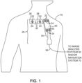
- wires 32, 34, 36 are used to connect localization elements 24 in each of first, second, and third pads 26, 28, 30 to image analysis system 50 (see FIG. 2 ) and/or navigation system 70 (see FIG. 3 ).
- localization elements 24 may be wirelessly connected to navigation system 70.
- FIG. 1 illustrates PTD 20 having six markers 22 and six localization elements 24, but any number of two or more markers 22 and localization elements 24 can be used.
- Patient tracking device (PTD) 20 can be coupled to a dynamic body such as, for example, a selected dynamic portion of the anatomy of a patient 10.
- PTD 20 can be coupled to patient 10 with adhesive, straps, hook and pile, snaps, or any other suitable coupling method.
- the PTD can be a catheter type device with a pigtail or anchoring mechanism that allows it to be attached to an internal organ or along a vessel.
- the anatomy may include, but is not limited to, the lungs, heart, liver, kidneys, and/or other organs of patient 10.
- the population of images can be compiled into an image dataset.
- some or all markers 22 of PTD 20 are visible on the population of images and provide an indication of a position of some or all of markers 22 during the first time interval.
- the position of markers 22 at given instants in time through a path of motion of patient 10 can be illustrated with the images.
- processor 52 receives the population of images from imaging device 40.
- Processor 52 identifies the position of selected markers 22 within the image data or voxel space using various segmentation techniques, such as Hounsfield unit thresholding, convolution, connected component, or other combinatory image processing and segmentation techniques.
- Processor 52 determines a distance and direction between the position of any two markers 22 during multiple instants in time during the first time interval, and stores the image data, as well as the position and distance data, within memory component 54. Multiple images can be produced providing a visual image at multiple instants in time through the path of motion of the dynamic body.
- the distance, range, acceleration, and speed between one or more selected pairs of localization elements 24 (and corresponding markers 22) is then determined and various algorithms are used to analyze and compare the distance between selected elements 24 at given instants in time, to the distances between and orientation among corresponding markers 22 observed in a population of pre-procedural images.
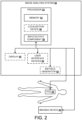
- navigation system 70 comprises a processor 72 having memory component 74, input/output (I/O) component 78, and localization device 76.
- Navigation system 70 also includes display 80, electromagnetic field generator 82, and/or user interface device(s) 84 (e.g., keyboard, mouse).
- navigation system 50 further includes and/or is in data communication with imaging device 40 (see FIG. 2 ).
- the distance, range, acceleration, and speed between one or more selected pairs of localization elements 24 (and corresponding markers 22) is then determined and various algorithms are used to analyze and compare the distance between selected elements 24 at given instants in time, to the distances between and orientation among corresponding markers 22 observed in a population of pre-procedural images.
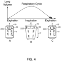
- localization elements 24 of PTD 20 may be tracked continuously during the first and/or second time intervals, a sequence of motion of PTD 20 that represents the motion of an organ of patient 10 or the patient's 10 respiratory cycle may be collected. As patient 10 inhales and exhales, the individual localization elements 24 of PTD 20 will move relative to one another. That is, as patient 10 inhales, the distance between some or all of localization elements 24 of PTD 20 may increase. Conversely, as patient 10 exhales, the distance between some or all of localization elements 24 of PTD 20 may decrease.
- the sequence of motion of localization elements 24 is tracked by image analysis system 50 and/or navigation system 70 and image analysis system 50 and/or navigation system 70 derives a respiratory signal based on the positions of localization elements 24 during the respiratory cycle of patient 10.
- the sequence of motion may then be analyzed to find unique similar points within the image dataset and images within the image dataset may be grouped.
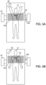
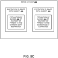
- FIGS. 5A and 5B illustrate the generation of a population of images during a first time interval using imaging device 40, PTD 20, and optionally electromagnetic field generator 62 of image analysis system 50.
- patient 10 inhales and patient 10 is scanned using imaging device 40 which generates a population of images 402 of the anatomy of patient 10 and markers 22 at inspiration.
- patient 10 may place their arms above their head as they inhale, and this may be considered a total lung capacity (TLC) scan.
- FIG. 5B patient 10 exhales and patient 10 is scanned using imaging device 40 which generates a population of images 404 of the anatomy of patient 10 and markers 22 at expiration.
- acquiring a population of images at both inspiration and expiration may assist navigation of a steerable catheter during a second time interval.
- processor 52 of image analysis workstation 50 in addition to segmenting the markers 22 of PTD 20 from the population of images 402, 404 generated during the first time interval, processor 52 of image analysis workstation 50 generates three-dimensional models of the airway of patient 10 by segmenting the 3D image data subsets 406, 408.
- segmentation of the airway may be accomplished using an iterative region growing technique wherein a seed voxel in the airway is selected as an initialization parameter.
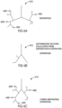
- FIG. 6A shows an Inspiration/arms-up pathway registration; this is, generally speaking, the preferred image scan acquisition state for automatic segmentation of the tracheo-bronchial tree.
- Processor 52 may also segment one or more target tissues 420 (e.g., lesions, lymph nodes, blood vessels, tumors, etc.) which may be navigated to during a second time interval using a variety of medical devices as described more fully elsewhere herein.
- the segmentation of the target tissue(s) 420 may be refined to define different characteristics of the target tissue, such as, for example, density of the target tissue.
- Additional image data formats may also be loaded into processor 52, such as, for example, PET or MR and processor 52 may be able to map the CT, PET, and/or MR data to one another.
- expiration 3D airway model 412 includes fewer structure(s) and the structure(s) are in different locations and/or orientations than at inspiration.
- the breathing cycle of patient 10 may be closer to tidal breathing. That is, patient 10 usually never reaches full inspiration during the procedure and thus if the segmentation of the airways of patient 10 at inspiration is used for navigation purposes, there will be significant error in the registration of the segmented airway to patient 10.
- the inspiration 3D airway model 410 is deformed to the expiration state of patient 10 using the deformation vector field. Accordingly, the voxels in the inspiration 3D airway model 410 are deformed to match the location, shape, and orientation of the airways of patient 10 at expiration.
- this structural information is now more closely matched to the location, shape, and orientation of the airways of patient 10 depicted in expiration 3D airway model 412. Accordingly, the deformation vectors represent not only a change in location of the structure of the airway but a change in shape of the structure of the airway from inspiration to expiration.
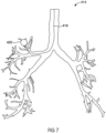
- FIG. 7 illustrates a 3D representation of hybrid "Inspiration-Expiration" 3D airway model 414 which includes a target tissue 420 segmented by processor 52, 72.
- This 3D representation of hybrid "Inspiration-Expiration" 3D airway model 414 may include surface information.
- Hybrid "Inspiration-Expiration" 3D airway model 414 may additionally include navigation pathway 416.
- Image analysis system 50 and/or navigation system 70 may calculate navigation pathway 416 from the entry of the airway to the location of target tissue 420.
- navigation pathway 416 may be an optimal endobronchial path to a target tissue.
- navigation pathway 416 may represent the closest distance and/or closest angle to the target tissue.
- a physician or other healthcare professional may follow navigation pathway 416 during an image guided intervention to reach the location of target tissue 420.
- target tissue 420 locations and navigation pathway(s) 416 may be automatically calculated by image analysis system 50 and/or navigation system 70, a physician or other healthcare professional may manually adjust target tissue 420 locations and/or navigation pathway(s) 416.
- "Inspiration to Expiration" CT fusion using the lung lobe centroid and vector change to modify an airway model may also be applicable.
- this technique is used to translate and scale each airway based on the lung lobe change between inspiration images and expiration images.
- the lung is constructed of multiple lobes and these lobes are commonly analyzed for volume, shape, and translation change. Each lobe changes in a very different way during the patient's breathing cycle. Using this information to scale and translate the airways that are located in each lobe, it is possible to adapt for airway movement.
- This scaled airway model may then be linked to the 4D tracking of the patient as described herein.
- navigation system 70 uses the respiratory signal derived from PTD 20, navigation system 70 selects an image from the population of pre-procedural images 402, 404 taken during the first time interval that indicates a distance or is grouped in a similar sequence of motion between corresponding markers 22 at a given instant in time, that most closely approximates or matches the distance or similar sequence of motion between the selected localization elements 24. The process of comparing the distances is described in more detail below.
- navigation system 70 displays images corresponding to the actual movement of the targeted anatomy during the medical procedure being performed during the second time interval. The images illustrate the orientation and shape of the targeted anatomy during a path of motion of the anatomy, for example, during inhaling and exhaling.
- One method of selecting the appropriate image from the population of pre-procedural images 402, 404 is to execute an algorithm that sums all of the distances a1 through a6 and then search for and match this sum to an image containing a sum of all of the distances d1 through d6 obtained pre-procedurally from the image data that is equal to the sum of the distances a1 through a6.
- the difference between these sums is equal to zero, the relative position and orientation of the anatomy or dynamic body D during the medical procedure will substantially match the position and orientation of the anatomy in the particular image.
- the image associated with distances d1 through d6 that match or closely approximate the distances a1 through a6 may then be selected and displayed. For example, FIG.
- the image is a match to the vector or distance data obtained during the medical procedure.
- the image data include an indication of a position of a first marker and an indication of a position of a second marker, as illustrated at step 104.
- the image data include position data for multiple positions of the markers during a range or path of motion of the dynamic body over a selected time interval. As described above, the image data include position data associated with multiple markers, however, only two are described here for simplicity.
- a distance between the position of the first marker and the position of the second marker is determined for multiple instants in time during the first time interval, at step 106. As also described above, the determination may include determining the distance based on the observable distance between the markers on a given image.
- the image data, including all of the images received during the first time interval, the position, and the distance data is recorded in a memory component at step 108.
- a distance between the first and second localization elements is determined at step 114. Although only two localization elements 24 are described, as with the markers, position data associated with more than two localization elements may be received and the distances between the additional localization elements may be determined.
- the location of these devices are tracked in relation to PTD 20. In other embodiments, for example, these devices are tracked in relation to electromagnetic field generator 62, 82. It is also envisioned that at least some of these medical devices may be wireless or have wireless communications links. It is also envisioned that the medical devices may encompass medical devices which are used for exploratory purposes, testing purposes or other types of medical procedures.
- localization elements 610 comprise other localization devices such as radiopaque markers that are visible via fluoroscopic imaging and echogenic patterns that are visible via ultrasonic imaging.
- localization elements 610 may be, for example, infrared light emitting diodes, and/or optical passive reflective markers. Localization elements 610 may also be, or be integrated with, one or more fiber optic localization (FDL) devices. Accordingly, in certain embodiments, localization elements 610 may be substantially similar or identical to localization elements 24 of PTD 20. In other embodiments the steerable catheter may be non-navigated, such that it does not include any localization elements.
- any number of medical devices or therapies may be inserted into working channel(s) 608 and/or extended out of tip 607 to deliver the medical devices or therapies to a target tissue.
- the medical devices may include, but are not limited to, imaging devices 633, tissue sensing devices 632, biopsy devices, therapy devices, steerable catheters, endoscopes, bronchoscopes, percutaneous devices, percutaneous needles, pointer probes, implants, stents, guide wires, stylets, etc.
- imaging device 633 is a bronchoscopic video camera 630.
- Bronchoscopic video camera 630 may be inserted into working channel 608 and/or extended out distal end portion 606 of navigated steerable catheter 600. By inserting bronchoscopic video camera 630 into working channel 608 of steerable catheter 600, steerable catheter 600 may be used like a typical steerable bronchoscope, as described more fully elsewhere herein.
- tissue sensing device 632 may be an imaging device 633, wherein imaging device 633 is an endobronchial ultrasound (EBUS) device 634; however, as described above, it will be understood that imaging device 633 may include, but is not limited to, bronchoscopic video camera 630, an optical coherence tomography (OCT) device, a probe based Confocal Laser Endomicroscopy (pCLE) device, or any known imaging device insertable into working channel 608 of steerable catheter 600.
- EBUS endobronchial ultrasound
- OCT optical coherence tomography
- pCLE probe based Confocal Laser Endomicroscopy
- Port 667 disposed on handle 652, provides access to working channel(s) 658 in cannula 652 of percutaneous needle 650, such that a medical device may be inserted into working channel(s) 658 through port 667.
- Any number of medical devices or therapies, as described herein, may be inserted into working channel(s) 658 and/or extended out of tip 657 to deliver the medical devices or therapies (e.g ., steerable catheters, needles, stents, ablation probes, biopsy devices, guide wires, forceps devices, brushes, stylets, pointer probes, radioactive seeds, implants, endoscopes, energy delivery devices, therapy delivery devices, delivery of energy activated substances (e.g., porfimer sodium) and energy devices, radiofrequency (RF) energy devices, cryotherapy devices, laser devices, microwave devices, diffuse infrared laser devices, fluids, drugs, combinations thereof, or the like) to a target tissue.
- energy activated substances e.g., porfimer sodium
- RF
- navigation system 770 may be able to determine the location of tip 657 in relation to the position of localization element 660 if the length between tip 657 and localization element 660 is input into navigation system 70.
- percutaneous needle 650 is non-navigated, such that it does not include any localization elements. However, the location of percutaneous needle 650 may still be tracked by navigation system 70 if a medical device containing a localization element is inserted into working channel 658 of percutaneous needle 650.
- navigation system 70 may display on display 80 multiple images which may assist a physician or other healthcare professional in conducting the methods described herein.
- Image dataset 400 generated during the first time interval may be registered to patient 10 using PTD 20.
- localization elements 24 of PTD 20 are proximate markers 22 and because one or more markers 22 of PTD 20 are visible in image dataset 400 and localization elements 24 corresponding to the one or more markers 22 are tracked by navigation system 70, image dataset 400 may be registered to patient 10. This registration may be manually accomplished or may be automatically accomplished by navigation system 70.
- registration may be completed by different known techniques.
- point-to-point registration may be accomplished by identifying points in an image space and then touching the same points in patient space. These points are generally anatomical landmarks that are easily identifiable on the patient.
- lumen registration may be accomplished by generating a point cloud within the airways of patient 10 and matching the shape of the generated point cloud to an inspiration 3D airway model 410, an expiration 3D airway model 412, and/or a hybrid "Inspiration-Expiration" 3D airway model 414.
- the point cloud may be generated at the appropriate respiration cycle to match inspiration 3D airway model 410, an expiration 3D airway model 412, and/or a hybrid "Inspiration-Expiration" 3D airway model 414.
- Generation of a point cloud is more fully described in U.S. Ser. No. 13/773,984, entitled “Systems, Methods and Devices for Forming Respiratory-Gated Point Cloud for Four Dimensional Soft Tissue Navigation,” filed on February 22, 2013 .
- surface registration may involve the generation of a surface in patient 10 space by either selecting multiple points or scanning, and then accepting the best fit to that surface in image space by iteratively calculating with processor 72 until a surface match is identified.
- repeat fixation devices entail repeatedly removing and replacing a device (i.e., dynamic reference frame, etc.) in known relation to patient 10 or image fiducials of patient 10.
- Fifth, two-dimensional (2D) image datasets may be registered to three-dimensional (3D) image datasets wherein, the two dimensional image datasets may include, but are not limited to, fluoroscopic images, ultrasound images, etc. and the three-dimensional (3D) image datasets may include, but are not limited, to computed tomography (CT) images, fused computed tomography - positron emission tomography (CT/PET) images, magnetic resonance imaging (MRI) images.
- CT computed tomography
- CT/PET fused computed tomography - positron emission tomography
- MRI magnetic resonance imaging
- automatic registration may be accomplished by first attaching a dynamic reference frame to patient 10 prior to acquiring image data. It is envisioned that other known registration procedures are also within the scope of the present disclosure, such as that disclosed in U.S. Patent No.
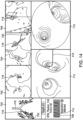
- navigation system 70 displays on display 80 a variety of images as illustrated in FIG. 14 .
- hybrid "Inspiration-Expiration" 3D airway model 414 may be displayed.
- an indicia 718 (shown as a crosshair) of the location of steerable catheter 600 is displayed.
- indicia 718 indicates the location of distal end portion 606 of steerable catheter 600.
- indicia 718 indicates the location of localization element 610 of steerable catheter 600.
- indicia 718 indicates the location of tip 607 of steerable catheter 600.
- Indicia 718, 720 are shown as a crosshair and circle, respectively; however it is envisioned that other indicia may be used to indicate the location of steerable catheter 600, initial target tissue location, confirmed target tissue location, location of percutaneous needle 650, and/or any other target tissue or medical device.
- indicia may have different shapes, colors, sizes, line weights and/or styles, etc. without departing from the scope of the disclosure.
- navigation system 70 may be able to simulate and display axial, coronal and oblique images based on the position and orientation (POSE) of localization element 610 of steerable catheter 600, as shown in panels 702, 704, and 706. To simulate these views, navigation system 70 may modify one or more images from image dataset 400 using known image manipulation techniques. Additionally, navigation system 70 may simulate and/or display orthogonal image slices, oblique or off-axis image slices, volume rendered images, segmented images, fused modality images, maximum intensity projection (MIPS) images, video, and video enhanced images. As shown, indicia of 718 of steerable catheter 600 and/or an indicia 720 of an initial target tissue location may also be displayed, as shown in panels 702, 704, and 706.
- PES position and orientation
- the point of view may be adjusted to match bronchoscopic video camera 630 or to display a virtual volumetric scene from different points along the airway or outside the airway.
- Navigation system 70 may also be able to display a navigation pathway 416 in the virtual volumetric scene. Accordingly, the virtual volumetric scene may allow a physician or other healthcare professional to review the navigation pathway 416 prior to inserting steerable catheter 600 and/or other medical device into patient 10. Additionally, in certain embodiments, an indicia of the location of localization element 610 of steerable catheter 600 and/or an indicia of an initial target tissue location may also be displayed.
- navigation system 70 also displays a real-time image feed from bronchoscopic video camera 630 inserted into working channel 608 of steerable catheter 600.
- the real-time image feed may be static images or moving video.
- the real-time image feed may assist the physician or other healthcare professional in navigating steerable catheter 600 to proximate the initial location of the target tissue.
- steerable catheter 600 may be used like a typical steerable bronchoscope.
- Typical steerable bronchoscopes are used to visually inspect the airways of a patient and have a fixed bronchoscopic video camera in addition to one or more working channels.
- Typical steerable bronchoscopes may have steering actuators and steering mechanisms that permit them to be steered much like steerable catheter 600. Because the bronchoscopic video camera of a typical steerable bronchoscope is fixed during manufacture of the steerable bronchoscope, the "up" orientation of the image feed from the bronchoscopic video camera as displayed to the physician or other healthcare professional is aligned with the "up" direction of the steering actuator of the typical steerable bronchoscope. That is, the orientation of the real-time image feed from the typical steerable bronchoscope is registered to the orientation of the steering directions of the typical steerable bronchoscope.
- the ratio(s) of the diameter(s) of working channel(s) 608 of steerable catheter 600 to the outside diameter of steerable catheter 600 may be much higher than the ratio(s) of the diameter(s) of working channel(s) of a typical steerable bronchoscope to the outside diameter of a typical steerable bronchoscope.
- the "up" orientation of the real-time image feed from bronchoscopic video camera 630 as displayed to the physician or other healthcare professional should be aligned with the "up" direction of steering actuator 614 of steerable catheter 600.
- bronchoscopic video camera 630 is inserted into working channel 608 of steerable catheter 600.
- tip 631 (see FIG. 12A ) of bronchoscopic video camera 630 is positioned proximate or extended past tip 607 of steerable catheter 600.
- a real-time image feed of one or more reference points is generated using bronchoscopic video camera 630, wherein the orientation of the reference point(s) is known. That is, the physician or other healthcare professional may know or ascertain the orientation of the reference point(s) independently from the real-time image feed.
- handle 612 of steerable catheter 600 is considered to be in a neutral position when longitudinal axis 613 of handle 612 is substantially vertical, when no "up” or “down” steering input is applied to steerable catheter 600 by steering actuator 614, and when no "left” or “right” steering input is applied to steerable catheter 600 by rotation of handle 612 about longitudinal axis 613.
- handle 612 of steerable catheter 600 is considered to be in a neutral position when longitudinal axis 613 of handle 612 is substantially vertical, when no "up” or “down” steering input is applied to steerable catheter 600 by steering actuator 614, and when no "left” or “right” steering input is applied to steerable catheter 600 by rotation of handle 612 about longitudinal axis 613.
- elongate flexible shaft 602 of steerable catheter 600 may be flexed; however it is contemplated that no additional steering inputs are applied to steerable catheter 600.
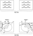
- a jig 802 may be used in conjunction with the method of registering the real-time image feed from a bronchoscopic video camera 630 to a steerable catheter 600 described in FIG. 15 .
- jig 802 may include receiver 803 into which distal end portion 606 of steerable catheter 600 may be placed.
- Jig 802 further includes three round objects 804 which serve as the reference points described above. Accordingly, when viewed along arrow A, round objects 804 are known to be oriented as shown in FIG. 16A .
- jig 802 may include one or more reference points. In other embodiments, for example, jig 802 may include a picture or pattern which serves as the one or more reference points.
- the registration may be confirmed by steering steerable catheter 600 to cause a deflection of distal end portion 606 of elongate flexible shaft 602 in a direction and observing that the displayed real-time image feed moves in that same direction.
- the displayed real-time image feed will also move “up.”
- the physician or other healthcare professional manipulates steering actuator 614 to cause a "down” deflection in distal end portion 606 of elongate flexible shaft 602
- the displayed real-time image feed will also move “down.”
- the physician or other healthcare professional rotates handle 612 "left” or “right” to cause a "left” or “right” deflection in distal end portion 606 of elongate flexible shaft 602
- the displayed real-time image feed will also move “left” or “right.” Accordingly, after the real-time image feed is registered to steerable catheter 600,
- the virtual volumetric scene displayed in panel 712 may be registered to the real-time image feed from a bronchoscopic video camera 630 displayed in panel 716.
- steerable catheter 600 may be positioned in such a way such that what appears "up” in the real-time image feed may not correspond to the physical "up” direction of patient 10. That is, the physical "up” of patient 10 usually corresponds to the anterior direction of patient 10 as patient 10 is oriented during the procedure.
- patient 10 is in the supine position and thus, the physical "up” of the patient will correspond to an actual “up.”
- patient 10 may be in different orientations during the procedure, such as on their side or chest
- the virtual volumetric scene displayed in panel 712 is shown with the chest of patient 10 facing up.
- the real-time image feed as shown in panel 716 may not match the virtual volumetric scene displayed in panel 712.
- the virtual volumetric scene may be registered to the real-time image feed, wherein the real-time image feed has been registered to steerable catheter 600.
- the virtual volumetric scene may be registered to the real-time image feed using intensity based maximization of information mutual to the real-time image feed and the virtual volumetric scene instead of matching structures.
- surface normals of the real-time image feed may be calculated using a linear shape from shading algorithm based on the unique camera and/or lighting configurations of bronchoscopic video camera 630.
- the virtual volumetric scene may then be registered to the real-time image feed by matching the calculated surface normal with surface normal of the virtual volumetric scene. Accordingly, the registration of the virtual volumetric scene to the real-time image feed may cause both the real-time image feed and the virtual volumetric scene to be displayed on display 80 with "up" as "up.”
- the registration of the virtual volumetric scene to the real-time image feed may be enhanced by registering the real-time image feed to localization element 610 of steerable catheter 600.
- both the real-time image feed and/or the virtual volumetric scene may be shown in the "up" orientation on display 80 no matter what the position and orientation (POSE) of localization element 610 in steerable catheter 600 is as tracked by navigation system 70.
- PSE position and orientation
- the physician or other healthcare professional may always expect that an "up” steering input on steering actuator 614 will always result in the displayed real-time image moving "up.”
- navigation system 70 may display real-time image feed and/or virtual volumetric scene with "up” as “up.” Accordingly, the physician or other healthcare professional may still be able to easily determine how to manipulate steering actuator 614 of steerable catheter 600 to navigate steerable catheter 600 along navigation pathway 416 displayed in panel 712.
- a method of registering the real-time image feed from bronchoscopic video camera 630 to localization element 610 of steerable catheter 600 is described.
- registration of the real-time image feed from bronchoscopic video camera 630 to localization element 610 of steerable catheter 600 is performed after the real-time image feed from bronchoscopic video camera 630 is registered to steerable catheter 600.
- navigation system 70 tracks the location of localization element 610 of steerable catheter 600.
- the orientation of the registered real-time image feed with respect to localization element 610 is determined. Referring now to FIG.
- the registration of the virtual volumetric scene may be maintained to the real-time image feed as steerable catheter 600 is navigated in the airway of patient 10.
- navigation system 70 may also display a graphical representation 708 of the respiratory cycle of patient 10 monitored using PTD 20.
- one or more of the images and/or indicia displayed in panels 700, 702, 704, 706, 712 and 716 are displayed as a function of the monitored respiratory state. That is, images in image dataset 400 and/or generated from image dataset 400 are displayed on display 80 that depict the anatomy of patient 10 at the monitored respiratory state. For example, when the patient is at expiration as monitored by PTD 20, images of the anatomy of the patient depicting the anatomy at expiration are displayed. Accordingly, when the patient is at inspiration as monitored by PTD 20, images of the anatomy of patient 10 depicting the anatomy at inspiration are displayed.
- the indicia indicate the location of steerable catheter 600 and percutaneous needle 650 based on the location of localization elements 610, 660 tracked by navigation system 70 as steerable catheter 600 and percutaneous needle 650 are navigated by the physician or other healthcare profession on and/or within patient 10.
- the display of the indicia may be periodically updated based on the timing signal from PTD 20.
- PTD 20 may be connected to navigation system 70.
- Navigation system 70 may then track localization elements 610, 660 in response to a timing signal received from PTD 20. The position of the indicia may then be updated on display 80.
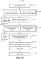
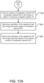
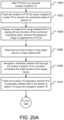
- a method of endobronchially confirming the location of a target in the lung of a patient and percutaneously intercepting the target at the confirmed location may be performed. In various embodiments, this method is performed during a second time interval after an image dataset 400 is generated during a first time interval. As illustrated in FIGS. 20A - 20B , an embodiment of a method of endobronchially confirming the location of a target is illustrated.
- PTD 20 is affixed to the external surface of a patient 10.
- the respiratory state of patient 10 may be monitored by tracking the location of PTD 20 using navigation system 70.
- navigation system 70 displays an image from image dataset 400 on display 80 as a function of the monitored respiratory state.
- the displayed image is selected from one or more images in image dataset 400 and/or is generated by navigation system 70 using one or more images in image dataset 400.
- the displayed image is registered to PTD 20.
- an initial location of one or more target tissues in image dataset 400 is determined. This initial location of the target tissue is where it is believed that a target tissue is located within patient 10.
- the physician or other healthcare professional may then determine the initial location of the target tissue(s) by selecting the target tissue depicted on display(s) 50, 80 using user interface device(s) 64, 84 (e.g., by clicking on displayed target tissue with a mouse) or some other point selection tool.
- the initial location of the target tissue may be determined by the physician or other healthcare professional using nodule segmentation tools and/or using nodule density information.
- An indicia 720 of the initial target tissue location may then be displayed on display 80 as shown in FIG. 14 .
- a physician or other healthcare professional navigates steerable catheter 600 through the airway of patient 10 to a position proximate the initial location of the target tissue.
- an imaging device 633 such as bronchoscopic video camera 630 (see FIG. 12A ) is inserted into working channel 608, navigation system 70 displays on display 80 the real-time image feed of the inside of the airway of patient 10 generated by bronchoscopic video camera 630 as shown in panel 716 of FIG. 14 .
- the real-time image feed may be registered to steerable catheter 600.
- navigation system 70 may overlay navigation pathway 416 onto the real-time image feed from bronchoscopic video camera 630.
- navigation system 70 tracks the location of localization element 610 of steerable catheter 60.
- an indicia of 718 of the location of steerable catheter 600 may also be displayed on display 80 as shown in panels 700, 702, 704, and 706 of FIG. 14 .
- Navigation system 70 may be able to display an indicia 720 (shown as circle in crosshair bounded by a circle) of the initial location of the target tissue, an indicia 722 of the confirmed location of the target tissue, and an indicia 718 (shown as crosshair) of steerable catheter 600.
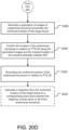
- the method may optionally continue according to steps illustrated in FIGS. 20C and 20E as described more fully elsewhere herein.
- the physician or other healthcare professional can return to the confirmed location of the target tissue using a medical device, such as steerable catheter 600 or percutaneous needle 650, without needing to re-register the patient. Accordingly, because, in certain embodiments, the confirmed location of the target tissue is recorded in relation to the location of patient tracking device 20, the physician or other healthcare professional can navigate medical device to the confirmed location of the target tissue knowing the location of patient tracking device 20.
- the target tissue may be sampled using a variety of medical devices including, but not limited to, forceps devices, needles, brushes, etc. Treatment may also be endobronchially delivered to the confirmed location of the target tissue using a variety of medical devices including, but not limited to, ablation probes, radioactive seeds, implants, energy delivery devices, therapy delivery devices, delivery of energy activated substances (e.g., porfimer sodium) and energy devices, radiofrequency (RF) energy devices, cryotherapy devices, laser devices, microwave devices, diffuse infrared laser devices, fluids, drugs, combinations thereof, or the like.
- ablation probes including, but not limited to, ablation probes, radioactive seeds, implants, energy delivery devices, therapy delivery devices, delivery of energy activated substances (e.g., porfimer sodium) and energy devices, radiofrequency (RF) energy devices, cryotherapy devices, laser devices, microwave devices, diffuse infrared laser devices, fluids, drugs, combinations thereof, or the like.
- RF radiofrequency
- percutaneous device may include, but is not limited to percutaneous needle 650, a thoracic wedge resection device, a biopsy gun, a tracked core biopsy device, and/or any other medical device which may be used to percutaneously intercept a target tissue.
- the percutaneous devices preferably include a localization element so that the position and orientation (POSE) of the percutaneous devices may be tracked by navigation system 70.
- an alternative suggested trajectory may be calculated and displayed which permits entry through the chest or side of patient 10.
- a displayed trajectory may be an actual trajectory calculated by navigation system 70 wherein the actual trajectory is the based on where percutaneous needle 650 is located and oriented by physician or other healthcare professional.
- navigation system 70 may be able to display on display 80 both a suggested trajectory and an actual trajectory of percutaneous needle 650.
- a physician or other healthcare professional may move tip 657 of percutaneous needle 650 along the body of patient 10 and may orient percutaneous needle 650 so that the suggested trajectory and the actual trajectory displayed by navigation system 70 on display 80 are in alignment.
- the physician or other healthcare professional inserts percutaneous needle 650 into patient along the actual trajectory.
- no suggested trajectory may be displayed.
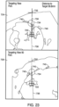
- FIG. 23 illustrates one embodiment where navigation system 70 displays on display 80 suggested and actual trajectories from an entry point on the surface of patient 10 to the confirmed location of the target tissue.
- Panels 724 and 726 illustrate views that navigation system 70 may display.
- the displayed images may be selected from one or more images in image dataset 400 or may be generated by navigation system 70 using one or more images in image dataset 400.
- indicia 722 shown as crosshair bounded by a square
- indicia 734 of the location of percutaneous needle 650 is displayed.
- the physician or other healthcare professional inserts percutaneous needle 650 into the patient and navigates tip 657 proximate to the confirmed location of the target tissue. Then at step 1024, the target tissue at the confirmed location is intercepted.
- intercepting the target tissue at the confirmed location includes inserting a biopsy device into working channel 658 of percutaneous needle 650 and extending the biopsy device beyond tip 657 to sample the target tissue.
- intercepting the target tissue at the confirmed location includes inserting a therapy device into working channel 658 of percutaneous needle 650 and delivering therapy to the target tissue.
- therapy device may be an ablation probe and navigation system 70 may be able to display on display 80 ablation models at the confirmed location of the target tissue.
- the ablation models may assist the physician or other healthcare professional in delivering the appropriate amount of treatment to the target tissue.
- the method may optionally continue according to steps illustrated in FIG. 20D as described more fully elsewhere herein.
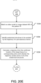
- the method as described in FIGS. 20A - 20C may further include the step of taking a population of images of at least a portion of percutaneous needle 650 at the confirmed location of the target tissue using imaging device 633 disposed in the airway of the patient.
- imaging device 633 may be EBUS device 634 extended out tip 607 of steerable catheter 600.
- the images may be used to confirm that tip 657 of percutaneous needle 650 was actually navigated to proximate the confirmed location of the target tissue.
- the image(s) of percutaneous needle 650 at the confirmed location of the target tissue may be recorded into a patient file as proof that the confirmed location of the target was reached.
- a sensing device may be used to sense the presence of at least a portion of percutaneous needle 650 at the confirmed location of the target tissue.
- the sensing device may include, but is not limited to, a heat sensor, magnetic sensor, electrical sensor, that may be extended out tip 607 of steerable catheter 600.
- the sensing device may also be able to sense the presence of the biopsy device sampling the target tissue and/or the therapy device delivering therapy to the target tissue.
- a heat sensor extended out tip 607 of steerable catheter 600 may be used to determine when the target tissue has been sufficiently treated.
- navigating steerable catheter 600 down multiple airways adjacent to a target tissue and extending a heat sensor out tip 607 of steerable catheter 600 in each of the adjacent airways may be used to determine when a target tissue that is located between the adjacent airways has been treated.
- heat sensors may be placed in multiple airways adjacent to a target tissue using steerable catheter 600 and the multiple heat sensors may be used to determine when a target tissue that is located between the adjacent airways has been treated.
- the imaging device may be EBUS device 634 extended out tip 607 of steerable catheter 600.
- a confirmed location of the anatomical structure(s) is determined in relation to the location of PTD 20 using the population of images and the tracked location of localization element 610 of steerable catheter 600.
- navigation system 70 tracks the extension (x), if any, of EBUS device 634 in relation to localization element 610. By tracking the extension (x) in relation to localization element 610, navigation system 70 knows the coordinates at which the population of images of the anatomical structure(s) are generated and may thus determine the actual location and size of the anatomical structure(s) within patient 10 with respect to PTD 20.
- recording the confirmed location of the anatomical structure(s) comprises recording four-dimensional (4D) data comprising a three-dimensional location (3D) of the confirmed anatomical structure(s) in relation to PTD 20 and a cardiac state of the patient at the time the location of the anatomical structure(s) was confirmed.
- recording the confirmed location of the anatomical structure(s) comprises recording four-dimensional (4D) data comprising a three-dimensional location (3D) of the confirmed anatomical structure(s) in relation to electromagnetic (EM) field generator 82 and a cardiac state of the patient at the time the location of the anatomical structure(s) was confirmed.
- EM electromagnetic
- a dye may be injected into the target tissue at the confirmed location using a needle inserted into working channel 608 of steerable catheter 600 or using a needle inserted into working channel 658 of percutaneous needle 650 (for example, using a marking assembly as described in detail below).
- a marking assembly as described in detail below.
- a sample of air proximate the confirmed location of the target tissue may be taken. Then cells, scents or other potential indicators of cancer within the air sample may then be analyzed to determine if the target tissue is cancerous.
- a breath analysis device may be inserted into working channel 608 of steerable catheter 600 and this breath analysis device may sample the air in situ.
- a vacuum of air may be drawn on working channel 608 from port 616 to sample the air proximate the confirmed location of the target tissue may be taken.
- the method comprises affixing the patient tracking device to an external surface of the patient, tracking the location of the patient tracking device using the navigation system, displaying an image from the image dataset on the display, wherein the displayed image is registered to the patient tracking device, and determining an initial location of the target tissue in the image dataset and navigating a steerable catheter through the airway of the patient to a position proximate the initial location.
- the steerable catheter has a proximal end portion and a distal end portion terminating in a tip, a working channel extending there between, and a localization element disposed proximate the distal end portion thereof.
- the method further comprises tracking the location of the localization element of the steerable catheter in the airway using the navigation system, generating information regarding the presence of the target tissue using a tissue sensing device inserted into the working channel of the steerable catheter, and determining a confirmed location of the target tissue using the generated information regarding the presence of the target tissue and the tracked location of the localization element.
- the method further comprises recording the confirmed location of the target tissue and, displaying the confirmed location of the target tissue on the display of the navigation system in an image from the image dataset.
- the method further comprises determining an initial location of the target tissue in the image dataset and navigating a steerable catheter through the airway of the patient to a position proximate the initial location.
- the steerable catheter has a proximal end portion and a distal end portion terminating in a tip, a working channel extending there between, and a localization element disposed proximate the distal end portion thereof.
- the method further comprises tracking the location of the localization element of the steerable catheter in the airway using the navigation system, generating one or more images of the target tissue using an imaging device inserted into the working channel of the steerable catheter, and determining a confirmed location of the target tissue in relation to the patient tracking device using the generated images and the tracked location of the localization element.
- the method further comprises recording the confirmed location of the target tissue, the recording comprising four-dimensional data comprising a three-dimensional location of the confirmed target tissue in relation to the patient tracking device and the respiratory state of the patient at the time the location of the target tissue was confirmed and applying the confirmed location of the target tissue to an image from the image dataset depicting the airway at the respiratory state of the patient at the time the location of the target tissue was confirmed.
- the method further comprises displaying the confirmed location of the target tissue on the display of the navigation system in an image from the image dataset, the displayed image depicting the airway at the respiratory state of the patient at the time the location of the target tissue was confirmed.
- the method comprises displaying a trajectory of a percutaneous device from an entry point on the patient's body to the confirmed location on the display of the navigation system, wherein the percutaneous device includes a localization element, inserting the percutaneous device into the patient and navigating the percutaneous device to the confirmed location, and intercepting the target tissue at the confirmed location.
- Yet another aspect of the present invention is directed to the construction and use of a hybrid "Inspiration-Expiration" 3D airway model.
- the hybrid “Inspiration-Expiration" 3D airway model may be used to reduce or eliminate errors in registration.
- Constructing the hybrid "Inspiration-Expiration" 3D airway model comprises calculating a population of deformation vector fields, wherein the deformation vector field(s) comprise vectors from one or more voxels in inspiration images or in an inspiration 3D airway model to one or more corresponding voxels in expiration images or in an expiration 3D airway model. After the deformation vector field is calculated, the inspiration images and/or the inspiration 3D airway model may be deformed to the expiration state of the patient using the deformation vector field.
- the voxels in the inspiration images and/or inspiration 3D airway model are deformed to match the location, shape, and orientation of the airways of the patient at expiration.
- this structural information is now more closely matched to the location, shape, and orientation of the airways of the patient depicted in the expiration images and/or expiration 3D airway model.
- the deformation vectors represent a change in location of the structure of the airway and a change in shape of the structure of the airway from inspiration to expiration.
- Yet another aspect of the present invention is directed to a method of injecting dye into a target tissue using a needle inserted into the working channel of a steerable catheter or using a needle inserted into the working channel of a percutaneous needle.
- the physician or other healthcare professional may be able to visually see the dye. This may assist the physician or healthcare professional in sampling and/or treating the correct target tissue.
- Yet another aspect of the present invention is directed to a method of simulating and/or displaying a variety of image views using a navigation system based on the position and orientation (POSE) of a localization element in a steerable catheter, percutaneous device, and/or some other medical device.
- the navigation system may be able to simulate and/or display axial images, coronal images, oblique images, orthogonal image slices, oblique or off-axis image slices, volume rendered images, segmented images, fused modality images, maximum intensity projection (MIPS) images, video, and video enhanced images.
- the navigation system may modify one or more images from an image dataset using known image manipulation techniques.
- the images in the image dataset may be fluoroscopic images, ultrasound images, to computed tomography (CT) images, fused computed tomography - positron emission tomography (CT/PET) images, magnetic resonance imaging (MRI) images, etc.
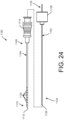
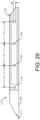
- the wall 1106 of the cannula 1104 includes holes or openings 1120 at a distal portion of the cannula.
- the openings 1120 allow fluid communication between the hollow interior or lumen of the cannula 1104 and an outside of the cannula.
- the openings 1120 are positioned as spaced locations around the wall 1106.
- the openings 1120 are uniformly spaced along the distal portion of the cannula 1104.
- the openings 1120 can be uniformly spaced longitudinally and/or radially.
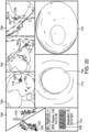
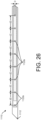
- the distal portion includes diametrically opposed pairs of openings 1120. As seen in FIG.
- the cannula 1104 includes 7 pairs of diametrically opposed openings extending vertically through the cannula at longitudinally spaced locations (vertical openings 1120a, spaced a distance d1 center-to-center). As seen in FIG. 26 , the cannula 1104 includes 8 pairs of diametrically opposed openings extending horizontally through the cannula at longitudinally spaced locations (horizontal openings 1120b, spaced a distance d2 center-to-center). In the embodiment illustrated in FIGS. 24-27 , the vertical openings 1120a and the horizontal openings 1120b are longitudinally spaced from each other such that the horizontal and vertical openings are offset and alternate along the length of the needle 1104.
- the cannula wall 1106 need not include diametrically opposed pairs (i.e., there is only one opening at each longitudinal position along the length of the cannula 1104).
- the cannula 1104 can include any suitable number of openings 1120 (e.g., 16, 30, or any suitable number).
- the openings can extend along any length of the distal portion of the cannula 1104, as measured from the distal end 1110.
- the openings 1120 extend along the cannula 1104 for a distance of approximately 2 cm from the distal end.
- the openings 1120 extend along the cannula 1104 for a distance of approximately 1 cm.
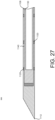
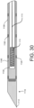
- the stylet 1102 is hollow, having a wall 1130 extending from a proximal end 1132 to a distal end 1134 of the stylet. As illustrated in FIGS. 27 and 30 , the distal end 1134 of the stylet 1102 is closed. The closed distal end 1134 of the stylet 1102 includes a blunt tip 1136.
- the stylet 1102 includes a hub 1138 at the proximal end 1132 thereof. In one embodiment the hub 1138 of the stylet 1102 is configured to engage the hub 1114 of the cannula 1104 to restrict movement of the stylet and the cannula relative to each other.
- the stylet 1102 When the stylet 1102 is positioned, received, or mounted within the cannula 1104, there is a circumferential space 1140 between the wall 1130 of the stylet and the wall 1106 of the cannula.
- the circumferential space 1140 need not be large, merely sufficient to allow the passage of fluid between the stylet 1102 and the cannula 1104.
- the stylet 1102 can be any suitable size so as to fit within the cannula 1104, such as in the range from 15 to 24 gauge.
- the stylet 1102 can be ultra-thin wall, thin wall, or any other suitable type.
- the stylet 1102 is a 22 gauge ultra-thin wall stylet.
- the cannula 1104 is 19 gauge and the stylet is 22 gauge. Other sizes and lengths are within the scope of the present invention.
- the stylet 1102 is configured to be removably received in the cannula 1104. In another embodiment, the stylet 1102 can be affixed inside the cannula 1104.
- the marking assembly 1100 can further include a port in fluid communication with the assembly (e.g., side or "T" port 1142 in FIG. 31 ).
- the port 1142 is configured for connection to a standard syringe for injection of fluid into the cannula 1104. Fluid (e.g., dye) injected into the port 1142 will flow into the circumferential space 1140 between the stylet 1102 and the cannula 1104 and exit the cannula through the holes 1120 in the cannula wall 1106. Fluid exiting the cannula 1104 through the openings 1120 will travel along the outer surface of the cannula 1104.
- Fluid e.g., dye
- the stylet 1102 is removably attached to the cannula 1104, and the stylet is removed before injecting fluid (e.g., dye) through the port in the needle hub. If the stylet remains in the cannula when the fluid is injected, tracking can continue during injection of the fluid.
- fluid e.g., dye
- the stylet 1102 is positioned in the cannula 1104.
- the stylet is affixed in the cannula (e.g., by gluing or other suitable attachment).
- the cannula and stylet assembly is inserted into a patient and navigated using an electromagnetic navigation system to a target in the patient (e.g., a nodule in the lungs or other soft tissue).
- a syringe containing a dye is attached to a side port in fluid communication with the assembly to inject the dye (or other fluid) into the cannula.
- the dye flows between the stylet and the cannula and exits the cannula through the holes in the side wall of the cannula to mark the target with the dye.
- the stylet 1102 is removably attached to the cannula 1104, the stylet is removed and dye is injected into the hub of the cannula (such that dye flows through the lumen of the needle and then out the holes in the side wall of the cannula).
- the marking assembly is structured and configured such that the dye will flow out of the holes in the cannula and up along the outer surface of the cannula to mark the target tissue all the way up to a surface of the tissue, thereby identifying the target tissue to a practitioner.
- the stylet includes a localization element for real-time navigation, as described in other methods disclosed herein.
- the marking assembly can also be used to deliver other material to the target tissue.
- the assembly can be used to deliver a therapy-based liquid or gas agent to the target tissue, such as steam, radiation, brachytherapy seeds, brachytherapy microspheres, radioembolization, drugs, etc.
- a therapy-based liquid or gas agent such as steam, radiation, brachytherapy seeds, brachytherapy microspheres, radioembolization, drugs, etc.
- Other materials for delivery to the target tissue and uses of the marking assembly are within the scope of the present disclosure.
- the marking assembly includes an integrated injection device configured to measure the amount of fluid (e.g., dye) to inject.
- the openings in the wall 1106 of the cannula 1104 are slits, instead of the round holes illustrated.
- the marking assembly includes an outer cannula, in which the cannula 1104 and the stylet 1102 are received.
- the outer cannula includes an open distal end.
- the cannula 1104 includes an open distal end, and the stylet 1102 has a pointed tip that can extend distally beyond the cannula to pierce tissue.
- Other configurations are within the scope of the present disclosure.
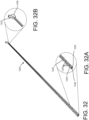
- a marking assembly 1200 includes a coaxial lumen having an inner pipette or cannula 1202 for passing a stylet and an outer pipette or cannula 1204 for conveying fluid (e.g., contrast dye).
- the coaxial lumen as illustrated has an open end, in contrast to the marking assembly embodiments described above, although other configurations are within the scope of the present disclosure.
- a circumferential space 1240 is defined between the inner and outer cannulas 1202, 1204 of the coaxial lumen.
- the coaxial lumen includes a hub having a first port 1242 in fluid communication with the circumferential space 1240 between the inner and outer cannulas 1212, 1204, and a second port 1238 providing passage through the inner cannula 1202 for insertion and advancement of a stylet therethrough to biopsy and/or treat tissue.
- the outer pipette or catheter 1204 is configured for percutaneous use (e.g., has a pointed or tapered tip 1248).
- the inner pipette or catheter 1202 comprises a hollow cylindrical tube having an outlet hub recessed within the hub of the outer pipette.
- the wall of the outer pipette includes holes or openings 1220 providing fluid communication between the lumen of the outer pipette or circumferential space 1240 and the exterior of the marking assembly 1200. In one embodiment, the openings 1220 are uniformly spaced, although other configurations are within the scope of the present disclosure.
- fluid e.g., dye
- fluid e.g., dye
- the marking assembly 1200 When fluid (e.g., dye) is injected into the marking assembly 1200 through the port 1242 (e.g., at arrow B), it flows through the circumferential space 1240 between the pipettes and out the openings 1220 to mark the target tissue.
- the fluid can be inserted into the marking assembly whether or not a stylet is passed through the inner pipette 1202, as the circumferential space 1240 is maintained with or without the stylet.
- a stylet (not shown) can be inserted into the port 1238 (e.g., at arrow A and through the lumen 1244 of the inner cannula 1202) for biopsy or treatment of the tissue.
Landscapes
- Health & Medical Sciences (AREA)
- Life Sciences & Earth Sciences (AREA)
- Engineering & Computer Science (AREA)
- Surgery (AREA)
- General Health & Medical Sciences (AREA)
- Veterinary Medicine (AREA)
- Public Health (AREA)
- Biomedical Technology (AREA)
- Heart & Thoracic Surgery (AREA)
- Medical Informatics (AREA)
- Animal Behavior & Ethology (AREA)
- Molecular Biology (AREA)
- Pathology (AREA)
- Nuclear Medicine, Radiotherapy & Molecular Imaging (AREA)
- Physics & Mathematics (AREA)
- Radiology & Medical Imaging (AREA)
- Biophysics (AREA)
- Robotics (AREA)
- Oral & Maxillofacial Surgery (AREA)
- Optics & Photonics (AREA)
- Vascular Medicine (AREA)
- High Energy & Nuclear Physics (AREA)
- Anesthesiology (AREA)
- Hematology (AREA)
- Magnetic Resonance Imaging Apparatus (AREA)
- Measuring And Recording Apparatus For Diagnosis (AREA)
- Pulmonology (AREA)
- Otolaryngology (AREA)
- Physiology (AREA)
Claims (12)
- Markierungsanordnung, umfassend:eine hohle Kanüle (1104) mit einer Längsachse und einer Wand (1106), die sich von einem proximalen Ende (1108) zu einem geschlossenen distalen Ende (1110) erstreckt, wobei die Wand ein Lumen der Kanüle definiert und die Wand eine Vielzahl von in Längsrichtung entlang einer Länge eines distalen Abschnitts der Kanüle und radial um einen Umfang des distalen Abschnitts der Kanüle beabstandete Öffnungen (1120) definiert, wobei die Vielzahl von Öffnungen ein erstes Paar diametral entgegengesetzter Öffnungen und ein zweites Paar diametral entgegengesetzter Öffnungen, die in Bezug auf die Längsachse zu dem ersten Paar diametral entgegengesetzter Öffnungen senkrecht sind, umfasst, wobei das erste und das zweite Paar diametral entgegengesetzter Öffnungen in Längsrichtung miteinander fluchten;einen Mandrin (1102), der dazu konfiguriert ist, in dem Lumen der Kanüle aufgenommen zu werden, wobei der Mandrin eine Wand (1130) aufweist, die sich von einem proximalen Ende (1132) zu einem distalen Ende (1134) erstreckt, wobei, wenn der Mandrin in dem Lumen der Kanüle aufgenommen ist, ein Umfangsraum zwischen der Wand des Mandrins und der Wand der Kanüle definiert ist, sodass in den Umfangsraum eindringendes Fluid durch die Vielzahl von Öffnungen aus der Kanüle austreten wird.
- Markierungsanordnung nach Anspruch 1, wobei das geschlossene distale Ende der Kanüle eine scharfe Spitze umfasst, die zur perkutanen Verwendung konfiguriert ist.
- Markierungsanordnung nach Anspruch 1, wobei der Mandrin dazu konfiguriert ist, in der Kanüle befestigt zu werden.
- Markierungsanordnung nach Anspruch 1, wobei der Mandrin ein Ortungselement (24) umfasst, das zur Verfolgung durch ein Navigationssystem (70) konfiguriert ist.
- Markierungsanordnung nach Anspruch 4, wobei das Ortungselement einen elektromagnetischen Sensor (1170) umfasst, der in einem hohlen Inneren des Mandrins positioniert ist.
- Markierungsanordnung nach Anspruch 1, wobei der Öffnungen aufweisende distale Abschnitt der Kanüle eine Länge von etwa 2 cm aufweist.
- Markierungsanordnung nach Anspruch 1, wobei der Öffnungen aufweisende distale Abschnitt der Kanüle eine Länge von etwa 1 cm aufweist.
- Markierungsanordnung nach Anspruch 1, wobei:der Mandrin ein offenes proximales Ende und ein geschlossenes distales Ende aufweist; undeinen Port (1142) in Fluidverbindung mit dem Umfangsraum aufweist, wobei in den Port eingespritztes Fluid durch den Umfangsraum fließt und durch die Vielzahl von Öffnungen aus der Kanüle austritt.
- Markierungsanordnung nach Anspruch 8, wobei der Mandrin ein Ortungselement (24) umfasst, das zur Verfolgung durch ein Navigationssystem (70) konfiguriert ist, um eine Echtzeitposition und/oder einen geplanten Pfad des Mandrins zu bestimmen.
- Markierungsanordnung nach Anspruch 9, wobei das Ortungselement einen elektromagnetischen Sensor (1170) an dem distalen Ende des Mandrins umfasst.
- Markierungsanordnung nach Anspruch 1:wobei der Mandrin (1102) dazu konfiguriert ist, in dem Lumen der Kanüle befestigt zu werden; undwobei die Markierungsanordnung ferner einen Port (1142) in Fluidverbindung mit dem Umfangsraum umfasst, wobei in den Port eingespritztes Fluid durch den Umfangsraum fließt und durch die Vielzahl von Öffnungen aus der Kanüle austritt;zur Verwendung in einem Verfahren zum Markieren von Zielgewebe, wobei das Verfahren Folgendes umfasst:Einführen des Mandrins in die Kanüle, sodass das geschlossene distale Endes des Mandrins dem geschlossenen distalen Ende der Kanüle benachbart ist;Navigieren des Mandrins und der Kanüle zu einem Zielgewebe;Einspritzen von Färbemittel in den Port, sodass das Färbemittel durch den Umfangsraum und aus der Vielzahl von Öffnungen heraus in das Zielgewebe fließt, wodurch das Zielgewebe entlang der Außenoberfläche der Kanüle markiert wird.
- Markierungsanordnung nach Anspruch 11, ferner umfassend:
eine Bildanzeige und ein Navigationssystem (70), wobei das Verfahren ferner das Anzeigen eines geplanten Pfads des Mandrins zu dem Zielgewebe auf der Bildanzeige des Navigationssystems umfasst.
Applications Claiming Priority (3)
| Application Number | Priority Date | Filing Date | Title |
|---|---|---|---|
| US201762456308P | 2017-02-08 | 2017-02-08 | |
| US201762561483P | 2017-09-21 | 2017-09-21 | |
| PCT/US2018/017456 WO2018148434A1 (en) | 2017-02-08 | 2018-02-08 | Localization needle |
Publications (3)
| Publication Number | Publication Date |
|---|---|
| EP3579769A1 EP3579769A1 (de) | 2019-12-18 |
| EP3579769A4 EP3579769A4 (de) | 2020-11-18 |
| EP3579769B1 true EP3579769B1 (de) | 2025-04-09 |
Family
ID=63038490
Family Applications (1)
| Application Number | Title | Priority Date | Filing Date |
|---|---|---|---|
| EP18752027.5A Active EP3579769B1 (de) | 2017-02-08 | 2018-02-08 | Lokalisierungsnadel |
Country Status (3)
| Country | Link |
|---|---|
| US (2) | US11439742B2 (de) |
| EP (1) | EP3579769B1 (de) |
| WO (1) | WO2018148434A1 (de) |
Families Citing this family (11)
| Publication number | Priority date | Publication date | Assignee | Title |
|---|---|---|---|---|
| WO2018148434A1 (en) | 2017-02-08 | 2018-08-16 | Veran Medical Technologies, Inc. | Localization needle |
| JP7109936B2 (ja) * | 2018-02-28 | 2022-08-01 | ソニー・オリンパスメディカルソリューションズ株式会社 | 医療用制御装置、および制御方法 |
| WO2020041622A1 (en) * | 2018-08-22 | 2020-02-27 | Bard Access Systems, Inc. | Systems and methods for infrared-enhanced ultrasound visualization |
| JP7410148B2 (ja) * | 2018-12-07 | 2024-01-09 | ヴェラン メディカル テクノロジーズ,インコーポレイテッド | 肺疾患の迅速診断用の経皮カテーテルシステムおよび方法 |
| CN113347936B (zh) * | 2019-01-25 | 2024-07-23 | 伯恩森斯韦伯斯特(以色列)有限责任公司 | 柔性多线圈跟踪传感器 |
| WO2022169525A1 (en) * | 2021-02-04 | 2022-08-11 | Elekta, Inc. | Deformable image registration using deep learning |
| DE102021103411A1 (de) | 2021-02-12 | 2022-08-18 | Aesculap Ag | Chirurgisches Assistenzsystem und Darstellungsverfahren |
| CN116916851A (zh) * | 2021-03-05 | 2023-10-20 | 圣犹达医疗用品心脏病学部门有限公司 | 用于超声导管的柔性电子电路 |
| CN118680675A (zh) * | 2023-03-21 | 2024-09-24 | 直观外科手术操作公司 | 可偏转感测器械系统和方法 |
| WO2025046896A1 (ja) * | 2023-08-31 | 2025-03-06 | オリンパスメディカルシステムズ株式会社 | 内視鏡装置、画像処理装置、院内システム、画像処理方法及び画像処理プログラム |
| WO2025088983A1 (ja) * | 2023-10-24 | 2025-05-01 | 学校法人順天堂 | 画像表示装置、及び画像表示制御プログラム |
Citations (3)
| Publication number | Priority date | Publication date | Assignee | Title |
|---|---|---|---|---|
| US20070213688A1 (en) * | 2003-05-21 | 2007-09-13 | Klein Jeffrey A | Infiltration cannula |
| US20110282337A1 (en) * | 2010-05-12 | 2011-11-17 | Hall Steven G | Instrument for Debriding Fistula and Applying Therapeutic Cells |
| US20160045707A1 (en) * | 2014-08-15 | 2016-02-18 | Ernest A. Conti | Multiple Side Hole Infusion Apparatus |
Family Cites Families (45)
| Publication number | Priority date | Publication date | Assignee | Title |
|---|---|---|---|---|
| FR2622117B1 (fr) * | 1987-10-27 | 1997-01-31 | Cordis Sa | Introducteur de catheter a canule et stylet |
| US5069665A (en) * | 1990-07-02 | 1991-12-03 | Ng Raymond C | Fluid aspiration needle |
| US5470308A (en) | 1992-08-12 | 1995-11-28 | Vidamed, Inc. | Medical probe with biopsy stylet |
| US20050101950A1 (en) | 1995-08-15 | 2005-05-12 | Rita Medical Systems, Inc. | Multiple antenna ablation apparatus and method |
| IL119262A0 (en) * | 1996-02-15 | 1996-12-05 | Biosense Israel Ltd | Locatable biopsy needle |
| US6689142B1 (en) | 1999-04-26 | 2004-02-10 | Scimed Life Systems, Inc. | Apparatus and methods for guiding a needle |
| US8239001B2 (en) * | 2003-10-17 | 2012-08-07 | Medtronic Navigation, Inc. | Method and apparatus for surgical navigation |
| US6613026B1 (en) | 1999-12-08 | 2003-09-02 | Scimed Life Systems, Inc. | Lateral needle-less injection apparatus and method |
| US6770070B1 (en) | 2000-03-17 | 2004-08-03 | Rita Medical Systems, Inc. | Lung treatment apparatus and method |
| US7278972B2 (en) * | 2002-01-24 | 2007-10-09 | Worldwide Medical Technologies, Llc | Combined bone marrow aspiration and core biopsy device |
| US20050277918A1 (en) | 2003-03-07 | 2005-12-15 | Baylis Medical Company Inc. | Electrosurgical cannula |
| US20040176759A1 (en) * | 2003-03-07 | 2004-09-09 | Subashini Krishnamurthy | Radiopaque electrical needle |
| WO2003105668A2 (en) | 2002-06-01 | 2003-12-24 | Alfred E. Mann Institute For Biomedical Engineering At The University Of Southern California | Injection devices and methods for testing implants and for unimpeded target location testing |
| US20070265582A1 (en) | 2002-06-12 | 2007-11-15 | University Of Southern California | Injection Devices for Unimpeded Target Location Testing |
| US20040236313A1 (en) | 2003-05-21 | 2004-11-25 | Klein Jeffrey A. | Infiltration cannula |
| DE102004008366B3 (de) * | 2004-02-20 | 2005-09-15 | Siemens Ag | Vorrichtung zur Durchführung von Laserangioplastie mit OCT-Überwachung |
| US7419497B2 (en) | 2004-04-21 | 2008-09-02 | Acclarent, Inc. | Methods for treating ethmoid disease |
| US20090209804A1 (en) | 2004-07-23 | 2009-08-20 | Calypso Medical Technologies, Inc. | Apparatuses and methods for percutaneously implanting objects in patients |
| US9265523B2 (en) | 2011-10-24 | 2016-02-23 | Nico Corporation | Surgical access system with navigation element and method of using same |
| EP1693011A1 (de) | 2005-02-22 | 2006-08-23 | Depuy International Limited | Instrument zum Einsetzen eines Sensors |
| US8784336B2 (en) | 2005-08-24 | 2014-07-22 | C. R. Bard, Inc. | Stylet apparatuses and methods of manufacture |
| US20070219460A1 (en) | 2006-03-15 | 2007-09-20 | Goldenberg Alec S | Aspiration needles |
| US20080294148A1 (en) * | 2007-05-22 | 2008-11-27 | Albert Gardner | System and method for refilling an implanted delivery device |
| US8690832B2 (en) * | 2007-06-13 | 2014-04-08 | Custom Medical Applications | Retrofitted neural injection system and related methods |
| US8781555B2 (en) | 2007-11-26 | 2014-07-15 | C. R. Bard, Inc. | System for placement of a catheter including a signal-generating stylet |
| US8357175B2 (en) | 2008-12-16 | 2013-01-22 | Nico Corporation | Positioning system for tissue removal device |
| US8632468B2 (en) * | 2009-02-25 | 2014-01-21 | Koninklijke Philips N.V. | Method, system and devices for transjugular intrahepatic portosystemic shunt (TIPS) procedures |
| US20100318031A1 (en) | 2009-06-11 | 2010-12-16 | Kevin Henry | External Stylette Needle and Method of Use |
| EP2605693B1 (de) * | 2010-08-20 | 2019-11-06 | Veran Medical Technologies, Inc. | Vorrichtung für vierdimensionale weichgewebenavigation |
| US9486275B2 (en) * | 2010-12-30 | 2016-11-08 | Avent, Inc. | Electrosurgical apparatus having a sensor |
| US9216070B2 (en) * | 2010-12-31 | 2015-12-22 | St. Jude Medical, Atrial Fibrillation Division, Inc. | Intuitive user guided configuration routine |
| US8747401B2 (en) * | 2011-01-20 | 2014-06-10 | Arthrocare Corporation | Systems and methods for turbinate reduction |
| EP2508217B1 (de) | 2011-04-05 | 2019-09-04 | Kpr U.S., Llc | Anästhesiespritze |
| US8709034B2 (en) | 2011-05-13 | 2014-04-29 | Broncus Medical Inc. | Methods and devices for diagnosing, monitoring, or treating medical conditions through an opening through an airway wall |
| US20130296691A1 (en) | 2012-05-04 | 2013-11-07 | Ascension Technology Corporation | Magnetically tracked surgical needle assembly |
| US9655595B2 (en) * | 2012-06-14 | 2017-05-23 | Arcitrax Inc. | System, method and device for prostate diagnosis and intervention |
| US9364167B2 (en) * | 2013-03-15 | 2016-06-14 | Lx Medical Corporation | Tissue imaging and image guidance in luminal anatomic structures and body cavities |
| JP6557255B2 (ja) | 2014-04-17 | 2019-08-07 | コーニンクレッカ フィリップス エヌ ヴェKoninklijke Philips N.V. | 外科装置の高速移動を検出する方法及びシステム |
| US20150305612A1 (en) * | 2014-04-23 | 2015-10-29 | Mark Hunter | Apparatuses and methods for registering a real-time image feed from an imaging device to a steerable catheter |
| US20150305650A1 (en) * | 2014-04-23 | 2015-10-29 | Mark Hunter | Apparatuses and methods for endobronchial navigation to and confirmation of the location of a target tissue and percutaneous interception of the target tissue |
| US9930652B2 (en) | 2014-12-18 | 2018-03-27 | Intel Corporation | Evolved node-B, user equipment and methods for transition between unlicensed and licensed frequency bands |
| US10357280B2 (en) | 2015-04-30 | 2019-07-23 | Nico Corporation | Navigating introducer for tissue access system |
| US10111715B2 (en) | 2015-05-11 | 2018-10-30 | Veran Medical Technologies, Inc. | Adjustable length medical instrument assembly with localization elements for tracking medical instrument extension |
| US11020174B2 (en) * | 2016-10-17 | 2021-06-01 | Biosense Webster (Israel) Ltd. | Catheter with angled irrigation holes |
| WO2018148434A1 (en) | 2017-02-08 | 2018-08-16 | Veran Medical Technologies, Inc. | Localization needle |
-
2018
- 2018-02-08 WO PCT/US2018/017456 patent/WO2018148434A1/en not_active Ceased
- 2018-02-08 EP EP18752027.5A patent/EP3579769B1/de active Active
- 2018-02-08 US US15/892,218 patent/US11439742B2/en active Active
-
2022
- 2022-08-05 US US17/882,015 patent/US12208232B2/en active Active
Patent Citations (3)
| Publication number | Priority date | Publication date | Assignee | Title |
|---|---|---|---|---|
| US20070213688A1 (en) * | 2003-05-21 | 2007-09-13 | Klein Jeffrey A | Infiltration cannula |
| US20110282337A1 (en) * | 2010-05-12 | 2011-11-17 | Hall Steven G | Instrument for Debriding Fistula and Applying Therapeutic Cells |
| US20160045707A1 (en) * | 2014-08-15 | 2016-02-18 | Ernest A. Conti | Multiple Side Hole Infusion Apparatus |
Also Published As
| Publication number | Publication date |
|---|---|
| EP3579769A4 (de) | 2020-11-18 |
| US11439742B2 (en) | 2022-09-13 |
| EP3579769A1 (de) | 2019-12-18 |
| US12208232B2 (en) | 2025-01-28 |
| US20220379008A1 (en) | 2022-12-01 |
| WO2018148434A1 (en) | 2018-08-16 |
| US20180221566A1 (en) | 2018-08-09 |
Similar Documents
| Publication | Publication Date | Title |
|---|---|---|
| US20230145993A1 (en) | Apparatuses and Methods for Registering a Real-Time Image Feed From an Imaging Device to a Steerable Catheter | |
| US12208232B2 (en) | Localization needle | |
| US10617324B2 (en) | Apparatuses and methods for endobronchial navigation to and confirmation of the location of a target tissue and percutaneous interception of the target tissue | |
| US11830198B2 (en) | Systems, methods and devices for forming respiratory-gated point cloud for four dimensional soft tissue navigation | |
| US11699238B2 (en) | Apparatuses and methods for navigation in and local segmentation extension of anatomical treelike structures | |
| US11547377B2 (en) | System and method for navigating to target and performing procedure on target utilizing fluoroscopic-based local three dimensional volume reconstruction | |
| US11864946B2 (en) | Method of employing a medical apparatus with translatable imaging device for real-time confirmation of interception of target tissue | |
| US8821376B2 (en) | Devices and methods for performing medical procedures in tree-like luminal structures | |
| ES2901703T3 (es) | Integración de múltiples fuentes de datos para localización y navegación | |
| CN110741414A (zh) | 用于使用实时二维荧光镜检查数据识别、标记和导航到靶标的系统和方法 | |
| US20260020922A1 (en) | Systems and methods of moving a medical tool with a target in a visualization or robotic system for higher yields |
Legal Events
| Date | Code | Title | Description |
|---|---|---|---|
| STAA | Information on the status of an ep patent application or granted ep patent |
Free format text: STATUS: THE INTERNATIONAL PUBLICATION HAS BEEN MADE |
|
| PUAI | Public reference made under article 153(3) epc to a published international application that has entered the european phase |
Free format text: ORIGINAL CODE: 0009012 |
|
| STAA | Information on the status of an ep patent application or granted ep patent |
Free format text: STATUS: REQUEST FOR EXAMINATION WAS MADE |
|
| 17P | Request for examination filed |
Effective date: 20190823 |
|
| AK | Designated contracting states |
Kind code of ref document: A1 Designated state(s): AL AT BE BG CH CY CZ DE DK EE ES FI FR GB GR HR HU IE IS IT LI LT LU LV MC MK MT NL NO PL PT RO RS SE SI SK SM TR |
|
| AX | Request for extension of the european patent |
Extension state: BA ME |
|
| DAV | Request for validation of the european patent (deleted) | ||
| DAX | Request for extension of the european patent (deleted) | ||
| A4 | Supplementary search report drawn up and despatched |
Effective date: 20201020 |
|
| RIC1 | Information provided on ipc code assigned before grant |
Ipc: A61B 1/267 20060101ALN20201014BHEP Ipc: A61B 17/34 20060101AFI20201014BHEP Ipc: A61B 34/20 20160101ALI20201014BHEP Ipc: A61B 10/02 20060101ALI20201014BHEP Ipc: A61M 5/158 20060101ALN20201014BHEP Ipc: A61B 8/08 20060101ALI20201014BHEP Ipc: A61B 34/10 20160101ALN20201014BHEP Ipc: A61B 34/00 20160101ALI20201014BHEP Ipc: A61B 90/00 20160101ALI20201014BHEP Ipc: A61B 8/12 20060101ALI20201014BHEP |
|
| STAA | Information on the status of an ep patent application or granted ep patent |
Free format text: STATUS: EXAMINATION IS IN PROGRESS |
|
| 17Q | First examination report despatched |
Effective date: 20230331 |
|
| P01 | Opt-out of the competence of the unified patent court (upc) registered |
Effective date: 20240212 |
|
| GRAP | Despatch of communication of intention to grant a patent |
Free format text: ORIGINAL CODE: EPIDOSNIGR1 |
|
| STAA | Information on the status of an ep patent application or granted ep patent |
Free format text: STATUS: GRANT OF PATENT IS INTENDED |
|
| RIC1 | Information provided on ipc code assigned before grant |
Ipc: A61B 34/10 20160101ALN20241110BHEP Ipc: A61M 5/158 20060101ALN20241110BHEP Ipc: A61B 1/267 20060101ALN20241110BHEP Ipc: A61B 34/20 20160101ALI20241110BHEP Ipc: A61B 34/00 20160101ALI20241110BHEP Ipc: A61B 10/02 20060101ALI20241110BHEP Ipc: A61B 8/12 20060101ALI20241110BHEP Ipc: A61B 8/08 20060101ALI20241110BHEP Ipc: A61B 90/00 20160101ALI20241110BHEP Ipc: A61B 17/34 20060101AFI20241110BHEP |
|
| INTG | Intention to grant announced |
Effective date: 20241125 |
|
| GRAS | Grant fee paid |
Free format text: ORIGINAL CODE: EPIDOSNIGR3 |
|
| GRAA | (expected) grant |
Free format text: ORIGINAL CODE: 0009210 |
|
| STAA | Information on the status of an ep patent application or granted ep patent |
Free format text: STATUS: THE PATENT HAS BEEN GRANTED |
|
| AK | Designated contracting states |
Kind code of ref document: B1 Designated state(s): AL AT BE BG CH CY CZ DE DK EE ES FI FR GB GR HR HU IE IS IT LI LT LU LV MC MK MT NL NO PL PT RO RS SE SI SK SM TR |
|
| REG | Reference to a national code |
Ref country code: GB Ref legal event code: FG4D |
|
| REG | Reference to a national code |
Ref country code: CH Ref legal event code: EP |
|
| REG | Reference to a national code |
Ref country code: DE Ref legal event code: R096 Ref document number: 602018080957 Country of ref document: DE |
|
| REG | Reference to a national code |
Ref country code: IE Ref legal event code: FG4D |
|
| REG | Reference to a national code |
Ref country code: NL Ref legal event code: MP Effective date: 20250409 |
|
| PG25 | Lapsed in a contracting state [announced via postgrant information from national office to epo] |
Ref country code: NL Free format text: LAPSE BECAUSE OF FAILURE TO SUBMIT A TRANSLATION OF THE DESCRIPTION OR TO PAY THE FEE WITHIN THE PRESCRIBED TIME-LIMIT Effective date: 20250409 |
|
| REG | Reference to a national code |
Ref country code: AT Ref legal event code: MK05 Ref document number: 1782816 Country of ref document: AT Kind code of ref document: T Effective date: 20250409 |
|
| PG25 | Lapsed in a contracting state [announced via postgrant information from national office to epo] |
Ref country code: PT Free format text: LAPSE BECAUSE OF FAILURE TO SUBMIT A TRANSLATION OF THE DESCRIPTION OR TO PAY THE FEE WITHIN THE PRESCRIBED TIME-LIMIT Effective date: 20250811 Ref country code: ES Free format text: LAPSE BECAUSE OF FAILURE TO SUBMIT A TRANSLATION OF THE DESCRIPTION OR TO PAY THE FEE WITHIN THE PRESCRIBED TIME-LIMIT Effective date: 20250409 Ref country code: FI Free format text: LAPSE BECAUSE OF FAILURE TO SUBMIT A TRANSLATION OF THE DESCRIPTION OR TO PAY THE FEE WITHIN THE PRESCRIBED TIME-LIMIT Effective date: 20250409 |
|
| REG | Reference to a national code |
Ref country code: LT Ref legal event code: MG9D |
|
| PG25 | Lapsed in a contracting state [announced via postgrant information from national office to epo] |
Ref country code: NO Free format text: LAPSE BECAUSE OF FAILURE TO SUBMIT A TRANSLATION OF THE DESCRIPTION OR TO PAY THE FEE WITHIN THE PRESCRIBED TIME-LIMIT Effective date: 20250709 Ref country code: GR Free format text: LAPSE BECAUSE OF FAILURE TO SUBMIT A TRANSLATION OF THE DESCRIPTION OR TO PAY THE FEE WITHIN THE PRESCRIBED TIME-LIMIT Effective date: 20250710 |
|
| PG25 | Lapsed in a contracting state [announced via postgrant information from national office to epo] |
Ref country code: PL Free format text: LAPSE BECAUSE OF FAILURE TO SUBMIT A TRANSLATION OF THE DESCRIPTION OR TO PAY THE FEE WITHIN THE PRESCRIBED TIME-LIMIT Effective date: 20250409 |
|
| PG25 | Lapsed in a contracting state [announced via postgrant information from national office to epo] |
Ref country code: BG Free format text: LAPSE BECAUSE OF FAILURE TO SUBMIT A TRANSLATION OF THE DESCRIPTION OR TO PAY THE FEE WITHIN THE PRESCRIBED TIME-LIMIT Effective date: 20250409 |
|
| PG25 | Lapsed in a contracting state [announced via postgrant information from national office to epo] |
Ref country code: HR Free format text: LAPSE BECAUSE OF FAILURE TO SUBMIT A TRANSLATION OF THE DESCRIPTION OR TO PAY THE FEE WITHIN THE PRESCRIBED TIME-LIMIT Effective date: 20250409 |
|
| PG25 | Lapsed in a contracting state [announced via postgrant information from national office to epo] |
Ref country code: AT Free format text: LAPSE BECAUSE OF FAILURE TO SUBMIT A TRANSLATION OF THE DESCRIPTION OR TO PAY THE FEE WITHIN THE PRESCRIBED TIME-LIMIT Effective date: 20250409 |
|
| PG25 | Lapsed in a contracting state [announced via postgrant information from national office to epo] |
Ref country code: RS Free format text: LAPSE BECAUSE OF FAILURE TO SUBMIT A TRANSLATION OF THE DESCRIPTION OR TO PAY THE FEE WITHIN THE PRESCRIBED TIME-LIMIT Effective date: 20250709 |
|
| PG25 | Lapsed in a contracting state [announced via postgrant information from national office to epo] |
Ref country code: IS Free format text: LAPSE BECAUSE OF FAILURE TO SUBMIT A TRANSLATION OF THE DESCRIPTION OR TO PAY THE FEE WITHIN THE PRESCRIBED TIME-LIMIT Effective date: 20250809 |
|
| PG25 | Lapsed in a contracting state [announced via postgrant information from national office to epo] |
Ref country code: LV Free format text: LAPSE BECAUSE OF FAILURE TO SUBMIT A TRANSLATION OF THE DESCRIPTION OR TO PAY THE FEE WITHIN THE PRESCRIBED TIME-LIMIT Effective date: 20250409 |
|
| REG | Reference to a national code |
Ref country code: DE Ref legal event code: R097 Ref document number: 602018080957 Country of ref document: DE |
|
| PG25 | Lapsed in a contracting state [announced via postgrant information from national office to epo] |
Ref country code: DK Free format text: LAPSE BECAUSE OF FAILURE TO SUBMIT A TRANSLATION OF THE DESCRIPTION OR TO PAY THE FEE WITHIN THE PRESCRIBED TIME-LIMIT Effective date: 20250409 Ref country code: SM Free format text: LAPSE BECAUSE OF FAILURE TO SUBMIT A TRANSLATION OF THE DESCRIPTION OR TO PAY THE FEE WITHIN THE PRESCRIBED TIME-LIMIT Effective date: 20250409 |
|
| PG25 | Lapsed in a contracting state [announced via postgrant information from national office to epo] |
Ref country code: CZ Free format text: LAPSE BECAUSE OF FAILURE TO SUBMIT A TRANSLATION OF THE DESCRIPTION OR TO PAY THE FEE WITHIN THE PRESCRIBED TIME-LIMIT Effective date: 20250409 |
|
| PG25 | Lapsed in a contracting state [announced via postgrant information from national office to epo] |
Ref country code: EE Free format text: LAPSE BECAUSE OF FAILURE TO SUBMIT A TRANSLATION OF THE DESCRIPTION OR TO PAY THE FEE WITHIN THE PRESCRIBED TIME-LIMIT Effective date: 20250409 |
|
| PG25 | Lapsed in a contracting state [announced via postgrant information from national office to epo] |
Ref country code: RO Free format text: LAPSE BECAUSE OF FAILURE TO SUBMIT A TRANSLATION OF THE DESCRIPTION OR TO PAY THE FEE WITHIN THE PRESCRIBED TIME-LIMIT Effective date: 20250409 Ref country code: SK Free format text: LAPSE BECAUSE OF FAILURE TO SUBMIT A TRANSLATION OF THE DESCRIPTION OR TO PAY THE FEE WITHIN THE PRESCRIBED TIME-LIMIT Effective date: 20250409 |
|
| PG25 | Lapsed in a contracting state [announced via postgrant information from national office to epo] |
Ref country code: IT Free format text: LAPSE BECAUSE OF FAILURE TO SUBMIT A TRANSLATION OF THE DESCRIPTION OR TO PAY THE FEE WITHIN THE PRESCRIBED TIME-LIMIT Effective date: 20250409 |
|
| PLBE | No opposition filed within time limit |
Free format text: ORIGINAL CODE: 0009261 |
|
| STAA | Information on the status of an ep patent application or granted ep patent |
Free format text: STATUS: NO OPPOSITION FILED WITHIN TIME LIMIT |
|
| REG | Reference to a national code |
Ref country code: CH Ref legal event code: L10 Free format text: ST27 STATUS EVENT CODE: U-0-0-L10-L00 (AS PROVIDED BY THE NATIONAL OFFICE) Effective date: 20260218 |
|
| 26N | No opposition filed |
Effective date: 20260112 |