EP3579459B1 - Kommunikationssystem mit verwendung von selbstabstimmenden optischen sendeempfängern - Google Patents
Kommunikationssystem mit verwendung von selbstabstimmenden optischen sendeempfängern Download PDFInfo
- Publication number
- EP3579459B1 EP3579459B1 EP18305689.4A EP18305689A EP3579459B1 EP 3579459 B1 EP3579459 B1 EP 3579459B1 EP 18305689 A EP18305689 A EP 18305689A EP 3579459 B1 EP3579459 B1 EP 3579459B1
- Authority
- EP
- European Patent Office
- Prior art keywords
- optical
- data
- measure
- value
- transmission quality
- Prior art date
- Legal status (The legal status is an assumption and is not a legal conclusion. Google has not performed a legal analysis and makes no representation as to the accuracy of the status listed.)
- Active
Links
Images




Classifications
-
- H—ELECTRICITY
- H04—ELECTRIC COMMUNICATION TECHNIQUE
- H04B—TRANSMISSION
- H04B10/00—Transmission systems employing electromagnetic waves other than radio-waves, e.g. infrared, visible or ultraviolet light, or employing corpuscular radiation, e.g. quantum communication
- H04B10/07—Arrangements for monitoring or testing transmission systems; Arrangements for fault measurement of transmission systems
- H04B10/075—Arrangements for monitoring or testing transmission systems; Arrangements for fault measurement of transmission systems using an in-service signal
- H04B10/077—Arrangements for monitoring or testing transmission systems; Arrangements for fault measurement of transmission systems using an in-service signal using a supervisory or additional signal
-
- H—ELECTRICITY
- H04—ELECTRIC COMMUNICATION TECHNIQUE
- H04B—TRANSMISSION
- H04B10/00—Transmission systems employing electromagnetic waves other than radio-waves, e.g. infrared, visible or ultraviolet light, or employing corpuscular radiation, e.g. quantum communication
- H04B10/40—Transceivers
-
- H—ELECTRICITY
- H04—ELECTRIC COMMUNICATION TECHNIQUE
- H04B—TRANSMISSION
- H04B10/00—Transmission systems employing electromagnetic waves other than radio-waves, e.g. infrared, visible or ultraviolet light, or employing corpuscular radiation, e.g. quantum communication
- H04B10/07—Arrangements for monitoring or testing transmission systems; Arrangements for fault measurement of transmission systems
- H04B10/075—Arrangements for monitoring or testing transmission systems; Arrangements for fault measurement of transmission systems using an in-service signal
- H04B10/079—Arrangements for monitoring or testing transmission systems; Arrangements for fault measurement of transmission systems using an in-service signal using measurements of the data signal
- H04B10/0795—Performance monitoring; Measurement of transmission parameters
- H04B10/07953—Monitoring or measuring OSNR, BER or Q
-
- H—ELECTRICITY
- H04—ELECTRIC COMMUNICATION TECHNIQUE
- H04B—TRANSMISSION
- H04B10/00—Transmission systems employing electromagnetic waves other than radio-waves, e.g. infrared, visible or ultraviolet light, or employing corpuscular radiation, e.g. quantum communication
- H04B10/50—Transmitters
- H04B10/501—Structural aspects
- H04B10/503—Laser transmitters
-
- H—ELECTRICITY
- H04—ELECTRIC COMMUNICATION TECHNIQUE
- H04B—TRANSMISSION
- H04B10/00—Transmission systems employing electromagnetic waves other than radio-waves, e.g. infrared, visible or ultraviolet light, or employing corpuscular radiation, e.g. quantum communication
- H04B10/50—Transmitters
- H04B10/564—Power control
-
- H—ELECTRICITY
- H04—ELECTRIC COMMUNICATION TECHNIQUE
- H04J—MULTIPLEX COMMUNICATION
- H04J14/00—Optical multiplex systems
- H04J14/02—Wavelength-division multiplex systems
- H04J14/0221—Power control, e.g. to keep the total optical power constant
Definitions
- Various example embodiments relate to optical communication equipment and, more specifically but not exclusively, to communication systems employing optical transmitters and receivers.
- a fiber-optic system typically employs an optical transmitter at one end of a fiber and an optical receiver at the other end of the fiber.
- Some fiber-optic systems operate by transmitting in one direction on one fiber and in the opposite direction on another fiber to achieve full duplex (FDX) operation.
- An FDX system can be implemented using optical transceivers, with an optical transceiver being an electro-optical subsystem that includes a respective optical transmitter and a respective optical receiver, typically integrated in a manner that supports the intended function.
- the telecom industry and its suppliers develop, manufacture, sell, and use a large variety of optical transceivers for many different applications.
- US 2007/053588 A1 discloses a method and an apparatus to control an optical receiver using Bit Error Rate (BER).
- the apparatus comprises a transmitter with Forward Error Correction encoding (FEC) and a receiver system including a FEC decoder and a controller.
- the transmitter accepts a feedback signal in order to vary the output power.
- the controller transmits the feedback signal to the transmitter.
- FEC Forward Error Correction encoding
- US 6 433 904 B1 discloses an optical transmission system comprising an optical transmitter, an optical receiver and a BER estimator.
- the BER estimator provides the BER to the optical transmitter and/or the optical receiver in order to optimize the performance of the transmission system by adjusting transmission characteristics such as output power level.
- US 2005/265725 A1 discloses an optical transmission system comprising a dispersion compensating device.
- the optical transmission system comprises two transmission/reception terminal nodes linked by a transmission line.
- the destination terminal node measures a transmission dispersion and transmits it to the source terminal node.
- the optical transmission system comprises a receiver transmitting wavelength control information relative to a target dispersion to a transmitter.
- the receiver also comprises a performance acquiring unit measuring BER, Q-value information and transmits this performance information through an Optical Supervisor Channel light or in a main signal light to a wavelength control unit located in the source node.
- an optical transceiver capable of optimizing the performance of the corresponding optical channel by dynamically adjusting the optical power of the output signal in response to the FEC-performance data received from the corresponding remote transceiver.
- the FEC-performance data can be exchanged by the two optical transceivers using a dedicated field in the overhead of the transmitted data frames.
- the power-adjustment process is configured to be relatively slow to prevent the occurrence of transients on other optical channels and ensure stable operation of the corresponding WDM system as a whole, while different transceivers thereof are allowed to adjust their respective output powers in an autonomous way and independent of each other.
- the performance optimization can be directed at meeting a predefined performance target specified by the system designer or operator while driving the operating point away from conditions under which nonlinear optical effects may become relatively prominent.
- an apparatus comprising an optical data receiver, an optical data transmitter, and an electronic controller connected therebetween, the optical data receiver including a photodetector configured to detect an optical input signal carrying a first data frame, the optical data transmitter including a laser configured to generate a carrier wavelength for an optical output signal; wherein the optical data receiver comprises a frame decoder configured to read a first value of a measure of transmission quality from the first data frame, the measure of transmission quality representing an error rate at which an FEC code used at a remote receiver encounters errors in data transmitted using the optical output signal; and wherein the electronic controller is configured to change an optical output power of the laser in response to the first value of the measure of transmission quality provided thereto by the frame decoder.
- an apparatus comprising an optical data receiver, an optical data transmitter, and an electronic controller connected therebetween, the optical data receiver including a photodetector configured to detect an optical input signal carrying a first data frame, the optical data transmitter including a laser configured to generate a carrier wavelength for an optical output signal carrying a second data frame; wherein the optical data receiver comprises a frame decoder configured to count a number of errors corrected in the first data frame using an FEC data block thereof; wherein the electronic controller is configured to compute a first value of a measure of transmission quality using the number of errors counted by the frame decoder; and wherein the optical data transmitter comprises a frame generator configured to write the first value of the measure of transmission quality into the second data frame.
- a communication method carried out at an optical transceiver comprising the steps of: receiving an optical input signal carrying a first data frame; decoding the first data frame to read a first value of a measure of transmission quality from the first data frame, the measure of transmission quality representing an error rate at which an FEC code used at a remote receiver encounters errors in data received from the optical transceiver; and changing an optical output power of a laser in response to the first value of the measure of transmission quality, the laser being configured to generate a carrier wavelength for an optical output signal directed to the remote receiver.
- FIG. 1 shows a block diagram of an optical communication system 100 according to an embodiment.
- System 100 comprises wavelength-division-multiplexing (WDM) transceivers 102 W and 102 E connected using a fiber-optic link 150.
- WDM transceivers 102 W and 102 E are referred-to herein as being located at the West and East ends, respectively, of link 150. This notation should not be interpreted to imply any preference or limitation with respect to the geo-positioning of system 100.
- system 100 complies with the ITU-T G.709/Y.1331 Recommendation.
- link 150 can be implemented using two or more optical fibers, e.g., including fibers 140 W and 140 E , with at least one fiber per propagation direction. As indicated in FIG. 1 , fiber 140 W is configured to transmit Eastward-propagating optical signals, whereas fiber 140 E is configured to transmit Westward-propagating optical signals. In addition, link 150 typically has optical amplifiers 130 W and 130 E . Each of optical amplifiers 130 W is connected between two respective sections of fiber 140 W . Each of optical amplifiers 130 E is similarly connected between two respective sections of fiber 140 E .
- link 150 may comprise an undersea cable system that includes, inter alia, submersible optical repeaters, each including at least one optical amplifier 130 E and at least one optical amplifier 130 W .
- Link 150 may also incorporate additional optical elements (not explicitly shown in FIG. 1 ), such as optical splitters, combiners, couplers, switches, etc., as known in the pertinent art.
- an optical amplifier 130 can be implemented as known in the pertinent art, e.g., using an erbium-doped fiber, a gain-flattening filter, and one or more laser-diode pumps.
- the number of optical amplifiers 130 used in optical link 150 depends on the particular embodiment and may be in the range, e.g., from 1 to -200.
- a typical length of the span of fiber 140 W or 140 E between two adjacent optical amplifiers 130 may range from -50 km to -100 km.
- link 150 may not have any optical amplifiers 130 therein.
- WDM transceivers 102 W and 102 E are configured to use carrier wavelengths ⁇ 1 - ⁇ N arranged on a frequency (wavelength) grid, such as a frequency grid that complies with the ITU-T G.694.1 Recommendation.
- the frequency grid used in system 100 can be defined, e.g., in the frequency range from about 186 THz to about 201 THz, with a 100, 50, 25, or 12.5-GHz spacing of the channels therein. While typically defined in frequency units, the parameters of the grid can equivalently be expressed in wavelength units.
- the 100-GHz spacing between the centers of neighboring WDM channels is equivalent to approximately 0.8 nm spacing.
- other suitable frequency grids e.g., flexible or having other spacing grids
- the set of carrier wavelengths used for generating Eastward-propagating optical WDM signals may be different from the set of carrier wavelengths used for generating Westward-propagating optical WDM signals.
- system 100 can be configured to transport polarization-division-multiplexed (PDM) signals, wherein each of the two orthogonal polarizations of each optical WDM channel can be used to carry a different respective data stream.
- PDM polarization-division-multiplexed
- WDM transceiver 102 W comprises N individual-channel transceivers 110 1W -110 NW , where the number N is an integer greater than one.
- Each of transceivers 110 1W -110 NW comprises a respective optical transmitter (not explicitly shown in FIG. 1 ; see FIG. 2 ) configured to generate a respective WDM component of the Eastward-propagating optical WDM signal using a different respective carrier wavelength (e.g., one of wavelengths ⁇ 1 - ⁇ N , as indicated in FIG. 1 ).
- a multiplexer/demultiplexer (MUX/DMUX) 120 W operates to combine these WDM components, thereby generating the corresponding Eastward-propagating optical WDM signal that is applied to fiber 140 W for transmission to WDM transceiver 102 E .
- this WDM signal is amplified using optical amplifiers 130 W .
- Each of transceivers 110 1W -110 NW further comprises a respective optical receiver (not explicitly shown in FIG. 1 ; see FIG. 2 ) configured to detect and decode a respective WDM component of the Westward-propagating optical WDM signal received by way of fiber 140 E from WDM transceiver 102 E .
- the Westward-propagating optical WDM signal is amplified using optical amplifiers 130 E .
- MUX/DMUX 120 W operates to separate the WDM components of the received Westward-propagating optical WDM signal, thereby generating optical input signals for the optical receivers of the individual-channel transceivers 110 1W -110 NW .
- MUX/DMUX 120 W can be implemented as known in the pertinent art, e.g., using one or more of the following: (i) a wavelength-selective optical filter; (ii) a wavelength-selective switch; (iii) a diffraction grating; (iv) an array of micro-mirrors; (v) a MEMS device; and (vi) an LCoS filter or modulator.
- MEMS refers to micro-electro-mechanical systems
- LCDoS refers to liquid crystal on silicon.
- WDM transceiver 102 E is constructed using components similar to those of WDM transceiver 102 W and configured to operate in a similar manner. A description of WDM transceiver 102 E can therefore be obtained from the above description of WDM transceiver 102 W , e.g., by interchanging the subscripts E and W.
- each of WDM transceivers 102 W and 102 E comprises a respective plurality of such nominally identical transceivers 110.
- a person of ordinary skill in the art will understand that other suitable compositions of WDM transceivers 102 W and 102 E may also be used in some alternative embodiments.
- FIG. 2 shows a block diagram of an optical transceiver 110 that can be used in system 100 ( FIG. 1 ) according to an embodiment.
- Transceiver 110 comprises an optical transmitter 210, an electronic controller 240, and an optical receiver 250 interconnected as indicated in FIG. 2 .
- Transmitter 210 is configured to generate a modulated optical signal 212 having encoded thereon client data 202.
- Modulated optical signal 212 is applied to MUX/DMUX 120 for coupling into link 150 (see FIG. 1 ) as a component of the corresponding output WDM signal.
- Receiver 250 is configured to receive a modulated optical signal 248 having encoded thereon client data 298.
- Modulated optical signal 248 is applied to receiver 250 by MUX/DMUX 120 in response to receiving the corresponding input WDM signal from link 150 (see FIG. 1 ).
- Transmitter 210 comprises a transmitter optical front end (Tx OFE) 230 interfaced with a digital transmit chain 220.
- digital transmit chain 220 generates an electrical output signal 228 configured to drive OFE 230 in a manner that causes the resulting modulated optical signal 212 to carry, inter alia, client data 202.
- OFE 230 comprises a laser 232 configured to generate an optical carrier wave for the modulated optical signal 212, the generated optical carrier wave having one of wavelengths ⁇ 1 - ⁇ N (see FIG. 1 ).
- the optical output power of laser 232 can be changed using a control signal 244 generated by controller 240, e.g., as described further below.
- OFE 230 may include (i) an optical modulator (not explicitly shown in FIG. 2 ) configured to generate the modulated optical signal 212 by modulating the optical carrier wave generated by laser 232 and (ii) a driver circuit (not explicitly shown in FIG. 2 ) configured to electrically drive the optical modulator in response to electrical signal 228.
- the optical modulator used in OFE 230 can be implemented using one or more optical IQ modulators, Mach-Zehnder modulators, amplitude modulators, phase modulators, and/or intensity modulators.
- laser 232 can be a directly modulated laser, e.g., a laser diode configured to generate the modulated optical signal 212 in response to modulated electrical currents directly applied thereto by the corresponding driver circuit.
- Driver circuits for electrically driving the various optical modulators and/or directly modulated lasers that may be used in various embodiments of OFE 230 for the above-described purposes are known to those skilled in the pertinent art.
- digital transmit chain 220 comprises a plurality of processing modules, only one of which, i.e., a frame generator 222, is explicitly shown in FIG. 2 for clarity. Additional processing modules (not explicitly shown in FIG. 2 ) that can be used in digital transmit chain 220 are known to persons skilled in the pertinent art and may be implemented using digital circuits conventionally used for these purposes.
- frame generator 222 is configured to perform at least some of the following:
- FIG. 2 explicitly shows only two processing sub-modules (see reference numerals 224 and 226 in FIG. 2 ) of frame generator 222, which correspond to the above-listed processing step (D).
- sub-module 224 is configured to insert the OTU overhead into the appropriate fields of the corresponding ODU.
- Sub-module 226 is configured to apply an FEC code to the (entire) ODU to generate the corresponding FEC data block, which is then appended to the ODU, thereby extending the latter to form the OTU (also see FIGs. 3A-3B ).
- FIG. 3A-3B A person of ordinary skill in the art will understand how to make and use other constituent sub-modules of frame generator 222, e.g., those corresponding to the above-listed processing steps (A)-(C).
- Digital transmit chain 220 typically comprises additional modules (not explicitly shown in FIG. 2 ) that are known to persons skilled in the pertinent art and conventionally used in such digital transmit chains.
- Receiver 250 comprises a receiver optical front end (Rx OFE) 260 interfaced with a digital receive chain 270.
- OFE 260 comprises a photodetector (PD) 262 and operates to convert the received modulated optical signal 248 into a corresponding electrical signal 264.
- Digital receive chain 270 then processes electrical signal 264 to recover client data 298 encoded in the received modulated optical signal 248.
- OFE 260 is an optical demodulator that can be configured as known in the pertinent art for coherent (e.g., intradyne or homodyne) detection of signal 248.
- OFE 260 may also include: (i) an optical local-oscillator (LO) source; and (ii) an optical hybrid configured to optically mix signal 248 and the LO signal generated by the optical LO source.
- photodetector 262 is configured to convert the optical interference signals generated by the optical hybrid into the corresponding sub-signals of electrical signal 262.
- OFE 260 is an optical demodulator that can be configured for direct (e.g., square law, intensity) detection of signal 248.
- photodetector 262 is configured to generate electrical signal 264 to be proportional to the intensity (optical power, squared amplitude of the electric field) of signal 248.
- digital receive chain 270 comprises a plurality of processing modules, only one of which, i.e., a frame decoder 272, is explicitly shown in FIG. 2 for clarity. Additional processing modules (not explicitly shown in FIG. 2 ) that can be used in digital receive chain 270 are known to persons skilled in the pertinent art and may be implemented using digital circuits conventionally used for these purposes.
- frame decoder 272 is configured to perform at least some of the following:
- FIG. 2 explicitly shows only two processing sub-modules (see reference numerals 274 and 276 in FIG. 2 ) of frame decoder 272, which correspond to the above-listed processing steps (F) and (G).
- sub-module 276 is configured to count the number of errors that have been corrected in the (entire) OTU using the FEC data block thereof and provide the resulting error count, by way of a control signal 236, to controller 240.
- Sub-module 274 is configured to extract information from at least some fields of the OTU overhead and provide the extracted information, by way of a control signal 234, to controller 240.
- a person of ordinary skill in the art will understand how to make and use other constituent sub-modules of frame decoder 272, e.g., those corresponding to the processing steps (E) and (H)-(J).
- Controller 240 operates to generate control signal 244 for laser 232 in response to control signal 234 received from frame decoder 272. Controller 240 further operates to generate a control signal 206 in response to control signal 236. Frame generator 226 then operates to insert at least some of the information received by way of control signal 206 into the OTU overhead of the outgoing data frame. Example operating methods that can be implemented in controller 240 for these and other purposes are described in more detail below in reference to FIGs. 5-12 .
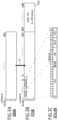
- FIGs. 3A-3C pictorially show a frame structure that can be used in system 100 ( FIG. 1 ) and by transceiver 110 ( FIG. 2 ) according to an example embodiment.
- the shown frame structure complies with the above-cited ITU-T G.709/Y.1331 Recommendation.
- ITU-T G.709/Y.1331 Recommendation A person of ordinary skill in the art will understand that other suitable frame structures may similarly be used in alternative embodiments of system 100.
- FIG. 3A pictorially shows an optical data unit ODUk that can be generated by frame generator 222 using the above-listed processing steps (A)-(C).
- the data of optical data unit ODUk are organized in 3824 columns and four rows, with each position containing one byte of data.
- FIG. 3B pictorially shows an optical transport unit OTUk that can be generated by frame generator 222 using the above-listed processing step (D).
- the frame structure of optical transport unit OTUk is based on the frame structure of optical data unit ODUk which is extended to contain 256 additional columns for an OTUk FEC data block 302.
- An OTU overhead OTU OH is located in row 1, columns 1 to 14, of optical data unit ODUk.
- the overhead bytes in row 1, columns 1 to 7, of OTU overhead OTU OH are used for the frame-alignment overhead, which is labeled in FIG. 3B as FA OH.
- the overhead bytes in row 1, columns 8 to 14, of OTU overhead OTU OH are used for the OTUk-specific overhead, which is labeled in FIG. 3B as OTUk OH.
- the FEC code used for generating the OTUk FEC data block 302 can be an FEC code specified in the above-cited ITU-T G.709/Y.1331 Recommendation or any other suitable (e.g., proprietary) FEC code.
- FIG. 3C pictorially shows a more-detailed (expanded) view of the OTU overhead OTU OH.
- Columns 1 to 6 of OTU OH are configured to carry a frame alignment signal FAS.
- Column 7 of OTU OH is configured to carry a multi-frame alignment signal MFAS.
- Columns 8 to 10 of OTU OH are configured to carry an overhead corresponding to the general communication channel GCC0.
- Columns 13 and 14 of OTU OH are configured to carry an overhead RES, which is reserved for proprietary use and future standardization.
- a more-detailed description of the various bytes of the OTU overhead OTU OH shown in FIG. 3C can be found, e.g., in the above-cited ITU-T G.709/Y.1331 Recommendation.
- At least one byte (e.g., column 14) of overhead RES can be used to carry a binary value that represents the error count determined by frame decoder 272 at the above-listed processing step (F).
- This binary value can be computed and used by controller 240 is described in more detail below in reference to FIGs. 5-12 .
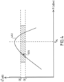
- FIG. 4 graphically illustrates example performance characteristics of system 100 according to an embodiment. More specifically, a curve 402 in the graph of FIG. 4 represents an example dependence of the quality factor Q 2 measured at the optical receiver 250 of a transceiver 110 located at one (e.g., West) end of link 150 as a function of output optical power of laser 232 of the corresponding transceiver 110 located at the other (e.g., East) end of link 150.
- Curve 402 has a maximum at the output power P NL .
- the quality factor Q 2 generally increases with an increase of the laser output power.
- the quality factor Q 2 generally decreases with an increase of the laser output power, primarily due to the increasing detrimental contributions of nonlinear optical effects in link 150.
- Target characteristics of a transmitter/receiver pair that communicate with one another over link 150 can be specified using a range of the quality-factor values located between Q 2 L and Q 2 U , where Q 2 L is the lower limit of the range, and Q 2 U is the upper limit of the range.
- the values of Q 2 L and Q 2 U are the design and/or configuration parameters of system 100 that may be selected and/or specified by the system operator based on the intended use of the system. Once selected, the values of Q 2 L and Q 2 U can be stored in controller 240 for further use in the pertinent algorithms and/or protocols employed, e.g., for configuring transceiver 110 for optimal performance as described in reference to FIGs. 5-12 .
- the values of Q 2 L and Q 2 U can be made applicable to multiple carrier wavelengths (optical WDM channels). In some embodiments, a different respective pair of Q 2 L and Q 2 U can be specified for each carrier wavelength (e.g., managed on a per-channel basis). In some embodiments, the Q 2 L and/or Q 2 U values can be made dependent on some other system-configuration parameters, such as the modulation format, the type of the used FEC code, the FEC-code rate, etc.
- the use of the quality factor Q 2 represents only one of many possible ways of specifying and/or attaining a desired (e.g., optimal) configuration of system 100.
- the optical signal-to-noise ratio (OSNR) or the bit error rate (BER) can similarly be used.
- OSNR optical signal-to-noise ratio
- BER bit error rate
- other suitable measures of transmission quality can alternatively be used.
- the BER is the most-direct indicator of the transmission quality. For example, due to the adverse effects of noise, nonlinearities, and dispersion, the waveforms of optical signals coupled into fibers typically become distorted when those optical signals arrive at the remote end of the fiber-optic link, such as link 150. As a result, bit errors are typically present when the receiver converts the optical signals into the corresponding electrical signals and then decodes the latter. A greater number of pre-FEC bit errors is therefore an indication of the poorer transmission quality, and vice versa.
- the quality factor Q 2 and BER have a one-to-one correspondence that can be expressed, e.g., as follows: (1)
- the OSNR is the ratio of the signal power to the noise power within a valid bandwidth.
- P NL see FIG. 4
- the changes of the OSNR and of the Q value expressed in decibel are approximately linearly proportional to one another.
- Eq. (2) gives the expression that can be used to convert the quality factor Q 2 into the Q value expressed in decibel, e.g., for relating the latter to the OSNR:
- Eqs. (1)-(2) can be used to program controller 240 to interconvert various possible quantitative measures of the end-to-end transmission performance of a wavelength channel in system 100.
- the term "measure of transmission quality” should be construed to cover each and any of: (i) the quality factor Q 2 ; (ii) the Q value expressed in decibel; (iii) the BER, e.g., expressed as the number of FEC-code-corrected errors per data frame; and (iv) the OSNR. These quantities can be inter-converted, e.g., in the above-explained manner. Furthermore, the term “measure of transmission quality” should also be construed to cover any other value or quantity that can be unambiguously mapped onto any one of those parameters. One or more of such "measures of transmission quality" (e.g., one per carrier wavelength, per transmission direction) can be used to configure and operate various embodiments of system 100, e.g., as further explained below.
- FIG. 5 shows a flowchart of a communication method 500 that can be used in transceiver 110 ( FIG. 2 ) according to an embodiment.
- method 500 is described in reference to the frame format shown in FIGs. 3A-3B .
- a person of ordinary skill in the art will understand that other suitable frame formats may similarly be used.
- receiver 250 ( FIG. 2 ) operates to receive an optical input signal 248 carrying a first data frame transmitted by the corresponding remote transceiver 110 (also see FIG. 1 ).
- frame decoder 272 of receiver 250 processes the first frame to recover the corresponding client data 298 encoded therein.
- This processing includes using the operative FEC code and the FEC data block 302 (see FIG. 3B ) of the first data frame to correct errors (if any) in the first data frame.
- This processing further includes reading information from the various overhead fields, such as the fields of OTU OH ( FIG. 3C ).
- sub-module 276 of frame decoder 272 counts the number of errors that have been corrected using the FEC code at step 504.
- Frame decoder 272 then provides the FEC error count, by way of control signal 236, to controller 240.
- controller 240 generates control signal 206 in response to the control signal 236 of step 506. More specifically, controller 240 generates control signal 206 in a manner that causes this control signal to carry a measure of transmission quality corresponding to the FEC error count of step 506.
- the measure of transmission quality may be any one of the quality factor Q 2 , the Q value expressed in decibel, the BER, the OSNR, or any other suitable quantity.
- controller 240 may be configured to: (i) convert the FEC error count of step 506 into the corresponding BER value, e.g., as known in the art; and (ii) convert the latter BER value into the corresponding measure of transmission quality, e.g., as explained above in reference to FIG. 4 and/or Eqs. (1)-(2).
- step 510 frame generator 226 of transmitter 210 generates a second data frame using the corresponding client data 202 and the measure of transmission quality provided thereto by control signal 206 generated at step 508.
- step 510 may include a sub-step of writing the provided measure of transmission quality into the designated field of OTU OH, such as the overhead RES (see FIG. 3C ) of the second data frame, said writing being performed using sub-module 224 of frame generator 226.
- Step 510 may also include a sub-step of generating the FEC data block 302 (see FIG. 3B ) for the second data frame using the operative FEC code.
- sub-module 274 of frame decoder 272 reads the measure of transmission quality from the designated field of OTU OH, such as the overhead RES (see FIG. 3C ) of the first data frame. Frame decoder 272 then provides this measure of transmission quality, by way of control signal 234, to controller 240.
- controller 240 At step 514, controller 240 generates control signal 244 in response to the control signal 234 of step 512. More specifically, controller 240 operates to generate control signal 244 that is configured to cause laser 232 of transmitter 210 to set (e.g., change) its optical output power based on the measure of transmission quality provided at step 512. Example embodiments of the sub-step of setting the optical output power of laser 232 that can be used to implement step 514 are described below in reference to FIGs. 6-12 .
- transmitter 210 uses the optical power set at step 514 to generate an optical output signal 212 carrying the second data frame generated at step 510. Transmitter 210 then operates to transmit the optical output signal 212 generated in this manner to the corresponding remote transceiver 110 (also see FIG. 1 ).
- FIG. 6 shows a flowchart of a control method 600 that can be used in transceiver 110 ( FIG. 2 ) according to an embodiment.
- method 600 is described in reference to an embodiment in which the measure of transmission quality is the quality factor Q 2 . Based on the provided description, a person of ordinary skill in the art will be able to make and use other embodiments, in which the measure of transmission quality is different from the quality factor Q 2 .
- Method 600 can be used in conjunction with method 500.
- Method 600 is generally directed at setting the output optical power of laser 232 in the local transmitter 210 such that (i) the output optical power is smaller than P NL and (ii) the corresponding remote receiver 250 is placed into an operating regime characterized by the quality factor Q 2 whose value is between the values of Q 2 L and Q 2 U (also see FIG. 4 ).
- the values of Q 2 L and Q 2 U are the design and/or configuration parameters and, as such, have fixed values for the purposes of method 600.
- the threshold power P NL is a system characteristic that can be determined within method 600, e.g., by appropriately analyzing the history of its execution generated and stored in the memory as explained in more detail below.
- Method 600 starts at step 602 during which the corresponding transceiver 110 is turned on, booted up, and brought online.
- Step 604 is configured to direct the processing of method 600 along two different processing paths depending on the encountered situation. More specifically, for the first install of transceiver 110, the processing of method 600 is directed to step 606. Otherwise, the processing of method 600 is directed to step 608. In the latter case, step 606 is performed after the completion of step 608.
- step 606 is described in reference to FIGs. 7-10 .
- step 608 is described in reference to FIGs. 11-12 .
- FIG. 7 shows a flowchart of step 606 according to an embodiment.
- controller 240 may store the history of its execution in a memory.
- each entry in the history may include the optical output power of laser 232 and the resulting value of the quality factor Q 2 obtained at the remote receiver 250 and communicated back to controller 240, e.g., using method 500 ( FIG. 5 ).
- the stored history can be used, e.g., to determine if an optimum configuration has been passed or missed during the power-adjustment process of step 606.
- Sub-step 702 is configured to direct the processing of step 606 along two different processing paths depending on whether or not the overhead of the incoming data frame contains a quality-factor (QF) value. If the corresponding remote receiver 250 has included a QF value in the frame overhead, then the processing of step 606 is directed to sub-step 706. Otherwise, the processing of step 606 is directed to sub-step 704.
- QF quality-factor
- step 704 is described in reference to FIG. 8 .
- Sub-steps 706, 708, and 712 are configured to direct the processing of step 606 along different processing paths depending on (i) the result of the comparison of the received QF value with the values of Q 2 L and Q 2 U and (ii) the result of the comparison of the corresponding output optical power of laser 232 with the threshold power P NL .
- step 606 is directed to sub-step 716. Otherwise, the processing of step 606 is directed to sub-step 708.
- step 606 If the received QF value is smaller than Q 2 L , and if the corresponding output optical power of laser 232 is greater than the threshold power P NL , then the processing of step 606 is directed to sub-step 714.
- step 606 If the received QF value is smaller than Q 2 L , and if the corresponding output optical power of laser 232 is smaller than the threshold power P NL , then the processing of step 606 is directed to sub-step 716.
- step 606 If the received QF value is between the values of Q 2 L and Q 2 U , then the processing of step 606 is directed to sub-step 710.
- controller 240 concludes that the output optical power of laser 232 is at an acceptable level, and proceeds to generate control signal 244 such that the output optical power of laser 232 remains unchanged.
- sub-step 714 An example embodiment of sub-step 714 is described in reference to FIG. 9 .
- sub-step 716 An example embodiment of sub-step 716 is described in reference to FIG. 10 .
- FIG. 8 shows a flowchart of sub-step 704 according to an embodiment.
- sub-step 802 of sub-step 704 it is determined whether or not the output optical power of laser 232 is set to P ref . If yes, then the processing of sub-step 704 is terminated. Otherwise, the processing of sub-step 704 is directed to sub-step 804.
- P ref is a fixed reference power.
- the value of P ref is a design parameter that defines the maximum power to be used while a QF value is not yet delivered from the corresponding remote transceiver 110 on the received data frame(s).
- sub-step 804 it is determined whether or not the output optical power of laser 232 is set to a last valid value of the output optical power. If yes, then the processing of sub-step 704 is terminated. Otherwise, the processing of sub-step 704 is directed to sub-step 806.
- the term "last valid value" refers to a recent output optical power that resulted in a QF value within the target range, i.e., between the values of Q 2 L and Q 2 U .
- a last valid value is typically stored in the memory of controller 240 and can be retrieved therefrom.
- controller 240 operates to generate control signal 244 such that the output optical power of laser 232 is increased by a relatively small increment.
- the increment can be determined as a fixed percentage of the difference between P ref and the present output optical power of laser 232.
- FIG. 9 shows a flowchart of sub-step 714 according to an embodiment.
- the power adjustment process corresponding to sub-step 714 is generally directed at gradually shifting the operating point along curve 402 toward a portion 404 of the curve located between the values of Q 2 L and Q 2 U at the power levels that are below the threshold power P NL (see FIG. 4 ).
- the term "gradually” refers to relatively small incremental changes that do not perturb too much the operation of other transceivers 110 transmitting in the same direction through link 150 on other carrier wavelengths.
- gradual changes are typically needed to maintain the overall operating stability of the corresponding WDM transceiver 102 in which individual transceivers 110 are configured for independent power adjustment using methods 500 and 600.
- controller 240 operates to generate control signal 244 such that the output optical power of laser 232 is decreased by a relatively small increment.
- the increment value can be a fixed parameter.
- sub-step 904 it is determined whether or not the overhead of the incoming data frame contains a QF value corresponding to the decreased output optical power that was set at sub-step 902. If the corresponding remote receiver 250 has included such a QF value in the frame overhead, then the processing of sub-step 714 is directed to sub-step 906. Otherwise, the processing of sub-step 714 is directed to sub-step 704, a copy of which is incorporated into the processing flow as shown in FIG. 9 (also see FIG. 8 ).
- the QF value is read from the overhead of the received data frame. Controller 240 then generates a corresponding entry for the history stored in the memory. This entry contains (i) the QF value read from the overhead of the received data frame and (ii) the corresponding output optical power of laser 232 that was set at sub-step 902.
- sub-step 908 it is determined whether or not the output optical power of laser 232 that was set at sub-step 902 is below the threshold power P NL . If yes, then the processing of sub-step 714 is terminated. Otherwise, the processing of sub-step 714 is returned back to sub-step 902.
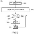
- FIG. 10 shows a flowchart of sub-step 716 according to an embodiment.
- the power adjustment process corresponding to sub-step 716 has a similar purpose to that of sub-step 714.
- the staring point on curve 402 for sub-step 716 is different from the staring point on curve 402 for sub-step 714 due to a different processing path through sub-steps 706, 708, and 712.
- the execution of sub-step 716 may cause the output optical power of laser 232 to decrease or increase, whereas the execution of sub-step 714 causes the output optical power of laser 232 only to decrease.
- the QF value is read from the overhead of the received data frame.
- controller 240 uses the QF value of step 1002 to determine a next possible value NewP of the output optical power of laser 232.
- this next possible value can be a power that shifts the operating point along curve 402 ( FIG. 4 ) by a power increment needed to place the operating point within portion 404 of curve 402 (see FIG. 4 ).
- Controller 240 may need to access the history stored in its memory to make this determination of the next possible value of the output optical power of laser 232.
- Sub-step 1006 serves as a check against unacceptably large changes of the output optical power of laser 232.
- controller 240 operates to (i) determine the power increment ⁇ P that is needed to reach the possible value of the output power computed at step 1004 and (ii) compare ⁇ P with a fixed threshold value MaxStep.
- the fixed threshold value MaxStep is an algorithm parameter that is judged to guarantee the "gradual" pace of the power changes.
- sub-step 1006 If it is determined at sub-step 1006 that ⁇ P > MaxStep, then the processing of sub-step 716 is directed to sub-step 1008. Otherwise, the processing of sub-step 716 is directed to sub-step 1010.
- next possible value NewP computed at step 1004 is replaced by a different value of NewP that is computed by applying the increment MaxStep to the present output power instead of the power increment ⁇ P, which was judged at sub-step 1006 to be too large.
- controller 240 operates to generate control signal 244 such that the output optical power of laser 232 is changed to NewP.
- the value of NewP can be the value computed at sub-step 1004 or the value computed at sub-step 1008.
- FIG. 11 shows a flowchart of step 608 according to an embodiment.
- step 608 is implemented by modifying sub-step 704 shown in FIG. 8 , with the modification being the replacement of sub-step 806 by sub-step 1102.
- the reader is referred to the description of FIG. 8 .
- An example embodiment of sub-step 1102 is described in reference to FIG. 12 .
- FIG. 12 shows a flowchart of sub-step 1102 according to an embodiment.
- the processing flow of sub-step 1102 incorporates two copies of sub-step 704 and a copy of sub-step 714. For the description of the latter two, the reader is referred to the description of FIGs. 8 and 9 , respectively.
- sub-step 1202 it is determined whether or not the overhead of a first received data frame contains a QF value. If the corresponding remote receiver 250 has included such a QF value in the frame overhead, then the processing of sub-step 1102 is directed to sub-step 1204. Otherwise, the processing of sub-step 1102 is directed to a first copy of sub-step 704.
- the QF value is read from the overhead of the first received data frame. Controller 240 then generates a corresponding entry for the history stored in the memory. This entry contains (i) the QF value read from the overhead of the first received data frame and (ii) the corresponding output optical power of laser 232.
- controller 240 operates to generate control signal 244 such that the output optical power of laser 232 is increased by a relatively small increment.
- the increment can be smaller than MaxStep (see FIG. 10 ).
- sub-step 1208 it is determined whether or not the overhead of a second received data frame contains a QF value. If the corresponding remote receiver 250 has included such a QF value in the frame overhead, then the processing of sub-step 1102 is directed to sub-step 1210. Otherwise, the processing of sub-step 1102 is directed to a second copy of sub-step 704.
- the QF value is read from the overhead of the second received data frame. Controller 240 then generates a corresponding entry for the history stored in the memory. This entry contains (i) the QF value read from the overhead of the second received data frame and (ii) the corresponding increased output optical power of laser 232 that was set at sub-step 1206.
- controller 240 uses the history entries stored in the memory at sub-steps 1204 and 1208 to compute the QF slope S as follows: (3) where ( QF 1 , P 1 ) is the history entry stored in the memory at sub-step 1204; and ( QF 2 , P 2 ) is the history entry stored in the memory at sub-step 1208.
- controller 240 determines the sign of the QF slope S computed at sub-step 1212. If the sign of S is negative, then the processing of sub-step 1102 is directed to sub-step 714, a copy of which is incorporated into the processing flow of sub-step 1102. Otherwise, the copy of sub-step 714 is bypassed, and the processing of sub-step 1102 is terminated as indicated in FIG. 12 .
- an apparatus e.g., 100, FIG. 1 ; 110, FIG. 2
- an optical data receiver e.g., 250, FIG. 2
- an optical data transmitter e.g., 210, FIG. 2
- an electronic controller e.g., 240, FIG. 2
- the optical data receiver including a photodetector (e.g., 262, FIG. 2 ) configured to detect an optical input signal (e.g., 248, FIG.
- the optical data transmitter including a laser (e.g., 232, FIG. 2 ) configured to generate a carrier wavelength for an optical output signal (e.g., 212, FIG. 2 );
- the optical data receiver comprises a frame decoder (e.g., 272, FIG. 2 ) configured to read a first value of a measure of transmission quality from an overhead (e.g., OTUk OH, FIG. 3B ) of the first data frame, the measure of transmission quality representing an error rate at which an FEC code used at a remote receiver encounters errors in data transmitted using the optical output signal; and wherein the electronic controller is configured to change an optical output power of the laser (e.g., using 244, FIG. 2 ) in response to the first value of the measure of transmission quality provided thereto (e.g., by way of 234, FIG. 2 ) by the frame decoder.
- the optical data receiver comprises a frame decoder (e.g., 272, FIG. 2 ) configured to read a first value of a measure
- the measure of transmission quality is one of: (i) a quality factor Q 2 corresponding to the error rate (e.g., Eq. (1)); (ii) a Q value derived from the quality factor Q 2 and expressed in decibel (e.g., Eq. (2)); (iii) a number of errors per data frame corrected by the FEC code; and (iv) an optical signal-to-noise ratio corresponding to the quality factor Q 2 .
- the frame decoder is further configured to count (e.g., at 276, FIG. 2 ) a number of errors corrected in the first data frame using an FEC data block (e.g., 302, FIG. 3B ) thereof; wherein the electronic controller is configured to compute a second value of the measure of transmission quality using the number of errors counted by the frame decoder; wherein the optical data transmitter comprises a frame generator (e.g., 222, FIG. 2 ) configured to write (e.g., using 206 and 224, FIG. 2 ) the second value of the measure of transmission quality into an overhead (e.g., OTUk OH, FIG. 3B ) of a second data frame; and wherein the optical data transmitter is configured to cause the optical output signal to carry the second data frame.
- a frame generator e.g., 222, FIG. 2
- the optical data transmitter comprises a frame generator (e.g., 222, FIG. 2 ) configured to write (e.g., using 206 and 224
- the frame generator is further configured to include an FEC data block (e.g., 302, FIG. 3B ) into the second data frame, the FEC data block of the second data frame being computed using the overhead of the second data frame and a payload of the second data frame, the overhead being configured to carry one or more values of the measure of transmission quality.
- FEC data block e.g., 302, FIG. 3B
- the apparatus further comprises a plurality of optical data transmitters (e.g., 110 1W -110 NW , FIG. 1 ), each configured to use a different respective carrier wavelength (e.g., ⁇ 1 - ⁇ N , FIG. 1 ), the optical data transmitter being one of the plurality.
- a plurality of optical data transmitters e.g., 110 1W -110 NW , FIG. 1
- each respective carrier wavelength e.g., ⁇ 1 - ⁇ N , FIG. 1
- the optical data transmitter being one of the plurality.
- the apparatus further comprises a plurality of optical data receivers (e.g., 110 1W -110 NW , FIG. 1 ), each configured to receive a different respective carrier wavelength (e.g., ⁇ 1 - ⁇ N , FIG. 1 ), the optical data receiver being one of the plurality.
- a plurality of optical data receivers e.g., 110 1W -110 NW , FIG. 1
- each respective carrier wavelength e.g., ⁇ 1 - ⁇ N , FIG. 1
- the optical data receiver being one of the plurality.
- the electronic controller is configured to change the optical output power of the laser (e.g., using 600, FIG. 6 ) to cause a value of the measure of transmission quality from an overhead of another data frame received by the optical data receiver from the remote receiver at a later time to be within a predetermined fixed range of values (e.g., between Q 2 L and Q 2 U , FIG. 4 ).
- the electronic controller is configured to dynamically change the optical output power of the laser (e.g., using 600, FIG. 6 ) in response to a sequence of values of the measure of transmission quality, each of said values being read from an overhead of a different respective data frame carried by the optical input signal.
- the first data frame comprises an optical transport unit (e.g., OTUk, FIG. 3B ) generated in accordance with an ITU-T G.709/Y.1331 Recommendation.
- OTUk optical transport unit
- the electronic controller is configured to change the optical output power of the laser by an increment determined in response to the first value of the measure of transmission quality, the increment being smaller than or equal to a predetermined fixed value (e.g., MaxStep, FIG. 10 ).
- the electronic controller is configured to store therein a history of power changes, each entry in the history including a respective optical output power of the laser and a corresponding value of the measure of transmission quality received from the remote receiver.
- an apparatus e.g., 100, FIG. 1 ; 110, FIG. 2
- an optical data receiver e.g., 250, FIG. 2
- an optical data transmitter e.g., 210, FIG. 2
- an electronic controller e.g., 240, FIG. 2
- the optical data receiver including a photodetector (e.g., 262, FIG. 2 ) configured to detect an optical input signal (e.g., 248, FIG.
- the optical data transmitter including a laser (e.g., 232, FIG. 2 ) configured to generate a carrier wavelength for an optical output signal (e.g., 212, FIG. 2 ) carrying a second data frame;
- the optical data receiver comprises a frame decoder (e.g., 272, FIG. 2 ) configured to count (e.g., at 276, FIG. 2 ) a number of errors corrected in the first data frame using an FEC data block (e.g., 302, FIG.
- the electronic controller is configured to compute a first value of a measure of transmission quality using the number of errors counted by the frame decoder; and wherein the optical data transmitter comprises a frame generator (e.g., 222, FIG. 2 ) configured to write (e.g., using 206 and 224, FIG. 2 ) the first value of the measure of transmission quality into an overhead (e.g., OTUk OH, FIG. 3B ) of the second data frame.
- a frame generator e.g., 222, FIG. 2
- the optical data transmitter comprises a frame generator (e.g., 222, FIG. 2 ) configured to write (e.g., using 206 and 224, FIG. 2 ) the first value of the measure of transmission quality into an overhead (e.g., OTUk OH, FIG. 3B ) of the second data frame.
- the measure of transmission quality is one of: (i) a quality factor Q 2 corresponding to the number of errors (e.g., Eq. (1)); (ii) a Q value derived from quality factor Q 2 and expressed in decibel (e.g., Eq. (2)); (iii) the number of errors; and (iv) an optical signal-to-noise ratio corresponding to the quality factor Q 2 .
- the frame generator is further configured to include an FEC data block (e.g., 302, FIG. 3B ) into the second data frame, the FEC data block of the second data frame being computed using the overhead of the second data frame and a payload of the second data frame, the overhead being configured to carry one or more values of the measure of transmission quality.
- FEC data block e.g., 302, FIG. 3B
- the frame decoder is configured to read a second value of the measure of transmission quality from an overhead (e.g., OTUk OH, FIG. 3B ) of the first data frame; and wherein the electronic controller is configured to change an optical output power of the laser (e.g., using 244, FIG. 2 ) in response to the second value of the measure of transmission quality provided thereto (e.g., by way of 234, FIG. 2 ) by the frame decoder.
- an overhead e.g., OTUk OH, FIG. 3B
- the electronic controller is configured to change an optical output power of the laser (e.g., using 244, FIG. 2 ) in response to the second value of the measure of transmission quality provided thereto (e.g., by way of 234, FIG. 2 ) by the frame decoder.
- a communication method (e.g., 500, FIG. 5 ) that can be carried out at an optical transceiver (e.g., 110, FIG. 2 ), the method comprising the steps of: receiving (e.g., 502, FIG. 5 ) an optical input signal carrying a first data frame; decoding (e.g., 504, FIG. 5 ) the first data frame to read (e.g., 512, FIG. 5 ) a first value of a measure of transmission quality from an overhead (e.g., OTUk OH, FIG.
- an optical transceiver e.g., 110, FIG. 2
- the method comprising the steps of: receiving (e.g., 502, FIG. 5 ) an optical input signal carrying a first data frame; decoding (e.g., 504, FIG. 5 ) the first data frame to read (e.g., 512, FIG. 5 ) a first value of a measure of transmission quality from an overhead (e.g., OTUk OH, FIG
- the measure of transmission quality representing an error rate at which an FEC code used at a remote receiver encounters errors in data received from the optical transceiver; and changing (e.g., 514, FIG. 5 ) an optical output power of a laser (e.g., 232, FIG. 2 ) in response to the first value of the measure of transmission quality, the laser being configured to generate a carrier wavelength for an optical output signal directed to the remote receiver.
- a laser e.g., 232, FIG. 2
- the method further comprises the steps of: counting (e.g., 506, FIG. 5 ) a number of errors corrected in the first data frame using an FEC data block (e.g., 302, FIG. 3B ) thereof; computing (e.g., 508, FIG. 5 ) a second value of the measure of transmission quality using the number of errors; writing (e.g., 510, FIG. 5 ) the second value of the measure of transmission quality into an overhead (e.g., OTUk OH, FIG. 3B ) of a second data frame; and transmitting (e.g., 516, FIG. 5 ) the optical output signal to the remote receiver, the optical output signal being configured to carry the second data frame.
- counting e.g., 506, FIG. 5
- an FEC data block e.g., 302, FIG. 3B
- computing e.g., 508, FIG. 5
- a second value of the measure of transmission quality using the number of errors
- writing e.g., 510, FIG.
- the method further comprises the step of including an FEC data block (e.g., 302, FIG. 3B ) into the second data frame, the FEC data block of the second data frame being computed using the overhead of the second data frame and a payload of the second data frame, the overhead being configured to carry one or more values of the measure of transmission quality.
- an FEC data block e.g., 302, FIG. 3B
- figure numbers and/or figure reference labels in the claims is intended to identify one or more possible embodiments of the claimed subject matter in order to facilitate the interpretation of the claims. Such use is not to be construed as necessarily limiting the scope of those claims to the embodiments shown in the corresponding figures.
- Couple refers to any manner known in the art or later developed in which energy is allowed to be transferred between two or more elements, and the interposition of one or more additional elements is contemplated, although not required. Conversely, the terms “directly coupled,” “directly connected,” etc., imply the absence of such additional elements.
- the term compatible means that the element communicates with other elements in a manner wholly or partially specified by the standard, and would be recognized by other elements as sufficiently capable of communicating with the other elements in the manner specified by the standard.
- the compatible element does not need to operate internally in a manner specified by the standard.
- program storage devices e.g., digital data storage media, which are machine or computer readable and encode machine-executable or computer-executable programs of instructions where said instructions perform some or all of the steps of methods described herein.
- the program storage devices may be, e.g., digital memories, magnetic storage media such as a magnetic disks or tapes, hard drives, or optically readable digital data storage media.
- the embodiments are also intended to cover computers programmed to perform said steps of methods described herein.
- processors may be provided through the use of dedicated hardware as well as hardware capable of executing software in association with appropriate software.
- the functions may be provided by a single dedicated processor, by a single shared processor, or by a plurality of individual processors, some of which may be shared.
- processor or “controller” should not be construed to refer exclusively to hardware capable of executing software, and may implicitly include, without limitation, digital signal processor (DSP) hardware, network processor, application specific integrated circuit (ASIC), field programmable gate array (FPGA), read only memory (ROM) for storing software, random access memory (RAM), and non volatile storage.
- DSP digital signal processor
- ASIC application specific integrated circuit
- FPGA field programmable gate array
- ROM read only memory
- RAM random access memory
- non volatile storage Other hardware, conventional and/or custom, may also be included.
- any switches shown in the figures are conceptual only. Their function may be carried out through the operation of program logic, through dedicated logic, through the interaction of program control and dedicated logic, or even manually, the particular technique being selectable by the implementer as more specifically understood from the context.
- circuitry may refer to one or more or all of the following: (a) hardware-only circuit implementations (such as implementations in only analog and/or digital circuitry); (b) combinations of hardware circuits and software, such as (as applicable): (i) a combination of analog and/or digital hardware circuit(s) with software/firmware and (ii) any portions of hardware processor(s) with software (including digital signal processor(s)), software, and memory(ies) that work together to cause an apparatus, such as a mobile phone or server, to perform various functions); and (c) hardware circuit(s) and or processor(s), such as a microprocessor(s) or a portion of a microprocessor(s), that requires software (e.g., firmware) for operation, but the software may not be present when it is not needed for operation.”
- This definition of circuitry applies to all uses of this term in this application, including in any claims.
- circuitry also covers an implementation of merely a hardware circuit or processor (or multiple processors) or portion of a hardware circuit or processor and its (or their) accompanying software and/or firmware.
- circuitry also covers, for example and if applicable to the particular claim element, a baseband integrated circuit or processor integrated circuit for a mobile device or a similar integrated circuit in server, a cellular network device, or other computing or network device.
- any block diagrams herein represent conceptual views of illustrative circuitry embodying the principles of the disclosure.
- any flow charts, flow diagrams, state transition diagrams, pseudo code, and the like represent various processes which may be substantially represented in computer readable medium and so executed by a computer or processor, whether or not such computer or processor is explicitly shown.
Landscapes
- Engineering & Computer Science (AREA)
- Computer Networks & Wireless Communication (AREA)
- Signal Processing (AREA)
- Physics & Mathematics (AREA)
- Electromagnetism (AREA)
- Optics & Photonics (AREA)
- Optical Communication System (AREA)
Claims (12)
- Vorrichtung, die einen optischen Datensender (210) und eine elektronische Steuerung (240) umfasst, wobei der optische Datensender einen Laser (232) beinhaltet, der dazu ausgelegt ist, eine Trägerwellenlänge für ein optisches Ausgangssignal (212) zu erzeugen, das über eine Spanne von Lichtwellenleitern an einen entfernten Empfänger gesendet wird;wobei die Vorrichtung dazu ausgelegt ist, einen ersten Wert eines Maßes einer Übertragungsqualität zu lesen, wobei das Maß der Übertragungsqualität eine Fehlerrate repräsentiert, mit der ein am entfernten Empfänger verwendeter FEC-Code auf Fehler in Daten trifft, die unter Verwendung des optischen Ausgangssignals übertragen werden; undwobei die elektronische Steuerung dazu ausgelegt ist, in Reaktion auf den ersten Wert des Maßes der Übertragungsqualität eine optische Ausgangsleistung des Lasers zu ändern,dadurch gekennzeichnet, dass die Vorrichtung ferner einen optischen Datenempfänger (250) umfasst, wobei der optische Datenempfänger (250) einen Photodetektor (262) beinhaltet, der dazu ausgelegt ist, ein optisches Eingangssignal (248) zu detektieren, das einen ersten Datenframe transportiert,wobei der optische Datenempfänger (250) einen Framedecodierer (272) umfasst, der dazu ausgelegt ist, den ersten Wert des Maßes der Übertragungsqualität im ersten Datenframe zu lesen,wobei der erste Wert des Maßes der Übertragungsqualität der elektronischen Steuerung (240) vom Framedecodierer (272) bereitgestellt wird, wobei die Steuerung zwischen dem optischen Datenempfänger (250) und dem optischen Datensender (210) verbunden ist,wobei der Framedecodierer ferner dazu ausgelegt ist, eine Anzahl von Fehlern zu zählen, die im ersten Datenframe unter Verwendung eines FEC-Datenblocks (302) davon korrigiert wurden;wobei die elektronische Steuerung dazu ausgelegt ist, einen zweiten Wert des Maßes der Übertragungsqualität unter Verwendung der Anzahl von Fehlern, die vom Framedecodierer gezählt wurden, zu berechnen;wobei der optische Datensender einen Framegenerator (222) umfasst, der dazu ausgelegt ist, den zweiten Wert des Maßes der Übertragungsqualität in einen zweiten Datenframe zu schreiben; undwobei der optische Datensender dazu ausgelegt ist, das optische Ausgangssignal zu veranlassen, den zweiten Datenframe über die Spanne von Lichtwellenleitern zum entfernten Empfänger zu transportieren.
- Vorrichtung nach Anspruch 1, wobei das Maß der Übertragungsqualität eines von Folgendem ist:ein Qualitätsfaktor Q2, der der Fehlerrate entspricht;ein Q-Wert, der aus dem Qualitätsfaktor Q2 abgeleitet und in Dezibel ausgedrückt ist;eine Anzahl von Fehlern pro Datenframe, die vom FEC-Code korrigiert wurden; undein optisches Signal-Rauschen-Verhältnis, das dem Qualitätsfaktor Q2 entspricht.
- Vorrichtung nach Anspruch 1, wobei der Framegenerator ferner dazu ausgelegt ist, einen FEC-Datenblock (302) in den zweiten Datenframe einzubinden, wobei der FEC-Datenblock des zweiten Datenframes unter Verwendung eines Overheads des zweiten Datenframes und von Nutzdaten des zweiten Datenframes berechnet wird, wobei der Overhead dazu ausgelegt ist, einen oder mehrere Werte des Maßes der Übertragungsqualität zu transportieren.
- Vorrichtung nach Anspruch 1, die ferner eine Vielzahl von optischen Datensendern (1101W-110NW) umfasst, von denen jeder dazu ausgelegt ist, jeweilige verschiedene Trägerwellenlängen zu verwenden, wobei der optische Datensender einer der Vielzahl ist.
- Vorrichtung nach Anspruch 1, die ferner eine Vielzahl von optischen Datenempfängern (1101W-110NW) umfasst, von denen jeder dazu ausgelegt ist, jeweilige verschiedene Trägerwellenlängen zu empfangen, wobei der optische Datenempfänger einer der Vielzahl ist.
- Vorrichtung nach Anspruch 1, wobei die elektronische Steuerung dazu ausgelegt ist, die optische Ausgangsleistung des Lasers zu ändern, um einen Wert des Maßes der Übertragungsqualität aus einem anderen Datenframe, der vom optischen Datenempfänger zu einer späteren Zeit vom entfernten Empfänger empfangen wird, zu veranlassen, innerhalb eines vorbestimmten festen Wertebereichs zu liegen.
- Vorrichtung nach Anspruch 1, wobei die elektronische Steuerung dazu ausgelegt ist, die optische Ausgangsleistung des Lasers in Reaktion auf eine Folge von Werten des Maßes der Übertragungsqualität dynamisch zu ändern, wobei jeder der Werte aus einem jeweiligen anderen Datenframe gelesen wird, der vom optischen Eingangssignal transportiert wird.
- Vorrichtung nach Anspruch 1, wobei der erste Datenframe eine optische Transporteinheit umfasst, die gemäß einer Empfehlung aus ITU-T G.709/Y.1331 erzeugt wird.
- Vorrichtung nach Anspruch 1, wobei die elektronische Steuerung dazu ausgelegt ist, die optische Ausgangsleistung des Lasers um ein Inkrement zu ändern, das in Reaktion auf den ersten Wert des Maßes der Übertragungsqualität bestimmt wird, wobei das Inkrement kleiner als oder gleich einem vorbestimmten festen Wert ist.
- Vorrichtung nach Anspruch 1, wobei die elektronische Steuerung dazu ausgelegt ist, darin einen Verlauf von Leistungsänderungen zu speichern, wobei jeder Eintrag im Verlauf eine jeweilige optische Ausgangsleistung des Lasers und eines entsprechenden Wertes des Maßes der Übertragungsqualität, der vom entfernten Empfänger empfangen wird, beinhaltet.
- Kommunikationsverfahren an einem optischen Sendeempfänger, das Folgendes umfasst:Lesen (512) eines ersten Wertes eines Maßes einer Übertragungsqualität, wobei das Maß der Übertragungsqualität eine Fehlerrate repräsentiert, mit der ein an einem entfernten Empfänger verwendeter FEC-Code auf Fehler in Daten trifft, die vom optischen Sendeempfänger empfangen werden; undÄndern (514) einer optischen Ausgangsleistung eines Lasers (232) in Reaktion auf den ersten Wert des Maßes der Übertragungsqualität, wobei der Laser dazu ausgelegt ist, eine Trägerwellenlänge für ein optisches Ausgangssignal zu erzeugen, das zum entfernten Empfänger geleitet wird,dadurch gekennzeichnet, dass das Kommunikationsverfahren ferner Folgendes umfasst:Empfangen (502) eines optischen Eingangssignals, das den ersten Datenframe transportiert;Decodieren (504) des ersten Datenframes, um den ersten Wert des Maßes der Übertragungsqualität aus dem ersten Datenframe zu lesen;Zählen (506) einer Anzahl von Fehlern, die im ersten Datenframe unter Verwendung eines FEC-Datenblocks (302) davon korrigiert wurden;Berechnen (508) eines zweiten Wertes des Maßes der Übertragungsqualität unter Verwendung der Anzahl von Fehlern;Schreiben (510) des zweiten Wertes des Maßes der Übertragungsqualität in den zweiten Datenframe; undÜbertragen (516) des optischen Ausgangssignals zum entfernten Empfänger, wobei das optische Ausgangssignal dazu ausgelegt ist, den zweiten Datenframe zu transportieren.
- Kommunikationsverfahren nach Anspruch 11, das ferner das Einbinden eines FEC-Datenblocks (302) in den zweiten Datenframe umfasst, wobei der FEC-Datenblock des zweiten Datenframes unter Verwendung eines Overheads des zweiten Datenframes und von Nutzdaten des zweiten Datenframes berechnet wird, wobei der Overhead dazu ausgelegt ist, einen oder mehrere Werte des Maßes der Übertragungsqualität zu transportieren.
Priority Applications (2)
| Application Number | Priority Date | Filing Date | Title |
|---|---|---|---|
| EP18305689.4A EP3579459B1 (de) | 2018-06-06 | 2018-06-06 | Kommunikationssystem mit verwendung von selbstabstimmenden optischen sendeempfängern |
| US16/427,514 US10778336B2 (en) | 2018-06-06 | 2019-05-31 | Communication system employing self-tuning optical transceivers |
Applications Claiming Priority (1)
| Application Number | Priority Date | Filing Date | Title |
|---|---|---|---|
| EP18305689.4A EP3579459B1 (de) | 2018-06-06 | 2018-06-06 | Kommunikationssystem mit verwendung von selbstabstimmenden optischen sendeempfängern |
Publications (2)
| Publication Number | Publication Date |
|---|---|
| EP3579459A1 EP3579459A1 (de) | 2019-12-11 |
| EP3579459B1 true EP3579459B1 (de) | 2024-12-18 |
Family
ID=62748881
Family Applications (1)
| Application Number | Title | Priority Date | Filing Date |
|---|---|---|---|
| EP18305689.4A Active EP3579459B1 (de) | 2018-06-06 | 2018-06-06 | Kommunikationssystem mit verwendung von selbstabstimmenden optischen sendeempfängern |
Country Status (2)
| Country | Link |
|---|---|
| US (1) | US10778336B2 (de) |
| EP (1) | EP3579459B1 (de) |
Families Citing this family (3)
| Publication number | Priority date | Publication date | Assignee | Title |
|---|---|---|---|---|
| US20210359764A1 (en) * | 2018-09-27 | 2021-11-18 | Nec Corporation | Optical transmitter and optical receiver |
| JP7423934B2 (ja) * | 2019-08-16 | 2024-01-30 | ソニーグループ株式会社 | 通信装置、通信方法、及び通信プログラム |
| EP4109790B1 (de) * | 2021-06-23 | 2024-07-31 | Alcatel Submarine Networks | Abstimmung der datenratenkapazität optischer transceiver |
Family Cites Families (15)
| Publication number | Priority date | Publication date | Assignee | Title |
|---|---|---|---|---|
| US6433904B1 (en) * | 1999-07-27 | 2002-08-13 | Sycamore Networks, Inc. | Method and apparatus for improving transmission performance over wavelength division multiplexed optical communication links using forward error correction coding |
| US6735725B1 (en) * | 2000-09-29 | 2004-05-11 | Nortel Networks Limited | Method and apparatus for performance management of a multiplexed transmission system |
| US7149424B2 (en) | 2002-08-22 | 2006-12-12 | Siemens Communications, Inc. | Method and device for evaluating and improving the quality of transmission of a telecommunications signal through an optical fiber |
| JP2005341392A (ja) * | 2004-05-28 | 2005-12-08 | Fujitsu Ltd | 光伝送装置、光伝送システムおよび分散補償方法 |
| US7609981B2 (en) * | 2005-09-07 | 2009-10-27 | Alcatel-Lucent Usa Inc. | Deliberate signal degradation for optimizing receiver control loops |
| US8620156B2 (en) | 2010-09-21 | 2013-12-31 | Adva Optical Networking Se | Method and apparatus for performing an automatic power adjustment for an optical signal |
| US20170279533A1 (en) | 2016-03-22 | 2017-09-28 | Menara Networks, Inc. | Pluggable optical transceiver interface module |
| US9071364B1 (en) | 2011-10-18 | 2015-06-30 | Clariphy Communications, Inc. | Coherent optical transceiver with programmable application modes |
| JP5987600B2 (ja) * | 2012-09-25 | 2016-09-07 | 富士通株式会社 | 光受信装置、光伝送システム及びスパンロスモニタ方法 |
| US9414135B2 (en) | 2013-12-24 | 2016-08-09 | Nec Corporation | Flexible-client, flexible-line interface transponder |
| US9331780B1 (en) | 2014-05-11 | 2016-05-03 | Google Inc. | Systems and methods for adaptive energy utilization of optical interconnection networks |
| US9712899B2 (en) | 2014-12-11 | 2017-07-18 | Alcatel Lucent | Hybrid optical switch for software-defined networking |
| US9647782B2 (en) | 2014-12-19 | 2017-05-09 | Alcatel Lucent | Frame synchronization for data transmission over an optical network |
| US20160373186A1 (en) * | 2015-06-16 | 2016-12-22 | Lenovo Enterprise Solutions (Singapore) Pte. Ltd. | Compensating for optical signal degradation |
| US10171169B2 (en) | 2016-06-07 | 2019-01-01 | Ciena Corporation | Software programmable flexible and dynamic optical transceivers |
-
2018
- 2018-06-06 EP EP18305689.4A patent/EP3579459B1/de active Active
-
2019
- 2019-05-31 US US16/427,514 patent/US10778336B2/en active Active
Also Published As
| Publication number | Publication date |
|---|---|
| EP3579459A1 (de) | 2019-12-11 |
| US20190379457A1 (en) | 2019-12-12 |
| US10778336B2 (en) | 2020-09-15 |
Similar Documents
| Publication | Publication Date | Title |
|---|---|---|
| US10284323B2 (en) | Optical transceiver with external laser source | |
| US9225456B2 (en) | Post-transient gain control of optical amplifiers | |
| US20110013911A1 (en) | High-speed optical transponder systems | |
| US9523867B2 (en) | Off quadrature biasing of Mach Zehnder modulator for improved OSNR performance | |
| US20080063028A1 (en) | Photonics-based Multi-band Wireless Communication Methods | |
| US20080063411A1 (en) | Photonics-based Multi-band Wireless Communication System | |
| US9641252B2 (en) | Method of optimizing optical signal quality in an optical communications link, optical network element and optical communications link | |
| US9236949B1 (en) | Laser transceiver with improved bit error rate | |
| US10778336B2 (en) | Communication system employing self-tuning optical transceivers | |
| Pachnicke et al. | Tunable WDM-PON system with centralized wavelength control | |
| CN109196796B (zh) | 光通信 | |
| US9998216B2 (en) | Skew measurement in an optical coherent transponder | |
| US9264788B2 (en) | Inter-channel spectral shaping in optical ring networks | |
| Meseguer et al. | Experimental assessment of capacity prediction from G-SNR measurements for submarine systems | |
| US20060188267A1 (en) | System and method for suppression of stimulated Brillouin scattering in optical transmission communications | |
| EP2840728B1 (de) | Optische Senderanordnung für passives optisches Netzwerk | |
| US9614623B2 (en) | High bandwidth photodetector current replicator | |
| EP3675390B1 (de) | Überwachung der optischen leistung von kommunikationssignalen unter verwendung von anzeichen eines polarisationsabhängigen verlustes beim empfänger | |
| US9838118B2 (en) | Skew compensation in an optical coherent transponder | |
| US11563300B2 (en) | Suppressing signal noise on an optical fiber | |
| US9553420B1 (en) | Current amplification to improve optical amplifier performance | |
| US9509113B2 (en) | Transient gain cancellation for optical amplifiers | |
| Ten et al. | 1.6 Tb/s (40× 40 Gb/s) transmission over 1200 km of field-deployed dispersion-managed fiber | |
| WO2008033722A2 (en) | Photonics-based multi-band wireless communication methods or systems | |
| EP0734127A1 (de) | Einrichtung zur digitalen Übertragung über Lichtleitfasern |
Legal Events
| Date | Code | Title | Description |
|---|---|---|---|
| PUAI | Public reference made under article 153(3) epc to a published international application that has entered the european phase |
Free format text: ORIGINAL CODE: 0009012 |
|
| STAA | Information on the status of an ep patent application or granted ep patent |
Free format text: STATUS: THE APPLICATION HAS BEEN PUBLISHED |
|
| AK | Designated contracting states |
Kind code of ref document: A1 Designated state(s): AL AT BE BG CH CY CZ DE DK EE ES FI FR GB GR HR HU IE IS IT LI LT LU LV MC MK MT NL NO PL PT RO RS SE SI SK SM TR |
|
| AX | Request for extension of the european patent |
Extension state: BA ME |
|
| STAA | Information on the status of an ep patent application or granted ep patent |
Free format text: STATUS: REQUEST FOR EXAMINATION WAS MADE |
|
| 17P | Request for examination filed |
Effective date: 20200612 |
|
| RBV | Designated contracting states (corrected) |
Designated state(s): AL AT BE BG CH CY CZ DE DK EE ES FI FR GB GR HR HU IE IS IT LI LT LU LV MC MK MT NL NO PL PT RO RS SE SI SK SM TR |
|
| STAA | Information on the status of an ep patent application or granted ep patent |
Free format text: STATUS: EXAMINATION IS IN PROGRESS |
|
| 17Q | First examination report despatched |
Effective date: 20211202 |
|
| REG | Reference to a national code |
Free format text: PREVIOUS MAIN CLASS: H04B0010077000 Ref country code: DE Ref legal event code: R079 Ref document number: 602018077664 Country of ref document: DE Ipc: H04J0014020000 |
|
| GRAP | Despatch of communication of intention to grant a patent |
Free format text: ORIGINAL CODE: EPIDOSNIGR1 |
|
| STAA | Information on the status of an ep patent application or granted ep patent |
Free format text: STATUS: GRANT OF PATENT IS INTENDED |
|
| RIC1 | Information provided on ipc code assigned before grant |
Ipc: H04B 10/079 20130101ALI20240624BHEP Ipc: H04B 10/077 20130101ALI20240624BHEP Ipc: H04J 14/02 20060101AFI20240624BHEP |
|
| INTG | Intention to grant announced |
Effective date: 20240716 |
|
| GRAF | Information related to payment of grant fee modified |
Free format text: ORIGINAL CODE: EPIDOSCIGR3 |
|
| GRAS | Grant fee paid |
Free format text: ORIGINAL CODE: EPIDOSNIGR3 |
|
| GRAA | (expected) grant |
Free format text: ORIGINAL CODE: 0009210 |
|
| STAA | Information on the status of an ep patent application or granted ep patent |
Free format text: STATUS: THE PATENT HAS BEEN GRANTED |
|
| AK | Designated contracting states |
Kind code of ref document: B1 Designated state(s): AL AT BE BG CH CY CZ DE DK EE ES FI FR GB GR HR HU IE IS IT LI LT LU LV MC MK MT NL NO PL PT RO RS SE SI SK SM TR |
|
| REG | Reference to a national code |
Ref country code: GB Ref legal event code: FG4D |
|
| REG | Reference to a national code |
Ref country code: CH Ref legal event code: EP |
|
| REG | Reference to a national code |
Ref country code: DE Ref legal event code: R096 Ref document number: 602018077664 Country of ref document: DE |
|
| REG | Reference to a national code |
Ref country code: IE Ref legal event code: FG4D |
|
| REG | Reference to a national code |
Ref country code: LT Ref legal event code: MG9D |
|
| PG25 | Lapsed in a contracting state [announced via postgrant information from national office to epo] |
Ref country code: HR Free format text: LAPSE BECAUSE OF FAILURE TO SUBMIT A TRANSLATION OF THE DESCRIPTION OR TO PAY THE FEE WITHIN THE PRESCRIBED TIME-LIMIT Effective date: 20241218 |
|
| PG25 | Lapsed in a contracting state [announced via postgrant information from national office to epo] |
Ref country code: FI Free format text: LAPSE BECAUSE OF FAILURE TO SUBMIT A TRANSLATION OF THE DESCRIPTION OR TO PAY THE FEE WITHIN THE PRESCRIBED TIME-LIMIT Effective date: 20241218 |
|
| PG25 | Lapsed in a contracting state [announced via postgrant information from national office to epo] |
Ref country code: BG Free format text: LAPSE BECAUSE OF FAILURE TO SUBMIT A TRANSLATION OF THE DESCRIPTION OR TO PAY THE FEE WITHIN THE PRESCRIBED TIME-LIMIT Effective date: 20241218 |
|
| PG25 | Lapsed in a contracting state [announced via postgrant information from national office to epo] |
Ref country code: NO Free format text: LAPSE BECAUSE OF FAILURE TO SUBMIT A TRANSLATION OF THE DESCRIPTION OR TO PAY THE FEE WITHIN THE PRESCRIBED TIME-LIMIT Effective date: 20250318 |
|
| REG | Reference to a national code |
Ref country code: NL Ref legal event code: MP Effective date: 20241218 |
|
| PG25 | Lapsed in a contracting state [announced via postgrant information from national office to epo] |
Ref country code: GR Free format text: LAPSE BECAUSE OF FAILURE TO SUBMIT A TRANSLATION OF THE DESCRIPTION OR TO PAY THE FEE WITHIN THE PRESCRIBED TIME-LIMIT Effective date: 20250319 Ref country code: LV Free format text: LAPSE BECAUSE OF FAILURE TO SUBMIT A TRANSLATION OF THE DESCRIPTION OR TO PAY THE FEE WITHIN THE PRESCRIBED TIME-LIMIT Effective date: 20241218 |
|
| PG25 | Lapsed in a contracting state [announced via postgrant information from national office to epo] |
Ref country code: RS Free format text: LAPSE BECAUSE OF FAILURE TO SUBMIT A TRANSLATION OF THE DESCRIPTION OR TO PAY THE FEE WITHIN THE PRESCRIBED TIME-LIMIT Effective date: 20250318 |
|
| PG25 | Lapsed in a contracting state [announced via postgrant information from national office to epo] |
Ref country code: NL Free format text: LAPSE BECAUSE OF FAILURE TO SUBMIT A TRANSLATION OF THE DESCRIPTION OR TO PAY THE FEE WITHIN THE PRESCRIBED TIME-LIMIT Effective date: 20241218 |
|
| REG | Reference to a national code |
Ref country code: AT Ref legal event code: MK05 Ref document number: 1753098 Country of ref document: AT Kind code of ref document: T Effective date: 20241218 |
|
| PG25 | Lapsed in a contracting state [announced via postgrant information from national office to epo] |
Ref country code: SM Free format text: LAPSE BECAUSE OF FAILURE TO SUBMIT A TRANSLATION OF THE DESCRIPTION OR TO PAY THE FEE WITHIN THE PRESCRIBED TIME-LIMIT Effective date: 20241218 |
|
| PG25 | Lapsed in a contracting state [announced via postgrant information from national office to epo] |
Ref country code: PL Free format text: LAPSE BECAUSE OF FAILURE TO SUBMIT A TRANSLATION OF THE DESCRIPTION OR TO PAY THE FEE WITHIN THE PRESCRIBED TIME-LIMIT Effective date: 20241218 |
|
| PGFP | Annual fee paid to national office [announced via postgrant information from national office to epo] |
Ref country code: DE Payment date: 20250429 Year of fee payment: 8 |
|
| PG25 | Lapsed in a contracting state [announced via postgrant information from national office to epo] |
Ref country code: ES Free format text: LAPSE BECAUSE OF FAILURE TO SUBMIT A TRANSLATION OF THE DESCRIPTION OR TO PAY THE FEE WITHIN THE PRESCRIBED TIME-LIMIT Effective date: 20241218 |
|
| PGFP | Annual fee paid to national office [announced via postgrant information from national office to epo] |
Ref country code: GB Payment date: 20250501 Year of fee payment: 8 |
|
| PG25 | Lapsed in a contracting state [announced via postgrant information from national office to epo] |
Ref country code: IS Free format text: LAPSE BECAUSE OF FAILURE TO SUBMIT A TRANSLATION OF THE DESCRIPTION OR TO PAY THE FEE WITHIN THE PRESCRIBED TIME-LIMIT Effective date: 20250418 |
|
| PG25 | Lapsed in a contracting state [announced via postgrant information from national office to epo] |
Ref country code: PT Free format text: LAPSE BECAUSE OF FAILURE TO SUBMIT A TRANSLATION OF THE DESCRIPTION OR TO PAY THE FEE WITHIN THE PRESCRIBED TIME-LIMIT Effective date: 20250421 |
|
| PG25 | Lapsed in a contracting state [announced via postgrant information from national office to epo] |
Ref country code: EE Free format text: LAPSE BECAUSE OF FAILURE TO SUBMIT A TRANSLATION OF THE DESCRIPTION OR TO PAY THE FEE WITHIN THE PRESCRIBED TIME-LIMIT Effective date: 20241218 |
|
| PGFP | Annual fee paid to national office [announced via postgrant information from national office to epo] |
Ref country code: FR Payment date: 20250508 Year of fee payment: 8 |
|
| PG25 | Lapsed in a contracting state [announced via postgrant information from national office to epo] |
Ref country code: RO Free format text: LAPSE BECAUSE OF FAILURE TO SUBMIT A TRANSLATION OF THE DESCRIPTION OR TO PAY THE FEE WITHIN THE PRESCRIBED TIME-LIMIT Effective date: 20241218 Ref country code: AT Free format text: LAPSE BECAUSE OF FAILURE TO SUBMIT A TRANSLATION OF THE DESCRIPTION OR TO PAY THE FEE WITHIN THE PRESCRIBED TIME-LIMIT Effective date: 20241218 |
|
| PG25 | Lapsed in a contracting state [announced via postgrant information from national office to epo] |
Ref country code: SK Free format text: LAPSE BECAUSE OF FAILURE TO SUBMIT A TRANSLATION OF THE DESCRIPTION OR TO PAY THE FEE WITHIN THE PRESCRIBED TIME-LIMIT Effective date: 20241218 |
|
| PG25 | Lapsed in a contracting state [announced via postgrant information from national office to epo] |
Ref country code: CZ Free format text: LAPSE BECAUSE OF FAILURE TO SUBMIT A TRANSLATION OF THE DESCRIPTION OR TO PAY THE FEE WITHIN THE PRESCRIBED TIME-LIMIT Effective date: 20241218 |
|
| PG25 | Lapsed in a contracting state [announced via postgrant information from national office to epo] |
Ref country code: IT Free format text: LAPSE BECAUSE OF FAILURE TO SUBMIT A TRANSLATION OF THE DESCRIPTION OR TO PAY THE FEE WITHIN THE PRESCRIBED TIME-LIMIT Effective date: 20241218 |
|
| PG25 | Lapsed in a contracting state [announced via postgrant information from national office to epo] |
Ref country code: SE Free format text: LAPSE BECAUSE OF FAILURE TO SUBMIT A TRANSLATION OF THE DESCRIPTION OR TO PAY THE FEE WITHIN THE PRESCRIBED TIME-LIMIT Effective date: 20241218 |
|
| REG | Reference to a national code |
Ref country code: DE Ref legal event code: R097 Ref document number: 602018077664 Country of ref document: DE |
|
| PG25 | Lapsed in a contracting state [announced via postgrant information from national office to epo] |
Ref country code: DK Free format text: LAPSE BECAUSE OF FAILURE TO SUBMIT A TRANSLATION OF THE DESCRIPTION OR TO PAY THE FEE WITHIN THE PRESCRIBED TIME-LIMIT Effective date: 20241218 |
|
| PLBE | No opposition filed within time limit |
Free format text: ORIGINAL CODE: 0009261 |
|
| STAA | Information on the status of an ep patent application or granted ep patent |
Free format text: STATUS: NO OPPOSITION FILED WITHIN TIME LIMIT |
|
| REG | Reference to a national code |
Ref country code: CH Ref legal event code: L10 Free format text: ST27 STATUS EVENT CODE: U-0-0-L10-L00 (AS PROVIDED BY THE NATIONAL OFFICE) Effective date: 20251029 |
|
| 26N | No opposition filed |
Effective date: 20250919 |
|
| REG | Reference to a national code |
Ref country code: CH Ref legal event code: H13 Free format text: ST27 STATUS EVENT CODE: U-0-0-H10-H13 (AS PROVIDED BY THE NATIONAL OFFICE) Effective date: 20260127 |
|
| PG25 | Lapsed in a contracting state [announced via postgrant information from national office to epo] |
Ref country code: MC Free format text: LAPSE BECAUSE OF FAILURE TO SUBMIT A TRANSLATION OF THE DESCRIPTION OR TO PAY THE FEE WITHIN THE PRESCRIBED TIME-LIMIT Effective date: 20241218 |
|
| PG25 | Lapsed in a contracting state [announced via postgrant information from national office to epo] |
Ref country code: LU Free format text: LAPSE BECAUSE OF NON-PAYMENT OF DUE FEES Effective date: 20250606 |
|
| REG | Reference to a national code |
Ref country code: BE Ref legal event code: MM Effective date: 20250630 |
|
| PG25 | Lapsed in a contracting state [announced via postgrant information from national office to epo] |
Ref country code: IE Free format text: LAPSE BECAUSE OF NON-PAYMENT OF DUE FEES Effective date: 20250606 |
|
| PG25 | Lapsed in a contracting state [announced via postgrant information from national office to epo] |
Ref country code: BE Free format text: LAPSE BECAUSE OF NON-PAYMENT OF DUE FEES Effective date: 20250630 |
|
| PG25 | Lapsed in a contracting state [announced via postgrant information from national office to epo] |
Ref country code: CH Free format text: LAPSE BECAUSE OF NON-PAYMENT OF DUE FEES Effective date: 20250630 |