EP3578866A1 - Heat-insulating structure and liquid supply system - Google Patents
Heat-insulating structure and liquid supply system Download PDFInfo
- Publication number
- EP3578866A1 EP3578866A1 EP18748642.8A EP18748642A EP3578866A1 EP 3578866 A1 EP3578866 A1 EP 3578866A1 EP 18748642 A EP18748642 A EP 18748642A EP 3578866 A1 EP3578866 A1 EP 3578866A1
- Authority
- EP
- European Patent Office
- Prior art keywords
- heat insulation
- members
- restriction member
- slidable
- components
- Prior art date
- Legal status (The legal status is an assumption and is not a legal conclusion. Google has not performed a legal analysis and makes no representation as to the accuracy of the status listed.)
- Withdrawn
Links
- 239000007788 liquid Substances 0.000 title claims abstract description 56
- 238000009413 insulation Methods 0.000 claims abstract description 201
- 230000006835 compression Effects 0.000 claims abstract description 19
- 238000007906 compression Methods 0.000 claims abstract description 19
- 239000000463 material Substances 0.000 claims description 24
- 239000011347 resin Substances 0.000 claims description 7
- 229920005989 resin Polymers 0.000 claims description 7
- 239000012530 fluid Substances 0.000 description 29
- 230000004048 modification Effects 0.000 description 12
- 238000012986 modification Methods 0.000 description 12
- MCMNRKCIXSYSNV-UHFFFAOYSA-N Zirconium dioxide Chemical compound O=[Zr]=O MCMNRKCIXSYSNV-UHFFFAOYSA-N 0.000 description 8
- 230000000694 effects Effects 0.000 description 5
- 238000010008 shearing Methods 0.000 description 5
- 239000010935 stainless steel Substances 0.000 description 5
- 229910001220 stainless steel Inorganic materials 0.000 description 5
- IJGRMHOSHXDMSA-UHFFFAOYSA-N Atomic nitrogen Chemical compound N#N IJGRMHOSHXDMSA-UHFFFAOYSA-N 0.000 description 4
- 229910052782 aluminium Inorganic materials 0.000 description 3
- XAGFODPZIPBFFR-UHFFFAOYSA-N aluminium Chemical compound [Al] XAGFODPZIPBFFR-UHFFFAOYSA-N 0.000 description 3
- 239000000919 ceramic Substances 0.000 description 3
- 229910010293 ceramic material Inorganic materials 0.000 description 3
- 230000007423 decrease Effects 0.000 description 3
- 238000001816 cooling Methods 0.000 description 2
- 230000003247 decreasing effect Effects 0.000 description 2
- 238000010586 diagram Methods 0.000 description 2
- 238000006073 displacement reaction Methods 0.000 description 2
- 239000001307 helium Substances 0.000 description 2
- 229910052734 helium Inorganic materials 0.000 description 2
- SWQJXJOGLNCZEY-UHFFFAOYSA-N helium atom Chemical compound [He] SWQJXJOGLNCZEY-UHFFFAOYSA-N 0.000 description 2
- 229910052751 metal Inorganic materials 0.000 description 2
- 239000002184 metal Substances 0.000 description 2
- 239000007769 metal material Substances 0.000 description 2
- 229910052757 nitrogen Inorganic materials 0.000 description 2
- 238000005086 pumping Methods 0.000 description 2
- 238000011144 upstream manufacturing Methods 0.000 description 2
- 229910000881 Cu alloy Inorganic materials 0.000 description 1
- 230000008602 contraction Effects 0.000 description 1
- 230000010349 pulsation Effects 0.000 description 1
- 238000007789 sealing Methods 0.000 description 1
Images



Classifications
-
- F—MECHANICAL ENGINEERING; LIGHTING; HEATING; WEAPONS; BLASTING
- F04—POSITIVE - DISPLACEMENT MACHINES FOR LIQUIDS; PUMPS FOR LIQUIDS OR ELASTIC FLUIDS
- F04B—POSITIVE-DISPLACEMENT MACHINES FOR LIQUIDS; PUMPS
- F04B15/00—Pumps adapted to handle specific fluids, e.g. by selection of specific materials for pumps or pump parts
- F04B15/06—Pumps adapted to handle specific fluids, e.g. by selection of specific materials for pumps or pump parts for liquids near their boiling point, e.g. under subnormal pressure
- F04B15/08—Pumps adapted to handle specific fluids, e.g. by selection of specific materials for pumps or pump parts for liquids near their boiling point, e.g. under subnormal pressure the liquids having low boiling points
-
- F—MECHANICAL ENGINEERING; LIGHTING; HEATING; WEAPONS; BLASTING
- F04—POSITIVE - DISPLACEMENT MACHINES FOR LIQUIDS; PUMPS FOR LIQUIDS OR ELASTIC FLUIDS
- F04B—POSITIVE-DISPLACEMENT MACHINES FOR LIQUIDS; PUMPS
- F04B43/00—Machines, pumps, or pumping installations having flexible working members
- F04B43/08—Machines, pumps, or pumping installations having flexible working members having tubular flexible members
-
- F—MECHANICAL ENGINEERING; LIGHTING; HEATING; WEAPONS; BLASTING
- F04—POSITIVE - DISPLACEMENT MACHINES FOR LIQUIDS; PUMPS FOR LIQUIDS OR ELASTIC FLUIDS
- F04B—POSITIVE-DISPLACEMENT MACHINES FOR LIQUIDS; PUMPS
- F04B43/00—Machines, pumps, or pumping installations having flexible working members
- F04B43/08—Machines, pumps, or pumping installations having flexible working members having tubular flexible members
- F04B43/084—Machines, pumps, or pumping installations having flexible working members having tubular flexible members the tubular member being deformed by stretching or distortion
-
- F—MECHANICAL ENGINEERING; LIGHTING; HEATING; WEAPONS; BLASTING
- F04—POSITIVE - DISPLACEMENT MACHINES FOR LIQUIDS; PUMPS FOR LIQUIDS OR ELASTIC FLUIDS
- F04B—POSITIVE-DISPLACEMENT MACHINES FOR LIQUIDS; PUMPS
- F04B53/00—Component parts, details or accessories not provided for in, or of interest apart from, groups F04B1/00 - F04B23/00 or F04B39/00 - F04B47/00
- F04B53/08—Cooling; Heating; Preventing freezing
-
- F—MECHANICAL ENGINEERING; LIGHTING; HEATING; WEAPONS; BLASTING
- F16—ENGINEERING ELEMENTS AND UNITS; GENERAL MEASURES FOR PRODUCING AND MAINTAINING EFFECTIVE FUNCTIONING OF MACHINES OR INSTALLATIONS; THERMAL INSULATION IN GENERAL
- F16L—PIPES; JOINTS OR FITTINGS FOR PIPES; SUPPORTS FOR PIPES, CABLES OR PROTECTIVE TUBING; MEANS FOR THERMAL INSULATION IN GENERAL
- F16L59/00—Thermal insulation in general
- F16L59/10—Bandages or covers for the protection of the insulation, e.g. against the influence of the environment or against mechanical damage
-
- F—MECHANICAL ENGINEERING; LIGHTING; HEATING; WEAPONS; BLASTING
- F25—REFRIGERATION OR COOLING; COMBINED HEATING AND REFRIGERATION SYSTEMS; HEAT PUMP SYSTEMS; MANUFACTURE OR STORAGE OF ICE; LIQUEFACTION SOLIDIFICATION OF GASES
- F25B—REFRIGERATION MACHINES, PLANTS OR SYSTEMS; COMBINED HEATING AND REFRIGERATION SYSTEMS; HEAT PUMP SYSTEMS
- F25B9/00—Compression machines, plants or systems, in which the refrigerant is air or other gas of low boiling point
-
- F—MECHANICAL ENGINEERING; LIGHTING; HEATING; WEAPONS; BLASTING
- F04—POSITIVE - DISPLACEMENT MACHINES FOR LIQUIDS; PUMPS FOR LIQUIDS OR ELASTIC FLUIDS
- F04B—POSITIVE-DISPLACEMENT MACHINES FOR LIQUIDS; PUMPS
- F04B15/00—Pumps adapted to handle specific fluids, e.g. by selection of specific materials for pumps or pump parts
- F04B15/06—Pumps adapted to handle specific fluids, e.g. by selection of specific materials for pumps or pump parts for liquids near their boiling point, e.g. under subnormal pressure
- F04B15/08—Pumps adapted to handle specific fluids, e.g. by selection of specific materials for pumps or pump parts for liquids near their boiling point, e.g. under subnormal pressure the liquids having low boiling points
- F04B2015/081—Liquefied gases
-
- F—MECHANICAL ENGINEERING; LIGHTING; HEATING; WEAPONS; BLASTING
- F04—POSITIVE - DISPLACEMENT MACHINES FOR LIQUIDS; PUMPS FOR LIQUIDS OR ELASTIC FLUIDS
- F04B—POSITIVE-DISPLACEMENT MACHINES FOR LIQUIDS; PUMPS
- F04B15/00—Pumps adapted to handle specific fluids, e.g. by selection of specific materials for pumps or pump parts
- F04B15/06—Pumps adapted to handle specific fluids, e.g. by selection of specific materials for pumps or pump parts for liquids near their boiling point, e.g. under subnormal pressure
- F04B15/08—Pumps adapted to handle specific fluids, e.g. by selection of specific materials for pumps or pump parts for liquids near their boiling point, e.g. under subnormal pressure the liquids having low boiling points
- F04B2015/081—Liquefied gases
- F04B2015/082—Helium
-
- F—MECHANICAL ENGINEERING; LIGHTING; HEATING; WEAPONS; BLASTING
- F04—POSITIVE - DISPLACEMENT MACHINES FOR LIQUIDS; PUMPS FOR LIQUIDS OR ELASTIC FLUIDS
- F04B—POSITIVE-DISPLACEMENT MACHINES FOR LIQUIDS; PUMPS
- F04B15/00—Pumps adapted to handle specific fluids, e.g. by selection of specific materials for pumps or pump parts
- F04B15/06—Pumps adapted to handle specific fluids, e.g. by selection of specific materials for pumps or pump parts for liquids near their boiling point, e.g. under subnormal pressure
- F04B15/08—Pumps adapted to handle specific fluids, e.g. by selection of specific materials for pumps or pump parts for liquids near their boiling point, e.g. under subnormal pressure the liquids having low boiling points
- F04B2015/081—Liquefied gases
- F04B2015/0824—Nitrogen
-
- F—MECHANICAL ENGINEERING; LIGHTING; HEATING; WEAPONS; BLASTING
- F04—POSITIVE - DISPLACEMENT MACHINES FOR LIQUIDS; PUMPS FOR LIQUIDS OR ELASTIC FLUIDS
- F04B—POSITIVE-DISPLACEMENT MACHINES FOR LIQUIDS; PUMPS
- F04B5/00—Machines or pumps with differential-surface pistons
- F04B5/02—Machines or pumps with differential-surface pistons with double-acting pistons
-
- F—MECHANICAL ENGINEERING; LIGHTING; HEATING; WEAPONS; BLASTING
- F04—POSITIVE - DISPLACEMENT MACHINES FOR LIQUIDS; PUMPS FOR LIQUIDS OR ELASTIC FLUIDS
- F04B—POSITIVE-DISPLACEMENT MACHINES FOR LIQUIDS; PUMPS
- F04B53/00—Component parts, details or accessories not provided for in, or of interest apart from, groups F04B1/00 - F04B23/00 or F04B39/00 - F04B47/00
- F04B53/16—Casings; Cylinders; Cylinder liners or heads; Fluid connections
-
- F—MECHANICAL ENGINEERING; LIGHTING; HEATING; WEAPONS; BLASTING
- F05—INDEXING SCHEMES RELATING TO ENGINES OR PUMPS IN VARIOUS SUBCLASSES OF CLASSES F01-F04
- F05B—INDEXING SCHEME RELATING TO WIND, SPRING, WEIGHT, INERTIA OR LIKE MOTORS, TO MACHINES OR ENGINES FOR LIQUIDS COVERED BY SUBCLASSES F03B, F03D AND F03G
- F05B2210/00—Working fluid
- F05B2210/10—Kind or type
- F05B2210/11—Kind or type liquid, i.e. incompressible
Definitions
- the present invention relates to a heat insulation structure provided in a joint portion between two components that are fixed to each other and a liquid supply system including such a heat insulation structure.
- the structural components in the case of a large-size liquid supply system, it is necessary that structural components of the system have high strength.
- the structural components be made of a metal material, such as a stainless steel or a copper alloy.
- metal materials have high heat conductivities and are not suitable for use as materials of the components of a heat insulation structure.
- ceramic materials have high resistance against compressive load, their tensile strength is low.
- such ceramic materials are apt to be broken when a shearing force acts on them.
- An object of the present invention is to provide a heat insulation structure and a liquid supply system that can prevent breakage of a heat insulation member while providing satisfactory heat insulation.
- An aspect of the present invention is a heat insulation structure provided in a joint portion between two components fixed to each other and subject to a compressive force, comprising; heat insulation members disposed between the two components and made of a material having heat conductivity lower than the two component; and a slidable member slidable on the heat insulation members, wherein at least two of the heat insulation members are arranged along the direction of compression and at least one of the slidable member is disposed between the heat insulation members which are adjacent to each other, the heat insulation members and the slidable member being allowed to be displaced in directions perpendicular to the direction of compression.
- the heat insulation members are allowed to be displaced in directions perpendicular to the direction of compression by the two components, thus the heat insulation members are merely caused to slide on the slidable member even when a force acts in the perpendicular directions. Therefore, a force in a shearing direction scarcely acts on the heat insulation members. In consequence, the heat insulation members are prevented from breaking.
- the heat insulation structure may include a restriction member made of a resin that restricts the amount of movement of the heat insulation members and the slidable member in the perpendicular directions.
- the restriction member may be fixed on one of the two components, and the insulation member that is in contact with the other component among the two components on which the restriction member is not fixed may have a recessed portion provided on its end on the side facing the other component on which the restriction member is not fixed, the recessed portion engaging with a projecting portion provided on the restriction member.
- This feature prevents a compressive force by the two components from being exerted on the restriction member, or the compressive force exerted on the restriction member can be reduced.
- the restriction member may be fixed on one of the two components, an elastic member having strength higher than the restriction member may be disposed between the other component among the two components on which the restriction member is not fixed and the heat insulation member, and the elastic member may have a recessed portion provided on its end on the side facing the other component on which the restriction member is not fixed, the recessed portion engaging with a projecting portion provided on the restriction member.
- This feature prevents a compressive force by the two components from being exerted on the restriction member, or the compressive force exerted on the restriction member can be reduced.
- a first component among the two components may be disposed on both sides of a second component among the two components with respect to the direction of compression, and the heat insulation structure may be provided between the first component and the second component on each side of the second component with respect to the direction of compression.
- the heat insulation members are constrained when the two components exert a compressive force on them but not constrained when a tensile force acts on them. Therefore, a tensile force does not act on the heat insulation members.
- liquid supply system comprises:
- the heat insulation structure according to the present invention can prevent breakage of a heat insulation member while providing satisfactory heat insulation.
- a liquid supply system in an embodiment will be described with reference to Figs. 1 to 3 .
- the liquid supply system is suitably used for the purpose of, for example, maintaining a superconducting device in a ultra-low temperature state.
- Superconducting devices require perpetual cooling of components such as superconducting coils.
- a cooled device including a superconducting coil and other components is perpetually cooled by continuous supply of a cryogenic liquid (such as liquid nitrogen or liquid helium) to the cooled device.
- a circulating fluid passage passing through the cooled device is provided, and the liquid supply system is connected to the circulating fluid passage to cause the cryogenic liquid to circulate, thereby enabling perpetual cooling of the cooled device.
- Fig. 1 is a schematic diagram illustrating the overall configuration of the liquid supply system, where the overall configuration of the liquid supply system is illustrated in a cross section.
- Fig. 1 illustrates the overall configuration in a cross section in a plane containing the center axis.
- the liquid supply system 10 includes a main unit of the liquid supply system 100 (which will be referred to as the "main system unit 100" hereinafter), a vacuum container 200 in which the main system unit 100 is housed, and pipes (including an inlet pipe 310 and an outlet pipe 320).
- the main system unit 100 and the vacuum container 200 are fixed to each other.
- the inlet pipe 310 and the outlet pipe 320 both extend into the interior of the vacuum container 200 from outside the vacuum container 200 and are connected to the main system unit 100.
- the interior of the vacuum container 200 is a hermetically sealed space.
- the interior space of the vacuum container 200 outside the main system unit 100, the inlet pipe 310, and the outlet pipe 320 is kept in a vacuum state. Thus, this space provides heat insulation.
- the liquid supply system 10 is normally installed on a horizontal surface. In the installed state, the upward direction of the liquid supply system 10 in Fig. 1 is the vertically upward direction and the downward direction in Fig. 1 is the vertically downward direction.
- the main system unit 100 includes a linear actuator 110 serving as a driving source, a shaft member 120 that is moved in vertically upward and downward directions by the linear actuator 110, and a container 130.
- the linear actuator 110 is fixed on something suitable, which may be the container 130 or something that is not shown in the drawings. In this embodiment, the linear actuator 110 is fixed on the container 130 by an actuator supporter 111.
- the container 130 includes an outer casing 131 and an inner casing 132 provided inside the outer casing 131.
- the outer casing 131 and the inner casing 132 are connected by a joint portion J1.
- the shaft member 120 extends from outside the container 130 into the inside through an opening 131a provided in the ceiling portion of the outer casing 131.
- the outer casing 131 has an inlet 131b and an outlet 131c for liquid (cryogenic liquid) in its bottom portion.
- the aforementioned inlet pipe 310 is connected to the inlet 131b and the outlet pipe 320 is connected to the outlet 131c.
- outer casing 131 Inside the outer casing 131 are provided a plurality of structural components besides the inner casing 132. These structural components and the inner casing 132 compart the interior space into plurality of spaces, which constitute a plurality of pump chambers and passages for liquid. In the following, the structure inside the outer casing 131 will be described in further detail.
- the shaft member 120 has a main shaft portion 121 and a supporting member 122 on which a plurality of bellows (including a first bellows 141, a second bellows 142, and a fourth bellows 152) are supported.
- the main shaft portion 121 and the supporting member 122 are connected by a joint portion J2.
- the supporting member 122 includes a center shaft portion 122a, a cylindrical portion 122b that surrounds the outer circumference of the center shaft portion 122a, and a connecting portion 122c that connects the center shaft portion 122a and the cylindrical portion 122b.
- the cylindrical portion 122b is provided with an upper outward flange 122b1 at its upper end and a lower outward flange 122b2 at its lower end.
- the inner casing 132 has a body portion 132a having a substantially cylindrical shape, a first inward flange 132b1 provided near the center of the body portion 132a, and a bottom plate 132c.
- the inner casing 132 is integral with the outer casing 131, and thus the inner casing 132 is kept stationary relative to the outer casing 131 even while the shaft member 120 moves upward and downward.
- first fluid passages 132a1 that extend in the axial direction below the first inward flange 132b1 and are spaced apart from one another along the circumferential direction.
- second fluid passage 132a2 which is an axially extending cylindrical space provided radially outside the region in which the first fluid passages 132a1 are provided.
- the bottom portion of the inner casing 132 is provided with a fluid passage 132d that extends circumferentially and radially outwardly to join to the first fluid passages 132a1.
- the bottom plate 132c of the inner casing 132 is provided with a fluid passage 132c1 that extends circumferentially and radially outwardly.
- These fluid passages 132d and 132c1 extend uniformly along the circumferential direction to allow liquid to flow radially outwardly in all directions, namely 360 degrees about the center axis.
- first bellows 141 and the second bellows 142 which expand and contract with the up and down motion of the shaft member 120.
- the first bellows 141 and the second bellows 142 are arranged one above the other along the vertical direction.
- the upper end of the first bellows 141 is fixedly attached to the upper outward flange 122b1 of the cylindrical portion 122b of the supporting member 122 and the lower end of the first bellows 141 is fixedly attached to the first inward flange 132b1 of the inner casing 132.
- the upper end of the second bellows 142 is fixedly attached to the first inward flange 132b1 of the inner casing 132 and the lower end of the second bellows 142 is fixedly attached to the lower outward flange 122b2 of the cylindrical portion 122b of the supporting member 122.
- the space surrounding the outer circumference of the first bellows 141 forms a first pump chamber P1 and the space surrounding the outer circumference of the second bellows 142 forms a second pump chamber P2.
- a third bellows 151 and the fourth bellows 152 which expand and contract with the up and down motion of the shaft member 120.
- the upper end of the third bellows 151 is fixedly attached to the main shaft portion 121 of the shaft member 120 and the lower end of the third bellows 151 is fixedly attached to the ceiling portion of the outer casing 131.
- the opening 131a of the outer casing 131 is closed.
- the upper end of the fourth bellows 152 is fixedly attached to a second inward flange 132b2 provided on the inner casing 132 and the lower end of the fourth bellows 152 is fixedly attached to the connecting portion 122c of the supporting member 122.
- check valves 160 including a first check valve 160A, a second check valve 160B, a third check valve 160C, and a fourth check valve 160D, which are provided at different locations inside the container 130.
- Each of these check valves 160 is an annular component provided coaxially with the shaft member 120.
- Each of the check valves 160 is configured to allow flow of liquid in radial directions from inside to outside and to block flow of liquid in radial directions from outside to inside.
- the first check valve 160A and the third check valve 160C are provided in the fluid passage passing through the first pump chamber P1.
- the first check valve 160A and the third check valve 160C function to block backflow of liquid pumped by the pumping effect of the first pump chamber P1.
- the first check valve 160A is provided on the upstream side of the first pump chamber P1 and the third check valve 160C is provided on the downstream side of the first pump chamber P1.
- the first check valve 160A is provided in the fluid passage 132d provided in the bottom portion of the inner casing 132.
- the third check valve 160C is provided in the fluid passage formed in the vicinity of the second inward flange 132b2 provided on the inner casing 132.
- the second check valve 160B and the fourth check valve 160D are provided in the fluid passage passing through the second pump chamber P2.
- the second check valve 160B and the fourth check valve 160D function to block backflow of liquid pumped by the pumping effect of the second pump chamber P2.
- the second check valve 160B is provided on the upstream side of the second pump chamber P2 and the fourth check valve 160D is provided on the downstream side of the second pump chamber P2.
- the second check valve 160B is provided in the fluid passage 132c1 provided in the bottom plate 132c of the inner casing 132.
- the fourth check valve 160D is provided in the fluid passage formed in the vicinity of the first inward flange 132b1 of the inner casing 132.
- the liquid having passed through the first check valve 160A is pumped into the first pump chamber P1 through the first fluid passage 132a1 in the body portion 132a of the inner casing 132.
- the fluid pressure in the second pump chamber P2 increases.
- the second check valve 160B is closed and the fourth check valve 160D is opened.
- the liquid in the second pump chamber P2 is pumped into the second fluid passage 132a2 provided in the body portion 132a through the fourth check valve 160D (indicated by arrow T12).
- the fluid passes through the outlet 131c and is brought to the outside of the liquid supply system 10 through the outlet pipe 320 (indicated by arrow T10).
- the first bellows 141 expands and the second bellows 142 contracts. Consequently, the fluid pressure in the first pump chamber P1 increases. Then, the first check valve 160A is closed and the third check valve 160C is opened. In consequence, the liquid in the first pump chamber P1 is pumped into the second fluid passage 132a2 provided in the body portion 132a through the third check valve 160C (indicated by arrow T11). Then, the liquid passes through the outlet 131c and is brought to the outside of the liquid supply system 10 through the outlet pipe 320 (indicated by arrow T10). On the other hand, the fluid pressure in the second pump chamber P2 decreases.
- the second check valve 160B is opened and the fourth check valve 160D is closed.
- liquid supplied from outside the liquid supply system 10 through the inlet pipe 310 (indicated by arrow S10) is taken into the interior of the container 130 through the inlet 131b and passes through the second check valve 160B (indicated by arrow S12).
- the liquid having passed through the second check valve 160B is pumped into the second pump chamber P2.
- the liquid supply system 10 can cause liquid to flow from the inlet pipe 310 to the outlet pipe 320 both when the shaft member 120 moves downward and when the shaft member 120 moves upward. Hence, the phenomenon called pulsation can be reduced.
- the interior of the main system unit 100 of the liquid supply system 10 having the above structure be kept in a ultra-low temperature state.
- heat is apt to be transferred through a path from the outer casing 131 to an inner casing 132 and a path from the atmosphere side of the shaft member 120 to the interior of the container 130.
- the liquid supply system 10 is provided with a heat insulation structure in the joint portion J1 between the outer casing 131 and the inner casing 132 and a heat insulation structure in the joint portion J2 between the main shaft portion 121 and the supporting member 122 of the shaft member 120. In the following, these heat insulation structures will be described.
- the outer casing 131 and the inner casing 132 are respectively fixed by a fixing structure (not illustrated) provided in a portion that does not need to have a heat insulation structure.
- the joint portion J1 of the outer casing 131 and the inner casing 132 is subject to a compressive force by the outer casing 131 and the inner casing 132
- the joint portion J1 is configured to provide a support against the compressive force.
- the joint portion J1 has the function of heat insulation to prevent outside heat from being transferred to the interior of the main system unit 100.
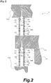
- the structure of the joint portion J1 will be described with reference to Fig. 2 .
- the outer circumference of the inner casing 132 is provided with an outward flange 132e.
- the outer casing 131 is provided with a pair of plate portions 131X, 131Y near its ceiling, which sandwiches the outward flange 132e.
- Heat insulation structures 500A and 500B are provided respectively between the outward flange 132e and one plate portion 131X (which will be referred to as the "first plate portion 131X” hereinafter) and between the outward flange 132e and the other plate portion 131Y (which will be referred to as the "second plate portion 131Y” hereinafter).
- Each heat insulation structure 500A includes a restriction member 510 having a substantially cylindrical shape, a plurality of heat insulation members 520 each having a cylindrical shape, and a plurality of slidable members 530 each having a cylindrical shape.
- the restriction member 510 is made of a resin material having high heat-insulating properties and has a cylindrical outer circumferential surface 511.
- the restriction member 510 is fixed to the first plate portion 131X of the outer casing 131 by a bolt 540.
- the inner circumference of the restriction member 510 has a stepped surface 512, which the head of the bolt 540 abuts.
- the lower end of the restriction member 520 only abuts the outward flange 132e of the inner casing 132 and is not fixed to it.
- the restriction member 510 in the heat insulation structure 500B is fixed to the outward flange 132e of the inner casing 132.
- the lower end of the restriction member 510 abuts the second plate portion 131Y of the outer casing 131 and is not fixed to it.
- the heat insulation member 520 is made of a brittle material having high heat-insulating properties and pressure resistance (e.g. a ceramic such as zirconia).
- the heat insulation member 520 is made of a material having heat conductivity lower than at least the material of the outer casing 131 and the inner casing 132.
- the heat insulation structure 500A includes four heat insulation members 520.
- a heat insulation structure in another embodiment may include at least two heat insulation members and the number thereof is not limited particularly.
- the slidable member 530 is made of a material having low emissivity and allowing the heat insulation member 520 to slide on it. Examples of such materials include a stainless steel and aluminum.
- the heat insulation structure 500A includes three slidable members 530.
- a heat insulation structure in another embodiment may include at least one slidable member and the number thereof is not limited particularly.
- the heat insulation members 520 and the slidable members 530 are arranged alternately along the direction of compression by the outer casing 131 and the inner casing 132 (more specifically, the first plate portion 131X and the outward flange 132e).
- the restriction member 510 is inserted through the heat insulation members 520 and the slidable members 530.
- a small gap is left between the outer circumferential surface 511 of the restriction member 510 and the inner circumferential surfaces of the heat insulation members 520 and between the outer circumferential surface 511 of the restriction member 510 and the inner circumferential surfaces of the slidable members 530.
- the heat insulation members 520 and the slidable members 530 are not adhered to anything.
- the heat insulation members 520 are constrained when the outer casing 131 and the inner casing 132 exert a compressive force on them but not constrained when a tensile force acts on them.
- the slidable members 530 are constrained when the outer casing 131 and the inner casing 132 exert a compressive force on them but not constrained when a tensile force acts on them.
- Each slidable member 530 is disposed between adjacent heat insulation members 520 and slidable on the heat insulation members 520.
- the heat insulation members 520 and the slidable members 530 are allowed to be displaced in directions perpendicular to the direction of compression by the outer casing 131 and the inner casing 132.
- the restriction member 510 restricts the amount of movement of the heat insulation members 520 and the slidable members 530 in the aforementioned perpendicular directions.
- the restriction member 510 made of a resin deforms to incline. Due to the presence of the slidable members 530 that are slidable between the heat insulation members 520, the four heat insulation members 520 in the heat insulation structure 500A are displaced rightward in Fig. 2 with the amount of displacement increasing from above to below. The four heat insulation members 520 in the heat insulation structure 500B are displaced rightward in Fig. 2 with the amount of displacement increasing from below to above.
- the joint portion J2 is provided in the portion by which the main shaft portion 121 and the supporting member 122 of the shaft member 120 are fixedly joined.
- first annular member 710 which includes a cylindrical portion 711 having a female screw provided on its inner circumference and an inward flange 712 provided at the lower end of the cylindrical portion 711.
- second annular member 720 which includes a cylindrical portion 721 having a female screw provided on its inner circumference and an outward flange 722 provided at the upper end of the cylindrical portion 721.
- the first annular member 710 and the second annular member 720 are made of a metal or the like.
- Heat insulation structures are provided on both the inner and outer circumferential surfaces of the second annular member 720.
- the heat insulation structure inside the second annular member 720 will be referred to as the first heat insulation structure 600A and the heat insulation structure outside the second annular member 720 will be referred to as the second heat insulation structure 600B.
- the first heat insulation structure 600A includes a restriction member 610A having a substantially cylindrical shape, a plurality of heat insulation members 620A each having a cylindrical shape, and a plurality of slidable members 630A each having a cylindrical shape.
- the restriction member 610A is made of a resin material having high heat-insulating properties and has a cylindrical inner circumferential surface. An outer circumferential surface of the restriction member 610A fits the inner circumferential surface of the second annular member 720.
- the heat insulation member 620A is made of a brittle material having high heat-insulating properties and pressure resistance (e.g. a ceramic such as zirconia).
- the heat insulation member 620A is made of a material having heat conductivity lower than at least the material of the main shaft portion 121 and the supporting member 122.
- the first heat insulation structure 600A includes three heat insulation members 620A.
- a first heat insulation structure in another embodiment may include at least two heat insulation members and the number thereof is not limited particularly.
- the slidable member 630A is made of a material having low emissivity and allowing the heat insulation member 620A to slide on it. Examples of such materials include a stainless steel and aluminum.
- the first heat insulation structure 600A includes two slidable members 630A.
- a first heat insulation structure in another embodiment may include at least one slidable member, and the number thereof is not limited particularly.
- the heat insulation members 620A and the slidable members 630A are arranged alternately along the direction of compression by the main shaft portion 121 and the supporting member 122 (more specifically, the lower end of the main shaft portion 121 and the upper end of the supporting member 122).
- the heat insulation members 620A and the slidable members 630A are arranged inside the restriction member 610A.
- a small gap is left between the inner circumferential surface of the restriction member 610A and the outer circumferential surfaces of the heat insulation members 620A and between the inner circumferential surface of the restriction member 610A and the outer circumferential surfaces of the slidable members 630A.
- the heat insulation members 620A and the slidable members 630A are not adhered to anything.
- the heat insulation members 620A are constrained when the main shaft portion 121 and the supporting member 122 exert a compressive force on them but not constrained when a tensile force acts on them.
- the slidable members 630A are constrained when the main shaft portion 121 and the supporting member 122 exert a compressive force on them but not constrained when a tensile force acts on them.
- Each slidable member 630A is disposed between adjacent heat insulation members 620A and slidable on the heat insulation members 620A.
- the heat insulation members 620A and the slidable members 630A are allowed to be displaced in directions perpendicular to the direction of compression by the main shaft portion 121 and the supporting member 122.
- the restriction member 610A restricts the amount of movement of the heat insulation members 620A and the slidable members 630A in the aforementioned perpendicular directions.
- the second heat insulation structure 600B also includes a restriction member 610B having a substantially cylindrical shape, a plurality of heat insulation members 620B each having a cylindrical shape, and a plurality of slidable members 630B each having a cylindrical shape.
- the restriction member 610B is made of a resin material having high heat-insulating properties and has a cylindrical inner circumferential surface. An outer circumferential surface of the restriction member 610B fits the inner circumferential surface of the first annular member 710.
- the heat insulation member 620B is made of a brittle material having high heat-insulating properties and pressure resistance (e.g. a ceramic such as zirconia).
- the heat insulation member 620B is made of a material having heat conductivity lower than at least the material of the main shaft portion 121 and the supporting member 122.
- the second heat insulation structure 600B includes three heat insulation members 620B.
- a second heat insulation structure in another embodiment may include at least two heat insulation members and the number thereof is not limited particularly.
- the slidable member 630B is made of a material having low emissivity and allowing the heat insulation member 620B to slide on it. Examples of such materials include a stainless steel and aluminum.
- the second heat insulation structure 600B includes two slidable members 630B.
- a second heat insulation structure in another embodiment may include at least one slidable member and the number thereof is not limited particularly.
- the heat insulation members 620B and the slidable members 630B are arranged alternately along the direction of compression by the main shaft portion 121 and the supporting member 122 (more specifically, the inward flange 712 of the first annular member 710 fixedly attached to the main shaft portion 121 and the outward flange 722 of the second annular member 720 fixedly attached the supporting member 122).
- the heat insulation members 620B and the slidable members 630B are arranged inside the restriction member 610B.
- a small gap is left between the inner circumferential surface of the restriction member 610B and the outer circumferential surfaces of the heat insulation members 620B and between the inner circumferential surface of the restriction member 610B and the outer circumferential surfaces of the slidable members 630B.
- the heat insulation members 620B and the slidable members 630B are not adhered to anything.
- the heat insulation members 620B are constrained when the main shaft portion 121 and the supporting member 122 exert a tensile force on them but not constrained when a compressive force acts on them.
- the slidable members 630B are constrained when the main shaft portion 121 and the supporting member 122 exert a tensile force on them but not constrained when a compressive force acts on them.
- Each slidable member 630B is disposed between adjacent heat insulation members 620B and slidable on the heat insulation members 620B.
- the heat insulation members 620B and the slidable members 630B are allowed to be displaced in directions perpendicular to the direction of compression by the main shaft portion 121 and the supporting member 122.
- the restriction member 610B restricts the amount of movement of the heat insulation members 620B and the slidable members 630B in the aforementioned perpendicular directions.
- each heat insulation member 620A, 620B only slides between the slidable members 630A, 630B, thus the shearing stress acting on each heat insulation member 620A, 620B is small.
- the lower portions of the shaft may be at an angle with respect to the upper portions of the shaft due to vibrations produced by driving or other reasons.
- each heat insulation member 620A, 620B only slides between the slidable members 630A, 630B, thus the shearing stress acting on each heat insulation member 620A, 620B is small.
- the heat insulation members 520, 620A, 620B made of a material having heat conductivity lower than the two components for which heat insulation is to be provided are constrained when the two components exert a compressive force on them but not constrained when a tensile force acts on them. Therefore, a tensile force does not act on the heat insulation members 520, 620A, and 620B. Moreover, the heat insulation members 520, 620A, and 620B are allowed to be displaced in directions perpendicular to the direction of compression by the two components.
- the heat insulation structure can prevent the heat insulation members 520, 620A, and 620B from being broken while providing satisfactory heat insulation.
- the flange 513 of the heat insulation structure 500B provided at the lower end (in the drawing) of the restriction member 510 is subject to a compressive force by the heat insulation member 520 and the plate portion 131Y of the outer casing 131.
- the flange 513 provided on the restriction member 510 enables the members constituting the heat insulation structure (i.e. the restriction member 510, the heat insulation members 520, and the slidable members 530) to be handled as one integral component.
- the members constituting the heat insulation structure i.e. the restriction member 510, the heat insulation members 520, and the slidable members 530
- the members constituting the heat insulation structure can be handled as one integral component.
- the restriction member 510 is made of a resin material, it may plastically deform when a high compressive force acts on it. In the following, a structure that is designed to prevent a great compressive force from acting on the restriction member 510 will be described.
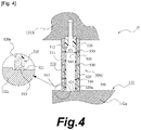
- Fig. 4 is a schematic cross sectional view illustrating a first modification of the heat insulation structure in the joint portion of the outer casing and the inner casing of the embodiment.
- Fig. 4 also includes an enlarged view of the encircled portion.
- the structure is basically the same as the above-described structure illustrated in Fig. 2 and the same components are denoted by the same reference signs for the sake of convenience to eliminate the need for further description.
- Fig. 4 illustrates a heat insulation structure 500C provided between the plate portion 131X of the outer casing 131 and the outward flange 132e of the inner casing 132.
- a like heat insulation structure may also be employed between the outward flange 132e of the inner casing 132 and the plate portion 131Y of the outer casing 131.
- the heat insulation structure 500C also includes a restriction member 510 having a substantially cylindrical shape, a plurality of heat insulation members 520 each having a cylindrical shape, and a plurality of slidable members 530 each having a cylindrical shape, as with the structure of the embodiment described above. Details of the restriction member 510 are the same as the above-described embodiment and will not be described further.
- the restriction member 510 is fixedly attached to the first plate portion 131X of the outer casing 131 by a bolt 540. As in the above-described embodiment, the lower end of the restriction member 510 only abuts the outward flange 132e of the inner casing 132 and is not fixed to it.
- the heat insulation member 520 and the slidable member 530 are also basically the same as those in the above-described embodiment.
- the heat insulation member 520a that is in contact with the outward flange 132e of the inner casing 132 has an annular recess 521 provided on its inner circumference on the side in contact with the outward flange 132e.
- the annular recess 521 engages with a flange 513 or projecting portion provided on the restriction member 510.
- the inner casing 132 is the component to which the restriction member 520 is not fixed, among the outer and inner casings 131, 132.
- the heat insulation structure 500C structured as above also provides advantageous effects the same as the heat insulation structures 500A, 500B of the embodiment described above.
- the flange 513 of the restriction member 510 is situated in the annular recess 521. This can prevent a compressive force from acting on the outward flange 513 or reduce the compressive force. Therefore, the restriction member 510 can be prevented from plastically deforming or breaking.
- the flange 513 provided on the restriction member 510 is configured to engage with the annular recess 521 provided on the heat insulation member 520a.
- at least one projection may be provided on the restriction member 510 and at least one annular or not-annular recess may be provided on the heat insulation member 520a so that they can engage with each other.
- Fig. 5 is a schematic cross sectional view illustrating a second modification of the heat insulation structure in the joint portion of the outer casing and the inner casing of the embodiment.
- Fig. 5 also includes an enlarged view of the encircled portion.
- the structure is basically the same as the above-described structure illustrated in Fig. 2 and the same components are denoted by the same reference signs for the sake of convenience to eliminate the need for further description.
- Fig. 5 illustrates a heat insulation structure 500D provided between the plate portion 131X of the outer casing 131 and the outward flange 132e of the inner casing 132.
- a like heat insulation structure may also be employed between the outward flange 132e of the inner casing 132 and the plate portion 131Y of the outer casing 131.
- the heat insulation structure 500D also includes a restriction member 510 having a substantially cylindrical shape, a plurality of heat insulation members 520 each having a cylindrical shape, and a plurality of slidable members 530 each having a cylindrical shape, as with the structure of the embodiment described above. Details of the restriction member 510 are the same as the above-descried embodiment and will not be described further.
- the restriction member 510 is fixedly attached to the first plate portion 131X of the outer casing 131 by a bolt 540. As in the above-described embodiment, the lower end of the restriction member 510 only abuts the outward flange 132e of the inner casing 132 and is not fixed to it.
- the heat insulation member 520 and the slidable member 530 are also basically the same as those in the above-described embodiment. What is different in this modification is that an annular elastic member 550 having strength higher than the restriction member 510 is provided between and in contact with the outward flange 132e of the inner casing 132 and the heat insulation member 520.
- the elastic member 550 is made of a metal such as a stainless steel.
- the inner casing 132 is the component to which the restriction member 520 is not fixed, among the outer and inner casings 131, 132.
- the elastic member 550 has an annular recess 550a provided on its inner circumference on the side in contact with the outward flange 132e.
- the annular recess 550a engages with a flange 513 or projecting portion provided on the restriction member 510.
- the heat insulation structure 500D structured as above also provides advantageous effects the same as the heat insulation structures 500A, 500B of the embodiment described above.
- the flange 513 of the restriction member 510 is situated in the annular recess 550a. This can prevent a compressive force from acting on the flange 513 or reduce the compressive force. Therefore, the restriction member 510 can be prevented from plastically deforming or breaking.
- the flange 513 provided on the restriction member 510 is configured to engage with the annular recess 550a provided on the elastic member 550.
- at least one projection may be provided on the restriction member 510 and at least one annular or not-annular recess may be provided on the elastic member 550 so that they can engage with each other.
- the restriction member 510 is fixed by the bolt 540.
- a locking washer or a locking set screw may be used to prevent loosening of the restriction member 510.
- the restriction member 510 may be fixed without using a securing member such as a bolt as with the restriction members 610A, 610B in the joint portion J2.
- the restriction member 510 may be fixed by fitting into another member with a small clearance between them or pinned.
- a structure similar to the structures of the first and second modifications may be used in the joint portion J2 also. In that case, the projecting portion provided on the restriction member is configured to project radially inwardly. A recess with which the projecting portion engages is provided on the outer circumference of the heat insulation member or the elastic member.
Landscapes
- Engineering & Computer Science (AREA)
- General Engineering & Computer Science (AREA)
- Mechanical Engineering (AREA)
- Physics & Mathematics (AREA)
- Thermal Sciences (AREA)
- Thermal Insulation (AREA)
- Reciprocating Pumps (AREA)
- Filling Or Discharging Of Gas Storage Vessels (AREA)
- Heat-Exchange Devices With Radiators And Conduit Assemblies (AREA)
Abstract
Description
- The present invention relates to a heat insulation structure provided in a joint portion between two components that are fixed to each other and a liquid supply system including such a heat insulation structure.
- It is known in prior art to use a liquid supply system having a pump chamber using a bellows to cause a cryogenic liquid such as liquid nitrogen or liquid helium to circulate in a circulation fluid passage. It is necessary for such a liquid supply system to keep the interior of the system in a ultra-low temperature state. Hence, if the system includes two structural components fixed to each other one of which is exposed to the outside air and apt to transfer heat to the interior of the system, it is necessary to provide a heat insulation structure in the joint portion of these two components.
- Moreover, in the case of a large-size liquid supply system, it is necessary that structural components of the system have high strength. To enhance the strength, it is desirable that the structural components be made of a metal material, such as a stainless steel or a copper alloy. However, such metal materials have high heat conductivities and are not suitable for use as materials of the components of a heat insulation structure. There are high strength, low heat-conductive ceramic materials, such as zirconia. However, while such ceramic materials have high resistance against compressive load, their tensile strength is low. Moreover, such ceramic materials are apt to be broken when a shearing force acts on them.
-
- [PTL 1]
Japanese Patent Application Laid-Open No.2007-177667 - [PTL 2]
Japanese Patent Application Laid-Open No.2009-2252 - An object of the present invention is to provide a heat insulation structure and a liquid supply system that can prevent breakage of a heat insulation member while providing satisfactory heat insulation.
- To achieve the above object, the following features are adopted.
- An aspect of the present invention is a heat insulation structure provided in a joint portion between two components fixed to each other and subject to a compressive force, comprising;
heat insulation members disposed between the two components and made of a material having heat conductivity lower than the two component; and
a slidable member slidable on the heat insulation members,
wherein at least two of the heat insulation members are arranged along the direction of compression and at least one of the slidable member is disposed between the heat insulation members which are adjacent to each other, the heat insulation members and the slidable member being allowed to be displaced in directions perpendicular to the direction of compression. - The heat insulation members are allowed to be displaced in directions perpendicular to the direction of compression by the two components, thus the heat insulation members are merely caused to slide on the slidable member even when a force acts in the perpendicular directions. Therefore, a force in a shearing direction scarcely acts on the heat insulation members. In consequence, the heat insulation members are prevented from breaking.
- The heat insulation structure may include a restriction member made of a resin that restricts the amount of movement of the heat insulation members and the slidable member in the perpendicular directions.
- This prevents the heat insulation members and the slidable member from being displaced greatly.
- The restriction member may be fixed on one of the two components, and the insulation member that is in contact with the other component among the two components on which the restriction member is not fixed may have a recessed portion provided on its end on the side facing the other component on which the restriction member is not fixed, the recessed portion engaging with a projecting portion provided on the restriction member.
- This feature prevents a compressive force by the two components from being exerted on the restriction member, or the compressive force exerted on the restriction member can be reduced.
- The restriction member may be fixed on one of the two components, an elastic member having strength higher than the restriction member may be disposed between the other component among the two components on which the restriction member is not fixed and the heat insulation member, and the elastic member may have a recessed portion provided on its end on the side facing the other component on which the restriction member is not fixed, the recessed portion engaging with a projecting portion provided on the restriction member.
- This feature prevents a compressive force by the two components from being exerted on the restriction member, or the compressive force exerted on the restriction member can be reduced.
- A first component among the two components may be disposed on both sides of a second component among the two components with respect to the direction of compression, and the heat insulation structure may be provided between the first component and the second component on each side of the second component with respect to the direction of compression.
- Thus, the heat insulation members are constrained when the two components exert a compressive force on them but not constrained when a tensile force acts on them. Therefore, a tensile force does not act on the heat insulation members.
- Another aspect of the present invention is a liquid supply system comprises:
- a container provided with a pump chamber inside it;
- a shaft member that moves vertically upward and downward in the container; and
- a bellows provided coaxially with the shaft member that expands and contracts with upward and downward motion of the shaft member,
- wherein the shaft member includes a main shaft portion and a supporting member that supports the bellows, and the above-described heat insulation structure is provided between the main shaft portion and the supporting member.
- The heat insulation structure according to the present invention can prevent breakage of a heat insulation member while providing satisfactory heat insulation.
-
- [
Fig. 1 ]
Fig. 1 is a schematic diagram illustrating a liquid supply system in an embodiment. - [
Fig. 2 ]
Fig. 2 is a schematic cross sectional view of an insulation structure provided in a joint portion between an outer casing and an inner casing in the embodiment. - [
Fig. 3 ]
Fig. 3 is a schematic cross sectional view of an insulation structure provided in a joint portion between a main shaft portion and a supporting member in the embodiment. - [
Fig. 4 ]
Fig. 4 is a schematic cross sectional view of a first modification of the insulation structure provided in the joint portion between the outer casing and the inner casing in the embodiment. - [
Fig. 5 ]
Fig. 5 is a schematic cross sectional view of a second modification of the insulation structure provided in the joint portion between the outer casing and the inner casing in the embodiment. - In the following, a mode for carrying out the present invention will be described specifically by way of example on the basis of an embodiment with reference to the drawings. The dimensions, materials, shapes, relative arrangements, and other features of the components that will be described in connection with the embodiments are not intended to limit the technical scope of the present invention only to them, unless particularly stated.
- A liquid supply system in an embodiment will be described with reference to
Figs. 1 to 3 . The liquid supply system is suitably used for the purpose of, for example, maintaining a superconducting device in a ultra-low temperature state. Superconducting devices require perpetual cooling of components such as superconducting coils. Thus, a cooled device including a superconducting coil and other components is perpetually cooled by continuous supply of a cryogenic liquid (such as liquid nitrogen or liquid helium) to the cooled device. Specifically, a circulating fluid passage passing through the cooled device is provided, and the liquid supply system is connected to the circulating fluid passage to cause the cryogenic liquid to circulate, thereby enabling perpetual cooling of the cooled device. -
Fig. 1 is a schematic diagram illustrating the overall configuration of the liquid supply system, where the overall configuration of the liquid supply system is illustrated in a cross section.Fig. 1 illustrates the overall configuration in a cross section in a plane containing the center axis. - The
liquid supply system 10 includes a main unit of the liquid supply system 100 (which will be referred to as the "main system unit 100" hereinafter), avacuum container 200 in which themain system unit 100 is housed, and pipes (including aninlet pipe 310 and an outlet pipe 320). Themain system unit 100 and thevacuum container 200 are fixed to each other. - The
inlet pipe 310 and theoutlet pipe 320 both extend into the interior of thevacuum container 200 from outside thevacuum container 200 and are connected to themain system unit 100. The interior of thevacuum container 200 is a hermetically sealed space. The interior space of thevacuum container 200 outside themain system unit 100, theinlet pipe 310, and theoutlet pipe 320 is kept in a vacuum state. Thus, this space provides heat insulation. Theliquid supply system 10 is normally installed on a horizontal surface. In the installed state, the upward direction of theliquid supply system 10 inFig. 1 is the vertically upward direction and the downward direction inFig. 1 is the vertically downward direction. - The
main system unit 100 includes alinear actuator 110 serving as a driving source, ashaft member 120 that is moved in vertically upward and downward directions by thelinear actuator 110, and acontainer 130. Thelinear actuator 110 is fixed on something suitable, which may be thecontainer 130 or something that is not shown in the drawings. In this embodiment, thelinear actuator 110 is fixed on thecontainer 130 by anactuator supporter 111. Thecontainer 130 includes anouter casing 131 and aninner casing 132 provided inside theouter casing 131. Theouter casing 131 and theinner casing 132 are connected by a joint portion J1. Theshaft member 120 extends from outside thecontainer 130 into the inside through anopening 131a provided in the ceiling portion of theouter casing 131. Theouter casing 131 has aninlet 131b and anoutlet 131c for liquid (cryogenic liquid) in its bottom portion. Theaforementioned inlet pipe 310 is connected to theinlet 131b and theoutlet pipe 320 is connected to theoutlet 131c. - Inside the
outer casing 131 are provided a plurality of structural components besides theinner casing 132. These structural components and theinner casing 132 compart the interior space into plurality of spaces, which constitute a plurality of pump chambers and passages for liquid. In the following, the structure inside theouter casing 131 will be described in further detail. - The
shaft member 120 has amain shaft portion 121 and a supportingmember 122 on which a plurality of bellows (including a first bellows 141, a second bellows 142, and a fourth bellows 152) are supported. Themain shaft portion 121 and the supportingmember 122 are connected by a joint portion J2. The supportingmember 122 includes acenter shaft portion 122a, acylindrical portion 122b that surrounds the outer circumference of thecenter shaft portion 122a, and a connectingportion 122c that connects thecenter shaft portion 122a and thecylindrical portion 122b. Thecylindrical portion 122b is provided with an upper outward flange 122b1 at its upper end and a lower outward flange 122b2 at its lower end. - The
inner casing 132 has abody portion 132a having a substantially cylindrical shape, a first inward flange 132b1 provided near the center of thebody portion 132a, and abottom plate 132c. Theinner casing 132 is integral with theouter casing 131, and thus theinner casing 132 is kept stationary relative to theouter casing 131 even while theshaft member 120 moves upward and downward. - Inside the
body portion 132a of theinner casing 132, there are a plurality of first fluid passages 132a1 that extend in the axial direction below the first inward flange 132b1 and are spaced apart from one another along the circumferential direction. Inside thebody portion 132a, there also is a second fluid passage 132a2, which is an axially extending cylindrical space provided radially outside the region in which the first fluid passages 132a1 are provided. The bottom portion of theinner casing 132 is provided with afluid passage 132d that extends circumferentially and radially outwardly to join to the first fluid passages 132a1. Furthermore, thebottom plate 132c of theinner casing 132 is provided with a fluid passage 132c1 that extends circumferentially and radially outwardly. Thesefluid passages 132d and 132c1 extend uniformly along the circumferential direction to allow liquid to flow radially outwardly in all directions, namely 360 degrees about the center axis. - Inside the
container 130, there are provided thefirst bellows 141 and the second bellows 142, which expand and contract with the up and down motion of theshaft member 120. The first bellows 141 and the second bellows 142 are arranged one above the other along the vertical direction. The upper end of the first bellows 141 is fixedly attached to the upper outward flange 122b1 of thecylindrical portion 122b of the supportingmember 122 and the lower end of the first bellows 141 is fixedly attached to the first inward flange 132b1 of theinner casing 132. The upper end of the second bellows 142 is fixedly attached to the first inward flange 132b1 of theinner casing 132 and the lower end of the second bellows 142 is fixedly attached to the lower outward flange 122b2 of thecylindrical portion 122b of the supportingmember 122. The space surrounding the outer circumference of thefirst bellows 141 forms a first pump chamber P1 and the space surrounding the outer circumference of the second bellows 142 forms a second pump chamber P2. - Inside the
container 130, there also are provided a third bellows 151 and the fourth bellows 152, which expand and contract with the up and down motion of theshaft member 120. The upper end of the third bellows 151 is fixedly attached to themain shaft portion 121 of theshaft member 120 and the lower end of the third bellows 151 is fixedly attached to the ceiling portion of theouter casing 131. Thus, theopening 131a of theouter casing 131 is closed. The upper end of the fourth bellows 152 is fixedly attached to a second inward flange 132b2 provided on theinner casing 132 and the lower end of the fourth bellows 152 is fixedly attached to the connectingportion 122c of the supportingmember 122. Thus, the space around thecenter shaft portion 122a of the supportingmember 122 and the fluid passage passing through the first pump chamber P1 is separated. - There are four check valves 160 including a
first check valve 160A, asecond check valve 160B, athird check valve 160C, and afourth check valve 160D, which are provided at different locations inside thecontainer 130. Each of these check valves 160 is an annular component provided coaxially with theshaft member 120. Each of the check valves 160 is configured to allow flow of liquid in radial directions from inside to outside and to block flow of liquid in radial directions from outside to inside. - The
first check valve 160A and thethird check valve 160C are provided in the fluid passage passing through the first pump chamber P1. Thefirst check valve 160A and thethird check valve 160C function to block backflow of liquid pumped by the pumping effect of the first pump chamber P1. Specifically, thefirst check valve 160A is provided on the upstream side of the first pump chamber P1 and thethird check valve 160C is provided on the downstream side of the first pump chamber P1. More specifically, thefirst check valve 160A is provided in thefluid passage 132d provided in the bottom portion of theinner casing 132. Thethird check valve 160C is provided in the fluid passage formed in the vicinity of the second inward flange 132b2 provided on theinner casing 132. - The
second check valve 160B and thefourth check valve 160D are provided in the fluid passage passing through the second pump chamber P2. Thesecond check valve 160B and thefourth check valve 160D function to block backflow of liquid pumped by the pumping effect of the second pump chamber P2. Specifically, thesecond check valve 160B is provided on the upstream side of the second pump chamber P2 and thefourth check valve 160D is provided on the downstream side of the second pump chamber P2. More specifically, thesecond check valve 160B is provided in the fluid passage 132c1 provided in thebottom plate 132c of theinner casing 132. Thefourth check valve 160D is provided in the fluid passage formed in the vicinity of the first inward flange 132b1 of theinner casing 132. - The overall operation of the liquid supply system will be described. When the
shaft member 120 is lowered by thelinear actuator 110, thefirst bellows 141 contracts and the second bellows 142 expands. Consequently, the fluid pressure in the first pump chamber P1 decreases. Then, thefirst check valve 160A is opened and thethird check valve 160C is closed. In consequence, liquid supplied from outside theliquid supply system 10 through the inlet pipe 310 (indicated by arrow S10) is taken into the interior of thecontainer 130 through theinlet 131b and passes through thefirst check valve 160A (indicated by arrow S11). Then, the liquid having passed through thefirst check valve 160A is pumped into the first pump chamber P1 through the first fluid passage 132a1 in thebody portion 132a of theinner casing 132. On the other hand, the fluid pressure in the second pump chamber P2 increases. Then, thesecond check valve 160B is closed and thefourth check valve 160D is opened. In consequence, the liquid in the second pump chamber P2 is pumped into the second fluid passage 132a2 provided in thebody portion 132a through thefourth check valve 160D (indicated by arrow T12). Then, the fluid passes through theoutlet 131c and is brought to the outside of theliquid supply system 10 through the outlet pipe 320 (indicated by arrow T10). - When the
shaft member 120 is raised by thelinear actuator 110, the first bellows 141 expands and the second bellows 142 contracts. Consequently, the fluid pressure in the first pump chamber P1 increases. Then, thefirst check valve 160A is closed and thethird check valve 160C is opened. In consequence, the liquid in the first pump chamber P1 is pumped into the second fluid passage 132a2 provided in thebody portion 132a through thethird check valve 160C (indicated by arrow T11). Then, the liquid passes through theoutlet 131c and is brought to the outside of theliquid supply system 10 through the outlet pipe 320 (indicated by arrow T10). On the other hand, the fluid pressure in the second pump chamber P2 decreases. Then, thesecond check valve 160B is opened and thefourth check valve 160D is closed. In consequence, liquid supplied from outside theliquid supply system 10 through the inlet pipe 310 (indicated by arrow S10) is taken into the interior of thecontainer 130 through theinlet 131b and passes through thesecond check valve 160B (indicated by arrow S12). Then, the liquid having passed through thesecond check valve 160B is pumped into the second pump chamber P2. - As above, the
liquid supply system 10 can cause liquid to flow from theinlet pipe 310 to theoutlet pipe 320 both when theshaft member 120 moves downward and when theshaft member 120 moves upward. Hence, the phenomenon called pulsation can be reduced. - It is necessary that the interior of the
main system unit 100 of theliquid supply system 10 having the above structure be kept in a ultra-low temperature state. In the case of theliquid supply system 10, heat is apt to be transferred through a path from theouter casing 131 to aninner casing 132 and a path from the atmosphere side of theshaft member 120 to the interior of thecontainer 130. To avoid such heat transfer, theliquid supply system 10 is provided with a heat insulation structure in the joint portion J1 between theouter casing 131 and theinner casing 132 and a heat insulation structure in the joint portion J2 between themain shaft portion 121 and the supportingmember 122 of theshaft member 120. In the following, these heat insulation structures will be described. - The
outer casing 131 and theinner casing 132 are respectively fixed by a fixing structure (not illustrated) provided in a portion that does not need to have a heat insulation structure. The joint portion J1 of theouter casing 131 and theinner casing 132 is subject to a compressive force by theouter casing 131 and theinner casing 132 The joint portion J1 is configured to provide a support against the compressive force. As described above, the joint portion J1 has the function of heat insulation to prevent outside heat from being transferred to the interior of themain system unit 100. In the following, the structure of the joint portion J1 will be described with reference toFig. 2 . - The outer circumference of the
inner casing 132 is provided with anoutward flange 132e. Theouter casing 131 is provided with a pair ofplate portions outward flange 132e.Heat insulation structures outward flange 132e and oneplate portion 131X (which will be referred to as the "first plate portion 131X" hereinafter) and between theoutward flange 132e and theother plate portion 131Y (which will be referred to as the "second plate portion 131Y" hereinafter). There are a plurality ofheat insulation structures 500A and a plurality ofheat insulation structures 500B which are spaced from one another along the circumferential direction about the center axis of theshaft member 120. Though not shown in the drawings, a sealing member that seals the gap between theouter casing 131 and theinner casing 132 is provided. - The
heat insulation structures heat insulation structure 500A will be described. Eachheat insulation structure 500A includes arestriction member 510 having a substantially cylindrical shape, a plurality ofheat insulation members 520 each having a cylindrical shape, and a plurality ofslidable members 530 each having a cylindrical shape. Therestriction member 510 is made of a resin material having high heat-insulating properties and has a cylindrical outercircumferential surface 511. Therestriction member 510 is fixed to thefirst plate portion 131X of theouter casing 131 by abolt 540. The inner circumference of therestriction member 510 has a steppedsurface 512, which the head of thebolt 540 abuts. The lower end of therestriction member 520 only abuts theoutward flange 132e of theinner casing 132 and is not fixed to it. Therestriction member 510 in theheat insulation structure 500B is fixed to theoutward flange 132e of theinner casing 132. The lower end of therestriction member 510 abuts thesecond plate portion 131Y of theouter casing 131 and is not fixed to it. - The
heat insulation member 520 is made of a brittle material having high heat-insulating properties and pressure resistance (e.g. a ceramic such as zirconia). Theheat insulation member 520 is made of a material having heat conductivity lower than at least the material of theouter casing 131 and theinner casing 132. Theheat insulation structure 500A includes fourheat insulation members 520. A heat insulation structure in another embodiment may include at least two heat insulation members and the number thereof is not limited particularly. Theslidable member 530 is made of a material having low emissivity and allowing theheat insulation member 520 to slide on it. Examples of such materials include a stainless steel and aluminum. Theheat insulation structure 500A includes threeslidable members 530. A heat insulation structure in another embodiment may include at least one slidable member and the number thereof is not limited particularly. - The
heat insulation members 520 and theslidable members 530 are arranged alternately along the direction of compression by theouter casing 131 and the inner casing 132 (more specifically, thefirst plate portion 131X and theoutward flange 132e). Therestriction member 510 is inserted through theheat insulation members 520 and theslidable members 530. A small gap is left between the outercircumferential surface 511 of therestriction member 510 and the inner circumferential surfaces of theheat insulation members 520 and between the outercircumferential surface 511 of therestriction member 510 and the inner circumferential surfaces of theslidable members 530. Theheat insulation members 520 and theslidable members 530 are not adhered to anything. - Arranged as above, the
heat insulation members 520 are constrained when theouter casing 131 and theinner casing 132 exert a compressive force on them but not constrained when a tensile force acts on them. Theslidable members 530 are constrained when theouter casing 131 and theinner casing 132 exert a compressive force on them but not constrained when a tensile force acts on them. Eachslidable member 530 is disposed between adjacentheat insulation members 520 and slidable on theheat insulation members 520. Theheat insulation members 520 and theslidable members 530 are allowed to be displaced in directions perpendicular to the direction of compression by theouter casing 131 and theinner casing 132. As described above, therestriction member 510 restricts the amount of movement of theheat insulation members 520 and theslidable members 530 in the aforementioned perpendicular directions. - As described above, while a compressive force acts on the
heat insulation members 520, a tensile force does not act on them. When cryogenic liquid circulates in the interior of themain system unit 100, the temperature difference between theouter casing 131 and theinner casing 132 becomes large, and then theinner casing 132 contracts relative to theouter casing 131. Consequently, theoutward flange 132e moves rightward inFig. 2 relative to theouter casing 131. In consequence, the lower portion of theheat insulation structure 500A is pulled toward the right side inFig. 2 and the upper portion of theheat insulation structure 500B is pulled toward the right side inFig. 2 . Thus, a force that inclines theheat insulation structures restriction member 510 made of a resin deforms to incline. Due to the presence of theslidable members 530 that are slidable between theheat insulation members 520, the fourheat insulation members 520 in theheat insulation structure 500A are displaced rightward inFig. 2 with the amount of displacement increasing from above to below. The fourheat insulation members 520 in theheat insulation structure 500B are displaced rightward inFig. 2 with the amount of displacement increasing from below to above. - The joint portion J2 is provided in the portion by which the
main shaft portion 121 and the supportingmember 122 of theshaft member 120 are fixedly joined. In the following, we will describe the structure of fixedly joining themain shaft portion 121 and the supportingmember 122 and the structure of the joint portion J2 having the function of heat insulation with reference toFig. 3 . - To the
main shaft portion 121 is fixedly attached by screwing a firstannular member 710, which includes acylindrical portion 711 having a female screw provided on its inner circumference and aninward flange 712 provided at the lower end of thecylindrical portion 711. To the supportingmember 122 is fixedly attached by screwing a secondannular member 720, which includes acylindrical portion 721 having a female screw provided on its inner circumference and anoutward flange 722 provided at the upper end of thecylindrical portion 721. The firstannular member 710 and the secondannular member 720 are made of a metal or the like. Heat insulation structures are provided on both the inner and outer circumferential surfaces of the secondannular member 720. For the sake of convenience of description, the heat insulation structure inside the secondannular member 720 will be referred to as the firstheat insulation structure 600A and the heat insulation structure outside the secondannular member 720 will be referred to as the secondheat insulation structure 600B. - The first
heat insulation structure 600A includes arestriction member 610A having a substantially cylindrical shape, a plurality ofheat insulation members 620A each having a cylindrical shape, and a plurality ofslidable members 630A each having a cylindrical shape. Therestriction member 610A is made of a resin material having high heat-insulating properties and has a cylindrical inner circumferential surface. An outer circumferential surface of therestriction member 610A fits the inner circumferential surface of the secondannular member 720. - The
heat insulation member 620A is made of a brittle material having high heat-insulating properties and pressure resistance (e.g. a ceramic such as zirconia). Theheat insulation member 620A is made of a material having heat conductivity lower than at least the material of themain shaft portion 121 and the supportingmember 122. The firstheat insulation structure 600A includes threeheat insulation members 620A. A first heat insulation structure in another embodiment may include at least two heat insulation members and the number thereof is not limited particularly. Theslidable member 630A is made of a material having low emissivity and allowing theheat insulation member 620A to slide on it. Examples of such materials include a stainless steel and aluminum. The firstheat insulation structure 600A includes twoslidable members 630A. A first heat insulation structure in another embodiment may include at least one slidable member, and the number thereof is not limited particularly. - The
heat insulation members 620A and theslidable members 630A are arranged alternately along the direction of compression by themain shaft portion 121 and the supporting member 122 (more specifically, the lower end of themain shaft portion 121 and the upper end of the supporting member 122). Theheat insulation members 620A and theslidable members 630A are arranged inside therestriction member 610A. A small gap is left between the inner circumferential surface of therestriction member 610A and the outer circumferential surfaces of theheat insulation members 620A and between the inner circumferential surface of therestriction member 610A and the outer circumferential surfaces of theslidable members 630A. Theheat insulation members 620A and theslidable members 630A are not adhered to anything. - Arranged as above, the
heat insulation members 620A are constrained when themain shaft portion 121 and the supportingmember 122 exert a compressive force on them but not constrained when a tensile force acts on them. Theslidable members 630A are constrained when themain shaft portion 121 and the supportingmember 122 exert a compressive force on them but not constrained when a tensile force acts on them. Eachslidable member 630A is disposed between adjacentheat insulation members 620A and slidable on theheat insulation members 620A. Theheat insulation members 620A and theslidable members 630A are allowed to be displaced in directions perpendicular to the direction of compression by themain shaft portion 121 and the supportingmember 122. As described above, therestriction member 610A restricts the amount of movement of theheat insulation members 620A and theslidable members 630A in the aforementioned perpendicular directions. - The second
heat insulation structure 600B also includes arestriction member 610B having a substantially cylindrical shape, a plurality ofheat insulation members 620B each having a cylindrical shape, and a plurality ofslidable members 630B each having a cylindrical shape. Therestriction member 610B is made of a resin material having high heat-insulating properties and has a cylindrical inner circumferential surface. An outer circumferential surface of therestriction member 610B fits the inner circumferential surface of the firstannular member 710. - The
heat insulation member 620B is made of a brittle material having high heat-insulating properties and pressure resistance (e.g. a ceramic such as zirconia). Theheat insulation member 620B is made of a material having heat conductivity lower than at least the material of themain shaft portion 121 and the supportingmember 122. The secondheat insulation structure 600B includes threeheat insulation members 620B. A second heat insulation structure in another embodiment may include at least two heat insulation members and the number thereof is not limited particularly. Theslidable member 630B is made of a material having low emissivity and allowing theheat insulation member 620B to slide on it. Examples of such materials include a stainless steel and aluminum. The secondheat insulation structure 600B includes twoslidable members 630B. A second heat insulation structure in another embodiment may include at least one slidable member and the number thereof is not limited particularly. - The
heat insulation members 620B and theslidable members 630B are arranged alternately along the direction of compression by themain shaft portion 121 and the supporting member 122 (more specifically, theinward flange 712 of the firstannular member 710 fixedly attached to themain shaft portion 121 and theoutward flange 722 of the secondannular member 720 fixedly attached the supporting member 122). Theheat insulation members 620B and theslidable members 630B are arranged inside therestriction member 610B. A small gap is left between the inner circumferential surface of therestriction member 610B and the outer circumferential surfaces of theheat insulation members 620B and between the inner circumferential surface of therestriction member 610B and the outer circumferential surfaces of theslidable members 630B. Theheat insulation members 620B and theslidable members 630B are not adhered to anything. - Arranged as above, the
heat insulation members 620B are constrained when themain shaft portion 121 and the supportingmember 122 exert a tensile force on them but not constrained when a compressive force acts on them. Theslidable members 630B are constrained when themain shaft portion 121 and the supportingmember 122 exert a tensile force on them but not constrained when a compressive force acts on them. Eachslidable member 630B is disposed between adjacentheat insulation members 620B and slidable on theheat insulation members 620B. Theheat insulation members 620B and theslidable members 630B are allowed to be displaced in directions perpendicular to the direction of compression by themain shaft portion 121 and the supportingmember 122. As described above, therestriction member 610B restricts the amount of movement of theheat insulation members 620B and theslidable members 630B in the aforementioned perpendicular directions. - With the above structure, while a compressive force acts on the
heat insulation members main system unit 100, the temperature difference between themain shaft portion 121 and the supportingmember 122 becomes large, and then the supportingmember 122 contracts relatively to decrease in diameter. The firstannular member 710 and the secondannular member 720 also contract with their diameters decreasing from above to below. Accordingly, therestriction members heat insulation members heat insulation member slidable members heat insulation member heat insulation member slidable members heat insulation member - In the heat insulation structure, the
heat insulation members heat insulation members heat insulation members heat insulation members slidable members heat insulation members heat insulation members heat insulation members - In the above-described heat insulation structure provided in the joint portion J1, when a compressive force acts between the pair of
plate portions outer casing 131 and theoutward flange 132e of theinner casing 132, a compressive force acts on therestriction member 510. Specifically, theflange 513 of theheat insulation structure 500A provided at the lower end (in the drawing) of therestriction member 510 is subject to a compressive force by theheat insulation member 520 and theoutward flange 132e of theinner casing 132. Theflange 513 of theheat insulation structure 500B provided at the lower end (in the drawing) of therestriction member 510 is subject to a compressive force by theheat insulation member 520 and theplate portion 131Y of theouter casing 131. Theflange 513 provided on therestriction member 510 enables the members constituting the heat insulation structure (i.e. therestriction member 510, theheat insulation members 520, and the slidable members 530) to be handled as one integral component. Specifically, when theheat insulation members 520 and theslidable members 530 are alternately set on therestriction member 510, theheat insulation members 520 and theslidable members 530 are supported on theflange 513. Thus, the members constituting the heat insulation structure can be handled as one integral component. - Since the
restriction member 510 is made of a resin material, it may plastically deform when a high compressive force acts on it. In the following, a structure that is designed to prevent a great compressive force from acting on therestriction member 510 will be described. -
Fig. 4 is a schematic cross sectional view illustrating a first modification of the heat insulation structure in the joint portion of the outer casing and the inner casing of the embodiment.Fig. 4 also includes an enlarged view of the encircled portion. The structure is basically the same as the above-described structure illustrated inFig. 2 and the same components are denoted by the same reference signs for the sake of convenience to eliminate the need for further description.Fig. 4 illustrates aheat insulation structure 500C provided between theplate portion 131X of theouter casing 131 and theoutward flange 132e of theinner casing 132. A like heat insulation structure may also be employed between theoutward flange 132e of theinner casing 132 and theplate portion 131Y of theouter casing 131. - The
heat insulation structure 500C also includes arestriction member 510 having a substantially cylindrical shape, a plurality ofheat insulation members 520 each having a cylindrical shape, and a plurality ofslidable members 530 each having a cylindrical shape, as with the structure of the embodiment described above. Details of therestriction member 510 are the same as the above-described embodiment and will not be described further. Therestriction member 510 is fixedly attached to thefirst plate portion 131X of theouter casing 131 by abolt 540. As in the above-described embodiment, the lower end of therestriction member 510 only abuts theoutward flange 132e of theinner casing 132 and is not fixed to it. - Details of the
heat insulation member 520 and theslidable member 530 are also basically the same as those in the above-described embodiment. In this modification, however, theheat insulation member 520a that is in contact with theoutward flange 132e of theinner casing 132 has anannular recess 521 provided on its inner circumference on the side in contact with theoutward flange 132e. Theannular recess 521 engages with aflange 513 or projecting portion provided on therestriction member 510. Theinner casing 132 is the component to which therestriction member 520 is not fixed, among the outer andinner casings - The
heat insulation structure 500C structured as above also provides advantageous effects the same as theheat insulation structures heat insulation structure 500C, theflange 513 of therestriction member 510 is situated in theannular recess 521. This can prevent a compressive force from acting on theoutward flange 513 or reduce the compressive force. Therefore, therestriction member 510 can be prevented from plastically deforming or breaking. In this modification, theflange 513 provided on therestriction member 510 is configured to engage with theannular recess 521 provided on theheat insulation member 520a. Alternatively, for example, at least one projection may be provided on therestriction member 510 and at least one annular or not-annular recess may be provided on theheat insulation member 520a so that they can engage with each other. -
Fig. 5 is a schematic cross sectional view illustrating a second modification of the heat insulation structure in the joint portion of the outer casing and the inner casing of the embodiment.Fig. 5 also includes an enlarged view of the encircled portion. The structure is basically the same as the above-described structure illustrated inFig. 2 and the same components are denoted by the same reference signs for the sake of convenience to eliminate the need for further description.Fig. 5 illustrates aheat insulation structure 500D provided between theplate portion 131X of theouter casing 131 and theoutward flange 132e of theinner casing 132. A like heat insulation structure may also be employed between theoutward flange 132e of theinner casing 132 and theplate portion 131Y of theouter casing 131. - The
heat insulation structure 500D also includes arestriction member 510 having a substantially cylindrical shape, a plurality ofheat insulation members 520 each having a cylindrical shape, and a plurality ofslidable members 530 each having a cylindrical shape, as with the structure of the embodiment described above. Details of therestriction member 510 are the same as the above-descried embodiment and will not be described further. Therestriction member 510 is fixedly attached to thefirst plate portion 131X of theouter casing 131 by abolt 540. As in the above-described embodiment, the lower end of therestriction member 510 only abuts theoutward flange 132e of theinner casing 132 and is not fixed to it. - Details of the
heat insulation member 520 and theslidable member 530 are also basically the same as those in the above-described embodiment. What is different in this modification is that an annularelastic member 550 having strength higher than therestriction member 510 is provided between and in contact with theoutward flange 132e of theinner casing 132 and theheat insulation member 520. Theelastic member 550 is made of a metal such as a stainless steel. Theinner casing 132 is the component to which therestriction member 520 is not fixed, among the outer andinner casings - The
elastic member 550 has anannular recess 550a provided on its inner circumference on the side in contact with theoutward flange 132e. Theannular recess 550a engages with aflange 513 or projecting portion provided on therestriction member 510. - The
heat insulation structure 500D structured as above also provides advantageous effects the same as theheat insulation structures heat insulation structure 500D, theflange 513 of therestriction member 510 is situated in theannular recess 550a. This can prevent a compressive force from acting on theflange 513 or reduce the compressive force. Therefore, therestriction member 510 can be prevented from plastically deforming or breaking. In this modification, theflange 513 provided on therestriction member 510 is configured to engage with theannular recess 550a provided on theelastic member 550. Alternatively, for example, at least one projection may be provided on therestriction member 510 and at least one annular or not-annular recess may be provided on theelastic member 550 so that they can engage with each other. - In the above-described embodiment and the first and second modifications, the
restriction member 510 is fixed by thebolt 540. In this fixing structure, a locking washer or a locking set screw may be used to prevent loosening of therestriction member 510. Therestriction member 510 may be fixed without using a securing member such as a bolt as with therestriction members restriction member 510 may be fixed by fitting into another member with a small clearance between them or pinned. A structure similar to the structures of the first and second modifications may be used in the joint portion J2 also. In that case, the projecting portion provided on the restriction member is configured to project radially inwardly. A recess with which the projecting portion engages is provided on the outer circumference of the heat insulation member or the elastic member. -
- 10: liquid supply system
- 100: main system unit
- 110: linear actuator
- 111: actuator supporter
- 120: shaft member
- 121: main shaft portion
- 122: cylindrical portion
- 122a: upper outward flange
- 122b: lower outward flange
- 123: connecting portion
- 130: container
- 131: outer casing
- 131a: opening
- 131b: inlet
- 131c: outlet
- 131X, 131Y: plate portion
- 132: inner casing
- 132a: body portion
- 132a1: first fluid passage
- 132a2: second fluid passage
- 132b1: first inward flange
- 132b2: second inward flange
- 132c: bottom plate
- 132c1: fluid passage
- 132d: fluid passage
- 132e: outward flange
- 141: first bellows
- 142: second bellows
- 151: third bellows
- 152: fourth bellows
- 160: check valve
- 160A: first check valve
- 160B: second check valve
- 160C: third check valve
- 160D: fourth check valve
- 200: vacuum container
- 201, 202: inward flange
- 310: inlet pipe
- 320: outlet pipe
- 500A, 500B, 500C, 500D: heat insulation structure
- 510, 610A, 610B: restriction member
- 511: outer circumferential surface
- 512: stepped surface
- 513: flange
- 520, 520a, 620A, 620B: heat insulation member
- 521: annular recess
- 530, 630A, 630B: slidable member
- 540: bolt
- 550: elastic member
- 550a: annular recess
- 600A: first heat insulation structure
- 600B: second heat insulation structure
- 710: first annular member
- 711: cylindrical portion
- 712: inward flange
- 720: second annular member
- 721: cylindrical portion
- 722: outward flange
- J1, J2: joint portion
- P1: first pump chamber
- P2: second pump chamber
Claims (6)
- A heat insulation structure provided in a joint portion between two components fixed to each other and subject to a compressive force, comprising;
heat insulation members disposed between the two components and made of a material having heat conductivity lower than the two component; and
a slidable member slidable on the heat insulation members,
wherein at least two of the heat insulation members are arranged along the direction of compression, and at least one of the slidable member is disposed between the heat insulation members which are adjacent to each other, the heat insulation members and the slidable member being allowed to be displaced in directions perpendicular to the direction of compression. - A heat insulation structure according to claim 1, further comprising a restriction member made of a resin that restricts the amount of movement of the heat insulation members and the slidable member in directions perpendicular to the direction of compression.
- A heat insulation structure according to claim 2, wherein the restriction member is fixed on one of the two components, and the insulation member that is in contact with the other component among the two components on which the restriction member is not fixed has a recessed portion provided on its end on the side facing the other component on which the restriction member is not fixed, the recessed portion engaging with a projecting portion provided on the restriction member.
- A heat insulation structure according to claim 2, wherein the restriction member is fixed on one of the two components, an elastic member having strength higher than the restriction member is disposed between the other component among the two components on which the restriction member is not fixed and the heat insulation member, and the elastic member has a recessed portion provided on its end on the side facing the other component on which the restriction member is not fixed, the recessed portion engaging with a projecting portion provided on the restriction member.
- A heat insulation structure according to any one of claims 1 to 4, wherein a first component among the two components is disposed on both sides of a second component among the two components with respect to the direction of compression, and the heat insulation structure is provided between the first component and the second component on each side of the second component with respect to the direction of compression.
- A liquid supply system comprising:a container provided with a pump chamber inside it;a shaft member that moves vertically upward and downward in the container; anda bellows provided coaxially with the shaft member that expands and contracts with upward and downward motion of the shaft member,wherein the shaft member includes a main shaft portion and a supporting member that supports the bellows, and a heat insulation structure according to any one of claims 1 to 4 is provided between the main shaft portion and the supporting member.
Applications Claiming Priority (2)
| Application Number | Priority Date | Filing Date | Title |
|---|---|---|---|
| JP2017019049 | 2017-02-03 | ||
| PCT/JP2018/003643 WO2018143425A1 (en) | 2017-02-03 | 2018-02-02 | Heat-insulating structure and liquid supply system |
Publications (1)
| Publication Number | Publication Date |
|---|---|
| EP3578866A1 true EP3578866A1 (en) | 2019-12-11 |
Family
ID=63041215
Family Applications (1)
| Application Number | Title | Priority Date | Filing Date |
|---|---|---|---|
| EP18748642.8A Withdrawn EP3578866A1 (en) | 2017-02-03 | 2018-02-02 | Heat-insulating structure and liquid supply system |
Country Status (7)
| Country | Link |
|---|---|
| US (1) | US20200003196A1 (en) |
| EP (1) | EP3578866A1 (en) |
| JP (1) | JPWO2018143425A1 (en) |
| KR (1) | KR20190098221A (en) |
| CN (1) | CN110192060A (en) |
| RU (1) | RU2724614C1 (en) |
| WO (1) | WO2018143425A1 (en) |
Families Citing this family (1)
| Publication number | Priority date | Publication date | Assignee | Title |
|---|---|---|---|---|
| CN120626954B (en) * | 2025-07-05 | 2026-01-27 | 北京天海工业有限公司 | A liquid hydrogen storage tank with built-in liquid hydrogen pump pool |
Family Cites Families (24)
| Publication number | Priority date | Publication date | Assignee | Title |
|---|---|---|---|---|
| DE3003024A1 (en) * | 1980-01-29 | 1981-07-30 | Kernforschungszentrum Karlsruhe Gmbh, 7500 Karlsruhe | FLUESSIGHELIUM PUMP |
| JPS55166978A (en) * | 1979-06-15 | 1980-12-26 | Toshiba Corp | Inner tank supporting structure for superconductive electromagnet |
| SU826071A1 (en) * | 1979-08-31 | 1981-04-30 | Предприятие П/Я А-1813 | Positive-displacement pump with heat drive |
| US4622824A (en) * | 1985-09-03 | 1986-11-18 | Ga Technologies Inc. | Cryostat suspension system |
| JPH057023A (en) * | 1991-10-18 | 1993-01-14 | Sumitomo Chem Co Ltd | Integrally molded heat insulating retainer |
| JPH0856021A (en) * | 1994-08-16 | 1996-02-27 | Toshiba Corp | Cryogenic device heat insulation support structure |
| JPH104221A (en) * | 1996-06-14 | 1998-01-06 | Mitsubishi Electric Corp | Cryogenic container |
| JPH10122209A (en) * | 1996-10-16 | 1998-05-12 | Ishikawajima Harima Heavy Ind Co Ltd | Thermal insulation fastening device |
| US6011454A (en) * | 1998-12-30 | 2000-01-04 | Huang; Xianrui | Superconducting magnet suspension assembly |
| JP2002324706A (en) * | 2001-04-26 | 2002-11-08 | Hitachi Ltd | Inner tank support for superconducting magnets |
| CN2616495Y (en) * | 2002-03-25 | 2004-05-19 | 胡国海 | Spool elastic protecting sleeve |
| US20090165640A1 (en) * | 2004-06-30 | 2009-07-02 | Shuichi Kawasaki | Booster pump and low-temperature-fluid storage tank having the same |
| JP4734043B2 (en) * | 2005-06-20 | 2011-07-27 | 岩谷瓦斯株式会社 | Thermal insulation support structure for liquefied gas tank |
| JP2007177667A (en) | 2005-12-27 | 2007-07-12 | Hitachi Ltd | Reciprocating machine |
| JP2009002252A (en) | 2007-06-22 | 2009-01-08 | Terada Pump Seisakusho:Kk | Coolant pump device |
| CN201136317Y (en) * | 2007-11-19 | 2008-10-22 | 高领 | Multifunctional thermal insulation covering material |
| KR20110065679A (en) * | 2009-12-10 | 2011-06-16 | 조현철 | Insulation Structure |
| JP5844348B2 (en) * | 2011-03-15 | 2016-01-13 | イーグル工業株式会社 | Liquid supply system |
| KR101865163B1 (en) * | 2011-12-09 | 2018-07-16 | 삼성중공업 주식회사 | Liquefied natural gas storage tank |
| JP5475066B2 (en) * | 2012-07-09 | 2014-04-16 | 住友重機械工業株式会社 | Heat insulation equipment |
| KR101458537B1 (en) * | 2013-05-09 | 2014-11-07 | (주)동인엔지니어링 | Removable insulation apparatus |
| CN103758250B (en) * | 2014-01-20 | 2014-12-03 | 山东建筑大学 | Air-entrained concrete self-insulation paste face brick wall and its construction method |
| CN106715906B (en) * | 2014-09-22 | 2019-06-07 | 伊格尔工业股份有限公司 | liquid supply system |
| US10461607B2 (en) * | 2014-11-06 | 2019-10-29 | Regal Beloit America, Inc. | System for liquid cooling for a pump motor |
-
2018
- 2018-02-02 JP JP2018566137A patent/JPWO2018143425A1/en active Pending
- 2018-02-02 RU RU2019123588A patent/RU2724614C1/en not_active IP Right Cessation
- 2018-02-02 EP EP18748642.8A patent/EP3578866A1/en not_active Withdrawn
- 2018-02-02 WO PCT/JP2018/003643 patent/WO2018143425A1/en not_active Ceased
- 2018-02-02 KR KR1020197021423A patent/KR20190098221A/en not_active Abandoned
- 2018-02-02 CN CN201880007283.9A patent/CN110192060A/en active Pending
- 2018-02-02 US US16/482,451 patent/US20200003196A1/en not_active Abandoned
Also Published As
| Publication number | Publication date |
|---|---|
| KR20190098221A (en) | 2019-08-21 |
| JPWO2018143425A1 (en) | 2019-11-21 |
| US20200003196A1 (en) | 2020-01-02 |
| CN110192060A (en) | 2019-08-30 |
| RU2724614C1 (en) | 2020-06-25 |
| WO2018143425A1 (en) | 2018-08-09 |
Similar Documents
| Publication | Publication Date | Title |
|---|---|---|
| KR102374352B1 (en) | Diaphragm valve structure and thermal isolation method of the diaphragm valve | |
| US6305265B1 (en) | Method and apparatus for pressurizing vaporous fluids | |
| US20160265663A1 (en) | Gasket and the manufacturing method thereof | |
| EP2687793B1 (en) | Liquid supply system | |
| CN103270248B (en) | Pump | |
| EP3511598A1 (en) | Gasket | |
| AU2018204607B2 (en) | Discharge head with flexible element and vertical pump | |
| US20200003196A1 (en) | Heat insulation structure and liquid supply system | |
| EP2933585B1 (en) | Liquid supply system | |
| EP3578812A1 (en) | Liquid supply system | |
| CN104995444B (en) | Flexible connector and compressibility | |
| US20200003195A1 (en) | Liquid supply system | |
| EP3578819A1 (en) | Liquid supply system | |
| EP3578820A1 (en) | Liquid supply system | |
| EP3578813A1 (en) | Liquid supply system | |
| CN211010362U (en) | High-pressure pipeline compensator | |
| EP3578818A1 (en) | Liquid supply system | |
| EP3505760A1 (en) | Liquid supply system | |
| EP4050223A1 (en) | Piping structure and compressor system | |
| CN112673151A (en) | Machine room and steam turbine | |
| JP2026068960A (en) | Piping structure |
Legal Events
| Date | Code | Title | Description |
|---|---|---|---|
| STAA | Information on the status of an ep patent application or granted ep patent |
Free format text: STATUS: THE INTERNATIONAL PUBLICATION HAS BEEN MADE |
|
| PUAI | Public reference made under article 153(3) epc to a published international application that has entered the european phase |
Free format text: ORIGINAL CODE: 0009012 |
|
| STAA | Information on the status of an ep patent application or granted ep patent |
Free format text: STATUS: REQUEST FOR EXAMINATION WAS MADE |
|
| 17P | Request for examination filed |
Effective date: 20190719 |
|
| AK | Designated contracting states |
Kind code of ref document: A1 Designated state(s): AL AT BE BG CH CY CZ DE DK EE ES FI FR GB GR HR HU IE IS IT LI LT LU LV MC MK MT NL NO PL PT RO RS SE SI SK SM TR |
|
| AX | Request for extension of the european patent |
Extension state: BA ME |
|
| STAA | Information on the status of an ep patent application or granted ep patent |
Free format text: STATUS: THE APPLICATION HAS BEEN WITHDRAWN |
|
| DAV | Request for validation of the european patent (deleted) | ||
| DAX | Request for extension of the european patent (deleted) | ||
| 18W | Application withdrawn |
Effective date: 20200422 |