EP3578482A1 - Touchless guide device for a conveyor - Google Patents
Touchless guide device for a conveyor Download PDFInfo
- Publication number
- EP3578482A1 EP3578482A1 EP19188042.6A EP19188042A EP3578482A1 EP 3578482 A1 EP3578482 A1 EP 3578482A1 EP 19188042 A EP19188042 A EP 19188042A EP 3578482 A1 EP3578482 A1 EP 3578482A1
- Authority
- EP
- European Patent Office
- Prior art keywords
- product
- conveyor
- product path
- cans
- junction zone
- Prior art date
- Legal status (The legal status is an assumption and is not a legal conclusion. Google has not performed a legal analysis and makes no representation as to the accuracy of the status listed.)
- Granted
Links
Images







Classifications
-
- B—PERFORMING OPERATIONS; TRANSPORTING
- B65—CONVEYING; PACKING; STORING; HANDLING THIN OR FILAMENTARY MATERIAL
- B65G—TRANSPORT OR STORAGE DEVICES, e.g. CONVEYORS FOR LOADING OR TIPPING, SHOP CONVEYOR SYSTEMS OR PNEUMATIC TUBE CONVEYORS
- B65G21/00—Supporting or protective framework or housings for endless load-carriers or traction elements of belt or chain conveyors
- B65G21/20—Means incorporated in, or attached to, framework or housings for guiding load-carriers, traction elements or loads supported on moving surfaces
- B65G21/2045—Mechanical means for guiding or retaining the load on the load-carrying surface
- B65G21/2063—Mechanical means for guiding or retaining the load on the load-carrying surface comprising elements not movable in the direction of load-transport
- B65G21/2072—Laterial guidance means
-
- B—PERFORMING OPERATIONS; TRANSPORTING
- B65—CONVEYING; PACKING; STORING; HANDLING THIN OR FILAMENTARY MATERIAL
- B65G—TRANSPORT OR STORAGE DEVICES, e.g. CONVEYORS FOR LOADING OR TIPPING, SHOP CONVEYOR SYSTEMS OR PNEUMATIC TUBE CONVEYORS
- B65G21/00—Supporting or protective framework or housings for endless load-carriers or traction elements of belt or chain conveyors
- B65G21/20—Means incorporated in, or attached to, framework or housings for guiding load-carriers, traction elements or loads supported on moving surfaces
- B65G21/2009—Magnetic retaining means
- B65G21/2018—Magnetic retaining means for retaining the load on the load-carrying surface
-
- B—PERFORMING OPERATIONS; TRANSPORTING
- B65—CONVEYING; PACKING; STORING; HANDLING THIN OR FILAMENTARY MATERIAL
- B65G—TRANSPORT OR STORAGE DEVICES, e.g. CONVEYORS FOR LOADING OR TIPPING, SHOP CONVEYOR SYSTEMS OR PNEUMATIC TUBE CONVEYORS
- B65G21/00—Supporting or protective framework or housings for endless load-carriers or traction elements of belt or chain conveyors
- B65G21/20—Means incorporated in, or attached to, framework or housings for guiding load-carriers, traction elements or loads supported on moving surfaces
- B65G21/2009—Magnetic retaining means
-
- B—PERFORMING OPERATIONS; TRANSPORTING
- B65—CONVEYING; PACKING; STORING; HANDLING THIN OR FILAMENTARY MATERIAL
- B65G—TRANSPORT OR STORAGE DEVICES, e.g. CONVEYORS FOR LOADING OR TIPPING, SHOP CONVEYOR SYSTEMS OR PNEUMATIC TUBE CONVEYORS
- B65G47/00—Article or material-handling devices associated with conveyors; Methods employing such devices
- B65G47/52—Devices for transferring articles or materials between conveyors i.e. discharging or feeding devices
- B65G47/53—Devices for transferring articles or materials between conveyors i.e. discharging or feeding devices between conveyors which cross one another
-
- B—PERFORMING OPERATIONS; TRANSPORTING
- B65—CONVEYING; PACKING; STORING; HANDLING THIN OR FILAMENTARY MATERIAL
- B65G—TRANSPORT OR STORAGE DEVICES, e.g. CONVEYORS FOR LOADING OR TIPPING, SHOP CONVEYOR SYSTEMS OR PNEUMATIC TUBE CONVEYORS
- B65G47/00—Article or material-handling devices associated with conveyors; Methods employing such devices
- B65G47/52—Devices for transferring articles or materials between conveyors i.e. discharging or feeding devices
- B65G47/66—Fixed platforms or combs, e.g. bridges between conveyors
-
- B—PERFORMING OPERATIONS; TRANSPORTING
- B65—CONVEYING; PACKING; STORING; HANDLING THIN OR FILAMENTARY MATERIAL
- B65G—TRANSPORT OR STORAGE DEVICES, e.g. CONVEYORS FOR LOADING OR TIPPING, SHOP CONVEYOR SYSTEMS OR PNEUMATIC TUBE CONVEYORS
- B65G54/00—Non-mechanical conveyors not otherwise provided for
- B65G54/02—Non-mechanical conveyors not otherwise provided for electrostatic, electric, or magnetic
-
- B—PERFORMING OPERATIONS; TRANSPORTING
- B65—CONVEYING; PACKING; STORING; HANDLING THIN OR FILAMENTARY MATERIAL
- B65G—TRANSPORT OR STORAGE DEVICES, e.g. CONVEYORS FOR LOADING OR TIPPING, SHOP CONVEYOR SYSTEMS OR PNEUMATIC TUBE CONVEYORS
- B65G2201/00—Indexing codes relating to handling devices, e.g. conveyors, characterised by the type of product or load being conveyed or handled
- B65G2201/02—Articles
- B65G2201/0235—Containers
- B65G2201/0252—Cans
-
- B—PERFORMING OPERATIONS; TRANSPORTING
- B65—CONVEYING; PACKING; STORING; HANDLING THIN OR FILAMENTARY MATERIAL
- B65G—TRANSPORT OR STORAGE DEVICES, e.g. CONVEYORS FOR LOADING OR TIPPING, SHOP CONVEYOR SYSTEMS OR PNEUMATIC TUBE CONVEYORS
- B65G2207/00—Indexing codes relating to constructional details, configuration and additional features of a handling device, e.g. Conveyors
- B65G2207/18—Crossing conveyors
-
- B—PERFORMING OPERATIONS; TRANSPORTING
- B65—CONVEYING; PACKING; STORING; HANDLING THIN OR FILAMENTARY MATERIAL
- B65G—TRANSPORT OR STORAGE DEVICES, e.g. CONVEYORS FOR LOADING OR TIPPING, SHOP CONVEYOR SYSTEMS OR PNEUMATIC TUBE CONVEYORS
- B65G2811/00—Indexing codes relating to common features for more than one conveyor kind or type
- B65G2811/06—Devices controlling the relative position of articles
- B65G2811/0647—Changing the direction of movement of articles or bulk material
- B65G2811/0668—Magnetic or electrostatic devices
Definitions
- the invention relates generally to power-driven conveyors and more particularly to the conveyance of articles containing an electrically-conductive material.
- Conveyors are often used to transport articles through a manufacturing process.
- the transportation of aluminum beverage cans through a can manufacturing process can be difficult in transition points, where the cans need to be transferred from one process step to the next.
- the lightweight cans are fragile and may be prone to tipping, which makes them susceptible to stranding on transfer dead plates.
- Such problems require manual intervention by operators, which can increase cost and risk potential contamination.
- the stranding of cans on the process line can result in costly mixing of can batches if all stranded cans are not removed from the process line.
- One version of a conveyor embodying features of the invention comprises a conveyor belt and a touchless guide device that generate a repelling force to guide products along a product path in a conveyor.
- a conveyor comprises a conveyor belt for conveying articles along a product path and a guide device positioned relative to the conveyor belt adjacent the product path for generating a repellent force on conveyed articles to direct the conveyed articles along the product path.
- a conveyor comprises a conveyor belt for conveying articles along a product path and a guide device for touchlessly guiding the articles along the product path without mechanically contacting the articles.
- a method of guiding a product on a conveyor belt comprises the steps of conveying a product comprising an electrically conductive material along a product path at a first conveyance speed and generating a repelling force on the product to guide the product along the product along the product path using a guide device.
- a conveyor employs a guide device for generating a repelling force to propel product along a product path with little or no contact.
- the guide device may comprise a linear induction motor, permanent magnet array or other device that generates a repelling force to repel the product away from the guide device and along the product path with little or no contact with the product.
- FIG. 1 A portion of a conveyor embodying features of the invention is shown in FIG. 1 .
- the conveyor 10 transports products along a product path and comprises a first conveyor belt 22 that advances in a first direction of belt travel 24.
- product is transferred to a second conveyor belt 30, which receives product from the first conveyor belt 22 and conveys the product in a second direction of belt travel 28.
- the belt may be driven by any conventional drive means, such as sprockets 80, motor-driven drums, pulleys, or by a linear induction motor. Idle sprockets or guide elements (not shown) may be used to guide the conveyor belts, as known in the art.
- the conveyor 10 may employ a touchless rail or device for guiding conveyed product along the product path while minimizing damage to the conveyed product.
- the illustrative conveyor 10 includes a touchless rail 40 at the transfer point 26 adjacent to the product path for guiding conveyed product from the first conveyor belt 22 to the second conveyor belt 30.
- the conveyed product comprises aluminum cans 60 or another product containing a conductive material
- the touchless rail 40 generates a repelling force, in addition to a translational force, to push the aluminum cans towards the second conveyor along a desired product path with little to no contact force.
- the touchless rail 40 comprises a first rail 42 oriented at a first angle and positioned over the first conveyor belt 22 adjacent to a product path, and a second rail 44 adjacent to and in series with the first rail 42.
- the first rail 42 is shown as oriented transverse to the first direction of travel 24, preferably at an obtuse angle.
- the illustrative second rail 44 forms a side rail on the second conveyor belt 30 that is substantially parallel to the second direction of travel 28.
- each rail 42, 44 is a linear induction motor (LIM) comprising a shaped multi-phase induction coil that generates a repelling force to push conveyed articles containing a conduct material through the transfer zone.
- LIM linear induction motor
- Any suitable arrangement of coils may be used to generate the repelling force.
- discrete coils are arranged in a directional arrangement to guide articles that include or are formed of an electrically conductive material, such as the aluminum cans 60, in a desired direction and force the articles onto the second conveyor belt 30 or along another selected product path.
- the LIM coil forms a stator, and the electrically conductive material in the cans forms a conductor, which is pushed away from the stator by opposing fields generated in the stator and conductor.
- the coils of the LIM have a series of poles that are energized to create a magnetic field.
- the magnetic field propagates down the coil in a propagation direction 46.
- the propagating magnetic field passes through the conductive material in the cans 60 adjacent to the rails 42, 44 and induces a current in the cans opposing the magnetic field.
- the interaction of the primary magnetic field from the LIM 42, 44 with the induced current in the product produces a repelling force pushing the product in a selected direction without requiring much or any direct contact.
- the repelling force repels the cans away from the rails 42 or 44 and pushes the cans through the transfer zone 26.
- the vector of the repelling force depends on the particular design of the rail. Generally, the repelling force vector will be less than about 45° from the surface of the LIM.
- a plurality of coils in the LIM rails 42, 44 could form discrete stators, arranged to produce a desired trajectory, or one or more coils could be shaped to produce a desired trajectory.
- the guide rails 42, 44 may distribute repelling forces along the full-vertical breadth of the LIM allowing the guide rail to guide the path of the product without mechanically touching the product or risking damage to thinner gauge cans.
- the net force may be applied to the can center of mass to prevent tipping.
- the LIM drives may be synchronized to the belt speeds, or may be synchronized to provide a change in the speed at which the product is conveyed in select locations. For example, discrete articles may be conveyed faster than other articles.
- the LIM speeds can be adjusted to achieve a desired product speed and-or trajectory through a conveyor.
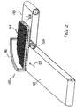
- FIG. 2 illustrates another embodiment of a touchless rail for guiding products, such as aluminum cans in a conveyor 110 through a transfer zone 126 between a first conveyor belt 122 moving in a first direction 124 and a second conveyor belt 130 moving in a second direction 128.
- the touchless rail 140 of FIG. 2 comprises a curved linear induction motor (LIM) that curves along product path through the transfer zone 126.
- the curved rail 140 employs a singled coil shaped in a circular arc, or multiple coils arranged in an arc.
- the illustrative arc is 90°, though the invention is not so limited.
- the curved rail 140 generates a propagating magnetic field that induces opposing currents in a conveyed product, illustrated as aluminum cans 160, creating a repelling force on the aluminum cans to propel the cans through a transfer zone 126 and onto the second conveyor belt 130.
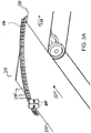
- FIG. 3A shows a conveyor 210 having a touchless guide rail in a transfer zone 226, the touchless guide rail formed using an array of permanent magnets 240.
- the first conveyor belt 222 moves in direction 224.
- the permanent magnet array creates a magnetic field that induces eddy drag on the outer cans closest to the array 240, facilitating transfer of the cans onto a second conveyor belt 230, moving in direction 228, with low contact force.
- the magnets in array 240 may have alternating polarity, the same polarity or comprise a Halbach array.
- FIG. 3B shows the progression of cans 260 through the transfer zone 226. As shown, the repelling force generated by the magnetic array 240 retards the motion of the outer cans, causing fluid motion of the can group, reducing pressure on the individual cans.
- a conveyor in another embodiment, includes one or more touchless side rails for guiding product along a product path, as shown in FIG. 4 , 5A and 5B .
- a conveyor belt 322 moving in direction 324 includes one or more side rails 341, 342 comprising a permanent magnet array.
- the side rails 341, 342 are adjacent to the product path.
- the permanent magnet arrays induces an eddy drag on the outer cans 351 in the set of conveyed aluminum cans, allowing the inner cans 352 to flow forward, similar to fluid in a pipe.
- the eddy drag in the outer cans 351 cushions the cans and protects them from damage while promoting conveyance of the cans along the product path.
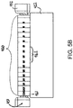
- a conveyor belt 422 moving in direction 424 includes side rails 451, 452 comprising linear induction motors (LIMs).
- the LIMs 451, 452 generate a repelling force on outer cans 461 in a set of aluminum cans 460, repelling the outer cans from the side rails 451, 452 to reduce potential damage while causing the inner cans 462 to flow forward.
- FIGS. 6A - 6C are sequential top views of a guide device 540 and aluminum can 560 during propagation of a magnetic field.
- the field V propagates from left to right, creating a field shown by the field lines 542, which induce currents in the can 560.
- FIG. 7 shows a can 560 having currents I induced by the guide device 540 according to one embodiment of the invention.
- the induced currents in the can generate a field opposing the field generated by the guide device 540, causing the can to be propelled forward and rotated in the direction of ⁇ .
- the net force would be at about a 30° angle from the face of the coil 540.
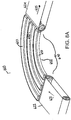
- FIGS. 8A and 8B show another embodiment of a touchless guide adjacent a product path for guiding product along the product path in a conveyor.
- the touchless guide 650 is disposed below the product path to motivate the cans, or other product, from the bottom direction.
- the conveyor 610 of FIGS. 8A and 8B comprises a first conveyor belt 622 moving in direction 621, a second conveyor belt 624 moving in direction 625 and a junction zone 640 between the first and second conveyor belt comprising a plurality of curved rails 651, 652, 653 below the product path in the junction zone 640.
- Each curved rail 651, 652, 653 comprises a linear induction motor (LIM).
- LIM linear induction motor
- a low friction surface 660 is disposed directly above the rails 651, 652, 653 to form the product path in the transfer zone 640.
- the curved LIMs are activated to propel the cans 670 around and through the 90° junction zone 640.
- FIG. 9 shows another embodiment of a conveyor 710 employing a touchless guide for guiding product along an adjacent product path.
- the touchless guide 740 of FIG. 9 comprises an array of linear induction motors (LIMs) 741.
- LIMs linear induction motors
- a low friction surface 761 directly above the array 740 forms the product path of the conveyor 710 in a transfer zone 760.
- the LIMS 741 have varying drive angles to drive the cans en masse from the bottom around the 90° transfer zone 760 between a first conveyor belt 722 and a second conveyor belt 724.
- a touchless guide such as a LIM or array of alternating permanent magnets
- the use of a touchless guide to generate repelling forces on delicate conveyed products ensures a smooth transfer between belts or smooth conveyance on a single belt.
- the touchless guide may prevent tipping and minimize damage. With few or no moving parts, the touchless guide is cleanable and requires little to no maintenance.
Landscapes
- Engineering & Computer Science (AREA)
- Mechanical Engineering (AREA)
- Non-Mechanical Conveyors (AREA)
- Framework For Endless Conveyors (AREA)
- Belt Conveyors (AREA)
- Structure Of Belt Conveyors (AREA)
Abstract
Description
- The present invention claims priority to
U.S. Provisional Patent Application Serial Number 61/990,242, filed May 8, 2014 - The invention relates generally to power-driven conveyors and more particularly to the conveyance of articles containing an electrically-conductive material.
- Conveyors are often used to transport articles through a manufacturing process. In some circumstances, the transportation of aluminum beverage cans through a can manufacturing process can be difficult in transition points, where the cans need to be transferred from one process step to the next. The lightweight cans are fragile and may be prone to tipping, which makes them susceptible to stranding on transfer dead plates. Such problems require manual intervention by operators, which can increase cost and risk potential contamination. In addition, the stranding of cans on the process line can result in costly mixing of can batches if all stranded cans are not removed from the process line.
- One version of a conveyor embodying features of the invention comprises a conveyor belt and a touchless guide device that generate a repelling force to guide products along a product path in a conveyor.
- According to one aspect of the invention, a conveyor comprises a conveyor belt for conveying articles along a product path and a guide device positioned relative to the conveyor belt adjacent the product path for generating a repellent force on conveyed articles to direct the conveyed articles along the product path.
- According to another aspect of the invention, a conveyor comprises a conveyor belt for conveying articles along a product path and a guide device for touchlessly guiding the articles along the product path without mechanically contacting the articles.
- According to another aspect, a method of guiding a product on a conveyor belt comprises the steps of conveying a product comprising an electrically conductive material along a product path at a first conveyance speed and generating a repelling force on the product to guide the product along the product along the product path using a guide device.
- These aspects and features of the invention are described in more detail in the following description, appended claims, and accompanying drawings, in which:
-
FIG. 1 is an isometric view of a transfer point of a conveyor including a touchless rail comprising a linear induction motor according to one embodiment of the invention; -
FIG. 2 is an isometric view of a transfer point of a conveyor including a curved touchless rail comprising a linear induction motor according to another embodiment of the invention; -
FIG. 3A is a schematic view of a junction in a conveyor having a touchless rail comprising alternating permanent magnets according to another embodiment of the invention; -
FIG. 3B shows the junction ofFIG. 3A while conveying a number of aluminum cans; -
FIG. 4 shows a conveyor having touchless side rails formed by an array of alternating permanent magnets according to another embodiment of the invention; -
FIG. 5A shows a conveyor having touchless side rails comprising linear induction motors according to another embodiment of the invention; -
FIG. 5B is a front view of the conveyor ofFIG. 5A ; -
FIGS 6A - 6C are sequential top views of a guide device and aluminum can during propagation of a magnetic field; -
FIG. 7 shows a can having a current induced by a guide device according to one embodiment of the invention; -
FIG. 8A shows a conveyor junction comprising nested curved rails comprising linear induction motors according to another embodiment of the invention; -
FIG. 8B shows the conveyor junction ofFIG. 8A while conveying a set of cans; and -
FIG. 9 shows a conveyor junction comprising an array of linear induction motors for guiding product according to another embodiment. - A conveyor employs a guide device for generating a repelling force to propel product along a product path with little or no contact. The guide device may comprise a linear induction motor, permanent magnet array or other device that generates a repelling force to repel the product away from the guide device and along the product path with little or no contact with the product. Aspects of the invention will be described with reference to certain illustrative embodiments, though the invention is not limited to those illustrative embodiments.
- A portion of a conveyor embodying features of the invention is shown in
FIG. 1 . Theconveyor 10 transports products along a product path and comprises afirst conveyor belt 22 that advances in a first direction ofbelt travel 24. At a transfer orjunction point 26, product is transferred to asecond conveyor belt 30, which receives product from thefirst conveyor belt 22 and conveys the product in a second direction ofbelt travel 28. The belt may be driven by any conventional drive means, such assprockets 80, motor-driven drums, pulleys, or by a linear induction motor. Idle sprockets or guide elements (not shown) may be used to guide the conveyor belts, as known in the art. - The
conveyor 10 may employ a touchless rail or device for guiding conveyed product along the product path while minimizing damage to the conveyed product. For example, theillustrative conveyor 10 includes atouchless rail 40 at thetransfer point 26 adjacent to the product path for guiding conveyed product from thefirst conveyor belt 22 to thesecond conveyor belt 30. In the illustrative embodiment, the conveyed product comprisesaluminum cans 60 or another product containing a conductive material, and thetouchless rail 40 generates a repelling force, in addition to a translational force, to push the aluminum cans towards the second conveyor along a desired product path with little to no contact force. - In the embodiment of
FIG. 1 , thetouchless rail 40 comprises afirst rail 42 oriented at a first angle and positioned over thefirst conveyor belt 22 adjacent to a product path, and asecond rail 44 adjacent to and in series with thefirst rail 42. Thefirst rail 42 is shown as oriented transverse to the first direction oftravel 24, preferably at an obtuse angle. The illustrativesecond rail 44 forms a side rail on thesecond conveyor belt 30 that is substantially parallel to the second direction oftravel 28. - In the embodiment of
FIG. 1 , eachrail aluminum cans 60, in a desired direction and force the articles onto thesecond conveyor belt 30 or along another selected product path. The LIM coil forms a stator, and the electrically conductive material in the cans forms a conductor, which is pushed away from the stator by opposing fields generated in the stator and conductor. - In one embodiment, the coils of the LIM have a series of poles that are energized to create a magnetic field. The magnetic field propagates down the coil in a propagation direction 46. The propagating magnetic field passes through the conductive material in the
cans 60 adjacent to therails LIM rails transfer zone 26. In this way, product will be pushed from thefirst belt 22 tosecond belt 30 with low contact force, which prevents tipping of the cans and promotes transfer of the cans in the upright position. The vector of the repelling force depends on the particular design of the rail. Generally, the repelling force vector will be less than about 45° from the surface of the LIM. - A plurality of coils in the
LIM rails - The guide rails 42, 44 may distribute repelling forces along the full-vertical breadth of the LIM allowing the guide rail to guide the path of the product without mechanically touching the product or risking damage to thinner gauge cans. The net force may be applied to the can center of mass to prevent tipping.
- The LIM drives may be synchronized to the belt speeds, or may be synchronized to provide a change in the speed at which the product is conveyed in select locations. For example, discrete articles may be conveyed faster than other articles. The LIM speeds can be adjusted to achieve a desired product speed and-or trajectory through a conveyor.
-
FIG. 2 illustrates another embodiment of a touchless rail for guiding products, such as aluminum cans in aconveyor 110 through atransfer zone 126 between afirst conveyor belt 122 moving in afirst direction 124 and asecond conveyor belt 130 moving in asecond direction 128. Thetouchless rail 140 ofFIG. 2 comprises a curved linear induction motor (LIM) that curves along product path through thetransfer zone 126. Thecurved rail 140 employs a singled coil shaped in a circular arc, or multiple coils arranged in an arc. The illustrative arc is 90°, though the invention is not so limited. Thecurved rail 140 generates a propagating magnetic field that induces opposing currents in a conveyed product, illustrated asaluminum cans 160, creating a repelling force on the aluminum cans to propel the cans through atransfer zone 126 and onto thesecond conveyor belt 130. - Other sources can be used to generate the repelling force, and the invention is not limited to linear induction motors. For example,
FIG. 3A shows aconveyor 210 having a touchless guide rail in atransfer zone 226, the touchless guide rail formed using an array ofpermanent magnets 240. Thefirst conveyor belt 222 moves in direction 224. As afirst conveyor belt 222 brings the product containing a conductive material, such asaluminum cans 260, past thearray 240, the permanent magnet array creates a magnetic field that induces eddy drag on the outer cans closest to thearray 240, facilitating transfer of the cans onto asecond conveyor belt 230, moving indirection 228, with low contact force. One skilled in the art will be able to determine a suitable size, strength, orientation of the magnets to sufficiently repel the cans and propel the cans along a desired trajectory. The magnets inarray 240 may have alternating polarity, the same polarity or comprise a Halbach array. -
FIG. 3B shows the progression ofcans 260 through thetransfer zone 226. As shown, the repelling force generated by themagnetic array 240 retards the motion of the outer cans, causing fluid motion of the can group, reducing pressure on the individual cans. - In another embodiment of the invention, a conveyor includes one or more touchless side rails for guiding product along a product path, as shown in
FIG. 4 ,5A and5B . In the embodiment ofFIG. 4 , aconveyor belt 322 moving indirection 324 includes one or more side rails 341, 342 comprising a permanent magnet array. The side rails 341, 342 are adjacent to the product path. As theconveyor belt 322 moves the product, illustrated as a collection ofaluminum cans 360, past therails outer cans 351 in the set of conveyed aluminum cans, allowing theinner cans 352 to flow forward, similar to fluid in a pipe. The eddy drag in theouter cans 351 cushions the cans and protects them from damage while promoting conveyance of the cans along the product path. - As shown in
FIGS. 5A and5B , in another embodiment, aconveyor belt 422 moving in direction 424 includes side rails 451, 452 comprising linear induction motors (LIMs). TheLIMs outer cans 461 in a set ofaluminum cans 460, repelling the outer cans from the side rails 451, 452 to reduce potential damage while causing theinner cans 462 to flow forward. -
FIGS. 6A - 6C are sequential top views of aguide device 540 and aluminum can 560 during propagation of a magnetic field. The field V propagates from left to right, creating a field shown by thefield lines 542, which induce currents in thecan 560.FIG. 7 shows a can 560 having currents I induced by theguide device 540 according to one embodiment of the invention. The induced currents in the can generate a field opposing the field generated by theguide device 540, causing the can to be propelled forward and rotated in the direction of ω. Generally, the net force would be at about a 30° angle from the face of thecoil 540. -
FIGS. 8A and8B show another embodiment of a touchless guide adjacent a product path for guiding product along the product path in a conveyor. In the embodiment ofFIGS. 8A and8B , thetouchless guide 650 is disposed below the product path to motivate the cans, or other product, from the bottom direction. Theconveyor 610 ofFIGS. 8A and8B comprises afirst conveyor belt 622 moving indirection 621, asecond conveyor belt 624 moving indirection 625 and ajunction zone 640 between the first and second conveyor belt comprising a plurality ofcurved rails junction zone 640. Eachcurved rail FIG. 8B , alow friction surface 660 is disposed directly above therails transfer zone 640. The curved LIMs are activated to propel thecans 670 around and through the 90°junction zone 640. -
FIG. 9 shows another embodiment of aconveyor 710 employing a touchless guide for guiding product along an adjacent product path. Thetouchless guide 740 ofFIG. 9 comprises an array of linear induction motors (LIMs) 741. Alow friction surface 761 directly above thearray 740 forms the product path of theconveyor 710 in atransfer zone 760. TheLIMS 741 have varying drive angles to drive the cans en masse from the bottom around the 90°transfer zone 760 between afirst conveyor belt 722 and asecond conveyor belt 724. - The use of a touchless guide, such as a LIM or array of alternating permanent magnets, to generate repelling forces on delicate conveyed products ensures a smooth transfer between belts or smooth conveyance on a single belt. The touchless guide may prevent tipping and minimize damage. With few or no moving parts, the touchless guide is cleanable and requires little to no maintenance.
- The invention has been described relative to certain illustrative embodiments, though the invention is not limited to those illustrative embodiments.
- The present invention will now be described by way of reference to the following clauses:
- 1. A conveyor, comprising:
- a conveyor belt for conveying articles along a product path; and
- a guide device positioned relative to the conveyor belt adjacent the product path for generating a repellent force on conveyed articles to direct the conveyed articles along the product path.
- 2. The conveyor of clause 1, wherein the guide device generates a magnetic field as the repellent force.
- 3. The conveyor of clause 1, wherein the guide device is a rail disposed adjacent to the product path.
- 4. The conveyor of clause 3, wherein the rail is curved.
- 5. The conveyor of clause 1, wherein the guide device comprises a linear induction motor.
- 6. The conveyor of clause 1, wherein the guide device comprises an array of alternating permanent magnets, an array of unipolar magnets or an array of Halbach magnets.
- 7. The conveyor of clause 1, wherein the guide device comprises a grid of linear induction motors below the product path.
- 8. The conveyor of clause 1, further comprising a low friction surface between the product path and the guide device.
- 9. A conveyor, comprising
- a conveyor belt for conveying articles along a product path; and
- a guide device for touchlessly guiding the articles along the product path without mechanically contacting the articles.
- 10. The conveyor of clause 9, wherein the guide device comprises a linear induction motor.
- 11. The conveyor of clause 9, wherein the guide device comprises an array of alternating permanent magnets.
- 12. The conveyor of clause 9, wherein the guide device is a curved rail.
- 13. The conveyor of clause 9, wherein the guide device is disposed below the product path.
- 14. The conveyor of clause 9, further comprising a low friction surface between the product path and the guide device.
- 15. A method of guiding a product on a conveyor belt, comprising the steps of:
- conveying a product comprising an electrically conductive material along a product path at a first conveyance speed; and
- and generating a repelling force on the product to guide the product along the product along the product path using a guide device.
- 16. The method of clause 15, wherein the product comprises an aluminum can.
- 17. The method of clause 15, wherein the guide device comprises a linear induction motor.
- 18. The method of clause 15, wherein the guide device comprises an array of alternating permanent magnets, an array of unipolar magnets or an array of Halbach magnets.
Claims (10)
- A conveyor, comprising:a first conveyor for conveying articles along a product path;a junction zone for transferring product from the first conveyor to a second conveyor, the junction zone comprising a plurality of curved rails below the product path for generating a repellent force on conveyed articles to direct the conveyed articles along the product path; anda low friction surface above the plurality of curved rails forming the product path.
- The conveyor of claim 1, wherein each curved rail is a linear induction motor.
- The conveyor of claim 1, wherein the curved rails curve 90° through the junction zone.
- The conveyor of claim 1, further comprising a second conveyor for receiving the conveyed articles from the junction zone.
- The conveyor of claim 1, wherein the conveyed articles comprise aluminum cans.
- A method of conveying a product comprising an electrically conductive material, comprising the steps of:conveying the product comprising an electrically conductive material along a product path using a first conveyor;passing the product to junction zone comprising a low friction surface directly above a plurality of curved rails;generating a repelling force on the product to guide the product through the junction zone using the plurality of curved rails.
- The method of claim 6, wherein each curved rail is a linear induction motor, and the linear induction motors are activated to generate the repelling force on the product.
- The method of claim 6, wherein the curved rails curve 90° through the junction zone.
- The method of claim 6, further comprising the step of transferring the product to a second conveyor for conveying the product from the junction zone.
- The method of claim 6, wherein the product comprises a plurality of aluminum cans.
Applications Claiming Priority (3)
| Application Number | Priority Date | Filing Date | Title |
|---|---|---|---|
| US201461990242P | 2014-05-08 | 2014-05-08 | |
| PCT/US2015/029602 WO2015171851A1 (en) | 2014-05-08 | 2015-05-07 | Touchless guide device for a conveyor |
| EP15789516.0A EP3140229B1 (en) | 2014-05-08 | 2015-05-07 | Touchless guide device for a conveyor |
Related Parent Applications (2)
| Application Number | Title | Priority Date | Filing Date |
|---|---|---|---|
| EP15789516.0A Division-Into EP3140229B1 (en) | 2014-05-08 | 2015-05-07 | Touchless guide device for a conveyor |
| EP15789516.0A Division EP3140229B1 (en) | 2014-05-08 | 2015-05-07 | Touchless guide device for a conveyor |
Publications (2)
| Publication Number | Publication Date |
|---|---|
| EP3578482A1 true EP3578482A1 (en) | 2019-12-11 |
| EP3578482B1 EP3578482B1 (en) | 2025-01-01 |
Family
ID=54367185
Family Applications (2)
| Application Number | Title | Priority Date | Filing Date |
|---|---|---|---|
| EP19188042.6A Active EP3578482B1 (en) | 2014-05-08 | 2015-05-07 | Touchless guide device for a conveyor |
| EP15789516.0A Active EP3140229B1 (en) | 2014-05-08 | 2015-05-07 | Touchless guide device for a conveyor |
Family Applications After (1)
| Application Number | Title | Priority Date | Filing Date |
|---|---|---|---|
| EP15789516.0A Active EP3140229B1 (en) | 2014-05-08 | 2015-05-07 | Touchless guide device for a conveyor |
Country Status (6)
| Country | Link |
|---|---|
| US (1) | US9346623B2 (en) |
| EP (2) | EP3578482B1 (en) |
| JP (1) | JP6625560B2 (en) |
| CN (1) | CN106458458B (en) |
| PL (2) | PL3578482T3 (en) |
| WO (1) | WO2015171851A1 (en) |
Families Citing this family (11)
| Publication number | Priority date | Publication date | Assignee | Title |
|---|---|---|---|---|
| JP6669740B2 (en) * | 2014-10-31 | 2020-03-18 | レイトラム,エル.エル.シー. | Conveyor system and method for spreading cans |
| WO2019078997A1 (en) * | 2017-10-17 | 2019-04-25 | Laitram, L.L.C. | Lim can mover |
| CN108058953A (en) * | 2017-12-31 | 2018-05-22 | 天津仁和鼎盛钢瓶制造有限公司 | For the steel cylinder conveyer frames of shot-blasting machine outlet |
| US10457497B1 (en) * | 2018-04-13 | 2019-10-29 | Laitram, L.L.C. | Electromagnetic conveyor system |
| US11208274B2 (en) | 2018-04-13 | 2021-12-28 | Laitram, L.L.C. | Electromagnetic conveyor system |
| CN109230292B (en) * | 2018-09-07 | 2024-03-12 | 苏州斯莱克精密设备股份有限公司 | A three-piece can digital can printing machine that rotates out cans |
| JP2021134041A (en) * | 2020-02-27 | 2021-09-13 | 三菱重工機械システム株式会社 | Transport device and transport method |
| CN112573081B (en) * | 2020-12-21 | 2022-07-22 | 重庆三峡学院 | A transfer reversing device for intelligent control |
| EP4198516B1 (en) | 2021-12-15 | 2025-07-16 | Roche Diagnostics GmbH | Laboratory automation system and use |
| EP4201846A1 (en) * | 2021-12-21 | 2023-06-28 | Bizerba SE & Co. KG | Conveyor belt |
| WO2024107526A1 (en) * | 2022-11-14 | 2024-05-23 | Laitram, L.L.C. | Conveyor system with tip prevention |
Citations (4)
| Publication number | Priority date | Publication date | Assignee | Title |
|---|---|---|---|---|
| JPS63198570A (en) * | 1987-02-10 | 1988-08-17 | Shinko Electric Co Ltd | Conveyor for metal can |
| JPS63202261A (en) * | 1987-02-14 | 1988-08-22 | Shinko Electric Co Ltd | Stagnating device for metallic can |
| JPH01133817A (en) * | 1987-11-17 | 1989-05-25 | Hitachi Kiden Kogyo Ltd | Non-ferrous metal can conveyor |
| JP2004106974A (en) * | 2002-09-17 | 2004-04-08 | Toyo Seikan Kaisha Ltd | Conveying device for goods |
Family Cites Families (36)
| Publication number | Priority date | Publication date | Assignee | Title |
|---|---|---|---|---|
| US2857059A (en) * | 1953-07-31 | 1958-10-21 | Int Standard Electric Corp | Device for storing switching information for controlling operations of conveying systems |
| FR2087171A5 (en) * | 1970-05-08 | 1971-12-31 | Saunier Duval | |
| US3830353A (en) * | 1971-03-01 | 1974-08-20 | Fleetwood Syst Inc | Method and apparatus for effecting article transfer through the use of magnetic fields |
| DE2427755C2 (en) * | 1974-06-08 | 1984-01-05 | Deutsche Itt Industries Gmbh, 7800 Freiburg | Device for measuring or processing electronic components partly made of ferromagnetic material |
| DE2801387A1 (en) * | 1978-01-13 | 1979-07-19 | Bernhard Heuft | SORTING MACHINE |
| US4351430A (en) * | 1980-05-02 | 1982-09-28 | Fleetwood Systems, Inc. | Magnetic rail construction for can conveyor |
| JPS57170324A (en) | 1981-04-10 | 1982-10-20 | Shinko Electric Co Ltd | Conveying apparatus |
| US4850542A (en) * | 1986-08-28 | 1989-07-25 | Isoreg Corporation | Winding apparatus utilizing magnetic carrier units |
| DE3711605A1 (en) * | 1987-04-07 | 1988-10-27 | Bernhard Heuft | DEVICE FOR CONTROLLING THE TRANSPORT PATH OF OBJECTS |
| US4823931A (en) * | 1988-01-07 | 1989-04-25 | Magnetic Products, Inc. | Magnetic can laner |
| JPH01210044A (en) * | 1988-02-18 | 1989-08-23 | Koujiyundo Kagaku Kenkyusho:Kk | Apparatus for separating superconductive powder |
| JPH03112393A (en) * | 1989-09-21 | 1991-05-13 | Kao Corp | Carrier |
| US5483042A (en) | 1990-06-04 | 1996-01-09 | Nordson Corporation | Magnetic separator |
| US5251741A (en) * | 1991-06-28 | 1993-10-12 | Kabushiki Kaisha Toshiba | Carrying apparatus having carrier levitated by magnetic force |
| JP2510618Y2 (en) * | 1991-09-19 | 1996-09-18 | 花王株式会社 | Article transport path conversion device |
| JP2598711Y2 (en) | 1993-06-30 | 1999-08-16 | 俊彦 清水 | Linear motor type conveyor device |
| JP2599100B2 (en) * | 1994-04-25 | 1997-04-09 | ロザイ工業株式会社 | DI can separator |
| DE9417849U1 (en) | 1994-11-08 | 1994-12-22 | NSM Magnettechnik GmbH, 59399 Olfen | Discharge device for aluminum cans or other aluminum hollow bodies |
| JPH08163712A (en) * | 1994-12-06 | 1996-06-21 | Hitachi Kiden Kogyo Ltd | Magnetically levitated carrier |
| JP2000506481A (en) * | 1996-01-26 | 2000-05-30 | エルパトローニク アクチエンゲゼルシヤフト | Method and apparatus for separating or combining container rows |
| CA2373031A1 (en) | 1999-05-06 | 2000-11-16 | Edward E. Ball | Conveyor system switch using tubular linear induction motor |
| JP4244598B2 (en) * | 2002-08-28 | 2009-03-25 | 東洋製罐株式会社 | Article transport device |
| JP5214852B2 (en) * | 2002-12-30 | 2013-06-19 | フレゼニウス カビ ドイチュラント ゲゼルシャフト ミット ベシュレンクテル ハフツング | Device for continuous supply of bags |
| JP2005026920A (en) | 2003-06-30 | 2005-01-27 | Sony Corp | Speaker diaphragm and speaker device |
| JP2006206229A (en) * | 2005-01-26 | 2006-08-10 | Toyo Seikan Kaisha Ltd | Magnetic article sorting and conveying device |
| DE102005044476A1 (en) * | 2005-09-16 | 2007-03-22 | Ernst Pennekamp Gmbh & Co. Ohg | Transporting hot glassware comprises transferring the glassware from a first conveyor belt to a second conveyor belt by means of a high-power ultrasonic field |
| KR100699271B1 (en) * | 2005-11-22 | 2007-03-28 | 삼성전자주식회사 | Conveyer |
| DE102006014616A1 (en) | 2006-03-29 | 2007-10-11 | Siemens Ag | Linear motor with differently designed secondary sections |
| JP4769202B2 (en) | 2007-01-04 | 2011-09-07 | 三井ホーム株式会社 | Architectural panel and manufacturing method thereof |
| DE112008000730A5 (en) * | 2007-01-19 | 2009-12-17 | Luk Lamellen Und Kupplungsbau Beteiligungs Kg | Adjustable magnetic conveyor for empty station |
| DE202008014282U1 (en) * | 2008-10-27 | 2010-04-01 | Iwis Antriebssysteme Gmbh & Co. Kg | Magnetic curve guide for a conveyor chain |
| KR101787306B1 (en) * | 2009-01-23 | 2017-10-18 | 마그네모션, 인코포레이티드 | Improved transport system powered by short block linear synchronous motors and switching mechanism |
| US20110022221A1 (en) * | 2009-07-24 | 2011-01-27 | Laitram, L.L.C. | Roller-belt sorter with control grid |
| DE102009056717A1 (en) * | 2009-12-04 | 2011-06-09 | Hubertus Exner | Device and method for the separation of differently electrically conductive particles |
| EP2589967A1 (en) * | 2011-11-04 | 2013-05-08 | Roche Diagnostics GmbH | Laboratory sample distribution system and corresponding method of operation |
| CH706991A1 (en) * | 2012-09-18 | 2014-03-31 | Soudronic Ag | Magnetic mounting device for can bodies. |
-
2015
- 2015-05-07 EP EP19188042.6A patent/EP3578482B1/en active Active
- 2015-05-07 CN CN201580029124.5A patent/CN106458458B/en active Active
- 2015-05-07 EP EP15789516.0A patent/EP3140229B1/en active Active
- 2015-05-07 JP JP2016566607A patent/JP6625560B2/en active Active
- 2015-05-07 PL PL19188042.6T patent/PL3578482T3/en unknown
- 2015-05-07 WO PCT/US2015/029602 patent/WO2015171851A1/en not_active Ceased
- 2015-05-07 PL PL15789516T patent/PL3140229T3/en unknown
- 2015-05-07 US US14/706,147 patent/US9346623B2/en active Active
Patent Citations (4)
| Publication number | Priority date | Publication date | Assignee | Title |
|---|---|---|---|---|
| JPS63198570A (en) * | 1987-02-10 | 1988-08-17 | Shinko Electric Co Ltd | Conveyor for metal can |
| JPS63202261A (en) * | 1987-02-14 | 1988-08-22 | Shinko Electric Co Ltd | Stagnating device for metallic can |
| JPH01133817A (en) * | 1987-11-17 | 1989-05-25 | Hitachi Kiden Kogyo Ltd | Non-ferrous metal can conveyor |
| JP2004106974A (en) * | 2002-09-17 | 2004-04-08 | Toyo Seikan Kaisha Ltd | Conveying device for goods |
Also Published As
| Publication number | Publication date |
|---|---|
| EP3140229B1 (en) | 2020-06-24 |
| WO2015171851A1 (en) | 2015-11-12 |
| PL3140229T3 (en) | 2020-11-16 |
| EP3140229A1 (en) | 2017-03-15 |
| JP6625560B2 (en) | 2019-12-25 |
| CN106458458B (en) | 2020-07-24 |
| EP3140229A4 (en) | 2018-01-10 |
| PL3578482T3 (en) | 2025-03-24 |
| US9346623B2 (en) | 2016-05-24 |
| JP2017517460A (en) | 2017-06-29 |
| CN106458458A (en) | 2017-02-22 |
| EP3578482B1 (en) | 2025-01-01 |
| US20150321854A1 (en) | 2015-11-12 |
Similar Documents
| Publication | Publication Date | Title |
|---|---|---|
| US9346623B2 (en) | Touchless guide device for a conveyor | |
| EP3212547B1 (en) | Can-spreading conveyor system and methods | |
| US9428338B2 (en) | Conveyor having rollers actuated by electromagnetic induction | |
| US9643794B2 (en) | Product-stream-transfer apparatus | |
| EP3068539B1 (en) | Electromagnetically actuated sorter | |
| JP7443428B2 (en) | monorail tray conveyor | |
| JP7421491B2 (en) | electromagnetic conveyor system | |
| JP7394053B2 (en) | Rim can mover | |
| KR101534210B1 (en) | Magnetic levitation conveyance device having steering ability | |
| IT1318125B1 (en) | FEEDING EQUIPMENT OF GROUPS OF PRODUCTS TO A CONVEYOR FOR THEIR PACKAGING. | |
| CN114502491B (en) | Linear transport system with minimum transport pitch | |
| KR102179894B1 (en) | Magnetic conveyor system | |
| BR112020018338B1 (en) | CONVEYOR SYSTEM | |
| JPS5834376B2 (en) | Conveying device for conductive long objects |
Legal Events
| Date | Code | Title | Description |
|---|---|---|---|
| PUAI | Public reference made under article 153(3) epc to a published international application that has entered the european phase |
Free format text: ORIGINAL CODE: 0009012 |
|
| STAA | Information on the status of an ep patent application or granted ep patent |
Free format text: STATUS: THE APPLICATION HAS BEEN PUBLISHED |
|
| AC | Divisional application: reference to earlier application |
Ref document number: 3140229 Country of ref document: EP Kind code of ref document: P |
|
| AK | Designated contracting states |
Kind code of ref document: A1 Designated state(s): AL AT BE BG CH CY CZ DE DK EE ES FI FR GB GR HR HU IE IS IT LI LT LU LV MC MK MT NL NO PL PT RO RS SE SI SK SM TR |
|
| STAA | Information on the status of an ep patent application or granted ep patent |
Free format text: STATUS: REQUEST FOR EXAMINATION WAS MADE |
|
| 17P | Request for examination filed |
Effective date: 20200601 |
|
| RBV | Designated contracting states (corrected) |
Designated state(s): AL AT BE BG CH CY CZ DE DK EE ES FI FR GB GR HR HU IE IS IT LI LT LU LV MC MK MT NL NO PL PT RO RS SE SI SK SM TR |
|
| STAA | Information on the status of an ep patent application or granted ep patent |
Free format text: STATUS: EXAMINATION IS IN PROGRESS |
|
| 17Q | First examination report despatched |
Effective date: 20220504 |
|
| GRAP | Despatch of communication of intention to grant a patent |
Free format text: ORIGINAL CODE: EPIDOSNIGR1 |
|
| STAA | Information on the status of an ep patent application or granted ep patent |
Free format text: STATUS: GRANT OF PATENT IS INTENDED |
|
| INTG | Intention to grant announced |
Effective date: 20240729 |
|
| GRAS | Grant fee paid |
Free format text: ORIGINAL CODE: EPIDOSNIGR3 |
|
| GRAA | (expected) grant |
Free format text: ORIGINAL CODE: 0009210 |
|
| STAA | Information on the status of an ep patent application or granted ep patent |
Free format text: STATUS: THE PATENT HAS BEEN GRANTED |
|
| P01 | Opt-out of the competence of the unified patent court (upc) registered |
Free format text: CASE NUMBER: APP_59152/2024 Effective date: 20241030 |
|
| AC | Divisional application: reference to earlier application |
Ref document number: 3140229 Country of ref document: EP Kind code of ref document: P |
|
| AK | Designated contracting states |
Kind code of ref document: B1 Designated state(s): AL AT BE BG CH CY CZ DE DK EE ES FI FR GB GR HR HU IE IS IT LI LT LU LV MC MK MT NL NO PL PT RO RS SE SI SK SM TR |
|
| REG | Reference to a national code |
Ref country code: GB Ref legal event code: FG4D |
|
| REG | Reference to a national code |
Ref country code: CH Ref legal event code: EP |
|
| REG | Reference to a national code |
Ref country code: DE Ref legal event code: R096 Ref document number: 602015090793 Country of ref document: DE |
|
| REG | Reference to a national code |
Ref country code: NL Ref legal event code: FP |
|
| REG | Reference to a national code |
Ref country code: IE Ref legal event code: FG4D |
|
| REG | Reference to a national code |
Ref country code: LT Ref legal event code: MG9D |
|
| PGFP | Annual fee paid to national office [announced via postgrant information from national office to epo] |
Ref country code: NL Payment date: 20250421 Year of fee payment: 11 |
|
| REG | Reference to a national code |
Ref country code: AT Ref legal event code: MK05 Ref document number: 1756055 Country of ref document: AT Kind code of ref document: T Effective date: 20250101 |
|
| PG25 | Lapsed in a contracting state [announced via postgrant information from national office to epo] |
Ref country code: FI Free format text: LAPSE BECAUSE OF FAILURE TO SUBMIT A TRANSLATION OF THE DESCRIPTION OR TO PAY THE FEE WITHIN THE PRESCRIBED TIME-LIMIT Effective date: 20250101 |
|
| PGFP | Annual fee paid to national office [announced via postgrant information from national office to epo] |
Ref country code: DE Payment date: 20250409 Year of fee payment: 11 |
|
| PG25 | Lapsed in a contracting state [announced via postgrant information from national office to epo] |
Ref country code: ES Free format text: LAPSE BECAUSE OF FAILURE TO SUBMIT A TRANSLATION OF THE DESCRIPTION OR TO PAY THE FEE WITHIN THE PRESCRIBED TIME-LIMIT Effective date: 20250101 |
|
| PG25 | Lapsed in a contracting state [announced via postgrant information from national office to epo] |
Ref country code: IS Free format text: LAPSE BECAUSE OF FAILURE TO SUBMIT A TRANSLATION OF THE DESCRIPTION OR TO PAY THE FEE WITHIN THE PRESCRIBED TIME-LIMIT Effective date: 20250501 Ref country code: NO Free format text: LAPSE BECAUSE OF FAILURE TO SUBMIT A TRANSLATION OF THE DESCRIPTION OR TO PAY THE FEE WITHIN THE PRESCRIBED TIME-LIMIT Effective date: 20250401 |
|
| PGFP | Annual fee paid to national office [announced via postgrant information from national office to epo] |
Ref country code: IT Payment date: 20250512 Year of fee payment: 11 |
|
| PG25 | Lapsed in a contracting state [announced via postgrant information from national office to epo] |
Ref country code: HR Free format text: LAPSE BECAUSE OF FAILURE TO SUBMIT A TRANSLATION OF THE DESCRIPTION OR TO PAY THE FEE WITHIN THE PRESCRIBED TIME-LIMIT Effective date: 20250101 |
|
| PG25 | Lapsed in a contracting state [announced via postgrant information from national office to epo] |
Ref country code: LV Free format text: LAPSE BECAUSE OF FAILURE TO SUBMIT A TRANSLATION OF THE DESCRIPTION OR TO PAY THE FEE WITHIN THE PRESCRIBED TIME-LIMIT Effective date: 20250101 Ref country code: PT Free format text: LAPSE BECAUSE OF FAILURE TO SUBMIT A TRANSLATION OF THE DESCRIPTION OR TO PAY THE FEE WITHIN THE PRESCRIBED TIME-LIMIT Effective date: 20250502 |
|
| PGFP | Annual fee paid to national office [announced via postgrant information from national office to epo] |
Ref country code: FR Payment date: 20250409 Year of fee payment: 11 |
|
| PG25 | Lapsed in a contracting state [announced via postgrant information from national office to epo] |
Ref country code: BG Free format text: LAPSE BECAUSE OF FAILURE TO SUBMIT A TRANSLATION OF THE DESCRIPTION OR TO PAY THE FEE WITHIN THE PRESCRIBED TIME-LIMIT Effective date: 20250101 Ref country code: GR Free format text: LAPSE BECAUSE OF FAILURE TO SUBMIT A TRANSLATION OF THE DESCRIPTION OR TO PAY THE FEE WITHIN THE PRESCRIBED TIME-LIMIT Effective date: 20250402 |
|
| PG25 | Lapsed in a contracting state [announced via postgrant information from national office to epo] |
Ref country code: AT Free format text: LAPSE BECAUSE OF FAILURE TO SUBMIT A TRANSLATION OF THE DESCRIPTION OR TO PAY THE FEE WITHIN THE PRESCRIBED TIME-LIMIT Effective date: 20250101 |
|
| PG25 | Lapsed in a contracting state [announced via postgrant information from national office to epo] |
Ref country code: CZ Free format text: LAPSE BECAUSE OF FAILURE TO SUBMIT A TRANSLATION OF THE DESCRIPTION OR TO PAY THE FEE WITHIN THE PRESCRIBED TIME-LIMIT Effective date: 20250101 |
|
| PG25 | Lapsed in a contracting state [announced via postgrant information from national office to epo] |
Ref country code: SE Free format text: LAPSE BECAUSE OF FAILURE TO SUBMIT A TRANSLATION OF THE DESCRIPTION OR TO PAY THE FEE WITHIN THE PRESCRIBED TIME-LIMIT Effective date: 20250101 |
|
| REG | Reference to a national code |
Ref country code: DE Ref legal event code: R097 Ref document number: 602015090793 Country of ref document: DE |
|
| PG25 | Lapsed in a contracting state [announced via postgrant information from national office to epo] |
Ref country code: SM Free format text: LAPSE BECAUSE OF FAILURE TO SUBMIT A TRANSLATION OF THE DESCRIPTION OR TO PAY THE FEE WITHIN THE PRESCRIBED TIME-LIMIT Effective date: 20250101 |
|
| PG25 | Lapsed in a contracting state [announced via postgrant information from national office to epo] |
Ref country code: DK Free format text: LAPSE BECAUSE OF FAILURE TO SUBMIT A TRANSLATION OF THE DESCRIPTION OR TO PAY THE FEE WITHIN THE PRESCRIBED TIME-LIMIT Effective date: 20250101 |
|
| PG25 | Lapsed in a contracting state [announced via postgrant information from national office to epo] |
Ref country code: EE Free format text: LAPSE BECAUSE OF FAILURE TO SUBMIT A TRANSLATION OF THE DESCRIPTION OR TO PAY THE FEE WITHIN THE PRESCRIBED TIME-LIMIT Effective date: 20250101 |
|
| PG25 | Lapsed in a contracting state [announced via postgrant information from national office to epo] |
Ref country code: RO Free format text: LAPSE BECAUSE OF FAILURE TO SUBMIT A TRANSLATION OF THE DESCRIPTION OR TO PAY THE FEE WITHIN THE PRESCRIBED TIME-LIMIT Effective date: 20250101 |
|
| PG25 | Lapsed in a contracting state [announced via postgrant information from national office to epo] |
Ref country code: SK Free format text: LAPSE BECAUSE OF FAILURE TO SUBMIT A TRANSLATION OF THE DESCRIPTION OR TO PAY THE FEE WITHIN THE PRESCRIBED TIME-LIMIT Effective date: 20250101 |
|
| PLBE | No opposition filed within time limit |
Free format text: ORIGINAL CODE: 0009261 |
|
| STAA | Information on the status of an ep patent application or granted ep patent |
Free format text: STATUS: NO OPPOSITION FILED WITHIN TIME LIMIT |
|
| REG | Reference to a national code |
Ref country code: CH Ref legal event code: L10 Free format text: ST27 STATUS EVENT CODE: U-0-0-L10-L00 (AS PROVIDED BY THE NATIONAL OFFICE) Effective date: 20251112 |
|
| 26N | No opposition filed |
Effective date: 20251002 |
|
| REG | Reference to a national code |
Ref country code: CH Ref legal event code: H13 Free format text: ST27 STATUS EVENT CODE: U-0-0-H10-H13 (AS PROVIDED BY THE NATIONAL OFFICE) Effective date: 20251223 |
|
| PG25 | Lapsed in a contracting state [announced via postgrant information from national office to epo] |
Ref country code: LU Free format text: LAPSE BECAUSE OF NON-PAYMENT OF DUE FEES Effective date: 20250507 |
|
| PG25 | Lapsed in a contracting state [announced via postgrant information from national office to epo] |
Ref country code: CH Free format text: LAPSE BECAUSE OF NON-PAYMENT OF DUE FEES Effective date: 20250531 |
|
| REG | Reference to a national code |
Ref country code: BE Ref legal event code: MM Effective date: 20250531 |
|
| PG25 | Lapsed in a contracting state [announced via postgrant information from national office to epo] |
Ref country code: MC Free format text: LAPSE BECAUSE OF FAILURE TO SUBMIT A TRANSLATION OF THE DESCRIPTION OR TO PAY THE FEE WITHIN THE PRESCRIBED TIME-LIMIT Effective date: 20250101 |
|
| PGFP | Annual fee paid to national office [announced via postgrant information from national office to epo] |
Ref country code: GB Payment date: 20260320 Year of fee payment: 12 |
|
| PG25 | Lapsed in a contracting state [announced via postgrant information from national office to epo] |
Ref country code: IE Free format text: LAPSE BECAUSE OF NON-PAYMENT OF DUE FEES Effective date: 20250507 |
|
| PG25 | Lapsed in a contracting state [announced via postgrant information from national office to epo] |
Ref country code: BE Free format text: LAPSE BECAUSE OF NON-PAYMENT OF DUE FEES Effective date: 20250531 |
|
| PGFP | Annual fee paid to national office [announced via postgrant information from national office to epo] |
Ref country code: PL Payment date: 20260319 Year of fee payment: 12 |