EP3578413A1 - Mobile discharge device for an energy storage device of an electric vehicle - Google Patents
Mobile discharge device for an energy storage device of an electric vehicle Download PDFInfo
- Publication number
- EP3578413A1 EP3578413A1 EP19173506.7A EP19173506A EP3578413A1 EP 3578413 A1 EP3578413 A1 EP 3578413A1 EP 19173506 A EP19173506 A EP 19173506A EP 3578413 A1 EP3578413 A1 EP 3578413A1
- Authority
- EP
- European Patent Office
- Prior art keywords
- electric vehicle
- energy
- discharge
- energy storage
- converting
- Prior art date
- Legal status (The legal status is an assumption and is not a legal conclusion. Google has not performed a legal analysis and makes no representation as to the accuracy of the status listed.)
- Withdrawn
Links
Images
Classifications
-
- B—PERFORMING OPERATIONS; TRANSPORTING
- B60—VEHICLES IN GENERAL
- B60L—PROPULSION OF ELECTRICALLY-PROPELLED VEHICLES; SUPPLYING ELECTRIC POWER FOR AUXILIARY EQUIPMENT OF ELECTRICALLY-PROPELLED VEHICLES; ELECTRODYNAMIC BRAKE SYSTEMS FOR VEHICLES IN GENERAL; MAGNETIC SUSPENSION OR LEVITATION FOR VEHICLES; MONITORING OPERATING VARIABLES OF ELECTRICALLY-PROPELLED VEHICLES; ELECTRIC SAFETY DEVICES FOR ELECTRICALLY-PROPELLED VEHICLES
- B60L53/00—Methods of charging batteries, specially adapted for electric vehicles; Charging stations or on-board charging equipment therefor; Exchange of energy storage elements in electric vehicles
- B60L53/10—Methods of charging batteries, specially adapted for electric vehicles; Charging stations or on-board charging equipment therefor; Exchange of energy storage elements in electric vehicles characterised by the energy transfer between the charging station and the vehicle
- B60L53/14—Conductive energy transfer
- B60L53/16—Connectors, e.g. plugs or sockets, specially adapted for charging electric vehicles
-
- B—PERFORMING OPERATIONS; TRANSPORTING
- B60—VEHICLES IN GENERAL
- B60L—PROPULSION OF ELECTRICALLY-PROPELLED VEHICLES; SUPPLYING ELECTRIC POWER FOR AUXILIARY EQUIPMENT OF ELECTRICALLY-PROPELLED VEHICLES; ELECTRODYNAMIC BRAKE SYSTEMS FOR VEHICLES IN GENERAL; MAGNETIC SUSPENSION OR LEVITATION FOR VEHICLES; MONITORING OPERATING VARIABLES OF ELECTRICALLY-PROPELLED VEHICLES; ELECTRIC SAFETY DEVICES FOR ELECTRICALLY-PROPELLED VEHICLES
- B60L55/00—Arrangements for supplying energy stored within a vehicle to a power network, i.e. vehicle-to-grid [V2G] arrangements
-
- B—PERFORMING OPERATIONS; TRANSPORTING
- B60—VEHICLES IN GENERAL
- B60L—PROPULSION OF ELECTRICALLY-PROPELLED VEHICLES; SUPPLYING ELECTRIC POWER FOR AUXILIARY EQUIPMENT OF ELECTRICALLY-PROPELLED VEHICLES; ELECTRODYNAMIC BRAKE SYSTEMS FOR VEHICLES IN GENERAL; MAGNETIC SUSPENSION OR LEVITATION FOR VEHICLES; MONITORING OPERATING VARIABLES OF ELECTRICALLY-PROPELLED VEHICLES; ELECTRIC SAFETY DEVICES FOR ELECTRICALLY-PROPELLED VEHICLES
- B60L53/00—Methods of charging batteries, specially adapted for electric vehicles; Charging stations or on-board charging equipment therefor; Exchange of energy storage elements in electric vehicles
- B60L53/30—Constructional details of charging stations
- B60L53/31—Charging columns specially adapted for electric vehicles
-
- B—PERFORMING OPERATIONS; TRANSPORTING
- B60—VEHICLES IN GENERAL
- B60L—PROPULSION OF ELECTRICALLY-PROPELLED VEHICLES; SUPPLYING ELECTRIC POWER FOR AUXILIARY EQUIPMENT OF ELECTRICALLY-PROPELLED VEHICLES; ELECTRODYNAMIC BRAKE SYSTEMS FOR VEHICLES IN GENERAL; MAGNETIC SUSPENSION OR LEVITATION FOR VEHICLES; MONITORING OPERATING VARIABLES OF ELECTRICALLY-PROPELLED VEHICLES; ELECTRIC SAFETY DEVICES FOR ELECTRICALLY-PROPELLED VEHICLES
- B60L53/00—Methods of charging batteries, specially adapted for electric vehicles; Charging stations or on-board charging equipment therefor; Exchange of energy storage elements in electric vehicles
- B60L53/60—Monitoring or controlling charging stations
-
- H—ELECTRICITY
- H01—ELECTRIC ELEMENTS
- H01M—PROCESSES OR MEANS, e.g. BATTERIES, FOR THE DIRECT CONVERSION OF CHEMICAL ENERGY INTO ELECTRICAL ENERGY
- H01M10/00—Secondary cells; Manufacture thereof
- H01M10/42—Methods or arrangements for servicing or maintenance of secondary cells or secondary half-cells
- H01M10/44—Methods for charging or discharging
-
- H—ELECTRICITY
- H02—GENERATION; CONVERSION OR DISTRIBUTION OF ELECTRIC POWER
- H02J—CIRCUIT ARRANGEMENTS OR SYSTEMS FOR SUPPLYING OR DISTRIBUTING ELECTRIC POWER; SYSTEMS FOR STORING ELECTRIC ENERGY
- H02J7/00—Circuit arrangements for charging or depolarising batteries or for supplying loads from batteries
- H02J7/0068—Battery or charger load switching, e.g. concurrent charging and load supply
-
- H—ELECTRICITY
- H02—GENERATION; CONVERSION OR DISTRIBUTION OF ELECTRIC POWER
- H02J—CIRCUIT ARRANGEMENTS OR SYSTEMS FOR SUPPLYING OR DISTRIBUTING ELECTRIC POWER; SYSTEMS FOR STORING ELECTRIC ENERGY
- H02J7/00—Circuit arrangements for charging or depolarising batteries or for supplying loads from batteries
- H02J7/34—Parallel operation in networks using both storage and other dc sources, e.g. providing buffering
- H02J7/342—The other DC source being a battery actively interacting with the first one, i.e. battery to battery charging
-
- H—ELECTRICITY
- H02—GENERATION; CONVERSION OR DISTRIBUTION OF ELECTRIC POWER
- H02J—CIRCUIT ARRANGEMENTS OR SYSTEMS FOR SUPPLYING OR DISTRIBUTING ELECTRIC POWER; SYSTEMS FOR STORING ELECTRIC ENERGY
- H02J7/00—Circuit arrangements for charging or depolarising batteries or for supplying loads from batteries
- H02J7/34—Parallel operation in networks using both storage and other dc sources, e.g. providing buffering
- H02J7/345—Parallel operation in networks using both storage and other dc sources, e.g. providing buffering using capacitors as storage or buffering devices
-
- B—PERFORMING OPERATIONS; TRANSPORTING
- B60—VEHICLES IN GENERAL
- B60L—PROPULSION OF ELECTRICALLY-PROPELLED VEHICLES; SUPPLYING ELECTRIC POWER FOR AUXILIARY EQUIPMENT OF ELECTRICALLY-PROPELLED VEHICLES; ELECTRODYNAMIC BRAKE SYSTEMS FOR VEHICLES IN GENERAL; MAGNETIC SUSPENSION OR LEVITATION FOR VEHICLES; MONITORING OPERATING VARIABLES OF ELECTRICALLY-PROPELLED VEHICLES; ELECTRIC SAFETY DEVICES FOR ELECTRICALLY-PROPELLED VEHICLES
- B60L53/00—Methods of charging batteries, specially adapted for electric vehicles; Charging stations or on-board charging equipment therefor; Exchange of energy storage elements in electric vehicles
- B60L53/10—Methods of charging batteries, specially adapted for electric vehicles; Charging stations or on-board charging equipment therefor; Exchange of energy storage elements in electric vehicles characterised by the energy transfer between the charging station and the vehicle
- B60L53/14—Conductive energy transfer
-
- H—ELECTRICITY
- H02—GENERATION; CONVERSION OR DISTRIBUTION OF ELECTRIC POWER
- H02J—CIRCUIT ARRANGEMENTS OR SYSTEMS FOR SUPPLYING OR DISTRIBUTING ELECTRIC POWER; SYSTEMS FOR STORING ELECTRIC ENERGY
- H02J2207/00—Indexing scheme relating to details of circuit arrangements for charging or depolarising batteries or for supplying loads from batteries
- H02J2207/20—Charging or discharging characterised by the power electronics converter
-
- Y—GENERAL TAGGING OF NEW TECHNOLOGICAL DEVELOPMENTS; GENERAL TAGGING OF CROSS-SECTIONAL TECHNOLOGIES SPANNING OVER SEVERAL SECTIONS OF THE IPC; TECHNICAL SUBJECTS COVERED BY FORMER USPC CROSS-REFERENCE ART COLLECTIONS [XRACs] AND DIGESTS
- Y02—TECHNOLOGIES OR APPLICATIONS FOR MITIGATION OR ADAPTATION AGAINST CLIMATE CHANGE
- Y02E—REDUCTION OF GREENHOUSE GAS [GHG] EMISSIONS, RELATED TO ENERGY GENERATION, TRANSMISSION OR DISTRIBUTION
- Y02E60/00—Enabling technologies; Technologies with a potential or indirect contribution to GHG emissions mitigation
- Y02E60/10—Energy storage using batteries
-
- Y—GENERAL TAGGING OF NEW TECHNOLOGICAL DEVELOPMENTS; GENERAL TAGGING OF CROSS-SECTIONAL TECHNOLOGIES SPANNING OVER SEVERAL SECTIONS OF THE IPC; TECHNICAL SUBJECTS COVERED BY FORMER USPC CROSS-REFERENCE ART COLLECTIONS [XRACs] AND DIGESTS
- Y02—TECHNOLOGIES OR APPLICATIONS FOR MITIGATION OR ADAPTATION AGAINST CLIMATE CHANGE
- Y02T—CLIMATE CHANGE MITIGATION TECHNOLOGIES RELATED TO TRANSPORTATION
- Y02T10/00—Road transport of goods or passengers
- Y02T10/60—Other road transportation technologies with climate change mitigation effect
- Y02T10/70—Energy storage systems for electromobility, e.g. batteries
-
- Y—GENERAL TAGGING OF NEW TECHNOLOGICAL DEVELOPMENTS; GENERAL TAGGING OF CROSS-SECTIONAL TECHNOLOGIES SPANNING OVER SEVERAL SECTIONS OF THE IPC; TECHNICAL SUBJECTS COVERED BY FORMER USPC CROSS-REFERENCE ART COLLECTIONS [XRACs] AND DIGESTS
- Y02—TECHNOLOGIES OR APPLICATIONS FOR MITIGATION OR ADAPTATION AGAINST CLIMATE CHANGE
- Y02T—CLIMATE CHANGE MITIGATION TECHNOLOGIES RELATED TO TRANSPORTATION
- Y02T10/00—Road transport of goods or passengers
- Y02T10/60—Other road transportation technologies with climate change mitigation effect
- Y02T10/7072—Electromobility specific charging systems or methods for batteries, ultracapacitors, supercapacitors or double-layer capacitors
-
- Y—GENERAL TAGGING OF NEW TECHNOLOGICAL DEVELOPMENTS; GENERAL TAGGING OF CROSS-SECTIONAL TECHNOLOGIES SPANNING OVER SEVERAL SECTIONS OF THE IPC; TECHNICAL SUBJECTS COVERED BY FORMER USPC CROSS-REFERENCE ART COLLECTIONS [XRACs] AND DIGESTS
- Y02—TECHNOLOGIES OR APPLICATIONS FOR MITIGATION OR ADAPTATION AGAINST CLIMATE CHANGE
- Y02T—CLIMATE CHANGE MITIGATION TECHNOLOGIES RELATED TO TRANSPORTATION
- Y02T90/00—Enabling technologies or technologies with a potential or indirect contribution to GHG emissions mitigation
- Y02T90/10—Technologies relating to charging of electric vehicles
- Y02T90/12—Electric charging stations
-
- Y—GENERAL TAGGING OF NEW TECHNOLOGICAL DEVELOPMENTS; GENERAL TAGGING OF CROSS-SECTIONAL TECHNOLOGIES SPANNING OVER SEVERAL SECTIONS OF THE IPC; TECHNICAL SUBJECTS COVERED BY FORMER USPC CROSS-REFERENCE ART COLLECTIONS [XRACs] AND DIGESTS
- Y02—TECHNOLOGIES OR APPLICATIONS FOR MITIGATION OR ADAPTATION AGAINST CLIMATE CHANGE
- Y02T—CLIMATE CHANGE MITIGATION TECHNOLOGIES RELATED TO TRANSPORTATION
- Y02T90/00—Enabling technologies or technologies with a potential or indirect contribution to GHG emissions mitigation
- Y02T90/10—Technologies relating to charging of electric vehicles
- Y02T90/14—Plug-in electric vehicles
-
- Y—GENERAL TAGGING OF NEW TECHNOLOGICAL DEVELOPMENTS; GENERAL TAGGING OF CROSS-SECTIONAL TECHNOLOGIES SPANNING OVER SEVERAL SECTIONS OF THE IPC; TECHNICAL SUBJECTS COVERED BY FORMER USPC CROSS-REFERENCE ART COLLECTIONS [XRACs] AND DIGESTS
- Y04—INFORMATION OR COMMUNICATION TECHNOLOGIES HAVING AN IMPACT ON OTHER TECHNOLOGY AREAS
- Y04S—SYSTEMS INTEGRATING TECHNOLOGIES RELATED TO POWER NETWORK OPERATION, COMMUNICATION OR INFORMATION TECHNOLOGIES FOR IMPROVING THE ELECTRICAL POWER GENERATION, TRANSMISSION, DISTRIBUTION, MANAGEMENT OR USAGE, i.e. SMART GRIDS
- Y04S10/00—Systems supporting electrical power generation, transmission or distribution
- Y04S10/12—Monitoring or controlling equipment for energy generation units, e.g. distributed energy generation [DER] or load-side generation
- Y04S10/126—Monitoring or controlling equipment for energy generation units, e.g. distributed energy generation [DER] or load-side generation the energy generation units being or involving electric vehicles [EV] or hybrid vehicles [HEV], i.e. power aggregation of EV or HEV, vehicle to grid arrangements [V2G]
Definitions
- the invention relates to a mobile discharge device ("mobile discharge”) for an energy storage of an electric vehicle.
- the energy storage is z. B. a high voltage battery (HV battery), which is used as a traction battery.
- HV battery high voltage battery
- the controller of the unloading device is configured to control the unloading operation.
- the control device is set up to communicate via PLC (Power Line Communication) with the electric vehicle or the electric vehicles.
- the control device is configured to monitor the discharge current and the discharge voltage during the discharge process, and to control the discharge process such that a predetermined maximum discharge current is not exceeded and a predetermined minimum discharge voltage is not undershot.
- the control device is set up to ensure that after the discharge process a predetermined residual capacity (SoC) remains in the discharged energy store.
- the predetermined residual capacity can, for. B. amount to 5% of the nominal capacity of the energy storage.
Landscapes
- Engineering & Computer Science (AREA)
- Power Engineering (AREA)
- Transportation (AREA)
- Mechanical Engineering (AREA)
- Manufacturing & Machinery (AREA)
- Chemical & Material Sciences (AREA)
- Chemical Kinetics & Catalysis (AREA)
- Electrochemistry (AREA)
- General Chemical & Material Sciences (AREA)
- Charge And Discharge Circuits For Batteries Or The Like (AREA)
- Electric Propulsion And Braking For Vehicles (AREA)
Abstract
Die Erfindung betrifft eine mobile Entladevorrichtung für einen Energiespeicher eines Elektrofahrzeugs sowie Verfahren zum Betreiben der Vorrichtung.The invention relates to a mobile discharge device for an energy storage device of an electric vehicle and a method for operating the device.
Description
Die Erfindung betrifft eine mobile Entladevorrichtung für einen Energiespeicher eines Elektrofahrzeugs sowie Verfahren zum Betreiben der Vorrichtung.The invention relates to a mobile discharge device for an energy store of an electric vehicle and to a method for operating the device.
Heutige Elektrofahrzeuge besitzen in der Regel zwei Möglichkeiten, den Hochvolt-Speicher des Fahrzeugs (die Traktionsbatterie) aufzuladen. Dies kann über eine herkömmliche Wechselspannung (AC-Laden, z. B. mit 11kW Ladeleistung) oder über eine Gleichspannung (DC-Laden, z. B. mit 150kW Ladeleistung) erfolgen.Today's electric vehicles usually have two ways to charge the high-voltage memory of the vehicle (the traction battery). This can be done via a conventional alternating voltage (AC charging, eg with 11kW charging power) or via a DC voltage (DC charging, eg with 150kW charging power).
Beide Lademöglichkeiten erfordern eine separate Absicherung, Erprobung und Freigabe. Dies stellt bei BEVs (Battery Electric Vehicles) der neusten Generation mit Reichweiten von 500km eine Herausforderung dar, denn die Ladeerprobung kann nur mit leerer Traktionsbatterie erfolgen. Aktuell gibt es nur die Möglichkeit, nach jedem Vollladeversuch die Fahrzeuge wieder "leer" zu fahren. Das führt bei einer durchschnittlichen Reichweite von 500km zu einem erheblichen Entwicklungsaufwand, längeren Erprobungszeiten und einer Einbuße an Erprobungsdauer bzw. Testzeiten. Es wird zudem ein eingewiesener Fahrer mit Prototypenführerschein benötigt.Both charging options require separate protection, testing and approval. This poses a challenge with BEVs (Battery Electric Vehicles) of the latest generation with ranges of 500km, because the loading test can only be done with an empty traction battery. Currently there is only the possibility to drive the vehicles "empty" after each full load attempt. This results in an average range of 500km to a considerable development effort, longer testing times and a loss of test duration or test times. In addition, a trained driver with prototype driver's license is required.
Die
Aus der
Aus der
Vor diesem Hintergrund hat sich die vorliegende Erfindung die Aufgabe gestellt, die Nachteile des Standes der Technik zumindest teilweise zu beseitigen.Against this background, the present invention has the object to eliminate the disadvantages of the prior art, at least partially.
Die Aufgabe wird erfindungsgemäß gelöst durch eine Vorrichtung mit den Merkmalen des Anspruchs 1 und ein Verfahren mit den Merkmalen des Anspruchs 8. Ausgestaltungen und Weiterbildungen der Erfindung ergeben sich aus den abhängigen Ansprüchen.The object is achieved by a device having the features of claim 1 and a method having the features of claim 8. refinements and developments of the invention will become apparent from the dependent claims.
Gegenstand der Erfindung ist eine mobile Entladevorrichtung ("mobile Entladesäule") für einen Energiespeicher eines Elektrofahrzeugs. Der Energiespeicher ist z. B. eine Hochspannungsbatterie (HV-Batterie), die als Traktionsbatterie eingesetzt wird.The invention relates to a mobile discharge device ("mobile discharge") for an energy storage of an electric vehicle. The energy storage is z. B. a high voltage battery (HV battery), which is used as a traction battery.
Die Entladevorrichtung umfasst mindestens einen ersten CCS-Stecker, der über ein Ladekabel mit der Vorrichtung verbunden und dafür konfiguriert ist, an eine Ladebuchse des Elektrofahrzeugs angeschlossen zu werden, Mittel zur Umwandlung von dem Energiespeicher entnommener elektrischer Energie in Wärme, Mittel zur Umwandlung von dem Energiespeicher entnommener elektrischer Energie in Wechselstrom und/oder Mittel zur Umwandlung von dem Energiespeicher entnommener elektrischer Energie in Gleichstrom, sowie ein Steuergerät, das dafür konfiguriert ist, den Entladevorgang zu steuern.The unloading device comprises at least a first CCS plug connected to the device via a charging cable and configured to be connected to a charging socket of the electric vehicle, means for converting electrical energy drawn from the energy storage into heat, means for converting the energy storage taken electrical energy into AC and / or means for converting the energy storage of electrical energy removed into DC power, and a controller, which is configured to control the discharge process.
Die erfindungsgemäße Vorrichtung umfasst mindestens einen CCS-Stecker, der über ein Ladekabel mit der Vorrichtung verbunden und dafür konfiguriert ist, an eine Ladebuchse (fahrzeugseitige Ladedose) des Elektrofahrzeugs angeschlossen zu werden. CCS steht für "Combined Charging System". Die entsprechenden Stecker sind definiert in IEC 62196, Teil 3. In einer Ausführungsform ist der Stecker vom Typ 2. Dieser Typ ist in Europa Standard. In einer anderen Ausführungsform ist der Stecker vom Typ 1. Dieser Typ ist hauptsächlich in den USA verbreitet. Die Entladung des Energiespeichers des Fahrzeuges erfolgt über die Ladedose mit Hilfe der DC-Spannung.The inventive device comprises at least one CCS plug, which is connected via a charging cable to the device and configured to be connected to a charging socket (vehicle-side charging socket) of the electric vehicle. CCS stands for Combined Charging System. The corresponding plugs are defined in IEC 62196, Part 3. In one embodiment, the plug is Type 2. This type is standard in Europe. In another embodiment, the connector is of type 1. This type is mainly used in the USA. The energy storage of the vehicle is discharged via the charging socket with the aid of the DC voltage.
Die Entladevorrichtung kann die entnommene Ladeleistung auf verschiedene Arten verwerten:
- Umwandlung der entnommenen Leistung in Wärme bei geringer Entladeleistung (bis 20kW);
- Rückspeisung der entnommenen Ladeleistung (bis 20kW) ins AC-Netz (Hausnetz);
- Rückspeisung der entnommenen Ladeleistung in ein anderes Elektrofahrzeug (bis 150kW).
- Conversion of the extracted power into heat with low discharging power (up to 20kW);
- Regenerating the withdrawn charging power (up to 20kW) into the AC network (home network);
- Regenerating the discharged charging power into another electric vehicle (up to 150kW).
In einer Ausführungsform umfassen die Mittel zur Umwandlung der dem Energiespeicher entnommenen elektrischen Energie in Wärme mindestens einen elektrischen Widerstand. Der Entladestrom wird durch den mindestens einen elektrischen Widerstand geleitet und dort in Wärme umgewandelt.In one embodiment, the means for converting the electrical energy drawn into the energy store into heat comprise at least one electrical resistance. The discharge current is passed through the at least one electrical resistance and converted there into heat.
In einer weiteren Ausführungsform umfassen die Mittel zur Umwandlung der dem Energiespeicher entnommenen elektrischen Energie in Wechselstrom einen Wechselrichter, dessen Ausgang mit einem dreiphasigen Stecker verbunden ist. Der dreiphasige Stecker kann an ein Wechselstromnetz, beispielsweise ein Hausnetz, angeschlossen werden und der in der Vorrichtung erzeugte Wechselstrom wird in das Netz eingespeist.In a further embodiment, the means for converting the electrical energy drawn into the energy store into alternating current comprise an inverter whose output is connected to a three-phase plug. The three-phase plug can be connected to an AC mains, such as a home network, and the AC current generated in the device is fed to the grid.
In einer weiteren Ausführungsform umfassen die Mittel zur Umwandlung der dem Energiespeicher entnommenen elektrischen Energie in Gleichstrom einen Gleichstromwandler (DC/DC-Wandler), dessen Ausgang mit mindestens einem zweiten CCS-Stecker verbunden ist, der dafür konfiguriert ist, an eine Ladebuchse eines zweiten Elektrofahrzeugs angeschlossen zu werden. Der Energiespeicher des zweiten Elektrofahrzeugs kann dann mit der dem Energiespeicher des ersten Elektrofahrzeugs entnommenen elektrischen Energie geladen werden. Es können auch mehrere Ladekabel mit CCS-Steckern an den Ausgang des DC/DC-Wandlers angeschlossen werden. Es können dann mehrere weitere Elektrofahrzeuge angeschlossen und deren Energiespeicher geladen werden.In a further embodiment, the means for converting the electrical energy drawn into the energy store into DC include a DC-DC converter whose output is connected to at least one second CCS plug configured to a charging socket of a second electric vehicle to be connected. The energy store of the second electric vehicle can then be charged with the electrical energy taken from the energy store of the first electric vehicle. It is also possible to connect several charging cables with CCS plugs to the output of the DC / DC converter. It can then be connected several more electric vehicles and their energy storage to be charged.
Das Steuergerät der erfindungsgemäßen Entladevorrichtung ist dafür konfiguriert, den Entladevorgang zu steuern. In einer Ausführungsform der Entladevorrichtung ist das Steuergerät dafür eingerichtet, via PLC (Power Line Communication) mit dem Elektrofahrzeug bzw. den Elektrofahrzeugen zu kommunizieren. In einer weiteren Ausführungsform ist das Steuergerät dafür eingerichtet, den Entladestrom und die Entladespannung während des Entladevorgangs zu überwachen, und den Entladevorgang so zu steuern, dass ein vorgegebener maximaler Entladestrom nicht überschritten und eine vorgegebene minimale Entladespannung nicht unterschritten wird. In einer weiteren Ausführungsform ist das Steuergerät dafür eingerichtet, sicherzustellen, dass nach dem Entladevorgang eine vorgegebene Restkapazität (SoC) im entladenen Energiespeicher verbleibt. Die vorgegebene Restkapazität kann z. B. 5% der Nennkapazität des Energiespeichers betragen. Wenn also während des Entladevorgangs eine Restladung von 5% des Energiespeichers erreicht wird, bricht das Steuergerät den Entladevorgang ab.The controller of the unloading device according to the invention is configured to control the unloading operation. In one embodiment of the unloading device, the control device is set up to communicate via PLC (Power Line Communication) with the electric vehicle or the electric vehicles. In a further embodiment, the control device is configured to monitor the discharge current and the discharge voltage during the discharge process, and to control the discharge process such that a predetermined maximum discharge current is not exceeded and a predetermined minimum discharge voltage is not undershot. In a further embodiment, the control device is set up to ensure that after the discharge process a predetermined residual capacity (SoC) remains in the discharged energy store. The predetermined residual capacity can, for. B. amount to 5% of the nominal capacity of the energy storage. Thus, when a residual charge of 5% of the energy storage is reached during the discharge, the controller aborts the discharge process.
Gegenstand der Erfindung ist auch ein Verfahren zum Entladen eines Energiespeichers eines Elektrofahrzeugs mit der erfindungsgemäßen Entladevorrichtung. Dabei wird der mindestens eine erste CCS-Stecker der Vorrichtung in eine Ladebuchse des Elektrofahrzeugs eingesteckt, und über das Ladekabel elektrische Energie (in Form von Gleichstrom) aus dem Energiespeicher des Elektrofahrzeugs entnommen und in die Vorrichtung geleitet. Das Steuergerät der Vorrichtung steuert in einer Ausführungsform des Verfahrens den Entladestrom und die Entladespannung und bricht den Entladevorgang ab, wenn die Restladung (SoC) des Energiespeichers einen vorgegebenen Schwellenwert erreicht (z. B. 5%). Die dem Energiespeicher entnommene elektrische Energie wird in der Vorrichtung wahlweise in Wärme, Wechselstrom und/oder Gleichstrom umgewandelt. In einer Ausführungsform des Verfahrens wird mit der dem Energiespeicher entnommenen elektrischen Energie der Energiespeicher eines zweiten Elektrofahrzeugs geladen. Dieses Verfahren ermöglicht Energie- und Kosteneinsparungen, da das Fahrzeug, welches entladen wird, den Energiespeicher eines anderen Fahrzeugs laden kann.The invention also provides a method for discharging an energy store of an electric vehicle with the unloading device according to the invention. In this case, the at least one first CCS plug of the device is plugged into a charging socket of the electric vehicle, and the charging cable electrical energy (in the form of direct current) from the Energy storage of the electric vehicle taken and directed into the device. In one embodiment of the method, the control device of the device controls the discharge current and the discharge voltage and terminates the discharge process when the residual charge (SoC) of the energy store reaches a predetermined threshold value (eg 5%). The electrical energy taken from the energy store is selectively converted in the device into heat, alternating current and / or direct current. In one embodiment of the method, the energy store of a second electric vehicle is charged with the electrical energy removed from the energy store. This method allows energy and cost savings since the vehicle being unloaded can charge the energy storage of another vehicle.
Die erfindungsgemäße Vorrichtung und das erfindungsgemäße Verfahren ermöglichen die Verringerung des Entwicklungsaufwands bei der Batterie- und Verfahrensentwicklung, da kein Fahrer notwendig ist, um den Energiespeicher "leerzufahren" und der damit verbundene Zeitverlust entfällt. Sie ermöglichen kürzere Erprobungszeiten, da die Erprobungszeit ausschließlich für Ladetests genutzt werden kann; und es ist eine geringere Anzahl an Erprobungsträgern notwendig.The device according to the invention and the method according to the invention make it possible to reduce the development effort in battery and process development since no driver is necessary to "empty" the energy store and the associated loss of time is eliminated. They allow shorter test times, as the trial period can only be used for loading tests; and a smaller number of trial vehicles is required.
Weitere Vorteile und Ausgestaltungen der Erfindung ergeben sich aus der Beschreibung und den beiliegenden Zeichnungen.Further advantages and embodiments of the invention will become apparent from the description and the accompanying drawings.
Es versteht sich, dass die voranstehend genannten und die nachstehend noch zu erläuternden Merkmale nicht nur in der jeweils angegebenen Kombination, sondern auch in anderen Kombinationen oder in Alleinstellung verwendbar sind, ohne den Rahmen der vorliegenden Erfindung zu verlassen.It is understood that the features mentioned above and those yet to be explained below can be used not only in the particular combination indicated, but also in other combinations or in isolation, without departing from the scope of the present invention.
Die Erfindung ist anhand von Ausführungsformen in den Zeichnungen schematisch dargestellt und wird unter Bezugnahme auf die Zeichnungen schematisch und ausführlich beschrieben. Es zeigt:
-
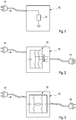
Figur 1 eine schematische Darstellung einer Ausführungsform der erfindungsgemäßen Entladevorrichtung; -
Figur 2 eine schematische Darstellung einer anderen Ausführungsform der erfindungsgemäßen Entladevorrichtung; -
Figur 3 eine schematische Darstellung einer weiteren Ausführungsform der erfindungsgemäßen Entladevorrichtung.
-
FIG. 1 a schematic representation of an embodiment of the discharge device according to the invention; -
FIG. 2 a schematic representation of another embodiment of the discharge device according to the invention; -
FIG. 3 a schematic representation of another embodiment of the discharge device according to the invention.
- 1010
- Entladevorrichtungunloader
- 1111
- CCS-SteckerCCS plug
- 1212
- Widerstandresistance
- 1313
- Wechselrichterinverter
- 1414
- dreiphasiger Steckerthree-phase plug
- 1515
- DC/DC-WandlerDC / DC converter
- 1616
- CCS-SteckerCCS plug
Claims (10)
Applications Claiming Priority (1)
| Application Number | Priority Date | Filing Date | Title |
|---|---|---|---|
| DE102018209107.2A DE102018209107A1 (en) | 2018-06-08 | 2018-06-08 | Mobile unloading device for an energy store |
Publications (1)
| Publication Number | Publication Date |
|---|---|
| EP3578413A1 true EP3578413A1 (en) | 2019-12-11 |
Family
ID=66476487
Family Applications (1)
| Application Number | Title | Priority Date | Filing Date |
|---|---|---|---|
| EP19173506.7A Withdrawn EP3578413A1 (en) | 2018-06-08 | 2019-05-09 | Mobile discharge device for an energy storage device of an electric vehicle |
Country Status (4)
| Country | Link |
|---|---|
| US (1) | US11524592B2 (en) |
| EP (1) | EP3578413A1 (en) |
| CN (1) | CN110576763B (en) |
| DE (1) | DE102018209107A1 (en) |
Families Citing this family (3)
| Publication number | Priority date | Publication date | Assignee | Title |
|---|---|---|---|---|
| DE102020204917A1 (en) | 2020-04-17 | 2021-10-21 | Dürr Systems Ag | Mobile energy system |
| CN112810475B (en) * | 2021-02-03 | 2022-05-24 | 阳光电源股份有限公司 | Charging gun interface equipment and charging pile control method |
| DE102022209663A1 (en) | 2022-09-15 | 2024-03-21 | Robert Bosch Gesellschaft mit beschränkter Haftung | Mobile discharge device and method for discharging a battery |
Citations (7)
| Publication number | Priority date | Publication date | Assignee | Title |
|---|---|---|---|---|
| DE102008032100A1 (en) | 2007-07-09 | 2009-02-19 | Fuji Jukogyo K.K. | Capacitor arrangement and power supply for a vehicle with such a capacitor arrangement |
| DE102012202465A1 (en) | 2011-02-21 | 2012-08-23 | Denso Corporation | Power supply system for supplying electric current to e.g. house to charge battery of hybrid car, has storage device storing surplus of electric solar when amount of electricity is larger than amount of electric current consumed by load |
| US20140042806A1 (en) | 2012-08-09 | 2014-02-13 | Robert Bosch Gmbh | Safety System for Vehicles for Reducing the Danger of an Electric Shock from a Battery |
| US20140117942A1 (en) * | 2012-10-31 | 2014-05-01 | Honda Motor Co., Ltd. | Hybrid electric vehicle battery discharger |
| WO2015078813A1 (en) * | 2013-11-29 | 2015-06-04 | Omicron Electronics Gmbh | Method and device for testing a traction battery of an electric vehicle |
| US20160288664A1 (en) * | 2013-11-08 | 2016-10-06 | Intelligent Electronic Systems | Method of Charging from Electric Vehicle to Electric Vehicle |
| DE102016106840A1 (en) * | 2016-04-13 | 2017-10-19 | Tim Munstermann | Energy transmission device, energy transmission system, electric vehicle charging station and electric vehicle charging method |
Family Cites Families (5)
| Publication number | Priority date | Publication date | Assignee | Title |
|---|---|---|---|---|
| EP2591944A1 (en) * | 2011-11-10 | 2013-05-15 | Alcatel Lucent | A method, a system, a computer program for discharging an energy storage of a vehicle in particular and electrical battery of an electric vehicle, having a predetermined discharge limit threshold, in particular below a maximum capacity of said energy storage |
| WO2013116678A2 (en) * | 2012-02-02 | 2013-08-08 | Robert Bosch Gmbh | System and method for discharging a battery in a vehicle after a crash |
| US9263901B2 (en) * | 2012-05-19 | 2016-02-16 | Tesla Motors, Inc. | Secondary service port for high voltage battery packs |
| AT511270B1 (en) * | 2012-05-24 | 2015-07-15 | Avl List Gmbh | Method and device for testing electric energy storage systems for driving vehicles |
| US10840722B2 (en) * | 2016-01-27 | 2020-11-17 | Vehicle Energy Japan, Inc. | Battery control device |
-
2018
- 2018-06-08 DE DE102018209107.2A patent/DE102018209107A1/en not_active Withdrawn
-
2019
- 2019-05-09 EP EP19173506.7A patent/EP3578413A1/en not_active Withdrawn
- 2019-05-22 US US16/419,588 patent/US11524592B2/en active Active
- 2019-06-05 CN CN201910486250.3A patent/CN110576763B/en active Active
Patent Citations (7)
| Publication number | Priority date | Publication date | Assignee | Title |
|---|---|---|---|---|
| DE102008032100A1 (en) | 2007-07-09 | 2009-02-19 | Fuji Jukogyo K.K. | Capacitor arrangement and power supply for a vehicle with such a capacitor arrangement |
| DE102012202465A1 (en) | 2011-02-21 | 2012-08-23 | Denso Corporation | Power supply system for supplying electric current to e.g. house to charge battery of hybrid car, has storage device storing surplus of electric solar when amount of electricity is larger than amount of electric current consumed by load |
| US20140042806A1 (en) | 2012-08-09 | 2014-02-13 | Robert Bosch Gmbh | Safety System for Vehicles for Reducing the Danger of an Electric Shock from a Battery |
| US20140117942A1 (en) * | 2012-10-31 | 2014-05-01 | Honda Motor Co., Ltd. | Hybrid electric vehicle battery discharger |
| US20160288664A1 (en) * | 2013-11-08 | 2016-10-06 | Intelligent Electronic Systems | Method of Charging from Electric Vehicle to Electric Vehicle |
| WO2015078813A1 (en) * | 2013-11-29 | 2015-06-04 | Omicron Electronics Gmbh | Method and device for testing a traction battery of an electric vehicle |
| DE102016106840A1 (en) * | 2016-04-13 | 2017-10-19 | Tim Munstermann | Energy transmission device, energy transmission system, electric vehicle charging station and electric vehicle charging method |
Also Published As
| Publication number | Publication date |
|---|---|
| US20190379225A1 (en) | 2019-12-12 |
| US11524592B2 (en) | 2022-12-13 |
| DE102018209107A1 (en) | 2019-12-12 |
| CN110576763B (en) | 2023-06-27 |
| CN110576763A (en) | 2019-12-17 |
Similar Documents
| Publication | Publication Date | Title |
|---|---|---|
| EP2611644B1 (en) | System for charging a rechargeable battery of an electric vehicle | |
| DE102015004119A1 (en) | Motor vehicle with an electrical energy storage and two charging interfaces, charging system and method | |
| EP3331720B1 (en) | Electric vehicle charging station and its control method | |
| EP3578413A1 (en) | Mobile discharge device for an energy storage device of an electric vehicle | |
| DE102009000222A1 (en) | Vehicle electrical system and method for saving energy | |
| DE102017008840A1 (en) | Electric vehicle electrical system | |
| EP3720733B1 (en) | Method for controlling an electrical system of an electrically drivable motor vehicle having a plurality of batteries, and electrical system of an electrically drivable motor vehicle | |
| DE102020006178A1 (en) | Power supply device for at least one electrical consumer, and method | |
| EP2991850A2 (en) | Device and method for operating an energy storage arrangement of a motor vehicle | |
| DE102017004467A1 (en) | Supplying electrical energy from a vehicle-external electrical charging station to an electrical system of a motor vehicle | |
| DE102017221033A1 (en) | Method for operating an electrical energy storage device for a motor vehicle and corresponding energy storage device | |
| DE102019005732A1 (en) | High-voltage system for a vehicle and method for operating a high-voltage system for a vehicle | |
| DE102016216058A1 (en) | High-voltage system for a vehicle with electrified powertrain and method for operating the same | |
| DE102016002459A1 (en) | Electrical system for an electrically driven motor vehicle | |
| DE102016208148A1 (en) | Energy storage system for an electrically powered vehicle | |
| DE102019200875A1 (en) | High-voltage battery unit for an electric vehicle | |
| DE102017212678B4 (en) | Adapter cable | |
| DE102019112228A1 (en) | Device, method and cable for feeding electrical energy into an energy network based on a mobile energy storage device | |
| DE102017217154A1 (en) | motor vehicle | |
| DE102020125970A1 (en) | Method for charging a traction battery of an electric vehicle using a charging station and charging system | |
| WO2012146306A2 (en) | Method for limiting electrical power | |
| DE102016011548A1 (en) | Building-side energy storage for the coupled charging of an electric car | |
| DE102018217295A1 (en) | Charging cable for bidirectional charging with alternating current | |
| DE102018203541A1 (en) | Method and device for charging an electrically driven or drivable motor vehicle and charging cable | |
| DE102018212191B4 (en) | Procedure for testing a charging process |
Legal Events
| Date | Code | Title | Description |
|---|---|---|---|
| PUAI | Public reference made under article 153(3) epc to a published international application that has entered the european phase |
Free format text: ORIGINAL CODE: 0009012 |
|
| AK | Designated contracting states |
Kind code of ref document: A1 Designated state(s): AL AT BE BG CH CY CZ DE DK EE ES FI FR GB GR HR HU IE IS IT LI LT LU LV MC MK MT NL NO PL PT RO RS SE SI SK SM TR |
|
| AX | Request for extension of the european patent |
Extension state: BA ME |
|
| STAA | Information on the status of an ep patent application or granted ep patent |
Free format text: STATUS: THE APPLICATION IS DEEMED TO BE WITHDRAWN |
|
| 18D | Application deemed to be withdrawn |
Effective date: 20200613 |