EP3578407A1 - Battery mounting structure - Google Patents
Battery mounting structure Download PDFInfo
- Publication number
- EP3578407A1 EP3578407A1 EP19179067.4A EP19179067A EP3578407A1 EP 3578407 A1 EP3578407 A1 EP 3578407A1 EP 19179067 A EP19179067 A EP 19179067A EP 3578407 A1 EP3578407 A1 EP 3578407A1
- Authority
- EP
- European Patent Office
- Prior art keywords
- insulating sheet
- electric power
- battery
- power terminal
- flange
- Prior art date
- Legal status (The legal status is an assumption and is not a legal conclusion. Google has not performed a legal analysis and makes no representation as to the accuracy of the status listed.)
- Granted
Links
Images



Classifications
-
- B—PERFORMING OPERATIONS; TRANSPORTING
- B60—VEHICLES IN GENERAL
- B60K—ARRANGEMENT OR MOUNTING OF PROPULSION UNITS OR OF TRANSMISSIONS IN VEHICLES; ARRANGEMENT OR MOUNTING OF PLURAL DIVERSE PRIME-MOVERS IN VEHICLES; AUXILIARY DRIVES FOR VEHICLES; INSTRUMENTATION OR DASHBOARDS FOR VEHICLES; ARRANGEMENTS IN CONNECTION WITH COOLING, AIR INTAKE, GAS EXHAUST OR FUEL SUPPLY OF PROPULSION UNITS IN VEHICLES
- B60K1/00—Arrangement or mounting of electrical propulsion units
- B60K1/04—Arrangement or mounting of electrical propulsion units of the electric storage means for propulsion
-
- B—PERFORMING OPERATIONS; TRANSPORTING
- B60—VEHICLES IN GENERAL
- B60L—PROPULSION OF ELECTRICALLY-PROPELLED VEHICLES; SUPPLYING ELECTRIC POWER FOR AUXILIARY EQUIPMENT OF ELECTRICALLY-PROPELLED VEHICLES; ELECTRODYNAMIC BRAKE SYSTEMS FOR VEHICLES IN GENERAL; MAGNETIC SUSPENSION OR LEVITATION FOR VEHICLES; MONITORING OPERATING VARIABLES OF ELECTRICALLY-PROPELLED VEHICLES; ELECTRIC SAFETY DEVICES FOR ELECTRICALLY-PROPELLED VEHICLES
- B60L3/00—Electric devices on electrically-propelled vehicles for safety purposes; Monitoring operating variables, e.g. speed, deceleration or energy consumption
- B60L3/0007—Measures or means for preventing or attenuating collisions
-
- B—PERFORMING OPERATIONS; TRANSPORTING
- B60—VEHICLES IN GENERAL
- B60L—PROPULSION OF ELECTRICALLY-PROPELLED VEHICLES; SUPPLYING ELECTRIC POWER FOR AUXILIARY EQUIPMENT OF ELECTRICALLY-PROPELLED VEHICLES; ELECTRODYNAMIC BRAKE SYSTEMS FOR VEHICLES IN GENERAL; MAGNETIC SUSPENSION OR LEVITATION FOR VEHICLES; MONITORING OPERATING VARIABLES OF ELECTRICALLY-PROPELLED VEHICLES; ELECTRIC SAFETY DEVICES FOR ELECTRICALLY-PROPELLED VEHICLES
- B60L3/00—Electric devices on electrically-propelled vehicles for safety purposes; Monitoring operating variables, e.g. speed, deceleration or energy consumption
- B60L3/0023—Detecting, eliminating, remedying or compensating for drive train abnormalities, e.g. failures within the drive train
- B60L3/0069—Detecting, eliminating, remedying or compensating for drive train abnormalities, e.g. failures within the drive train relating to the isolation, e.g. ground fault or leak current
-
- B—PERFORMING OPERATIONS; TRANSPORTING
- B60—VEHICLES IN GENERAL
- B60L—PROPULSION OF ELECTRICALLY-PROPELLED VEHICLES; SUPPLYING ELECTRIC POWER FOR AUXILIARY EQUIPMENT OF ELECTRICALLY-PROPELLED VEHICLES; ELECTRODYNAMIC BRAKE SYSTEMS FOR VEHICLES IN GENERAL; MAGNETIC SUSPENSION OR LEVITATION FOR VEHICLES; MONITORING OPERATING VARIABLES OF ELECTRICALLY-PROPELLED VEHICLES; ELECTRIC SAFETY DEVICES FOR ELECTRICALLY-PROPELLED VEHICLES
- B60L50/00—Electric propulsion with power supplied within the vehicle
- B60L50/50—Electric propulsion with power supplied within the vehicle using propulsion power supplied by batteries or fuel cells
- B60L50/60—Electric propulsion with power supplied within the vehicle using propulsion power supplied by batteries or fuel cells using power supplied by batteries
- B60L50/64—Constructional details of batteries specially adapted for electric vehicles
-
- B—PERFORMING OPERATIONS; TRANSPORTING
- B60—VEHICLES IN GENERAL
- B60L—PROPULSION OF ELECTRICALLY-PROPELLED VEHICLES; SUPPLYING ELECTRIC POWER FOR AUXILIARY EQUIPMENT OF ELECTRICALLY-PROPELLED VEHICLES; ELECTRODYNAMIC BRAKE SYSTEMS FOR VEHICLES IN GENERAL; MAGNETIC SUSPENSION OR LEVITATION FOR VEHICLES; MONITORING OPERATING VARIABLES OF ELECTRICALLY-PROPELLED VEHICLES; ELECTRIC SAFETY DEVICES FOR ELECTRICALLY-PROPELLED VEHICLES
- B60L50/00—Electric propulsion with power supplied within the vehicle
- B60L50/50—Electric propulsion with power supplied within the vehicle using propulsion power supplied by batteries or fuel cells
- B60L50/60—Electric propulsion with power supplied within the vehicle using propulsion power supplied by batteries or fuel cells using power supplied by batteries
- B60L50/66—Arrangements of batteries
-
- B—PERFORMING OPERATIONS; TRANSPORTING
- B60—VEHICLES IN GENERAL
- B60R—VEHICLES, VEHICLE FITTINGS, OR VEHICLE PARTS, NOT OTHERWISE PROVIDED FOR
- B60R16/00—Electric or fluid circuits specially adapted for vehicles and not otherwise provided for; Arrangement of elements of electric or fluid circuits specially adapted for vehicles and not otherwise provided for
- B60R16/02—Electric or fluid circuits specially adapted for vehicles and not otherwise provided for; Arrangement of elements of electric or fluid circuits specially adapted for vehicles and not otherwise provided for electric constitutive elements
- B60R16/04—Arrangement of batteries
-
- H—ELECTRICITY
- H01—ELECTRIC ELEMENTS
- H01M—PROCESSES OR MEANS, e.g. BATTERIES, FOR THE DIRECT CONVERSION OF CHEMICAL ENERGY INTO ELECTRICAL ENERGY
- H01M10/00—Secondary cells; Manufacture thereof
- H01M10/60—Heating or cooling; Temperature control
- H01M10/65—Means for temperature control structurally associated with the cells
- H01M10/658—Means for temperature control structurally associated with the cells by thermal insulation or shielding
-
- H—ELECTRICITY
- H01—ELECTRIC ELEMENTS
- H01M—PROCESSES OR MEANS, e.g. BATTERIES, FOR THE DIRECT CONVERSION OF CHEMICAL ENERGY INTO ELECTRICAL ENERGY
- H01M50/00—Constructional details or processes of manufacture of the non-active parts of electrochemical cells other than fuel cells, e.g. hybrid cells
- H01M50/20—Mountings; Secondary casings or frames; Racks, modules or packs; Suspension devices; Shock absorbers; Transport or carrying devices; Holders
- H01M50/244—Secondary casings; Racks; Suspension devices; Carrying devices; Holders characterised by their mounting method
-
- H—ELECTRICITY
- H01—ELECTRIC ELEMENTS
- H01M—PROCESSES OR MEANS, e.g. BATTERIES, FOR THE DIRECT CONVERSION OF CHEMICAL ENERGY INTO ELECTRICAL ENERGY
- H01M50/00—Constructional details or processes of manufacture of the non-active parts of electrochemical cells other than fuel cells, e.g. hybrid cells
- H01M50/20—Mountings; Secondary casings or frames; Racks, modules or packs; Suspension devices; Shock absorbers; Transport or carrying devices; Holders
- H01M50/249—Mountings; Secondary casings or frames; Racks, modules or packs; Suspension devices; Shock absorbers; Transport or carrying devices; Holders specially adapted for aircraft or vehicles, e.g. cars or trains
-
- H—ELECTRICITY
- H01—ELECTRIC ELEMENTS
- H01M—PROCESSES OR MEANS, e.g. BATTERIES, FOR THE DIRECT CONVERSION OF CHEMICAL ENERGY INTO ELECTRICAL ENERGY
- H01M50/00—Constructional details or processes of manufacture of the non-active parts of electrochemical cells other than fuel cells, e.g. hybrid cells
- H01M50/20—Mountings; Secondary casings or frames; Racks, modules or packs; Suspension devices; Shock absorbers; Transport or carrying devices; Holders
- H01M50/271—Lids or covers for the racks or secondary casings
-
- H—ELECTRICITY
- H01—ELECTRIC ELEMENTS
- H01M—PROCESSES OR MEANS, e.g. BATTERIES, FOR THE DIRECT CONVERSION OF CHEMICAL ENERGY INTO ELECTRICAL ENERGY
- H01M50/00—Constructional details or processes of manufacture of the non-active parts of electrochemical cells other than fuel cells, e.g. hybrid cells
- H01M50/50—Current conducting connections for cells or batteries
- H01M50/572—Means for preventing undesired use or discharge
- H01M50/574—Devices or arrangements for the interruption of current
- H01M50/579—Devices or arrangements for the interruption of current in response to shock
-
- B—PERFORMING OPERATIONS; TRANSPORTING
- B60—VEHICLES IN GENERAL
- B60K—ARRANGEMENT OR MOUNTING OF PROPULSION UNITS OR OF TRANSMISSIONS IN VEHICLES; ARRANGEMENT OR MOUNTING OF PLURAL DIVERSE PRIME-MOVERS IN VEHICLES; AUXILIARY DRIVES FOR VEHICLES; INSTRUMENTATION OR DASHBOARDS FOR VEHICLES; ARRANGEMENTS IN CONNECTION WITH COOLING, AIR INTAKE, GAS EXHAUST OR FUEL SUPPLY OF PROPULSION UNITS IN VEHICLES
- B60K1/00—Arrangement or mounting of electrical propulsion units
- B60K1/04—Arrangement or mounting of electrical propulsion units of the electric storage means for propulsion
- B60K2001/0405—Arrangement or mounting of electrical propulsion units of the electric storage means for propulsion characterised by their position
- B60K2001/0416—Arrangement in the rear part of the vehicle
-
- H—ELECTRICITY
- H01—ELECTRIC ELEMENTS
- H01M—PROCESSES OR MEANS, e.g. BATTERIES, FOR THE DIRECT CONVERSION OF CHEMICAL ENERGY INTO ELECTRICAL ENERGY
- H01M2200/00—Safety devices for primary or secondary batteries
- H01M2200/20—Pressure-sensitive devices
-
- H—ELECTRICITY
- H01—ELECTRIC ELEMENTS
- H01M—PROCESSES OR MEANS, e.g. BATTERIES, FOR THE DIRECT CONVERSION OF CHEMICAL ENERGY INTO ELECTRICAL ENERGY
- H01M50/00—Constructional details or processes of manufacture of the non-active parts of electrochemical cells other than fuel cells, e.g. hybrid cells
- H01M50/50—Current conducting connections for cells or batteries
- H01M50/543—Terminals
- H01M50/547—Terminals characterised by the disposition of the terminals on the cells
- H01M50/55—Terminals characterised by the disposition of the terminals on the cells on the same side of the cell
-
- H—ELECTRICITY
- H01—ELECTRIC ELEMENTS
- H01M—PROCESSES OR MEANS, e.g. BATTERIES, FOR THE DIRECT CONVERSION OF CHEMICAL ENERGY INTO ELECTRICAL ENERGY
- H01M50/00—Constructional details or processes of manufacture of the non-active parts of electrochemical cells other than fuel cells, e.g. hybrid cells
- H01M50/50—Current conducting connections for cells or batteries
- H01M50/543—Terminals
- H01M50/552—Terminals characterised by their shape
- H01M50/553—Terminals adapted for prismatic, pouch or rectangular cells
-
- Y—GENERAL TAGGING OF NEW TECHNOLOGICAL DEVELOPMENTS; GENERAL TAGGING OF CROSS-SECTIONAL TECHNOLOGIES SPANNING OVER SEVERAL SECTIONS OF THE IPC; TECHNICAL SUBJECTS COVERED BY FORMER USPC CROSS-REFERENCE ART COLLECTIONS [XRACs] AND DIGESTS
- Y02—TECHNOLOGIES OR APPLICATIONS FOR MITIGATION OR ADAPTATION AGAINST CLIMATE CHANGE
- Y02E—REDUCTION OF GREENHOUSE GAS [GHG] EMISSIONS, RELATED TO ENERGY GENERATION, TRANSMISSION OR DISTRIBUTION
- Y02E60/00—Enabling technologies; Technologies with a potential or indirect contribution to GHG emissions mitigation
- Y02E60/10—Energy storage using batteries
-
- Y—GENERAL TAGGING OF NEW TECHNOLOGICAL DEVELOPMENTS; GENERAL TAGGING OF CROSS-SECTIONAL TECHNOLOGIES SPANNING OVER SEVERAL SECTIONS OF THE IPC; TECHNICAL SUBJECTS COVERED BY FORMER USPC CROSS-REFERENCE ART COLLECTIONS [XRACs] AND DIGESTS
- Y02—TECHNOLOGIES OR APPLICATIONS FOR MITIGATION OR ADAPTATION AGAINST CLIMATE CHANGE
- Y02T—CLIMATE CHANGE MITIGATION TECHNOLOGIES RELATED TO TRANSPORTATION
- Y02T10/00—Road transport of goods or passengers
- Y02T10/60—Other road transportation technologies with climate change mitigation effect
- Y02T10/70—Energy storage systems for electromobility, e.g. batteries
Definitions
- the present disclosure relates to a battery mounting structure for mounting a battery in a luggage space of a vehicle.
- auxiliary machine battery which supplies electric power to an auxiliary machinery of a vehicle is mounted in the luggage space of the vehicle.
- Many techniques have been proposed in the related art for protecting the battery when the vehicle experiences a large impact, such as when the vehicle collides with other objects.
- JP 2002-186101 A discloses an auxiliary machine battery placed at a rear part of a rear wheel arch.
- a ventilation duct is placed between the rear wheel arch and the auxiliary machine battery.
- JP 2002-186101 A although the protection of the auxiliary machine battery during the front collision is well taken into consideration, protection of the auxiliary machine battery during a rear collision is not sufficiently considered.
- a flange of a rear pillar may protrude behind the auxiliary machine battery.
- the rear pillar is made of a metal, including the flange.
- the metal flange contacts an electric power terminal of the auxiliary machine battery during the rear collision, short-circuiting occurs.
- the terminal cover may be detached due to the impact when the rear pillar collides with the auxiliary machine battery.
- the present disclosure discloses a battery mounting structure which can prevent short-circuiting of the electric power terminal of the battery during the rear collision of the vehicle.
- a battery mounting structure for mounting a battery in a luggage space of a vehicle, comprising: a battery that is placed in the luggage space and that has a first electric power terminal which protrudes upward near a rear end of the battery; a battery cover that covers at least a part of the battery; a rear pillar that is placed at a boundary between a side surface and a back surface of the vehicle and that has a flange which protrudes to a front side; and an insulating sheet that is attached to the battery cover so as to be positioned between the first electric power terminal and the flange.
- the insulating sheet may be able to deflect in a direction toward a side of the first electric power terminal following movement of the flange when the insulating sheet is pushed by the flange.
- the insulating sheet can deform following the flange, and rupturing of the insulating sheet can be effectively prevented. With this configuration, the short-circuiting of the first electric power terminal can be more reliably prevented.
- the battery cover may comprise a pair of support parts distanced in a horizontal direction, and the insulating sheet may be supported by the pair of the support parts in a state with a marginal length in which a distance along a surface from one end to the other end of the insulating sheet is longer than a straight-line distance between the pair of the support parts.
- the marginal length in the insulating sheet By providing the marginal length in the insulating sheet, it becomes possible to cause the insulating sheet to follow the flange while suppressing a tensile load applied to the insulating sheet. With this configuration, the rupturing of the insulating sheet can be more reliably prevented, and consequently, the short-circuiting of the first electric power terminal can be more reliably prevented.
- the distance along the surface from the one end to the other end of the insulating sheet may be greater than or equal to a total distance of a distance from one of the support parts to the first electric power terminal and a distance from the other of the support parts to the first electric power terminal.
- ends of the insulating sheet may be fixed to the pair of the support parts in a state where a part of the insulating sheet is folded, and the folding of the insulating sheet may be released and the insulating sheet may be opened to the side of the first electric power terminal when the insulating sheet is pushed to the side of the first electric power terminal.
- the marginal length of the insulating sheet can be reliably secured.
- At least one of the pair of the support parts may support the insulating sheet in a slidable manner, the insulating sheet may be supported by the pair of the support parts in a state where a part of the insulating sheet is hung outside of the slidable support part, and the insulating sheet may be deflected to the side of the first electric power terminal by the hung portion being slid when the insulating sheet is pushed to the side of the first electric power terminal.
- the marginal length of the insulating sheet can be reliably secured.
- an upper end of the insulating sheet may be higher than an upper end of the first electric power terminal.
- the insulating sheet is placed between the first electric power terminal and the flange, even when the flange moves to the first electric power terminal, direct contact between the flange and the first electric power terminal can be effectively prevented, and consequently, short-circuiting of the first electric power terminal can be effectively prevented.
- FIG. 1 is a plan view of a vehicle 100 onto which a battery 22 is mounted.
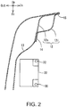
- FIG. 2 is a diagram explaining a positional relationship of the battery 22 and a rear pillar 12.
- “Fr” and “Up” represent front and upward directions of the vehicle, respectively
- “In” and “Out” represent an inner side and an outer side in a vehicle width direction, respectively.
- the battery 22 functions as a power supply of an auxiliary machinery of the vehicle 100, and is generally called an "auxiliary machine battery".
- the battery 22 is formed from, for example, a lead-acid storage battery, and an output voltage thereof is about 12V.
- the battery 22 is combined with a battery cover 24 or the like to be described later, to form a battery unit 20.
- the battery unit 20 is placed in a luggage space provided at a rear part of the vehicle.
- pillars 10a ⁇ 10d which connect a body and a roof to secure a cabin space are provided.
- four pillars are provided at each of the left and the right, and each pillar is called, in order from the front side of the vehicle, an A pillar 10a, a B pillar 10b, a C pillar 10c, and a D pillar 10d.
- the D pillar 10d is the rear pillar 12 positioned at a boundary between a side surface and a back surface of the vehicle 100.
- the rear pillar 12 is a member which extends in an up-and-down direction of the vehicle, and is normally formed from a metal.
- the rear pillar 12 is formed, for example, by joining an outer panel 12o and an inner panel 12i which respectively have an approximate L shape, and has a closed cross section with an approximate quadrangular shape. Locations where an end of the outer panel 12o and an end of the inner panel 12i are overlapped and joined become flanges 14 and 15 having an approximate flat plate shape.
- One flange 14 protrudes towards the front side of the vehicle, that is, toward the battery 22.
- other panel members for example, a decorative panel 13 forming an inner wall of the luggage space, are further attached.
- the battery 22 is placed in the luggage space in front of the rear pillar 12. Further, the battery 22 is provided with two electric power terminals 30 and 32, and is placed in an orientation such that the two electric power terminals 30 and 32 are arranged in the front and the rear. In particular, in the present example configuration, the battery 22 is placed such that the positive electric power terminal 32 is positioned at the rear side of the vehicle and the negative electric power terminal 30 is positioned at the front side of the vehicle.
- FIG. 3 is a schematic perspective diagram of the battery unit 20
- FIG. 4 is a schematic exploded perspective diagram of the battery unit 20.
- the battery unit 20 includes the battery 22 having an approximate rectangular parallelepiped shape, the battery cover 24 which covers a periphery of the battery 22, and terminal covers 26m and 26p which protect the electric power terminals 30 and 32.
- an upper front corner and an upper rear corner are cut out in an approximate rectangular parallelepiped shape, and a surface which is one stage lower than the periphery is formed. From this surface which is lower by a step, the negative electric power terminal 30 and the positive electric power terminal 32 protrude upward. Of these electric power terminals, the positive electric power terminal 32 corresponds to a first electric power terminal which protrudes upward near a rear end of the battery 22.
- the electric power terminals 30 and 32 are protected by terminal covers 26m and 26p, respectively.
- the terminal covers 26m and 26p are made of an insulating material such as a resin.
- the shape of the terminal covers 26m and 26p is not particularly limited, so long as the terminal covers can cover the periphery of the electric power terminals 30 and 32.
- ends of the terminal covers 26m and 26p extend significantly out of the battery 22
- the electric power lines 102 connected to the electric power terminals 30 and 32 extend from the bottom surfaces of the terminal covers 26m and 26p to the outside.
- the terminal covers 26m and 26p are detachably attached to the battery 22.
- the battery cover 24 is a member which covers the periphery (side surface) of the battery 22, and is made of an insulating material such as a resin. From a rear end edge of the battery cover 24, a protective wall 34 is provided in a standing manner.
- the protective wall 34 is positioned behind the positive electric power terminal 32, and an upper end of the protective wall 34 is higher than an upper end of the positive electric power terminal 32. In other words, the protective wall 34 is interposed between the flange 14 of the rear pillar 12 and the positive electric power terminal 32.
- the insulating sheet 28 is a sheet member made of an insulating material, and is, for example, a felt sheet, a nonwoven sheet or the like. Ends of the insulating sheet 28 are adhered and fixed to the protective wall 34. With this configuration, the insulating sheet 28 is interposed between the flange 14 of the rear pillar 12 and the positive electric power terminal 32.
- the insulating sheet 28 is provided to prevent electrical contact (short-circuiting) between the flange 14 made of a metal and the positive electric power terminal 32. That is, normally, the flange 14 and the positive electric power terminal 32 are distanced from each other, but when the rear collision occurs wherein other members collide at the rear side of the vehicle, the flange 14 may move toward the front along with the rear pillar 12 due to the force of the collision. In this case, if the flange 14 collides with the positive electric power terminal 32, the short-circuiting occurs. While the positive electric power terminal 32 is protected by the terminal cover 26p, because the terminal cover 26p is detachably attached as described above, the terminal cover 26p may fall off even with a relatively small impact. As a result, during the rear collision, there has been a possibility of the terminal cover 26p falling off, and the positive electric power terminal 32 exposed to the outside contacting the flange 14, causing the short-circuiting.
- the insulating sheet 28 is placed between the flange 14 and the positive electric power terminal 32, to prevent short-circuiting of the flange 14 and the positive electric power terminal 32. Further, in order to prevent rupturing of the insulating sheet 28 when the flange 14 moves to the front, in the present example configuration, the insulating sheet 28 is configured such that the insulating sheet 28 may deform following movement of the flange 14 toward the positive electric power terminal 32.
- FIGs. 5 and 6 are schematic views of the insulating sheet 28, the positive electric power terminal 32, and the flange 14.
- the ends of the insulating sheet 28 are attached to the protective wall 34 by a firm, first adhesive 37.
- a fixation position by the first adhesive 37 is a support part 36 which supports the insulating sheet 28.
- a pair of support parts 36 distanced in the horizontal direction exist on the protective wall 34 (battery cover 24), and the insulating sheet 28 is supported by the pair of the support parts 36.
- the insulating sheet 28 is attached to the protective wall 34 in a state where sides of the insulating sheet 28 are folded in a bellows shape. In other words, a distance along a surface from one end to the other end of the insulating sheet 28 is longer than a straight-line distance of the pair of the support parts 36, and the insulating sheet 28 is attached to the protective wall 34 in a state with a marginal length.
- the side portions have a multilayer structure in which a plurality of sheets are folded and overlapped, but a location facing the positive electric power terminal 32 has a single-layer structure in which sheets are not folded and overlapped.
- the folded portion is temporarily fixed by a second adhesive 38 in order to maintain the folded state.
- An adhesion force of the second adhesive 38 is sufficiently smaller than the tensile strength of the insulting sheet 28, so that when the insulating sheet 28 is pulled to the front side, the temporary fixation by the second adhesive 38 is released before the insulating sheet 28 is ruptured. So long as the state of folding with a smaller force than the tensile strength of the insulating sheet 28 can be maintained, other fixation means may be employed in place of the second adhesive 38.
- a string may be passed through a portion of the insulating sheet 28 where the sheet is folded and overlapped to form the multilayer structure, and the folded state may be maintained by a frictional force between the string and the insulating sheet 28.
- the flange 14 when the rear collision of the vehicle occurs, and the flange 14 moves toward the positive electric power terminal 32, the flange 14 first collides with the protective wall 34. Because the protective wall 34 is made of the resin and is relatively soft, as shown in FIG. 6 , the flange 14 penetrates and passes through the protective wall 34. The flange 14 passing through the protective wall 34 next collides with the insulating sheet 28. With this process, the insulating sheet 28 is pulled toward the front side of the vehicle, that is, toward the positive electric power terminal 32. With this pulling force, the temporary fixation by the second adhesive 38 is released, and the folding of the insulating sheet 28 is released. With this process, the insulating sheet 28 is put in a freely deformable state, and deforms following the flange 14 which moves toward the front side.
- the insulating sheet 28 deforms to a state of being deflected toward the front side (toward the positive electric power terminal 32).
- the insulating sheet 28 has a sufficient marginal length, a large pulling force is not applied to the insulating sheet 28, and rupturing of the insulating sheet 28 is prevented.
- FIG. 6 when the insulating sheet 28 reaches the positive electric power terminal 32 without being ruptured, the electric contact between the flange 14 and the positive electric power terminal 32 can be prevented.
- a configuration may be considered in which the insulating sheet 28 is attached to the flange 14, and not on the battery cover 24.
- the insulating sheet 28 must be attached over almost the entire surface of the flange 14, which results in a significant increase of the cost.
- the insulating sheet 28 is provided on the battery cover 24, that is, near the positive electric power terminal 32, an area of the insulating sheet 28 can be suppressed, which results in a smaller increase of the cost.
- the insulating sheet 28 can reach the positive electric power terminal 32 without being ruptured.
- the distance along the surface of the insulating sheet 28 is desirably larger than a total distance (D1+D2) of a distance D1 from one support part 36 to the positive electric power terminal 32 and a distance D2 from the other support part 36 to the positive electric power terminal 32.
- the insulating sheet 28 between the flange 14 and the positive electric power terminal 32 as in the present example configuration, the electric contact between the flange 14 and the positive electric power terminal 32 can be effectively prevented, and short-circuiting of these elements can be effectively prevented.
- the structure described above is merely exemplary, and so long as the insulating sheet 28 is interposed between the flange 14 and the positive electric power terminal 32, the other structures may be suitably changed.
- the sides of the insulating sheet 28 are folded in the bellows shape in order to provide a marginal length for the insulating sheet 28, but a number of folds and a form of the folding may be suitably changed. Therefore, for example, a structure may be employed in which, of the insulating sheet 28, only one of left and right sides is folded.
- the insulating sheet 28 does not need to be folded.
- a pair of belt holes 40 which can support the insulating sheet 28 in a slidable manner may be provided, and the insulating sheet 28 having a band shape may be inserted into the belt hole 40.
- the belt hole 40 forms the support part 36.
- the insulating sheet 28 is inserted into a pair of the belt holes 40.
- the marginal length portion is hung on an outer side in the width direction from the belt hole 40.
- expanded part 42 which is larger than a hole width of the belt hole 40, for example, a knot, may be provided on the ends of the insulating sheet 28.
- the two support parts 36 are both the belt holes 40.
- one of the two support parts 36 may be a support part 36 which supports the insulating sheet 28 in an immobile manner, for example, a firm adhesive.
- the marginal length is provided for the insulating sheet 28, but when there is a sufficient elasticity in the insulating sheet 28 itself, the marginal length does not need to be provided.
- the insulating sheet 28 when the insulating sheet 28 is formed by a sufficiently elastic insulating material, for example, a rubber or the like, the insulating sheet 28 may be attached to the protective wall 34 without the marginal length.
- the insulating sheet 28 is desirably attached at a position and with a size such that an upper end of the insulating sheet 28 is higher than an upper end of the positive electric power terminal 32.
Landscapes
- Engineering & Computer Science (AREA)
- Chemical & Material Sciences (AREA)
- Chemical Kinetics & Catalysis (AREA)
- General Chemical & Material Sciences (AREA)
- Electrochemistry (AREA)
- Mechanical Engineering (AREA)
- Transportation (AREA)
- Sustainable Development (AREA)
- Sustainable Energy (AREA)
- Power Engineering (AREA)
- Life Sciences & Earth Sciences (AREA)
- Aviation & Aerospace Engineering (AREA)
- Combustion & Propulsion (AREA)
- Manufacturing & Machinery (AREA)
- Battery Mounting, Suspending (AREA)
- Connection Of Batteries Or Terminals (AREA)
Abstract
Description
- This application claims priority to Japanese Patent Application No.
2018-109828 filed on June 7, 2018 - The present disclosure relates to a battery mounting structure for mounting a battery in a luggage space of a vehicle.
- Among vehicle-mounted batteries, there exist batteries which are placed in a luggage space of a vehicle. For example, an auxiliary machine battery which supplies electric power to an auxiliary machinery of a vehicle is mounted in the luggage space of the vehicle. Many techniques have been proposed in the related art for protecting the battery when the vehicle experiences a large impact, such as when the vehicle collides with other objects.
- For example,
JP 2002-186101 A JP 2002-186101 A - However, in
JP 2002-186101 A - Depending on a vehicle, a flange of a rear pillar may protrude behind the auxiliary machine battery. The rear pillar is made of a metal, including the flange. When the metal flange contacts an electric power terminal of the auxiliary machine battery during the rear collision, short-circuiting occurs. While the periphery of the electric power terminal is covered by a terminal cover made of an insulating material, the terminal cover may be detached due to the impact when the rear pillar collides with the auxiliary machine battery. Thus, in the techniques of the related art, there still remains room for improvement in prevention of short-circuiting of the electric power terminal of the battery during the rear collision of the vehicle.
- In light of the above, the present disclosure discloses a battery mounting structure which can prevent short-circuiting of the electric power terminal of the battery during the rear collision of the vehicle.
- According to one aspect of the present disclosure, there is provided a battery mounting structure for mounting a battery in a luggage space of a vehicle, comprising: a battery that is placed in the luggage space and that has a first electric power terminal which protrudes upward near a rear end of the battery; a battery cover that covers at least a part of the battery; a rear pillar that is placed at a boundary between a side surface and a back surface of the vehicle and that has a flange which protrudes to a front side; and an insulating sheet that is attached to the battery cover so as to be positioned between the first electric power terminal and the flange.
- By placing the insulating sheet between the first electric power terminal and the flange, even when the flange moves toward the first electric power terminal, direct contact between the flange and the first electric power terminal can be effectively prevented, and consequently, short-circuiting of the first electric power terminal can be effectively prevented.
- According to another aspect of the present disclosure, the insulating sheet may be able to deflect in a direction toward a side of the first electric power terminal following movement of the flange when the insulating sheet is pushed by the flange.
- With such a structure, the insulating sheet can deform following the flange, and rupturing of the insulating sheet can be effectively prevented. With this configuration, the short-circuiting of the first electric power terminal can be more reliably prevented.
- According to another aspect of the present disclosure, the battery cover may comprise a pair of support parts distanced in a horizontal direction, and the insulating sheet may be supported by the pair of the support parts in a state with a marginal length in which a distance along a surface from one end to the other end of the insulating sheet is longer than a straight-line distance between the pair of the support parts.
- By providing the marginal length in the insulating sheet, it becomes possible to cause the insulating sheet to follow the flange while suppressing a tensile load applied to the insulating sheet. With this configuration, the rupturing of the insulating sheet can be more reliably prevented, and consequently, the short-circuiting of the first electric power terminal can be more reliably prevented.
- According to another aspect of the present disclosure, the distance along the surface from the one end to the other end of the insulating sheet may be greater than or equal to a total distance of a distance from one of the support parts to the first electric power terminal and a distance from the other of the support parts to the first electric power terminal.
- With such a structure, it becomes possible to cause the insulting sheet to deflect until the insulting sheet reaches the first electric power terminal, and the short-circuiting of the first electric power terminal can be more reliably prevented.
- According to another aspect of the present disclosure, ends of the insulating sheet may be fixed to the pair of the support parts in a state where a part of the insulating sheet is folded, and the folding of the insulating sheet may be released and the insulating sheet may be opened to the side of the first electric power terminal when the insulating sheet is pushed to the side of the first electric power terminal.
- With such a structure, the marginal length of the insulating sheet can be reliably secured.
- According to another aspect of the present disclosure, at least one of the pair of the support parts may support the insulating sheet in a slidable manner, the insulating sheet may be supported by the pair of the support parts in a state where a part of the insulating sheet is hung outside of the slidable support part, and the insulating sheet may be deflected to the side of the first electric power terminal by the hung portion being slid when the insulating sheet is pushed to the side of the first electric power terminal.
- With such a structure, the marginal length of the insulating sheet can be reliably secured.
- According to another aspect of the present disclosure, an upper end of the insulating sheet may be higher than an upper end of the first electric power terminal.
- With such a structure, the short-circuiting of the flange and the first electric power terminal can be more reliably prevented.
- According to the battery mounting structure of the present disclosure, because the insulating sheet is placed between the first electric power terminal and the flange, even when the flange moves to the first electric power terminal, direct contact between the flange and the first electric power terminal can be effectively prevented, and consequently, short-circuiting of the first electric power terminal can be effectively prevented.
- Embodiment(s) of the present disclosure will be described based on the following figures, wherein:
-
FIG. 1 is a plan view of a vehicle onto which a battery is mounted; -
FIG. 2 is a diagram explaining a positional relationship of a battery and a rear pillar -
FIG. 3 is a schematic perspective diagram of a battery unit; -
FIG. 4 is a schematic exploded perspective diagram of a battery unit; -
FIG. 5 is a schematic view of a positive electric power terminal, an insulating sheet, and a flange; -
FIG. 6 is a schematic view of a positive electric power terminal, an insulating sheet, and a flange during a rear collision; and -
FIG. 7 is a schematic view showing another example placement of an insulating sheet. - A battery mounting structure will now be described with reference to the drawings.
FIG. 1 is a plan view of avehicle 100 onto which abattery 22 is mounted.FIG. 2 is a diagram explaining a positional relationship of thebattery 22 and arear pillar 12. In the drawings, "Fr" and "Up" represent front and upward directions of the vehicle, respectively, and "In" and "Out" represent an inner side and an outer side in a vehicle width direction, respectively. - The
battery 22 functions as a power supply of an auxiliary machinery of thevehicle 100, and is generally called an "auxiliary machine battery". Thebattery 22 is formed from, for example, a lead-acid storage battery, and an output voltage thereof is about 12V. Thebattery 22 is combined with abattery cover 24 or the like to be described later, to form abattery unit 20. Thebattery unit 20 is placed in a luggage space provided at a rear part of the vehicle. - On the
vehicle 100,pillars 10a ~ 10d which connect a body and a roof to secure a cabin space are provided. In the present example configuration, four pillars are provided at each of the left and the right, and each pillar is called, in order from the front side of the vehicle, anA pillar 10a, aB pillar 10b, aC pillar 10c, and aD pillar 10d. Of these pillars, theD pillar 10d is therear pillar 12 positioned at a boundary between a side surface and a back surface of thevehicle 100. - The
rear pillar 12 is a member which extends in an up-and-down direction of the vehicle, and is normally formed from a metal. Therear pillar 12 is formed, for example, by joining an outer panel 12o and aninner panel 12i which respectively have an approximate L shape, and has a closed cross section with an approximate quadrangular shape. Locations where an end of the outer panel 12o and an end of theinner panel 12i are overlapped and joined becomeflanges flange 14 protrudes towards the front side of the vehicle, that is, toward thebattery 22. To theflange 14, other panel members, for example, adecorative panel 13 forming an inner wall of the luggage space, are further attached. - The
battery 22 is placed in the luggage space in front of therear pillar 12. Further, thebattery 22 is provided with twoelectric power terminals electric power terminals battery 22 is placed such that the positiveelectric power terminal 32 is positioned at the rear side of the vehicle and the negativeelectric power terminal 30 is positioned at the front side of the vehicle. - Next, a structure of the
battery unit 20 having thebattery 22 as a primary element will be described with reference toFIGs. 3 and4 .FIG. 3 is a schematic perspective diagram of thebattery unit 20, andFIG. 4 is a schematic exploded perspective diagram of thebattery unit 20. Thebattery unit 20 includes thebattery 22 having an approximate rectangular parallelepiped shape, thebattery cover 24 which covers a periphery of thebattery 22, and terminal covers 26m and 26p which protect theelectric power terminals - Of the
battery 22, an upper front corner and an upper rear corner are cut out in an approximate rectangular parallelepiped shape, and a surface which is one stage lower than the periphery is formed. From this surface which is lower by a step, the negativeelectric power terminal 30 and the positiveelectric power terminal 32 protrude upward. Of these electric power terminals, the positiveelectric power terminal 32 corresponds to a first electric power terminal which protrudes upward near a rear end of thebattery 22. - The
electric power terminals terminal covers electric power terminals electric power line 102 connected to the electric power terminal to the outside. When attached to thebattery 22, ends of the terminal covers 26m and 26p extend significantly out of thebattery 22, and theelectric power lines 102 connected to theelectric power terminals electric power terminals battery 22. - The
battery cover 24 is a member which covers the periphery (side surface) of thebattery 22, and is made of an insulating material such as a resin. From a rear end edge of thebattery cover 24, aprotective wall 34 is provided in a standing manner. Theprotective wall 34 is positioned behind the positiveelectric power terminal 32, and an upper end of theprotective wall 34 is higher than an upper end of the positiveelectric power terminal 32. In other words, theprotective wall 34 is interposed between theflange 14 of therear pillar 12 and the positiveelectric power terminal 32. - Of the
protective wall 34, on a surface opposing the positiveelectric power terminal 32, an insulatingsheet 28 is attached. The insulatingsheet 28 is a sheet member made of an insulating material, and is, for example, a felt sheet, a nonwoven sheet or the like. Ends of the insulatingsheet 28 are adhered and fixed to theprotective wall 34. With this configuration, the insulatingsheet 28 is interposed between theflange 14 of therear pillar 12 and the positiveelectric power terminal 32. - The insulating
sheet 28 is provided to prevent electrical contact (short-circuiting) between theflange 14 made of a metal and the positiveelectric power terminal 32. That is, normally, theflange 14 and the positiveelectric power terminal 32 are distanced from each other, but when the rear collision occurs wherein other members collide at the rear side of the vehicle, theflange 14 may move toward the front along with therear pillar 12 due to the force of the collision. In this case, if theflange 14 collides with the positiveelectric power terminal 32, the short-circuiting occurs. While the positiveelectric power terminal 32 is protected by theterminal cover 26p, because theterminal cover 26p is detachably attached as described above, theterminal cover 26p may fall off even with a relatively small impact. As a result, during the rear collision, there has been a possibility of theterminal cover 26p falling off, and the positiveelectric power terminal 32 exposed to the outside contacting theflange 14, causing the short-circuiting. - In consideration of this, in the present example configuration, the insulating
sheet 28 is placed between theflange 14 and the positiveelectric power terminal 32, to prevent short-circuiting of theflange 14 and the positiveelectric power terminal 32. Further, in order to prevent rupturing of the insulatingsheet 28 when theflange 14 moves to the front, in the present example configuration, the insulatingsheet 28 is configured such that the insulatingsheet 28 may deform following movement of theflange 14 toward the positiveelectric power terminal 32. - The deformation will now be described with reference to
FIGs. 5 and 6. FIGs. 5 and 6 are schematic views of the insulatingsheet 28, the positiveelectric power terminal 32, and theflange 14. In the present example configuration, the ends of the insulatingsheet 28 are attached to theprotective wall 34 by a firm,first adhesive 37. A fixation position by thefirst adhesive 37 is asupport part 36 which supports the insulatingsheet 28. In other words, a pair ofsupport parts 36 distanced in the horizontal direction exist on the protective wall 34 (battery cover 24), and the insulatingsheet 28 is supported by the pair of thesupport parts 36. - The insulating
sheet 28 is attached to theprotective wall 34 in a state where sides of the insulatingsheet 28 are folded in a bellows shape. In other words, a distance along a surface from one end to the other end of the insulatingsheet 28 is longer than a straight-line distance of the pair of thesupport parts 36, and the insulatingsheet 28 is attached to theprotective wall 34 in a state with a marginal length. Of the insulatingsheet 28, the side portions have a multilayer structure in which a plurality of sheets are folded and overlapped, but a location facing the positiveelectric power terminal 32 has a single-layer structure in which sheets are not folded and overlapped. - Of the insulating
sheet 28, the folded portion is temporarily fixed by a second adhesive 38 in order to maintain the folded state. An adhesion force of thesecond adhesive 38 is sufficiently smaller than the tensile strength of theinsulting sheet 28, so that when the insulatingsheet 28 is pulled to the front side, the temporary fixation by thesecond adhesive 38 is released before the insulatingsheet 28 is ruptured. So long as the state of folding with a smaller force than the tensile strength of the insulatingsheet 28 can be maintained, other fixation means may be employed in place of thesecond adhesive 38. For example, a string may be passed through a portion of the insulatingsheet 28 where the sheet is folded and overlapped to form the multilayer structure, and the folded state may be maintained by a frictional force between the string and the insulatingsheet 28. - In the above-described structure, when the rear collision of the vehicle occurs, and the
flange 14 moves toward the positiveelectric power terminal 32, theflange 14 first collides with theprotective wall 34. Because theprotective wall 34 is made of the resin and is relatively soft, as shown inFIG. 6 , theflange 14 penetrates and passes through theprotective wall 34. Theflange 14 passing through theprotective wall 34 next collides with the insulatingsheet 28. With this process, the insulatingsheet 28 is pulled toward the front side of the vehicle, that is, toward the positiveelectric power terminal 32. With this pulling force, the temporary fixation by thesecond adhesive 38 is released, and the folding of the insulatingsheet 28 is released. With this process, the insulatingsheet 28 is put in a freely deformable state, and deforms following theflange 14 which moves toward the front side. - As a result, the insulating
sheet 28 deforms to a state of being deflected toward the front side (toward the positive electric power terminal 32). At this point, because the insulatingsheet 28 has a sufficient marginal length, a large pulling force is not applied to the insulatingsheet 28, and rupturing of the insulatingsheet 28 is prevented. As shown inFIG. 6 , when the insulatingsheet 28 reaches the positiveelectric power terminal 32 without being ruptured, the electric contact between theflange 14 and the positiveelectric power terminal 32 can be prevented. - In order to prevent the electric contact between the
flange 14 and the positiveelectric power terminal 32, a configuration may be considered in which the insulatingsheet 28 is attached to theflange 14, and not on thebattery cover 24. However, it is difficult to accurately predict the movement of theflange 14 during the rear collision, and specifying the location of collision of thelarge flange 14 with the positiveelectric power terminal 32 is not possible. Thus, in order to reliably prevent electric contact between theflange 14 and the positiveelectric power terminal 32, the insulatingsheet 28 must be attached over almost the entire surface of theflange 14, which results in a significant increase of the cost. On the other hand, if the insulatingsheet 28 is provided on thebattery cover 24, that is, near the positiveelectric power terminal 32, an area of the insulatingsheet 28 can be suppressed, which results in a smaller increase of the cost. - In order to reliably prevent the short-circuiting, it is desirable that the insulating
sheet 28 can reach the positiveelectric power terminal 32 without being ruptured. For this purpose, the distance along the surface of the insulatingsheet 28 is desirably larger than a total distance (D1+D2) of a distance D1 from onesupport part 36 to the positiveelectric power terminal 32 and a distance D2 from theother support part 36 to the positiveelectric power terminal 32. - In any case, by interposing the insulating
sheet 28 between theflange 14 and the positiveelectric power terminal 32 as in the present example configuration, the electric contact between theflange 14 and the positiveelectric power terminal 32 can be effectively prevented, and short-circuiting of these elements can be effectively prevented. The structure described above is merely exemplary, and so long as the insulatingsheet 28 is interposed between theflange 14 and the positiveelectric power terminal 32, the other structures may be suitably changed. - For example, in the above description, the sides of the insulating
sheet 28 are folded in the bellows shape in order to provide a marginal length for the insulatingsheet 28, but a number of folds and a form of the folding may be suitably changed. Therefore, for example, a structure may be employed in which, of the insulatingsheet 28, only one of left and right sides is folded. - Further, so long as the distance along the surface from the one end to the other end of the insulating
sheet 28 is larger than the distance between the pair of thesupport parts 36, that is, so long as there is the marginal length, the insulatingsheet 28 does not need to be folded. For example, as shown inFIG. 7 , a pair of belt holes 40 which can support the insulatingsheet 28 in a slidable manner may be provided, and the insulatingsheet 28 having a band shape may be inserted into thebelt hole 40. In this case, thebelt hole 40 forms thesupport part 36. In this case, the insulatingsheet 28 is inserted into a pair of the belt holes 40. Of the insulatingsheet 28, the marginal length portion is hung on an outer side in the width direction from thebelt hole 40. In order to prevent dropping off from thebelt hole 40, expandedpart 42 which is larger than a hole width of thebelt hole 40, for example, a knot, may be provided on the ends of the insulatingsheet 28. - In such a structure, when the insulating
sheet 28 is pushed toward the front side (toward the positive electric power terminal 32) by theflange 14, the insulatingsheet 28 is pulled toward the front side. In order to permit the pulling, the insulatingsheet 28 slides along thebelt hole 40. With this process, the insulatingsheet 28 becomes deformable following theflange 14, and deforms to a state of being deflected toward the positiveelectric power terminal 32. Finally, when the insulatingsheet 28 reaches the positiveelectric power terminal 32, the electric contact between theflange 14 and the positiveelectric power terminal 32 can be prevented. InFIG. 7 , the twosupport parts 36 are both the belt holes 40. Alternatively, one of the twosupport parts 36 may be asupport part 36 which supports the insulatingsheet 28 in an immobile manner, for example, a firm adhesive. - In addition, in the above description, the marginal length is provided for the insulating
sheet 28, but when there is a sufficient elasticity in the insulatingsheet 28 itself, the marginal length does not need to be provided. For example, when the insulatingsheet 28 is formed by a sufficiently elastic insulating material, for example, a rubber or the like, the insulatingsheet 28 may be attached to theprotective wall 34 without the marginal length. However, in any case, the insulatingsheet 28 is desirably attached at a position and with a size such that an upper end of the insulatingsheet 28 is higher than an upper end of the positiveelectric power terminal 32.
Claims (7)
- A battery mounting structure for mounting a battery (22) in a luggage space of a vehicle having a rear pillar (12) that is placed at a boundary between a side surface and a back surface of the vehicle and that has a flange (14) which protrudes to a front side;
the battery mounting structure comprising:a battery (22) that is to be placed in the luggage space and that has a first electric power terminal (32) which protrudes upward near a rear end of the battery (22);a battery cover (24) that covers at least a part of the battery (22);an insulating sheet (28) that is attached to the battery cover (24) so as to be positioned between the first electric power terminal (32) and the flange (14). - The battery mounting structure according to Claim 1, wherein
the insulating sheet (28) is configured to deflect in a direction toward a side of the first electric power terminal (32) following a movement of the flange (14) when the insulating sheet (28) is pushed by the flange (14). - The battery mounting structure according to Claim 1 or 2, whereinthe battery cover (24) comprises a pair of support parts (36) distanced in a horizontal direction, andthe insulating sheet (28) is supported by the pair of the support parts (36) in a state with a marginal length in which a distance along a surface from one end to the other end of the insulating sheet (28) is longer than a straight-line distance between the pair of the support parts (36).
- The battery mounting structure according to Claim 3, wherein
the distance along the surface from the one end to the other end of the insulating sheet (28) is greater than or equal to a total distance of a distance from one of the support parts (36) to the first electric power terminal (32) and a distance from the other of the support parts (36) to the first electric power terminal (32). - The battery mounting structure according to Claim 3 or 4, whereinends of the insulating sheet (28) are fixed to the pair of the support parts (36) in a state where a part of the insulating sheet (28) is folded, andthe folding of the insulating sheet (28) is configured to be released and the insulating sheet (28) to be opened to the side of the first electric power terminal (32) when the insulating sheet (28) is pushed to the side of the first electric power terminal (32).
- The battery mounting structure according to Claim 3 or 4, whereinat least one of the pair of the support parts (36) supports the insulating sheet (28) in a slidable manner,the insulating sheet (28) is supported by the pair of the support parts (36) in a state where a part of the insulating sheet (28) is hung outside of the slidable support part, andthe insulating sheet (28) is configured to be deflected to the side of the first electric power terminal (32) by the hung portion being slid when the insulating sheet (28) is pushed to the side of the first electric power terminal (32).
- The battery mounting structure according to any one of Claims 1 to 6, wherein
an upper end of the insulating sheet (28) is higher than an upper end of the first electric power terminal (32).
Applications Claiming Priority (1)
| Application Number | Priority Date | Filing Date | Title |
|---|---|---|---|
| JP2018109828A JP7006514B2 (en) | 2018-06-07 | 2018-06-07 | Battery mounting structure |
Publications (2)
| Publication Number | Publication Date |
|---|---|
| EP3578407A1 true EP3578407A1 (en) | 2019-12-11 |
| EP3578407B1 EP3578407B1 (en) | 2021-03-10 |
Family
ID=66810693
Family Applications (1)
| Application Number | Title | Priority Date | Filing Date |
|---|---|---|---|
| EP19179067.4A Active EP3578407B1 (en) | 2018-06-07 | 2019-06-07 | Battery mounting structure |
Country Status (4)
| Country | Link |
|---|---|
| US (1) | US10763476B2 (en) |
| EP (1) | EP3578407B1 (en) |
| JP (1) | JP7006514B2 (en) |
| CN (1) | CN110576812B (en) |
Cited By (2)
| Publication number | Priority date | Publication date | Assignee | Title |
|---|---|---|---|---|
| FR3104827A1 (en) * | 2019-12-17 | 2021-06-18 | Renault S.A.S. | MOTOR VEHICLE BATTERY ASSEMBLY INCLUDING INTERLOCK MEANS FOR PROTECTING THE TWO CONNECTION TERMINALS |
| WO2021151642A1 (en) * | 2020-01-30 | 2021-08-05 | Renault S.A.S | Vehicle equipped with an interposition device on a master cylinder between a master cylinder and a battery |
Families Citing this family (4)
| Publication number | Priority date | Publication date | Assignee | Title |
|---|---|---|---|---|
| US11539104B2 (en) * | 2020-04-20 | 2022-12-27 | Toyota Motor Engineering & Manufacturing North America, Inc. | Battery pillar protector |
| SE544262C2 (en) * | 2020-07-01 | 2022-03-22 | Scania Cv Ab | A method for connecting one or more electric battery units to an electrical system |
| KR20240008184A (en) * | 2022-07-11 | 2024-01-18 | 주식회사 엘지에너지솔루션 | Secondary battery having improved terminal structure |
| KR20240093032A (en) * | 2022-12-15 | 2024-06-24 | 주식회사 엘지에너지솔루션 | Insulation structure for battery module |
Citations (5)
| Publication number | Priority date | Publication date | Assignee | Title |
|---|---|---|---|---|
| JP2002186101A (en) | 2000-12-14 | 2002-06-28 | Toyota Auto Body Co Ltd | Auxiliary battery protection structure |
| WO2008088056A1 (en) * | 2007-01-16 | 2008-07-24 | Toyota Jidosha Kabushiki Kaisha | Fuel cell module for vehicles |
| DE102012011170A1 (en) * | 2012-06-06 | 2013-12-12 | GM Global Technology Operations, LLC (n.d. Ges. d. Staates Delaware) | Protective cap for a pole connection of a battery |
| DE102015013303A1 (en) * | 2015-10-13 | 2016-05-25 | Daimler Ag | Protective cover for a pole connection of a battery and motor vehicle |
| US20160248059A1 (en) * | 2015-02-20 | 2016-08-25 | Toyota Jidosha Kabushiki Kaisha | Onboard battery |
Family Cites Families (28)
| Publication number | Priority date | Publication date | Assignee | Title |
|---|---|---|---|---|
| US5343974A (en) * | 1992-07-10 | 1994-09-06 | Rabek Jan W | An electrically powered motor vehicle |
| JPH11170932A (en) * | 1997-12-12 | 1999-06-29 | Harness Syst Tech Res Ltd | Vehicle battery and vehicle safety device provided with the battery |
| DE60307750T2 (en) * | 2002-05-08 | 2006-12-14 | Nissan Motor Co., Ltd., Yokohama | Secondary cell module and method for its production |
| JP2007302140A (en) | 2006-05-12 | 2007-11-22 | Yanmar Co Ltd | Battery mounting device for working vehicle |
| FR2934927B1 (en) * | 2008-08-08 | 2011-06-03 | Renault Sas | BATTERY SUPPORT STRUCTURE FOR MOTOR VEHICLE |
| DE102009031779A1 (en) | 2009-07-06 | 2011-01-13 | GM Global Technology Operations, Inc., Detroit | Floor structure for a motor vehicle |
| WO2011016771A1 (en) * | 2009-08-05 | 2011-02-10 | Electroengine In Sweden Ab | A battery pack, an electric vehicle and a method |
| JP5483261B2 (en) * | 2010-05-11 | 2014-05-07 | スズキ株式会社 | Vehicle battery cooling device |
| JP5609804B2 (en) | 2011-07-25 | 2014-10-22 | トヨタ自動車株式会社 | Terminal protection structure and vehicle |
| US8950536B2 (en) * | 2011-12-21 | 2015-02-10 | Ford Global Technologies, Llc | Modular battery assembly support and seals |
| JP2013199196A (en) * | 2012-03-26 | 2013-10-03 | Suzuki Motor Corp | Battery pack mounting structure for electric car |
| JP2014086408A (en) | 2012-10-29 | 2014-05-12 | Suzuki Motor Corp | Vehicular battery protection structure |
| JP6048284B2 (en) * | 2013-04-03 | 2016-12-21 | スズキ株式会社 | Battery pack device for vehicle |
| JP6070993B2 (en) * | 2013-05-14 | 2017-02-01 | 本田技研工業株式会社 | Power storage device for vehicle |
| JP2015026428A (en) | 2013-07-24 | 2015-02-05 | 日産自動車株式会社 | Battery pack harness protection structure |
| US11128005B2 (en) * | 2013-07-30 | 2021-09-21 | Cps Technology Holdings Llc | Lithium ion battery with lead acid form factor |
| US10106025B2 (en) * | 2013-08-29 | 2018-10-23 | Ford Global Technologies, Llc | High voltage battery cooling plenum |
| JP6003853B2 (en) * | 2013-09-11 | 2016-10-05 | トヨタ自動車株式会社 | vehicle |
| EP3054560B1 (en) * | 2013-09-27 | 2017-12-06 | Nissan Motor Co., Ltd | Vehicle mounting structure of contactless power reception device |
| JP5871983B2 (en) * | 2014-03-28 | 2016-03-01 | 富士重工業株式会社 | Battery module protection structure mounted on the rear of the vehicle body |
| JP6221994B2 (en) * | 2014-08-08 | 2017-11-01 | 株式会社Gsユアサ | Power storage device |
| JP6521779B2 (en) * | 2015-07-23 | 2019-05-29 | 日立オートモティブシステムズ株式会社 | Secondary battery |
| JP6544311B2 (en) * | 2016-07-14 | 2019-07-17 | トヨタ自動車株式会社 | In-vehicle equipment fixed structure |
| JP6555244B2 (en) * | 2016-12-19 | 2019-08-07 | トヨタ自動車株式会社 | vehicle |
| DE102017129121A1 (en) * | 2017-10-20 | 2019-04-25 | Eberspächer Climate Control Systems GmbH & Co. KG | Electric motor driven vehicle |
| JP6958223B2 (en) * | 2017-10-20 | 2021-11-02 | トヨタ自動車株式会社 | Electric car |
| JP6879182B2 (en) * | 2017-12-01 | 2021-06-02 | トヨタ自動車株式会社 | Battery carrier |
| US10826139B2 (en) * | 2018-06-20 | 2020-11-03 | GM Global Technology Operations LLC | Battery enclosure allowing selective airflow to and from the battery enclosure |
-
2018
- 2018-06-07 JP JP2018109828A patent/JP7006514B2/en active Active
-
2019
- 2019-05-30 CN CN201910462181.2A patent/CN110576812B/en active Active
- 2019-06-05 US US16/432,164 patent/US10763476B2/en active Active
- 2019-06-07 EP EP19179067.4A patent/EP3578407B1/en active Active
Patent Citations (5)
| Publication number | Priority date | Publication date | Assignee | Title |
|---|---|---|---|---|
| JP2002186101A (en) | 2000-12-14 | 2002-06-28 | Toyota Auto Body Co Ltd | Auxiliary battery protection structure |
| WO2008088056A1 (en) * | 2007-01-16 | 2008-07-24 | Toyota Jidosha Kabushiki Kaisha | Fuel cell module for vehicles |
| DE102012011170A1 (en) * | 2012-06-06 | 2013-12-12 | GM Global Technology Operations, LLC (n.d. Ges. d. Staates Delaware) | Protective cap for a pole connection of a battery |
| US20160248059A1 (en) * | 2015-02-20 | 2016-08-25 | Toyota Jidosha Kabushiki Kaisha | Onboard battery |
| DE102015013303A1 (en) * | 2015-10-13 | 2016-05-25 | Daimler Ag | Protective cover for a pole connection of a battery and motor vehicle |
Cited By (4)
| Publication number | Priority date | Publication date | Assignee | Title |
|---|---|---|---|---|
| FR3104827A1 (en) * | 2019-12-17 | 2021-06-18 | Renault S.A.S. | MOTOR VEHICLE BATTERY ASSEMBLY INCLUDING INTERLOCK MEANS FOR PROTECTING THE TWO CONNECTION TERMINALS |
| WO2021121942A1 (en) * | 2019-12-17 | 2021-06-24 | Renault S.A.S | Motor vehicle battery assembly comprising interlocking means for protecting the two connection terminals |
| WO2021151642A1 (en) * | 2020-01-30 | 2021-08-05 | Renault S.A.S | Vehicle equipped with an interposition device on a master cylinder between a master cylinder and a battery |
| FR3106794A1 (en) * | 2020-01-30 | 2021-08-06 | Renault S.A.S | vehicle equipped with an interposition device between a master cylinder and an electric battery |
Also Published As
| Publication number | Publication date |
|---|---|
| EP3578407B1 (en) | 2021-03-10 |
| CN110576812A (en) | 2019-12-17 |
| CN110576812B (en) | 2023-01-13 |
| US10763476B2 (en) | 2020-09-01 |
| US20190379017A1 (en) | 2019-12-12 |
| JP7006514B2 (en) | 2022-02-10 |
| JP2019209918A (en) | 2019-12-12 |
Similar Documents
| Publication | Publication Date | Title |
|---|---|---|
| EP3578407B1 (en) | Battery mounting structure | |
| US9517686B1 (en) | Traction battery dual-stage mounting bracket | |
| JP3923281B2 (en) | Mounting structure for vehicle equipment | |
| JP6225247B2 (en) | Portable device | |
| JP7278028B2 (en) | Battery assembly structure | |
| US7316448B2 (en) | Cowl top cover | |
| EP2768045B1 (en) | Battery pack for vehicle | |
| US7150495B2 (en) | Use of a fender and a hood in combination with an air bag, fender retaining and support means, a fender, a fender module, and a hood for a motor vehicle | |
| US10919375B2 (en) | Electric vehicle power unit mounting plate | |
| EP2672543A1 (en) | Rechargeable battery pack | |
| EP1759935A1 (en) | Airbag device and covering member thereof | |
| CN110626184A (en) | battery fixing structure | |
| JP2015026428A (en) | Battery pack harness protection structure | |
| US20150228944A1 (en) | Fixing tube and electronic apparatus | |
| JP2014136536A (en) | Wire harness wiring structure of car roof part, and wire harness for car roof part | |
| US10723290B2 (en) | Circuit body-routing structure | |
| EP1621416A2 (en) | Airbag unit and case of the unit | |
| JP7432136B2 (en) | Electric vehicle power unit mounting structure | |
| JP2011235752A (en) | Side door device for vehicle | |
| JP3288329B2 (en) | Terminal integrated protection device, method of manufacturing the same, and battery pack | |
| JP7589594B2 (en) | Vehicle Structure | |
| CN217146508U (en) | Pad pasting device and pad pasting subassembly | |
| CN215752251U (en) | Novel pencil is with buckle of buckling | |
| EP2781412B1 (en) | Vehicle battery fixing structure | |
| WO2019235410A1 (en) | Protective case body for vehicle |
Legal Events
| Date | Code | Title | Description |
|---|---|---|---|
| PUAI | Public reference made under article 153(3) epc to a published international application that has entered the european phase |
Free format text: ORIGINAL CODE: 0009012 |
|
| STAA | Information on the status of an ep patent application or granted ep patent |
Free format text: STATUS: REQUEST FOR EXAMINATION WAS MADE |
|
| 17P | Request for examination filed |
Effective date: 20190607 |
|
| AK | Designated contracting states |
Kind code of ref document: A1 Designated state(s): AL AT BE BG CH CY CZ DE DK EE ES FI FR GB GR HR HU IE IS IT LI LT LU LV MC MK MT NL NO PL PT RO RS SE SI SK SM TR |
|
| AX | Request for extension of the european patent |
Extension state: BA ME |
|
| GRAP | Despatch of communication of intention to grant a patent |
Free format text: ORIGINAL CODE: EPIDOSNIGR1 |
|
| STAA | Information on the status of an ep patent application or granted ep patent |
Free format text: STATUS: GRANT OF PATENT IS INTENDED |
|
| INTG | Intention to grant announced |
Effective date: 20201005 |
|
| GRAS | Grant fee paid |
Free format text: ORIGINAL CODE: EPIDOSNIGR3 |
|
| GRAA | (expected) grant |
Free format text: ORIGINAL CODE: 0009210 |
|
| STAA | Information on the status of an ep patent application or granted ep patent |
Free format text: STATUS: THE PATENT HAS BEEN GRANTED |
|
| AK | Designated contracting states |
Kind code of ref document: B1 Designated state(s): AL AT BE BG CH CY CZ DE DK EE ES FI FR GB GR HR HU IE IS IT LI LT LU LV MC MK MT NL NO PL PT RO RS SE SI SK SM TR |
|
| REG | Reference to a national code |
Ref country code: GB Ref legal event code: FG4D |
|
| REG | Reference to a national code |
Ref country code: CH Ref legal event code: EP Ref country code: AT Ref legal event code: REF Ref document number: 1369451 Country of ref document: AT Kind code of ref document: T Effective date: 20210315 |
|
| REG | Reference to a national code |
Ref country code: IE Ref legal event code: FG4D |
|
| REG | Reference to a national code |
Ref country code: DE Ref legal event code: R096 Ref document number: 602019003054 Country of ref document: DE |
|
| REG | Reference to a national code |
Ref country code: LT Ref legal event code: MG9D |
|
| PG25 | Lapsed in a contracting state [announced via postgrant information from national office to epo] |
Ref country code: NO Free format text: LAPSE BECAUSE OF FAILURE TO SUBMIT A TRANSLATION OF THE DESCRIPTION OR TO PAY THE FEE WITHIN THE PRESCRIBED TIME-LIMIT Effective date: 20210610 Ref country code: LT Free format text: LAPSE BECAUSE OF FAILURE TO SUBMIT A TRANSLATION OF THE DESCRIPTION OR TO PAY THE FEE WITHIN THE PRESCRIBED TIME-LIMIT Effective date: 20210310 Ref country code: HR Free format text: LAPSE BECAUSE OF FAILURE TO SUBMIT A TRANSLATION OF THE DESCRIPTION OR TO PAY THE FEE WITHIN THE PRESCRIBED TIME-LIMIT Effective date: 20210310 Ref country code: BG Free format text: LAPSE BECAUSE OF FAILURE TO SUBMIT A TRANSLATION OF THE DESCRIPTION OR TO PAY THE FEE WITHIN THE PRESCRIBED TIME-LIMIT Effective date: 20210610 Ref country code: FI Free format text: LAPSE BECAUSE OF FAILURE TO SUBMIT A TRANSLATION OF THE DESCRIPTION OR TO PAY THE FEE WITHIN THE PRESCRIBED TIME-LIMIT Effective date: 20210310 Ref country code: GR Free format text: LAPSE BECAUSE OF FAILURE TO SUBMIT A TRANSLATION OF THE DESCRIPTION OR TO PAY THE FEE WITHIN THE PRESCRIBED TIME-LIMIT Effective date: 20210611 |
|
| REG | Reference to a national code |
Ref country code: AT Ref legal event code: MK05 Ref document number: 1369451 Country of ref document: AT Kind code of ref document: T Effective date: 20210310 |
|
| REG | Reference to a national code |
Ref country code: NL Ref legal event code: MP Effective date: 20210310 |
|
| PG25 | Lapsed in a contracting state [announced via postgrant information from national office to epo] |
Ref country code: SE Free format text: LAPSE BECAUSE OF FAILURE TO SUBMIT A TRANSLATION OF THE DESCRIPTION OR TO PAY THE FEE WITHIN THE PRESCRIBED TIME-LIMIT Effective date: 20210310 Ref country code: RS Free format text: LAPSE BECAUSE OF FAILURE TO SUBMIT A TRANSLATION OF THE DESCRIPTION OR TO PAY THE FEE WITHIN THE PRESCRIBED TIME-LIMIT Effective date: 20210310 Ref country code: LV Free format text: LAPSE BECAUSE OF FAILURE TO SUBMIT A TRANSLATION OF THE DESCRIPTION OR TO PAY THE FEE WITHIN THE PRESCRIBED TIME-LIMIT Effective date: 20210310 |
|
| PG25 | Lapsed in a contracting state [announced via postgrant information from national office to epo] |
Ref country code: NL Free format text: LAPSE BECAUSE OF FAILURE TO SUBMIT A TRANSLATION OF THE DESCRIPTION OR TO PAY THE FEE WITHIN THE PRESCRIBED TIME-LIMIT Effective date: 20210310 |
|
| PG25 | Lapsed in a contracting state [announced via postgrant information from national office to epo] |
Ref country code: AT Free format text: LAPSE BECAUSE OF FAILURE TO SUBMIT A TRANSLATION OF THE DESCRIPTION OR TO PAY THE FEE WITHIN THE PRESCRIBED TIME-LIMIT Effective date: 20210310 Ref country code: SM Free format text: LAPSE BECAUSE OF FAILURE TO SUBMIT A TRANSLATION OF THE DESCRIPTION OR TO PAY THE FEE WITHIN THE PRESCRIBED TIME-LIMIT Effective date: 20210310 Ref country code: EE Free format text: LAPSE BECAUSE OF FAILURE TO SUBMIT A TRANSLATION OF THE DESCRIPTION OR TO PAY THE FEE WITHIN THE PRESCRIBED TIME-LIMIT Effective date: 20210310 Ref country code: CZ Free format text: LAPSE BECAUSE OF FAILURE TO SUBMIT A TRANSLATION OF THE DESCRIPTION OR TO PAY THE FEE WITHIN THE PRESCRIBED TIME-LIMIT Effective date: 20210310 |
|
| PG25 | Lapsed in a contracting state [announced via postgrant information from national office to epo] |
Ref country code: PL Free format text: LAPSE BECAUSE OF FAILURE TO SUBMIT A TRANSLATION OF THE DESCRIPTION OR TO PAY THE FEE WITHIN THE PRESCRIBED TIME-LIMIT Effective date: 20210310 Ref country code: PT Free format text: LAPSE BECAUSE OF FAILURE TO SUBMIT A TRANSLATION OF THE DESCRIPTION OR TO PAY THE FEE WITHIN THE PRESCRIBED TIME-LIMIT Effective date: 20210712 Ref country code: RO Free format text: LAPSE BECAUSE OF FAILURE TO SUBMIT A TRANSLATION OF THE DESCRIPTION OR TO PAY THE FEE WITHIN THE PRESCRIBED TIME-LIMIT Effective date: 20210310 Ref country code: SK Free format text: LAPSE BECAUSE OF FAILURE TO SUBMIT A TRANSLATION OF THE DESCRIPTION OR TO PAY THE FEE WITHIN THE PRESCRIBED TIME-LIMIT Effective date: 20210310 Ref country code: IS Free format text: LAPSE BECAUSE OF FAILURE TO SUBMIT A TRANSLATION OF THE DESCRIPTION OR TO PAY THE FEE WITHIN THE PRESCRIBED TIME-LIMIT Effective date: 20210710 |
|
| REG | Reference to a national code |
Ref country code: DE Ref legal event code: R097 Ref document number: 602019003054 Country of ref document: DE |
|
| PLBE | No opposition filed within time limit |
Free format text: ORIGINAL CODE: 0009261 |
|
| STAA | Information on the status of an ep patent application or granted ep patent |
Free format text: STATUS: NO OPPOSITION FILED WITHIN TIME LIMIT |
|
| PG25 | Lapsed in a contracting state [announced via postgrant information from national office to epo] |
Ref country code: ES Free format text: LAPSE BECAUSE OF FAILURE TO SUBMIT A TRANSLATION OF THE DESCRIPTION OR TO PAY THE FEE WITHIN THE PRESCRIBED TIME-LIMIT Effective date: 20210310 Ref country code: MC Free format text: LAPSE BECAUSE OF FAILURE TO SUBMIT A TRANSLATION OF THE DESCRIPTION OR TO PAY THE FEE WITHIN THE PRESCRIBED TIME-LIMIT Effective date: 20210310 Ref country code: DK Free format text: LAPSE BECAUSE OF FAILURE TO SUBMIT A TRANSLATION OF THE DESCRIPTION OR TO PAY THE FEE WITHIN THE PRESCRIBED TIME-LIMIT Effective date: 20210310 Ref country code: AL Free format text: LAPSE BECAUSE OF FAILURE TO SUBMIT A TRANSLATION OF THE DESCRIPTION OR TO PAY THE FEE WITHIN THE PRESCRIBED TIME-LIMIT Effective date: 20210310 |
|
| 26N | No opposition filed |
Effective date: 20211213 |
|
| PG25 | Lapsed in a contracting state [announced via postgrant information from national office to epo] |
Ref country code: SI Free format text: LAPSE BECAUSE OF FAILURE TO SUBMIT A TRANSLATION OF THE DESCRIPTION OR TO PAY THE FEE WITHIN THE PRESCRIBED TIME-LIMIT Effective date: 20210310 |
|
| REG | Reference to a national code |
Ref country code: BE Ref legal event code: MM Effective date: 20210630 |
|
| PG25 | Lapsed in a contracting state [announced via postgrant information from national office to epo] |
Ref country code: LU Free format text: LAPSE BECAUSE OF NON-PAYMENT OF DUE FEES Effective date: 20210607 |
|
| PG25 | Lapsed in a contracting state [announced via postgrant information from national office to epo] |
Ref country code: IT Free format text: LAPSE BECAUSE OF FAILURE TO SUBMIT A TRANSLATION OF THE DESCRIPTION OR TO PAY THE FEE WITHIN THE PRESCRIBED TIME-LIMIT Effective date: 20210310 Ref country code: IE Free format text: LAPSE BECAUSE OF NON-PAYMENT OF DUE FEES Effective date: 20210607 |
|
| PG25 | Lapsed in a contracting state [announced via postgrant information from national office to epo] |
Ref country code: IS Free format text: LAPSE BECAUSE OF FAILURE TO SUBMIT A TRANSLATION OF THE DESCRIPTION OR TO PAY THE FEE WITHIN THE PRESCRIBED TIME-LIMIT Effective date: 20210710 |
|
| PG25 | Lapsed in a contracting state [announced via postgrant information from national office to epo] |
Ref country code: BE Free format text: LAPSE BECAUSE OF NON-PAYMENT OF DUE FEES Effective date: 20210630 |
|
| REG | Reference to a national code |
Ref country code: CH Ref legal event code: PL |
|
| PG25 | Lapsed in a contracting state [announced via postgrant information from national office to epo] |
Ref country code: LI Free format text: LAPSE BECAUSE OF NON-PAYMENT OF DUE FEES Effective date: 20220630 Ref country code: CH Free format text: LAPSE BECAUSE OF NON-PAYMENT OF DUE FEES Effective date: 20220630 |
|
| P01 | Opt-out of the competence of the unified patent court (upc) registered |
Effective date: 20230427 |
|
| PG25 | Lapsed in a contracting state [announced via postgrant information from national office to epo] |
Ref country code: CY Free format text: LAPSE BECAUSE OF FAILURE TO SUBMIT A TRANSLATION OF THE DESCRIPTION OR TO PAY THE FEE WITHIN THE PRESCRIBED TIME-LIMIT Effective date: 20210310 |
|
| PG25 | Lapsed in a contracting state [announced via postgrant information from national office to epo] |
Ref country code: HU Free format text: LAPSE BECAUSE OF FAILURE TO SUBMIT A TRANSLATION OF THE DESCRIPTION OR TO PAY THE FEE WITHIN THE PRESCRIBED TIME-LIMIT; INVALID AB INITIO Effective date: 20190607 |
|
| PG25 | Lapsed in a contracting state [announced via postgrant information from national office to epo] |
Ref country code: MK Free format text: LAPSE BECAUSE OF FAILURE TO SUBMIT A TRANSLATION OF THE DESCRIPTION OR TO PAY THE FEE WITHIN THE PRESCRIBED TIME-LIMIT Effective date: 20210310 |
|
| PG25 | Lapsed in a contracting state [announced via postgrant information from national office to epo] |
Ref country code: TR Free format text: LAPSE BECAUSE OF FAILURE TO SUBMIT A TRANSLATION OF THE DESCRIPTION OR TO PAY THE FEE WITHIN THE PRESCRIBED TIME-LIMIT Effective date: 20210310 |
|
| PG25 | Lapsed in a contracting state [announced via postgrant information from national office to epo] |
Ref country code: MT Free format text: LAPSE BECAUSE OF FAILURE TO SUBMIT A TRANSLATION OF THE DESCRIPTION OR TO PAY THE FEE WITHIN THE PRESCRIBED TIME-LIMIT Effective date: 20210310 |
|
| PGFP | Annual fee paid to national office [announced via postgrant information from national office to epo] |
Ref country code: DE Payment date: 20250402 Year of fee payment: 7 |
|
| PGFP | Annual fee paid to national office [announced via postgrant information from national office to epo] |
Ref country code: GB Payment date: 20250401 Year of fee payment: 7 |
|
| PGFP | Annual fee paid to national office [announced via postgrant information from national office to epo] |
Ref country code: FR Payment date: 20250401 Year of fee payment: 7 |
|
| REG | Reference to a national code |
Ref country code: DE Ref legal event code: R084 Ref document number: 602019003054 Country of ref document: DE |
|
| REG | Reference to a national code |
Ref country code: GB Ref legal event code: 746 Effective date: 20260112 |