EP3578351A1 - Frame structure, machining device, method for producing component, method for producing rolling bearing, method for producing vehicle, method for producing machine, and press machine - Google Patents
Frame structure, machining device, method for producing component, method for producing rolling bearing, method for producing vehicle, method for producing machine, and press machine Download PDFInfo
- Publication number
- EP3578351A1 EP3578351A1 EP17895047.3A EP17895047A EP3578351A1 EP 3578351 A1 EP3578351 A1 EP 3578351A1 EP 17895047 A EP17895047 A EP 17895047A EP 3578351 A1 EP3578351 A1 EP 3578351A1
- Authority
- EP
- European Patent Office
- Prior art keywords
- frame
- action
- point
- action section
- frame structure
- Prior art date
- Legal status (The legal status is an assumption and is not a legal conclusion. Google has not performed a legal analysis and makes no representation as to the accuracy of the status listed.)
- Granted
Links
Images


Classifications
-
- B—PERFORMING OPERATIONS; TRANSPORTING
- B21—MECHANICAL METAL-WORKING WITHOUT ESSENTIALLY REMOVING MATERIAL; PUNCHING METAL
- B21J—FORGING; HAMMERING; PRESSING METAL; RIVETING; FORGE FURNACES
- B21J13/00—Details of machines for forging, pressing, or hammering
- B21J13/04—Frames; Guides
-
- B—PERFORMING OPERATIONS; TRANSPORTING
- B21—MECHANICAL METAL-WORKING WITHOUT ESSENTIALLY REMOVING MATERIAL; PUNCHING METAL
- B21D—WORKING OR PROCESSING OF SHEET METAL OR METAL TUBES, RODS OR PROFILES WITHOUT ESSENTIALLY REMOVING MATERIAL; PUNCHING METAL
- B21D5/00—Bending sheet metal along straight lines, e.g. to form simple curves
- B21D5/02—Bending sheet metal along straight lines, e.g. to form simple curves on press brakes without making use of clamping means
- B21D5/0272—Deflection compensating means
-
- B—PERFORMING OPERATIONS; TRANSPORTING
- B30—PRESSES
- B30B—PRESSES IN GENERAL
- B30B15/00—Details of, or accessories for, presses; Auxiliary measures in connection with pressing
- B30B15/04—Frames; Guides
- B30B15/044—Means preventing deflection of the frame, especially for C-frames
-
- B—PERFORMING OPERATIONS; TRANSPORTING
- B30—PRESSES
- B30B—PRESSES IN GENERAL
- B30B15/00—Details of, or accessories for, presses; Auxiliary measures in connection with pressing
- B30B15/04—Frames; Guides
- B30B15/047—C-shaped frames
Definitions
- the present invention relates a frame structure having a C-shaped frame structure, a processing apparatus, a method of manufacturing components, a method of manufacturing a rolling bearing, a method of manufacturing a vehicle, a method of manufacturing a machine and a press apparatus.
- a frame structure of a press apparatus (a press machine) is generally classified as a C type or a portal type from a shape thereof.
- a press apparatus having a C-shaped frame structure is widely used because workability from a front surface is good in comparison with a press apparatus having a portal frame structure.
- Fig. 4 shows an example of a conventional structure of a press apparatus having such a C-shaped frame structure.
- a press apparatus 1 shown in Fig. 4 includes a C-shaped frame 2, a fixed die 3 and a movable die 4.
- the C-shaped frame 2 is configured by combining a lower frame 5, an intermediate frame 6 and an upper frame 7 in a C shape in which a front side in a forward and rearward direction and both sides in a leftward and rightward direction are open.
- the forward and rearward direction is a leftward and rightward direction in the drawings
- the leftward and rightward direction is a direction perpendicular to surfaces of the drawings, i.e., a front and back sides of the drawings
- the upward and downward direction is an upward and downward direction in the drawings.
- a front side of “the forward and rearward direction” is a right side in the drawings
- a rear side of “the forward and rearward direction” is a left side in the drawings.
- the fixed die 3 is supported by and fixed to an upper surface of the lower frame 5.
- the movable die 4 is supported movably with respect to the upper frame 7 in the upward and downward direction while being disposed above the fixed die 3. For this reason, specifically, the movable die 4 is supported movably in the upward and downward direction by a hydraulic or electrically-operated cylinder (not shown) assembled on the upper frame 7.
- Patent Literature 1 Japanese Unexamined Patent Application, First Publication No. 2001-25900
- a processing reaction force F from the workpiece is applied to the C-shaped frame 2 via the fixed die 3 and the movable die 4 (and the cylinder). Accordingly, elastic deformation that is referred to as opening shown by an alternating two dots-dash line in Fig. 5 occurs in the C-shaped frame 2. Then, accordingly, axis displacement that is referred to as relative displacement between the fixed die 3 and the movable die 4 in the forward and rearward direction or inclination of central axes of the fixed die 3 and the movable die 4 occurs between the fixed die 3 and the movable die 4. For this reason, it is difficult to secure processing accuracy of the workpiece unless some countermeasures are taken against the elastic deformation of the opening of the C-shaped frame 2 as described above.
- Patent Literature 1 discloses a structure in which a mechanism configured to prevent occurrence of axis displacement between a fixed die and a movable die even when elastic deformation of opening occurs in a C-shaped frame is incorporated.
- An aspect of the present invention is directed to providing a structure in which a C-shaped frame can be elastically deformed such that axis displacement occurring between a fixed die and a movable die is effectively minimized when pressing is performed on a workpiece between a fixed die and a movable die.
- the press apparatus of the present invention it is possible to electrically deform the C-shaped frame such that axis displacement occurring between a fixed die and a movable die is effectively minimized when pressing is performed on a workpiece between the fixed die and the movable die.
- a press apparatus 8 of the example is used while being placed on a floor surface of a factory or the like, and includes a C-shaped frame 9, a fixed die (an upper action section, a second point of action) 10 and a movable die (a lower action section, a first point of action) 11.
- the C-shaped frame 9 is configured by combining a lower frame 12, an intermediate frame 13, a first upper frame 14 and a second upper frame 15, which are formed of a metal, in substantially a C shape in which a front side in the forward and rearward direction and both sides in the leftward and rightward direction are open.
- the lower frame 12 is placed on a floor surface of a factory or the like, and disposed in the forward and rearward direction.
- the intermediate frame 13 is disposed in the upward and downward direction, and has a lower end portion that is coupled to a rear end portion of the lower frame 12.
- the first upper frame 14 is disposed in the forward and rearward direction, and has a rear end portion that is coupled to an upper end portion of the intermediate frame 13 and a front end portion disposed below the rear end portion.
- the first upper frame 14 is inclined from the rear end portion thereof in a direction in which it is located more downward as it goes closer to the front end portion thereof.
- the second upper frame 15 is disposed in the forward and rearward direction, and has a front end portion that is coupled to a front end portion of the first upper frame 14. In the case of the example, a length of the second upper frame 15 is sufficiently shorter than that of the first upper frame 14.
- the above-mentioned C-shaped frame 9 may be integrally formed as a whole, in addition to being able to be configured by coupling and fixing a plurality of parts to each other.
- the fixed die 10 is supported by and fixed to a lower surface of the rear end portion of the second upper frame 15.
- the movable die 11 is supported movably with respect to the front end portion of the lower frame 12 in the upward and downward direction while being disposed below the fixed die 10. For this reason, specifically, the movable die 11 is supported movably in the upward and downward direction by a hydraulic or electrically-operated cylinder (not shown) assembled on the lower frame 12. In addition, in this state, central axes of the fixed die 10 and the movable die 11 are disposed on the same virtual line extending in a vertical direction.
- the movable die 11 When pressing of the workpiece is performed using the press apparatus 8 of the example having the above-mentioned configuration, for example, the movable die 11 is moved upward toward the fixed die 10 in a state in which the movable die 11 is retracted downward from the fixed die 10 and the workpiece is set on the fixed die 10 or the movable die 11. Accordingly, predetermined pressing such as shearing, bending, drawing, forging, or the like, is performed with respect to the workpiece between the fixed die 10 and the movable die 11.
- the processing reaction force F from the workpiece is applied to the C-shaped frame 9 via the fixed die 10 and the movable die 11 (and the cylinder). Accordingly, for example, elastic deformation of opening as shown by a two-dot chain line in Fig. 2 occurs in the C-shaped frame 9.
- the C-shaped frame 9 is elastically deformed such that the intermediate frame 13 is pivoted, i.e., tilted counterclockwise (a + direction) to one side about an axis Z 1 in the leftward and rightward direction with respect to the lower frame 12, the first upper frame 14 is pivoted, i.e., tilted counterclockwise (the + direction) about an axis Z 2 in the leftward and rightward direction with respect to the intermediate frame 13, and the second upper frame 15 is pivoted, i.e., tilted clockwise (a - direction) to the other side about an axis Z 3 in the leftward and rightward direction with respect to the first upper frame 14. Further, since the processing reaction force F applied to the lower frame 12 is supported by the floor surface, an attitude of the lower frame 12 does not vary.
- Fig. 3 schematically shows a variation in attitude of the C-shaped frame 9 at this time, i.e., shows a skeleton model in which elastic bending deformation occurring in each of the frames 13 to 15 is ignored. Also in Fig. 3 , like Fig. 2 , the C-shaped frame 9 in a state before elastic deformation is shown by a solid line and the C-shaped frame 9 in a state after elastic deformation is shown by a two-dot chain line.
- the frame 9 has a first point of action (11) corresponding to the movable die (the lower action section) 11, a second point of action (10) corresponding to the fixed die (the upper action section) 10.
- the first point of action (11) and the second point of action (10) are disposed to face each other, and a reaction force upon processing (for example, pressing) is substantially simultaneously applied to the first point of action (11) and the second point of action (10).
- a reaction force upon processing for example, pressing
- a gap is formed between the first point of action (11) and the second point of action (10).
- the frame 9 has a continuous element that continues between the first point of action (11) and the second point of action (10), and the continuous element extends at least the first direction and a second direction (for example, the upward and downward direction) crossing the first direction.
- the continuous element has a first element (12) corresponding to the lower frame 12, a second element (13) corresponding to the intermediate frame 13, a third element (14) corresponding to the upper frame 14, and a fourth element (15) corresponding to the upper frame 15.
- the continuous element of the frame 9 has a first position Z 1 , a second position Z 2 and a third position Z 3 in sequence from the first point of action (11) toward the second point of action (10).
- the first position Z 1 is disposed between the first element (12) and the second element (13).
- the second position Z 2 is disposed between the second element (13) and the third element (14).
- the third position Z 3 is disposed between the third element (14) and the fourth element (15).
- the first element (12) is disposed between the first point of action (11) and the first position Z 1
- the second element (13) is disposed between the first position Z 1 and the second position Z 2
- the third element (14) is disposed between the second position Z 2 and the third position Z 3
- the fourth element (15) is disposed between the third position Z 3 and the second point of action (10).
- the third position Z 3 and the second point of action (10) are disposed between the first position Z 1 and the second position Z 2 .
- the second point of action (10) is disposed between the second position Z 2 and the third position Z 3 .
- the second position Z 2 , the third position Z 3 and the second point of action (10) are disposed above the first point of action (11) and the first position Z 1 .
- the second position Z 2 is disposed above the third position Z 3 and the second point of action (10).
- the second point of action (10) is disposed between the second position Z 2 and the third position Z 3 .
- an angle ( ⁇ ) between a line that connects the second position Z 2 and the third position Z 3 and a line that connects the third position Z 3 and the second point of action (11) varies ( ⁇ 1 ⁇ 2).
- the intermediate frame 13 when the intermediate frame 13 is tilted counterclockwise (the + direction) with respect to the lower frame 12 as described above, the upper end portion of the intermediate frame 13 is displaced rearward by a distance ⁇ L1sin( ⁇ 2- ⁇ 1) ⁇ in accordance with a length ⁇ L1 ( Fig. 3 ) ⁇ and a tilting angle ( ⁇ 2- ⁇ 1) of the intermediate frame 13 in the forward and rearward direction. Then, accordingly, the fixed die 10 is also displaced rearward by the same distance.
- the front end portion of the first upper frame 14 is disposed below the rear end portion thereof, when the first upper frame 14 is tilted counterclockwise (the + direction) with respect to the intermediate frame 13 as described above, the front end portion of the first upper frame 14 is displaced forward by a distance [L2 ⁇ cos( ⁇ - ⁇ 2- ⁇ 2)-cos( ⁇ - ⁇ 1- ⁇ 1) ⁇ ⁇ L2(cos ⁇ 2-cos ⁇ 1) ⁇ ] in accordance with a length ⁇ L2 ( Fig. 3 ) ⁇ , a tilting angle ( ⁇ 2- ⁇ 1), and so on, of the first upper frame 14 in the forward and rearward direction. Then, accordingly, the fixed die 10 is also displaced forward by the same distance.
- the fixed die 10 since the length of the second upper frame 15 is sufficiently shorter than the length of the first upper frame 14 and the second upper frame 15 is disposed to be substantially parallel to the forward and rearward direction, even when the second upper frame 15 is tilted clockwise (the - direction) with respect to the first upper frame 14 as described above, the fixed die 10 has an extremely small displacement in the forward and rearward direction.
- axis displacement (inclination of the central axes of the fixed die 10 and the movable die 11, and relative displacement in the forward and rearward direction of the fixed die 10 and the movable die 11) between the fixed die 10 and the movable die 11 occurring when pressing is performed on the workpiece is effectively minimized.
- a configuration in which the movable die 11 is supported movably with respect to the lower frame 12 in the upward and downward direction while the fixed die 10 is supported by and fixed to the second upper frame 15 is employed.
- a configuration in which the movable die is supported movably with respect to the second upper frame in the upward and downward direction while the fixed die is supported by the lower frame can also be employed.
- the example in the above-mentioned embodiment has been described using the configuration in which the C-shaped frame 9 and the press apparatus 8 are installed in the upward and downward direction.
- the direction in which the C-shaped frame 9 and the press apparatus 8 are installed is not limited to the upward and downward direction and the C-shaped frame 9 and the press apparatus 8 may be installed in an arbitrary direction.
- the frame structure of the above-mentioned embodiment may be used in a processing apparatus including, for example, a frictional agitation joining apparatus disclosed in Japanese Unexamined Patent Application, First Publication No. 2014-18850 .
- the frame structure of the above-mentioned embodiment may be used to manufacture components including, for example, mechanical components, electro-mechanical components, and so on.
- the frame structure of the above-mentioned embodiment may be used to manufacture bearing parts.
- the frame structure of the above-mentioned embodiment may be used to manufacture bearing parts including a rolling bearing disclosed in Japanese Unexamined Patent Application, First Publication No. 2014-101896 .
- the frame structure of the above-mentioned embodiment may be used for manufacture of a vehicle, a machine, or the like.
- the frame structure of the above-mentioned embodiment may be used for manufacturing a vehicle or a machine including a rolling bearing.
- a power for operating the vehicle, the machine, or the like may be other than manpower, or may be manpower.
- a material of the C-shaped frame 9 may be SS400 (JIS G 3101, rolled steel for a general structure), a thickness dimension T in the leftward and rightward direction of the C-shaped frame 9 is 35 mm, a length dimension L A in Fig. 1 of the intermediate frame 13 is 370 mm, a width dimension W A in Fig. 1 of the intermediate frame 13 is 140 mm, a length dimension L B in Fig. 1 of the first upper frame 14 is 130 mm, a width dimension W B in Fig. 1 of the first upper frame 14 is 51 mm, a length dimension Lc in Fig. 1 of the second upper frame 15 is 70 mm, a width dimension Wc in Fig. 1 of the second upper frame 15 is 15 mm, and a pressing force (a processing reaction force F) applied to the workpiece may be, for example, 4000 N.
- the material and the thickness dimension T in the leftward and rightward direction of the C-shaped frame 9 is independent from the axis displacement between the fixed die 10 and the movable die 11 occurring when a pressing force is applied to a workpiece, however, they influence a relative displacement amount in an axial direction (a pressing force direction) between the fixed die 10 and the movable die 11 when a pressing force is applied to a workpiece.
Landscapes
- Engineering & Computer Science (AREA)
- Mechanical Engineering (AREA)
- Presses And Accessory Devices Thereof (AREA)
- Forging (AREA)
Abstract
Description
- The present invention relates a frame structure having a C-shaped frame structure, a processing apparatus, a method of manufacturing components, a method of manufacturing a rolling bearing, a method of manufacturing a vehicle, a method of manufacturing a machine and a press apparatus.
- Priority is claimed on Japanese Patent Application No.
2017-019364, filed February 6, 2017 - A frame structure of a press apparatus (a press machine) is generally classified as a C type or a portal type from a shape thereof. A press apparatus having a C-shaped frame structure is widely used because workability from a front surface is good in comparison with a press apparatus having a portal frame structure.
-
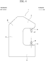
Fig. 4 shows an example of a conventional structure of a press apparatus having such a C-shaped frame structure. - A
press apparatus 1 shown inFig. 4 includes a C-shaped frame 2, a fixeddie 3 and amovable die 4. - The C-
shaped frame 2 is configured by combining alower frame 5, anintermediate frame 6 and anupper frame 7 in a C shape in which a front side in a forward and rearward direction and both sides in a leftward and rightward direction are open. - Further, among "a forward and rearward direction," "a leftward and rightward direction" and "an upward and downward direction," which are perpendicular to each other in the press apparatus, "the forward and rearward direction" is a leftward and rightward direction in the drawings, "the leftward and rightward direction" is a direction perpendicular to surfaces of the drawings, i.e., a front and back sides of the drawings, and "the upward and downward direction" is an upward and downward direction in the drawings. In addition, "a front side" of "the forward and rearward direction" is a right side in the drawings, and "a rear side" of "the forward and rearward direction" is a left side in the drawings.
- The
fixed die 3 is supported by and fixed to an upper surface of thelower frame 5. - The
movable die 4 is supported movably with respect to theupper frame 7 in the upward and downward direction while being disposed above thefixed die 3. For this reason, specifically, themovable die 4 is supported movably in the upward and downward direction by a hydraulic or electrically-operated cylinder (not shown) assembled on theupper frame 7. - When pressing of a workpiece is performed using the
press apparatus 1 having the above-mentioned configuration, for example, in a state in which themovable die 4 is retracted upward from thefixed die 3 and the workpiece is set on thefixed die 3 or themovable die 4, themovable die 4 is moved downward toward thefixed die 3. Accordingly, predetermined pressing such as shearing, bending, drawing, forging, or the like, is performed on the workpiece between thefixed die 3 and themovable die 4. - [Patent Literature 1]
Japanese Unexamined Patent Application, First Publication No.2001-25900 - Incidentally, when pressing of the workpiece is performed using the
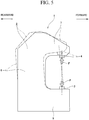
press apparatus 1 in this way, a processing reaction force F from the workpiece is applied to the C-shaped frame 2 via thefixed die 3 and the movable die 4 (and the cylinder). Accordingly, elastic deformation that is referred to as opening shown by an alternating two dots-dash line inFig. 5 occurs in the C-shaped frame 2. Then, accordingly, axis displacement that is referred to as relative displacement between thefixed die 3 and themovable die 4 in the forward and rearward direction or inclination of central axes of thefixed die 3 and themovable die 4 occurs between thefixed die 3 and themovable die 4. For this reason, it is difficult to secure processing accuracy of the workpiece unless some countermeasures are taken against the elastic deformation of the opening of the C-shaped frame 2 as described above. - Here, in the related art, in order to minimize the elastic deformation of the opening of the C-shaped frame as described above, a countermeasure of increasing a thickness of the C-shaped frame and increasing rigidity thereof was taken.
- However, in order to respond to a demand of miniaturization or cost reduction generally imposed on a mechanical apparatus, there is a certain limit on increasing the thickness of the C-shaped frame.
- Accordingly, it is difficult to respond to requirements for further improvement in processing accuracy of a workpiece by merely adopting this countermeasure.
- Meanwhile, as another countermeasure,
Patent Literature 1 discloses a structure in which a mechanism configured to prevent occurrence of axis displacement between a fixed die and a movable die even when elastic deformation of opening occurs in a C-shaped frame is incorporated. - However, when such a mechanism is incorporated, there is a problem in which complication or an increase in cost of the structure of the press apparatus may become significant.
- An aspect of the present invention is directed to providing a structure in which a C-shaped frame can be elastically deformed such that axis displacement occurring between a fixed die and a movable die is effectively minimized when pressing is performed on a workpiece between a fixed die and a movable die.
-
- (1) A frame structure of an aspect of the present invention includes a C-shaped frame having a front side that opens in a forward and rearward direction among the forward and rearward direction, a leftward and rightward direction and an upward and downward direction, which are perpendicular to each other; an upper action section supported by an upper front portion of the C-shaped frame; and a lower action section supported by a lower front portion of the C-shaped frame, wherein, when a reaction force is applied through the upper action section, the C-shaped frame is deformed such that a displacement of the upper action section in the forward and rearward direction, which occurs according to an elastic deformation of the C-shaped frame, is canceled out and such that a displacement of a pivotal movement about a leftward and rightward direction axis of the upper action section is canceled out.
- (2) In the aspect of (1), according to the elastic deformation, the C-shaped frame may have a portion that displaces the upper action section forward and a portion that displaces the upper action section rearward.
- (3) In addition, in the aspect of (1) or (2), according to the elastic deformation, the C-shaped frame may have a portion that pivots the upper action section to a one side about the leftward and rightward direction axis and a portion that pivots the upper action section to another side about the leftward and rightward direction axis.
- (4) A frame structure of another aspect of the present invention includes a C-shaped frame that includes: a lower frame, an intermediate frame having a lower end portion coupled to the lower frame, a first upper frame which has a rear end portion coupled to an upper end portion of the intermediate frame and in which a front end portion thereof is disposed below the rear end portion thereof, and a second upper frame having a front end portion coupled to the front end portion of the first upper frame; an upper action section supported by the second upper frame; and a lower action section supported by the lower frame.
- (5) In the aspect of (4), the lower action section may be supported movably with respect to the second upper frame in the upward and downward direction.
- (6) In the aspect of (4) or (5), a pressing process of a workpiece may be performed between the upper action section and the lower action section.
- (7) A processing apparatus of an aspect of the present invention includes the frame structure according to any one of the above-mentioned (1) to (6).
- (8) A method of manufacturing components of an aspect of the present invention uses the frame structure according to any one of the above-mentioned (1) to (6).
- (9) A method of manufacturing a rolling bearing of an aspect of the present invention uses the frame structure according to any one of the above-mentioned (1) to (6).
- (10) A method of manufacturing a vehicle of an aspect of the present invention uses the frame structure according to any one of the above-mentioned (1) to (6).
- (11) A method of manufacturing a machine of an aspect of the present invention uses the frame structure according to any one of the above-mentioned (1) to (6).
- (12) A press apparatus of another aspect of the present invention includes a first point of action and a second point of action, to which a reaction force upon pressing are applied; and a frame that includes a continuous element that is continuous between the first point of action and the second point of action, the continuous element having a gap formed between the first point of action and the second point of action in a first direction, wherein the continuous element has a first position, a second position and a third position in sequence from the first point of action toward the second point of action, the third position and the second point of action are disposed between the first position and the second position in the first direction, the second point of action is disposed between the second position and the third position in a second direction crossing the first direction, and an angle between a line that connects the second position and the third position and a line that connects the third position and the second point of action varies during an elastic deformation of the frame upon a pressing process.
- According to the press apparatus of the present invention, it is possible to electrically deform the C-shaped frame such that axis displacement occurring between a fixed die and a movable die is effectively minimized when pressing is performed on a workpiece between the fixed die and the movable die.
-
-
Fig. 1 is a schematic side view of a press apparatus according to a first embodiment of the present invention. -
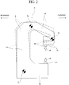
Fig. 2 is a schematic side view showing the press apparatus according to the first embodiment of the present invention in a state before and after a C-shaped frame is elastically deformed by a processing reaction force. -
Fig. 3 is a side view showing a skeleton model of the C-shaped frame according to the first embodiment of the present invention in a state before and after the C-shaped frame is elastically deformed by a processing reaction force. -
Fig. 4 is a schematic side view showing a press apparatus having a conventional structure. -
Fig. 5 is a schematic side view showing the press apparatus having a conventional structure in a state before and after a C-shaped frame is elastically deformed by a processing reaction force. - A first embodiment of the present invention will be described with reference to
Figs. 1 to 3 . - A
press apparatus 8 of the example is used while being placed on a floor surface of a factory or the like, and includes a C-shaped frame 9, a fixed die (an upper action section, a second point of action) 10 and a movable die (a lower action section, a first point of action) 11. - The C-
shaped frame 9 is configured by combining alower frame 12, anintermediate frame 13, a firstupper frame 14 and a secondupper frame 15, which are formed of a metal, in substantially a C shape in which a front side in the forward and rearward direction and both sides in the leftward and rightward direction are open. - Specifically, the
lower frame 12 is placed on a floor surface of a factory or the like, and disposed in the forward and rearward direction. In addition, theintermediate frame 13 is disposed in the upward and downward direction, and has a lower end portion that is coupled to a rear end portion of thelower frame 12. In addition, the firstupper frame 14 is disposed in the forward and rearward direction, and has a rear end portion that is coupled to an upper end portion of theintermediate frame 13 and a front end portion disposed below the rear end portion. In other words, the firstupper frame 14 is inclined from the rear end portion thereof in a direction in which it is located more downward as it goes closer to the front end portion thereof. - In addition, the second
upper frame 15 is disposed in the forward and rearward direction, and has a front end portion that is coupled to a front end portion of the firstupper frame 14. In the case of the example, a length of the secondupper frame 15 is sufficiently shorter than that of the firstupper frame 14. - Further, the above-mentioned C-
shaped frame 9 may be integrally formed as a whole, in addition to being able to be configured by coupling and fixing a plurality of parts to each other. - The
fixed die 10 is supported by and fixed to a lower surface of the rear end portion of the secondupper frame 15. - The
movable die 11 is supported movably with respect to the front end portion of thelower frame 12 in the upward and downward direction while being disposed below thefixed die 10. For this reason, specifically, themovable die 11 is supported movably in the upward and downward direction by a hydraulic or electrically-operated cylinder (not shown) assembled on thelower frame 12. In addition, in this state, central axes of the fixeddie 10 and themovable die 11 are disposed on the same virtual line extending in a vertical direction. - When pressing of the workpiece is performed using the
press apparatus 8 of the example having the above-mentioned configuration, for example, themovable die 11 is moved upward toward the fixed die 10 in a state in which themovable die 11 is retracted downward from the fixeddie 10 and the workpiece is set on the fixed die 10 or themovable die 11. Accordingly, predetermined pressing such as shearing, bending, drawing, forging, or the like, is performed with respect to the workpiece between the fixeddie 10 and themovable die 11. - When pressing of the workpiece is performed using the
press apparatus 8 as described above, the processing reaction force F from the workpiece is applied to the C-shapedframe 9 via the fixeddie 10 and the movable die 11 (and the cylinder). Accordingly, for example, elastic deformation of opening as shown by a two-dot chain line inFig. 2 occurs in the C-shapedframe 9. - Specifically, in
Fig. 2 , the C-shapedframe 9 is elastically deformed such that theintermediate frame 13 is pivoted, i.e., tilted counterclockwise (a + direction) to one side about an axis Z1 in the leftward and rightward direction with respect to thelower frame 12, the firstupper frame 14 is pivoted, i.e., tilted counterclockwise (the + direction) about an axis Z2 in the leftward and rightward direction with respect to theintermediate frame 13, and the secondupper frame 15 is pivoted, i.e., tilted clockwise (a - direction) to the other side about an axis Z3 in the leftward and rightward direction with respect to the firstupper frame 14. Further, since the processing reaction force F applied to thelower frame 12 is supported by the floor surface, an attitude of thelower frame 12 does not vary. -
Fig. 3 schematically shows a variation in attitude of the C-shapedframe 9 at this time, i.e., shows a skeleton model in which elastic bending deformation occurring in each of theframes 13 to 15 is ignored. Also inFig. 3 , likeFig. 2 , the C-shapedframe 9 in a state before elastic deformation is shown by a solid line and the C-shapedframe 9 in a state after elastic deformation is shown by a two-dot chain line. - The
frame 9 has a first point of action (11) corresponding to the movable die (the lower action section) 11, a second point of action (10) corresponding to the fixed die (the upper action section) 10. The first point of action (11) and the second point of action (10) are disposed to face each other, and a reaction force upon processing (for example, pressing) is substantially simultaneously applied to the first point of action (11) and the second point of action (10). In at least a first direction (for example, in the upward and downward direction), a gap is formed between the first point of action (11) and the second point of action (10). Theframe 9 has a continuous element that continues between the first point of action (11) and the second point of action (10), and the continuous element extends at least the first direction and a second direction (for example, the upward and downward direction) crossing the first direction. The continuous element has a first element (12) corresponding to thelower frame 12, a second element (13) corresponding to theintermediate frame 13, a third element (14) corresponding to theupper frame 14, and a fourth element (15) corresponding to theupper frame 15. The continuous element of theframe 9 has a first position Z1, a second position Z2 and a third position Z3 in sequence from the first point of action (11) toward the second point of action (10). In the continuous element of theframe 9, the first position Z1 is disposed between the first element (12) and the second element (13). The second position Z2 is disposed between the second element (13) and the third element (14). The third position Z3 is disposed between the third element (14) and the fourth element (15). In other words, in the continuous element of theframe 9, the first element (12) is disposed between the first point of action (11) and the first position Z1, the second element (13) is disposed between the first position Z1 and the second position Z2, the third element (14) is disposed between the second position Z2 and the third position Z3, and the fourth element (15) is disposed between the third position Z3 and the second point of action (10). In the first direction, the third position Z3 and the second point of action (10) are disposed between the first position Z1 and the second position Z2. In the second direction crossing the first direction, the second point of action (10) is disposed between the second position Z2 and the third position Z3. In an example, the second position Z2, the third position Z3 and the second point of action (10) are disposed above the first point of action (11) and the first position Z1. The second position Z2 is disposed above the third position Z3 and the second point of action (10). In the forward and rearward direction, the second point of action (10) is disposed between the second position Z2 and the third position Z3. In the entire elastic deformation of theframe 9 upon processing (for example, pressing), an angle (γ) between a line that connects the second position Z2 and the third position Z3 and a line that connects the third position Z3 and the second point of action (11) varies (γ1→γ2). - As shown in
Fig. 3 , when theintermediate frame 13 is tilted counterclockwise (the + direction) with respect to thelower frame 12 by the processing reaction force F, a narrow angle between thelower frame 12 and theintermediate frame 13 varies from α1 to α2, i.e., increased by α2-α1. In addition, when the firstupper frame 14 is similarly tilted counterclockwise (the + direction) with respect to theintermediate frame 13, a narrow angle between theintermediate frame 13 and the firstupper frame 14 varies from β1 to β2, i.e., increased by β2-β1. In addition, when the secondupper frame 15 is similarly tilted clockwise (the - direction) with respect to the firstupper frame 14, a narrow angle between the firstupper frame 14 and the secondupper frame 15 varies from γ1 to γ2, i.e., reduced by γ1-γ2. - In addition, in the case of an example, when the
intermediate frame 13 is tilted counterclockwise (the + direction) with respect to thelower frame 12 as described above, a central axis of the fixeddie 10 is also tilted counterclockwise (the + direction) by the same angle (α2-α1). In addition, when the firstupper frame 14 is tilted counterclockwise (the + direction) with respect to theintermediate frame 13 as described above, a central axis of the fixeddie 10 is also tilted counterclockwise (the + direction) by the same angle (β2-β1). In addition, when the secondupper frame 15 is tilted clockwise (the - direction) with respect to the firstupper frame 14 as described above, a central axis of the fixeddie 10 is also tilted clockwise (the - direction) by the same angle (γ1-γ2). - That is, in the case of the example, since a counterclockwise (the + direction) tilting angle {(α2-α1)+(β2-β1)} of the central axis of the fixed die 10 occurring due to the counterclockwise (the + direction) tilting of the
intermediate frame 13 and the firstupper frame 14 and a clockwise (the - direction) tilting angle (γ1-γ2) of the central axis of the fixed die 10 occurring due to the clockwise (the - direction) tilting of the secondupper frame 15 have substantially the same size and invert signs, the angles act to cancel each other. For this reason, in the case of the example, inclination of the central axes of the fixeddie 10 and themovable die 11 occurring when the pressing is performed on the workpiece is effectively inhibited. - In addition, in the case of the example, when the
intermediate frame 13 is tilted counterclockwise (the + direction) with respect to thelower frame 12 as described above, the upper end portion of theintermediate frame 13 is displaced rearward by a distance {L1sin(α2-α1)} in accordance with a length {L1 (Fig. 3 )} and a tilting angle (α2-α1) of theintermediate frame 13 in the forward and rearward direction. Then, accordingly, the fixeddie 10 is also displaced rearward by the same distance. - In addition, in the case of the example, since the front end portion of the first
upper frame 14 is disposed below the rear end portion thereof, when the firstupper frame 14 is tilted counterclockwise (the + direction) with respect to theintermediate frame 13 as described above, the front end portion of the firstupper frame 14 is displaced forward by a distance [L2{cos(π-α2-β2)-cos(π-α1-β1)} {≒L2(cosγ2-cosγ1)}] in accordance with a length {L2 (Fig. 3 )}, a tilting angle (β2-β1), and so on, of the firstupper frame 14 in the forward and rearward direction. Then, accordingly, the fixeddie 10 is also displaced forward by the same distance. Further, in the case of the example, since the length of the secondupper frame 15 is sufficiently shorter than the length of the firstupper frame 14 and the secondupper frame 15 is disposed to be substantially parallel to the forward and rearward direction, even when the secondupper frame 15 is tilted clockwise (the - direction) with respect to the firstupper frame 14 as described above, the fixeddie 10 has an extremely small displacement in the forward and rearward direction. - That is, in the case of the example, since rearward displacement of the fixed die 10 occurring due to the counterclockwise (the + direction) tilting of the
intermediate frame 13 and forward displacement of the fixed die 10 occurring due to the counterclockwise (the + direction) tilting of the firstupper frame 14 have substantially the same size and invert signs, the displacements act to cancel each other. For this reason, in the case of the example, a relative displacement amount in the forward and rearward direction between the fixeddie 10 and themovable die 11 occurring when pressing is performed on the workpiece is effectively minimized. - As described above, in the case of the example, axis displacement (inclination of the central axes of the fixed
die 10 and themovable die 11, and relative displacement in the forward and rearward direction of the fixeddie 10 and the movable die 11) between the fixeddie 10 and themovable die 11 occurring when pressing is performed on the workpiece is effectively minimized. - For example, in the case of the example, when lengths or a balance between rigidities of parts that constitute the C-shaped
frame 9 are adjusted, as shown inFig. 2 , when pressing is performed on the workpiece, it is also possible to prevent almost entire axis displacement between the fixeddie 10 and themovable die 11. In other words, in the case of the example, according to an increase in elastic deformation amount of the C-shapedframe 9 due to an increase in processing reaction force, it is possible to prevent axis displacement between the fixeddie 10 and themovable die 11 while allowing upward displacement of the fixeddie 10. Accordingly, in the case of the example, improvement of processing accuracy of the workpiece and extension of lifespan of the fixeddie 10 and themovable die 11 can be achieved. - Further, in the above-mentioned embodiment, a configuration in which the
movable die 11 is supported movably with respect to thelower frame 12 in the upward and downward direction while the fixeddie 10 is supported by and fixed to the secondupper frame 15 is employed. However, when the present invention is realized, a configuration in which the movable die is supported movably with respect to the second upper frame in the upward and downward direction while the fixed die is supported by the lower frame can also be employed. - In addition, the example in the above-mentioned embodiment has been described using the configuration in which the C-shaped
frame 9 and thepress apparatus 8 are installed in the upward and downward direction. However, the direction in which the C-shapedframe 9 and thepress apparatus 8 are installed is not limited to the upward and downward direction and the C-shapedframe 9 and thepress apparatus 8 may be installed in an arbitrary direction. - Further, the frame structure of the above-mentioned embodiment may be used in a processing apparatus including, for example, a frictional agitation joining apparatus disclosed in Japanese Unexamined Patent Application, First Publication No.
2014-18850 2014-101896 - In addition, for example, the frame structure of the above-mentioned embodiment may be used for manufacture of a vehicle, a machine, or the like. In particular, the frame structure of the above-mentioned embodiment may be used for manufacturing a vehicle or a machine including a rolling bearing. Further, in a vehicle, a machine, or the like, that is a manufacturing target, regardless of a type of power, a power for operating the vehicle, the machine, or the like, may be other than manpower, or may be manpower.
- When the present invention is performed, in the structure of the embodiment shown in
Fig. 1 , for example, a material of the C-shapedframe 9 may be SS400 (JIS G 3101, rolled steel for a general structure), a thickness dimension T in the leftward and rightward direction of the C-shapedframe 9 is 35 mm, a length dimension LA inFig. 1 of theintermediate frame 13 is 370 mm, a width dimension WA inFig. 1 of theintermediate frame 13 is 140 mm, a length dimension LB inFig. 1 of the firstupper frame 14 is 130 mm, a width dimension WB inFig. 1 of the firstupper frame 14 is 51 mm, a length dimension Lc inFig. 1 of the secondupper frame 15 is 70 mm, a width dimension Wc inFig. 1 of the secondupper frame 15 is 15 mm, and a pressing force (a processing reaction force F) applied to the workpiece may be, for example, 4000 N. - Further, the material and the thickness dimension T in the leftward and rightward direction of the C-shaped
frame 9 is independent from the axis displacement between the fixeddie 10 and themovable die 11 occurring when a pressing force is applied to a workpiece, however, they influence a relative displacement amount in an axial direction (a pressing force direction) between the fixeddie 10 and themovable die 11 when a pressing force is applied to a workpiece. - When the above-mentioned configuration is employed, axis displacement between the fixed
die 10 and themovable die 11 occurring when a pressing force of, for example, 4000 N is applied to a workpiece is extremely small, specifically, ignorable in general pressing. -
- 1 Press apparatus
- 2 C-shaped frame
- 3 Fixed die
- 4 Movable die
- 5 Lower frame
- 6 Intermediate frame
- 7 Upper frame
- 8 Press apparatus
- 9 C-shaped frame
- 10 Fixed die
- 11 Movable die
- 12 Lower frame
- 13 Intermediate frame
- 14 First upper frame
- 15 Second upper frame
Claims (12)
- A frame structure comprising:a C-shaped frame having a front side that opens in a forward and rearward direction among the forward and rearward direction, a leftward and rightward direction and an upward and downward direction, which are perpendicular to each other;an upper action section supported by an upper front portion of the C-shaped frame; anda lower action section supported by a lower front portion of the C-shaped frame,wherein, when a reaction force is applied through the upper action section, the C-shaped frame is deformed such that a displacement of the upper action section in the forward and rearward direction, which occurs according to an elastic deformation of the C-shaped frame, is canceled out and such that a displacement of a pivotal movement about a leftward and rightward direction axis of the upper action section is canceled out.
- The frame structure according to claim 1, wherein, according to the elastic deformation, the C-shaped frame has a portion that displaces the upper action section forward and a portion that displaces the upper action section rearward.
- The frame structure according to claim 1 or 2, wherein, according to the elastic deformation, the C-shaped frame has a portion that pivots the upper action section to a one side about the leftward and rightward direction axis and a portion that pivots the upper action section to another side about the leftward and rightward direction axis.
- A frame structure comprising:a C-shaped frame that includes: a lower frame, an intermediate frame having a lower end portion coupled to the lower frame, a first upper frame which has a rear end portion coupled to an upper end portion of the intermediate frame and in which a front end portion thereof is disposed below the rear end portion thereof, and a second upper frame having a front end portion coupled to the front end portion of the first upper frame;an upper action section supported by the second upper frame; anda lower action section supported by the lower frame.
- The frame structure according to claim 4, wherein the lower action section is supported movably with respect to the second upper frame in the upward and downward direction.
- The frame structure according to claim 4 or 5, wherein a pressing process of a workpiece is performed between the upper action section and the lower action section.
- A processing apparatus including the frame structure according to any one of claims 1 to 6.
- A method of manufacturing components using the frame structure according to any one of claims 1 to 6.
- A method of manufacturing a rolling bearing using the frame structure according to any one of claims 1 to 6.
- A method of manufacturing a vehicle using the frame structure according to any one of claims 1 to 6.
- A method of manufacturing a machine using the frame structure according to any one of claims 1 to 6.
- A press apparatus comprising:a first point of action and a second point of action, to which a reaction force upon pressing are applied; anda frame that includes a continuous element that is continuous between the first point of action and the second point of action, the continuous element having a gap formed between the first point of action and the second point of action in a first direction,wherein the continuous element has a first position, a second position and a third position in sequence from the first point of action toward the second point of action,the third position and the second point of action are disposed between the first position and the second position in the first direction,the second point of action is disposed between the second position and the third position in a second direction crossing the first direction, andan angle between a line that connects the second position and the third position and a line that connects the third position and the second point of action varies during an elastic deformation of the frame upon a pressing process.
Applications Claiming Priority (2)
| Application Number | Priority Date | Filing Date | Title |
|---|---|---|---|
| JP2017019364 | 2017-02-06 | ||
| PCT/JP2017/031129 WO2018142654A1 (en) | 2017-02-06 | 2017-08-30 | Frame structure, machining device, method for producing component, method for producing rolling bearing, method for producing vehicle, method for producing machine, and press machine |
Publications (3)
| Publication Number | Publication Date |
|---|---|
| EP3578351A1 true EP3578351A1 (en) | 2019-12-11 |
| EP3578351A4 EP3578351A4 (en) | 2020-12-16 |
| EP3578351B1 EP3578351B1 (en) | 2024-02-28 |
Family
ID=63039588
Family Applications (1)
| Application Number | Title | Priority Date | Filing Date |
|---|---|---|---|
| EP17895047.3A Active EP3578351B1 (en) | 2017-02-06 | 2017-08-30 | Frame structure, method for producing component, method for producing rolling bearing, method for producing vehicle and method for producing machine |
Country Status (5)
| Country | Link |
|---|---|
| US (1) | US10611114B2 (en) |
| EP (1) | EP3578351B1 (en) |
| JP (2) | JP6380708B1 (en) |
| CN (1) | CN110198831B (en) |
| WO (1) | WO2018142654A1 (en) |
Families Citing this family (1)
| Publication number | Priority date | Publication date | Assignee | Title |
|---|---|---|---|---|
| EP4074432A1 (en) * | 2021-04-15 | 2022-10-19 | Bystronic Laser AG | Bending machine for bending workpieces, in particular bending press |
Family Cites Families (20)
| Publication number | Priority date | Publication date | Assignee | Title |
|---|---|---|---|---|
| FR528452A (en) * | 1920-06-04 | 1921-11-12 | Pierre Plana | Advanced gooseneck presses |
| JPS5095869A (en) * | 1973-12-27 | 1975-07-30 | ||
| JPS5916800U (en) * | 1982-07-20 | 1984-02-01 | 株式会社小松製作所 | press machine |
| SU1224181A1 (en) * | 1984-10-05 | 1986-04-15 | Предприятие П/Я А-7555 | Vertical press |
| JPS61154798A (en) * | 1984-12-28 | 1986-07-14 | Koshin Giken:Kk | Cantilver press device |
| JPS6233100A (en) * | 1986-04-05 | 1987-02-13 | Aida Eng Ltd | Construction of gap frame press |
| NL8801799A (en) * | 1988-07-14 | 1990-02-01 | Brouwer & Co Holding | TOOL MACHINE WITH C-SHAPED FRAME. |
| JP2894503B2 (en) * | 1990-02-28 | 1999-05-24 | 株式会社アマダ | Punch press |
| US5062290A (en) * | 1990-06-25 | 1991-11-05 | Burndy Corporation | Hydraulic crimping press for electrical connectors |
| DE19501469C2 (en) * | 1995-01-19 | 1998-03-26 | Hemscheidt Maschtech Schwerin | Tie bar-less form locking device |
| US5633024A (en) * | 1995-12-07 | 1997-05-27 | Ziv-Av; Amir | Clamping assembly for injection molding apparatus |
| US6072583A (en) * | 1996-12-06 | 2000-06-06 | General Electro Mechanical Corp. | Apparatus and method for detecting mis-oriented fasteners |
| JP2001025900A (en) | 1999-07-12 | 2001-01-30 | Aida Eng Ltd | Gib block correction device of c-frame press |
| EP1401593B1 (en) * | 2001-03-16 | 2005-06-08 | Bystronic Laser AG | Method for setting the travel of a press brake |
| US7305755B2 (en) * | 2003-12-18 | 2007-12-11 | Heiko Schmidt | Processing tong |
| DE102005043211A1 (en) * | 2005-09-09 | 2007-03-15 | Newfrey Llc, Newark | Joining device for forming joining |
| JP2014018850A (en) | 2012-07-23 | 2014-02-03 | Nsk Ltd | Friction stir joining device |
| JP2014101896A (en) | 2012-11-16 | 2014-06-05 | Nsk Ltd | Rolling bearing |
| JP6237100B2 (en) * | 2013-10-17 | 2017-11-29 | 日本精工株式会社 | Manufacturing method of wheel bearing rolling bearing unit |
| JP2017019364A (en) | 2015-07-09 | 2017-01-26 | 本田技研工業株式会社 | Vehicular seat assembly |
-
2017
- 2017-08-30 JP JP2018512228A patent/JP6380708B1/en active Active
- 2017-08-30 EP EP17895047.3A patent/EP3578351B1/en active Active
- 2017-08-30 US US16/087,927 patent/US10611114B2/en active Active
- 2017-08-30 CN CN201780084209.2A patent/CN110198831B/en active Active
- 2017-08-30 WO PCT/JP2017/031129 patent/WO2018142654A1/en not_active Ceased
-
2018
- 2018-07-20 JP JP2018136270A patent/JP7020327B2/en active Active
Also Published As
| Publication number | Publication date |
|---|---|
| EP3578351A4 (en) | 2020-12-16 |
| EP3578351B1 (en) | 2024-02-28 |
| US10611114B2 (en) | 2020-04-07 |
| US20190084263A1 (en) | 2019-03-21 |
| CN110198831B (en) | 2022-02-22 |
| JP6380708B1 (en) | 2018-08-29 |
| CN110198831A (en) | 2019-09-03 |
| JP7020327B2 (en) | 2022-02-16 |
| JPWO2018142654A1 (en) | 2019-02-14 |
| WO2018142654A1 (en) | 2018-08-09 |
| JP2018158387A (en) | 2018-10-11 |
Similar Documents
| Publication | Publication Date | Title |
|---|---|---|
| CN105916625B (en) | Install components | |
| US20140283576A1 (en) | Sheet material processing apparatus, press die, and die setting body | |
| KR102409136B1 (en) | Manufacturing method of thickness-varied metal plate, manufacturing method of pressed part, and processing machine | |
| US10399520B2 (en) | Vehicle body structure | |
| EP0983808B1 (en) | Cam slide driving apparatus | |
| KR101649811B1 (en) | Balustrade device for conveyor | |
| EP3578351B1 (en) | Frame structure, method for producing component, method for producing rolling bearing, method for producing vehicle and method for producing machine | |
| US10259297B2 (en) | Vehicle door frame | |
| US20210291247A1 (en) | Bending method | |
| TWI461247B (en) | Bending machine for bending plates | |
| US8783084B2 (en) | Supply station | |
| US6253591B1 (en) | Method and apparatus for bending a metallic flanged member | |
| EP2682200B1 (en) | Load applying device, press-molding die, press-molding method | |
| JP2019025529A (en) | Roller hemming processing method | |
| EP3756778B1 (en) | Crowning method for press brake, and press brake | |
| US11806774B2 (en) | Punch tool with expanded portion and method of operating the same | |
| CN114669616A (en) | Structural member | |
| US6849820B2 (en) | Preliminary assembly system and assembly method for vehicle body component parts | |
| Abratis et al. | Air bending process for load optimised profiles | |
| JPH0337479B2 (en) | ||
| JP4944271B1 (en) | monkey wrench | |
| CN113751551A (en) | a bending equipment | |
| CA2988475A1 (en) | Manufacturing method of thickness-varied metal plate, manufacturing method of pressed part, and processing machine | |
| JP2020093667A (en) | Vehicle structure | |
| JP2001347321A (en) | Work positioning position |
Legal Events
| Date | Code | Title | Description |
|---|---|---|---|
| STAA | Information on the status of an ep patent application or granted ep patent |
Free format text: STATUS: THE INTERNATIONAL PUBLICATION HAS BEEN MADE |
|
| PUAI | Public reference made under article 153(3) epc to a published international application that has entered the european phase |
Free format text: ORIGINAL CODE: 0009012 |
|
| STAA | Information on the status of an ep patent application or granted ep patent |
Free format text: STATUS: REQUEST FOR EXAMINATION WAS MADE |
|
| 17P | Request for examination filed |
Effective date: 20190624 |
|
| AK | Designated contracting states |
Kind code of ref document: A1 Designated state(s): AL AT BE BG CH CY CZ DE DK EE ES FI FR GB GR HR HU IE IS IT LI LT LU LV MC MK MT NL NO PL PT RO RS SE SI SK SM TR |
|
| AX | Request for extension of the european patent |
Extension state: BA ME |
|
| DAV | Request for validation of the european patent (deleted) | ||
| DAX | Request for extension of the european patent (deleted) | ||
| A4 | Supplementary search report drawn up and despatched |
Effective date: 20201118 |
|
| RIC1 | Information provided on ipc code assigned before grant |
Ipc: B21D 5/02 20060101ALI20201112BHEP Ipc: B21J 13/04 20060101ALI20201112BHEP Ipc: B30B 15/04 20060101AFI20201112BHEP |
|
| STAA | Information on the status of an ep patent application or granted ep patent |
Free format text: STATUS: EXAMINATION IS IN PROGRESS |
|
| 17Q | First examination report despatched |
Effective date: 20221124 |
|
| GRAP | Despatch of communication of intention to grant a patent |
Free format text: ORIGINAL CODE: EPIDOSNIGR1 |
|
| STAA | Information on the status of an ep patent application or granted ep patent |
Free format text: STATUS: GRANT OF PATENT IS INTENDED |
|
| INTG | Intention to grant announced |
Effective date: 20231010 |
|
| GRAS | Grant fee paid |
Free format text: ORIGINAL CODE: EPIDOSNIGR3 |
|
| GRAA | (expected) grant |
Free format text: ORIGINAL CODE: 0009210 |
|
| STAA | Information on the status of an ep patent application or granted ep patent |
Free format text: STATUS: THE PATENT HAS BEEN GRANTED |
|
| AK | Designated contracting states |
Kind code of ref document: B1 Designated state(s): AL AT BE BG CH CY CZ DE DK EE ES FI FR GB GR HR HU IE IS IT LI LT LU LV MC MK MT NL NO PL PT RO RS SE SI SK SM TR |
|
| REG | Reference to a national code |
Ref country code: GB Ref legal event code: FG4D |
|
| REG | Reference to a national code |
Ref country code: CH Ref legal event code: EP |
|
| REG | Reference to a national code |
Ref country code: DE Ref legal event code: R096 Ref document number: 602017079642 Country of ref document: DE |
|
| REG | Reference to a national code |
Ref country code: IE Ref legal event code: FG4D |
|
| REG | Reference to a national code |
Ref country code: LT Ref legal event code: MG9D |
|
| PG25 | Lapsed in a contracting state [announced via postgrant information from national office to epo] |
Ref country code: IS Free format text: LAPSE BECAUSE OF FAILURE TO SUBMIT A TRANSLATION OF THE DESCRIPTION OR TO PAY THE FEE WITHIN THE PRESCRIBED TIME-LIMIT Effective date: 20240628 |
|
| REG | Reference to a national code |
Ref country code: NL Ref legal event code: MP Effective date: 20240228 |
|
| PG25 | Lapsed in a contracting state [announced via postgrant information from national office to epo] |
Ref country code: LT Free format text: LAPSE BECAUSE OF FAILURE TO SUBMIT A TRANSLATION OF THE DESCRIPTION OR TO PAY THE FEE WITHIN THE PRESCRIBED TIME-LIMIT Effective date: 20240228 |
|
| PG25 | Lapsed in a contracting state [announced via postgrant information from national office to epo] |
Ref country code: GR Free format text: LAPSE BECAUSE OF FAILURE TO SUBMIT A TRANSLATION OF THE DESCRIPTION OR TO PAY THE FEE WITHIN THE PRESCRIBED TIME-LIMIT Effective date: 20240529 |
|
| PG25 | Lapsed in a contracting state [announced via postgrant information from national office to epo] |
Ref country code: NL Free format text: LAPSE BECAUSE OF FAILURE TO SUBMIT A TRANSLATION OF THE DESCRIPTION OR TO PAY THE FEE WITHIN THE PRESCRIBED TIME-LIMIT Effective date: 20240228 Ref country code: RS Free format text: LAPSE BECAUSE OF FAILURE TO SUBMIT A TRANSLATION OF THE DESCRIPTION OR TO PAY THE FEE WITHIN THE PRESCRIBED TIME-LIMIT Effective date: 20240528 Ref country code: HR Free format text: LAPSE BECAUSE OF FAILURE TO SUBMIT A TRANSLATION OF THE DESCRIPTION OR TO PAY THE FEE WITHIN THE PRESCRIBED TIME-LIMIT Effective date: 20240228 |
|
| PG25 | Lapsed in a contracting state [announced via postgrant information from national office to epo] |
Ref country code: ES Free format text: LAPSE BECAUSE OF FAILURE TO SUBMIT A TRANSLATION OF THE DESCRIPTION OR TO PAY THE FEE WITHIN THE PRESCRIBED TIME-LIMIT Effective date: 20240228 |
|
| PG25 | Lapsed in a contracting state [announced via postgrant information from national office to epo] |
Ref country code: RS Free format text: LAPSE BECAUSE OF FAILURE TO SUBMIT A TRANSLATION OF THE DESCRIPTION OR TO PAY THE FEE WITHIN THE PRESCRIBED TIME-LIMIT Effective date: 20240528 Ref country code: NO Free format text: LAPSE BECAUSE OF FAILURE TO SUBMIT A TRANSLATION OF THE DESCRIPTION OR TO PAY THE FEE WITHIN THE PRESCRIBED TIME-LIMIT Effective date: 20240528 Ref country code: NL Free format text: LAPSE BECAUSE OF FAILURE TO SUBMIT A TRANSLATION OF THE DESCRIPTION OR TO PAY THE FEE WITHIN THE PRESCRIBED TIME-LIMIT Effective date: 20240228 Ref country code: LT Free format text: LAPSE BECAUSE OF FAILURE TO SUBMIT A TRANSLATION OF THE DESCRIPTION OR TO PAY THE FEE WITHIN THE PRESCRIBED TIME-LIMIT Effective date: 20240228 Ref country code: IS Free format text: LAPSE BECAUSE OF FAILURE TO SUBMIT A TRANSLATION OF THE DESCRIPTION OR TO PAY THE FEE WITHIN THE PRESCRIBED TIME-LIMIT Effective date: 20240628 Ref country code: HR Free format text: LAPSE BECAUSE OF FAILURE TO SUBMIT A TRANSLATION OF THE DESCRIPTION OR TO PAY THE FEE WITHIN THE PRESCRIBED TIME-LIMIT Effective date: 20240228 Ref country code: GR Free format text: LAPSE BECAUSE OF FAILURE TO SUBMIT A TRANSLATION OF THE DESCRIPTION OR TO PAY THE FEE WITHIN THE PRESCRIBED TIME-LIMIT Effective date: 20240529 Ref country code: FI Free format text: LAPSE BECAUSE OF FAILURE TO SUBMIT A TRANSLATION OF THE DESCRIPTION OR TO PAY THE FEE WITHIN THE PRESCRIBED TIME-LIMIT Effective date: 20240228 Ref country code: ES Free format text: LAPSE BECAUSE OF FAILURE TO SUBMIT A TRANSLATION OF THE DESCRIPTION OR TO PAY THE FEE WITHIN THE PRESCRIBED TIME-LIMIT Effective date: 20240228 Ref country code: BG Free format text: LAPSE BECAUSE OF FAILURE TO SUBMIT A TRANSLATION OF THE DESCRIPTION OR TO PAY THE FEE WITHIN THE PRESCRIBED TIME-LIMIT Effective date: 20240228 |
|
| PG25 | Lapsed in a contracting state [announced via postgrant information from national office to epo] |
Ref country code: PL Free format text: LAPSE BECAUSE OF FAILURE TO SUBMIT A TRANSLATION OF THE DESCRIPTION OR TO PAY THE FEE WITHIN THE PRESCRIBED TIME-LIMIT Effective date: 20240228 Ref country code: PT Free format text: LAPSE BECAUSE OF FAILURE TO SUBMIT A TRANSLATION OF THE DESCRIPTION OR TO PAY THE FEE WITHIN THE PRESCRIBED TIME-LIMIT Effective date: 20240628 |
|
| REG | Reference to a national code |
Ref country code: AT Ref legal event code: MK05 Ref document number: 1660894 Country of ref document: AT Kind code of ref document: T Effective date: 20240228 |
|
| PG25 | Lapsed in a contracting state [announced via postgrant information from national office to epo] |
Ref country code: SE Free format text: LAPSE BECAUSE OF FAILURE TO SUBMIT A TRANSLATION OF THE DESCRIPTION OR TO PAY THE FEE WITHIN THE PRESCRIBED TIME-LIMIT Effective date: 20240228 Ref country code: PT Free format text: LAPSE BECAUSE OF FAILURE TO SUBMIT A TRANSLATION OF THE DESCRIPTION OR TO PAY THE FEE WITHIN THE PRESCRIBED TIME-LIMIT Effective date: 20240628 Ref country code: PL Free format text: LAPSE BECAUSE OF FAILURE TO SUBMIT A TRANSLATION OF THE DESCRIPTION OR TO PAY THE FEE WITHIN THE PRESCRIBED TIME-LIMIT Effective date: 20240228 Ref country code: LV Free format text: LAPSE BECAUSE OF FAILURE TO SUBMIT A TRANSLATION OF THE DESCRIPTION OR TO PAY THE FEE WITHIN THE PRESCRIBED TIME-LIMIT Effective date: 20240228 |
|
| PG25 | Lapsed in a contracting state [announced via postgrant information from national office to epo] |
Ref country code: DK Free format text: LAPSE BECAUSE OF FAILURE TO SUBMIT A TRANSLATION OF THE DESCRIPTION OR TO PAY THE FEE WITHIN THE PRESCRIBED TIME-LIMIT Effective date: 20240228 |
|
| PG25 | Lapsed in a contracting state [announced via postgrant information from national office to epo] |
Ref country code: SM Free format text: LAPSE BECAUSE OF FAILURE TO SUBMIT A TRANSLATION OF THE DESCRIPTION OR TO PAY THE FEE WITHIN THE PRESCRIBED TIME-LIMIT Effective date: 20240228 |
|
| PG25 | Lapsed in a contracting state [announced via postgrant information from national office to epo] |
Ref country code: CZ Free format text: LAPSE BECAUSE OF FAILURE TO SUBMIT A TRANSLATION OF THE DESCRIPTION OR TO PAY THE FEE WITHIN THE PRESCRIBED TIME-LIMIT Effective date: 20240228 Ref country code: EE Free format text: LAPSE BECAUSE OF FAILURE TO SUBMIT A TRANSLATION OF THE DESCRIPTION OR TO PAY THE FEE WITHIN THE PRESCRIBED TIME-LIMIT Effective date: 20240228 |
|
| PG25 | Lapsed in a contracting state [announced via postgrant information from national office to epo] |
Ref country code: AT Free format text: LAPSE BECAUSE OF FAILURE TO SUBMIT A TRANSLATION OF THE DESCRIPTION OR TO PAY THE FEE WITHIN THE PRESCRIBED TIME-LIMIT Effective date: 20240228 |
|
| PG25 | Lapsed in a contracting state [announced via postgrant information from national office to epo] |
Ref country code: SK Free format text: LAPSE BECAUSE OF FAILURE TO SUBMIT A TRANSLATION OF THE DESCRIPTION OR TO PAY THE FEE WITHIN THE PRESCRIBED TIME-LIMIT Effective date: 20240228 |
|
| PG25 | Lapsed in a contracting state [announced via postgrant information from national office to epo] |
Ref country code: SM Free format text: LAPSE BECAUSE OF FAILURE TO SUBMIT A TRANSLATION OF THE DESCRIPTION OR TO PAY THE FEE WITHIN THE PRESCRIBED TIME-LIMIT Effective date: 20240228 Ref country code: SK Free format text: LAPSE BECAUSE OF FAILURE TO SUBMIT A TRANSLATION OF THE DESCRIPTION OR TO PAY THE FEE WITHIN THE PRESCRIBED TIME-LIMIT Effective date: 20240228 Ref country code: RO Free format text: LAPSE BECAUSE OF FAILURE TO SUBMIT A TRANSLATION OF THE DESCRIPTION OR TO PAY THE FEE WITHIN THE PRESCRIBED TIME-LIMIT Effective date: 20240228 Ref country code: EE Free format text: LAPSE BECAUSE OF FAILURE TO SUBMIT A TRANSLATION OF THE DESCRIPTION OR TO PAY THE FEE WITHIN THE PRESCRIBED TIME-LIMIT Effective date: 20240228 Ref country code: DK Free format text: LAPSE BECAUSE OF FAILURE TO SUBMIT A TRANSLATION OF THE DESCRIPTION OR TO PAY THE FEE WITHIN THE PRESCRIBED TIME-LIMIT Effective date: 20240228 Ref country code: CZ Free format text: LAPSE BECAUSE OF FAILURE TO SUBMIT A TRANSLATION OF THE DESCRIPTION OR TO PAY THE FEE WITHIN THE PRESCRIBED TIME-LIMIT Effective date: 20240228 Ref country code: AT Free format text: LAPSE BECAUSE OF FAILURE TO SUBMIT A TRANSLATION OF THE DESCRIPTION OR TO PAY THE FEE WITHIN THE PRESCRIBED TIME-LIMIT Effective date: 20240228 |
|
| REG | Reference to a national code |
Ref country code: DE Ref legal event code: R097 Ref document number: 602017079642 Country of ref document: DE |
|
| PG25 | Lapsed in a contracting state [announced via postgrant information from national office to epo] |
Ref country code: IT Free format text: LAPSE BECAUSE OF FAILURE TO SUBMIT A TRANSLATION OF THE DESCRIPTION OR TO PAY THE FEE WITHIN THE PRESCRIBED TIME-LIMIT Effective date: 20240228 |
|
| PG25 | Lapsed in a contracting state [announced via postgrant information from national office to epo] |
Ref country code: IT Free format text: LAPSE BECAUSE OF FAILURE TO SUBMIT A TRANSLATION OF THE DESCRIPTION OR TO PAY THE FEE WITHIN THE PRESCRIBED TIME-LIMIT Effective date: 20240228 |
|
| PLBE | No opposition filed within time limit |
Free format text: ORIGINAL CODE: 0009261 |
|
| STAA | Information on the status of an ep patent application or granted ep patent |
Free format text: STATUS: NO OPPOSITION FILED WITHIN TIME LIMIT |
|
| 26N | No opposition filed |
Effective date: 20241129 |
|
| REG | Reference to a national code |
Ref country code: CH Ref legal event code: PL |
|
| PG25 | Lapsed in a contracting state [announced via postgrant information from national office to epo] |
Ref country code: LU Free format text: LAPSE BECAUSE OF NON-PAYMENT OF DUE FEES Effective date: 20240830 |
|
| PG25 | Lapsed in a contracting state [announced via postgrant information from national office to epo] |
Ref country code: SI Free format text: LAPSE BECAUSE OF FAILURE TO SUBMIT A TRANSLATION OF THE DESCRIPTION OR TO PAY THE FEE WITHIN THE PRESCRIBED TIME-LIMIT Effective date: 20240228 Ref country code: MC Free format text: LAPSE BECAUSE OF FAILURE TO SUBMIT A TRANSLATION OF THE DESCRIPTION OR TO PAY THE FEE WITHIN THE PRESCRIBED TIME-LIMIT Effective date: 20240228 Ref country code: CH Free format text: LAPSE BECAUSE OF NON-PAYMENT OF DUE FEES Effective date: 20240831 |
|
| REG | Reference to a national code |
Ref country code: BE Ref legal event code: MM Effective date: 20240831 |
|
| PG25 | Lapsed in a contracting state [announced via postgrant information from national office to epo] |
Ref country code: BE Free format text: LAPSE BECAUSE OF NON-PAYMENT OF DUE FEES Effective date: 20240831 |
|
| PG25 | Lapsed in a contracting state [announced via postgrant information from national office to epo] |
Ref country code: IE Free format text: LAPSE BECAUSE OF NON-PAYMENT OF DUE FEES Effective date: 20240830 |
|
| PGFP | Annual fee paid to national office [announced via postgrant information from national office to epo] |
Ref country code: DE Payment date: 20250702 Year of fee payment: 9 |
|
| PGFP | Annual fee paid to national office [announced via postgrant information from national office to epo] |
Ref country code: GB Payment date: 20250703 Year of fee payment: 9 |
|
| PGFP | Annual fee paid to national office [announced via postgrant information from national office to epo] |
Ref country code: FR Payment date: 20250703 Year of fee payment: 9 |
|
| PG25 | Lapsed in a contracting state [announced via postgrant information from national office to epo] |
Ref country code: CY Free format text: LAPSE BECAUSE OF FAILURE TO SUBMIT A TRANSLATION OF THE DESCRIPTION OR TO PAY THE FEE WITHIN THE PRESCRIBED TIME-LIMIT; INVALID AB INITIO Effective date: 20170830 |
|
| PG25 | Lapsed in a contracting state [announced via postgrant information from national office to epo] |
Ref country code: HU Free format text: LAPSE BECAUSE OF FAILURE TO SUBMIT A TRANSLATION OF THE DESCRIPTION OR TO PAY THE FEE WITHIN THE PRESCRIBED TIME-LIMIT; INVALID AB INITIO Effective date: 20170830 |