EP2682200B1 - Load applying device, press-molding die, press-molding method - Google Patents
Load applying device, press-molding die, press-molding method Download PDFInfo
- Publication number
- EP2682200B1 EP2682200B1 EP12752433.8A EP12752433A EP2682200B1 EP 2682200 B1 EP2682200 B1 EP 2682200B1 EP 12752433 A EP12752433 A EP 12752433A EP 2682200 B1 EP2682200 B1 EP 2682200B1
- Authority
- EP
- European Patent Office
- Prior art keywords
- load
- press
- plate
- die
- applying device
- Prior art date
- Legal status (The legal status is an assumption and is not a legal conclusion. Google has not performed a legal analysis and makes no representation as to the accuracy of the status listed.)
- Active
Links
- 238000000034 method Methods 0.000 title claims description 10
- 238000000465 moulding Methods 0.000 title 2
- 238000003475 lamination Methods 0.000 claims description 58
- 239000002184 metal Substances 0.000 claims description 22
- 230000000052 comparative effect Effects 0.000 description 7
- 229910000831 Steel Inorganic materials 0.000 description 4
- 230000000694 effects Effects 0.000 description 4
- 239000010959 steel Substances 0.000 description 4
- 239000010960 cold rolled steel Substances 0.000 description 3
- 230000036544 posture Effects 0.000 description 3
- 238000010030 laminating Methods 0.000 description 2
- OCKGFTQIICXDQW-ZEQRLZLVSA-N 5-[(1r)-1-hydroxy-2-[4-[(2r)-2-hydroxy-2-(4-methyl-1-oxo-3h-2-benzofuran-5-yl)ethyl]piperazin-1-yl]ethyl]-4-methyl-3h-2-benzofuran-1-one Chemical compound C1=C2C(=O)OCC2=C(C)C([C@@H](O)CN2CCN(CC2)C[C@H](O)C2=CC=C3C(=O)OCC3=C2C)=C1 OCKGFTQIICXDQW-ZEQRLZLVSA-N 0.000 description 1
- 208000033897 Systemic primary carnitine deficiency Diseases 0.000 description 1
- 238000000429 assembly Methods 0.000 description 1
- 238000012986 modification Methods 0.000 description 1
- 230000004048 modification Effects 0.000 description 1
- 238000012958 reprocessing Methods 0.000 description 1
- 208000016505 systemic primary carnitine deficiency disease Diseases 0.000 description 1
- 238000012795 verification Methods 0.000 description 1
- 238000003466 welding Methods 0.000 description 1
Images


Classifications
-
- B—PERFORMING OPERATIONS; TRANSPORTING
- B21—MECHANICAL METAL-WORKING WITHOUT ESSENTIALLY REMOVING MATERIAL; PUNCHING METAL
- B21D—WORKING OR PROCESSING OF SHEET METAL OR METAL TUBES, RODS OR PROFILES WITHOUT ESSENTIALLY REMOVING MATERIAL; PUNCHING METAL
- B21D22/00—Shaping without cutting, by stamping, spinning, or deep-drawing
- B21D22/02—Stamping using rigid devices or tools
-
- B—PERFORMING OPERATIONS; TRANSPORTING
- B21—MECHANICAL METAL-WORKING WITHOUT ESSENTIALLY REMOVING MATERIAL; PUNCHING METAL
- B21D—WORKING OR PROCESSING OF SHEET METAL OR METAL TUBES, RODS OR PROFILES WITHOUT ESSENTIALLY REMOVING MATERIAL; PUNCHING METAL
- B21D24/00—Special deep-drawing arrangements in, or in connection with, presses
- B21D24/02—Die-cushions
-
- B—PERFORMING OPERATIONS; TRANSPORTING
- B21—MECHANICAL METAL-WORKING WITHOUT ESSENTIALLY REMOVING MATERIAL; PUNCHING METAL
- B21D—WORKING OR PROCESSING OF SHEET METAL OR METAL TUBES, RODS OR PROFILES WITHOUT ESSENTIALLY REMOVING MATERIAL; PUNCHING METAL
- B21D22/00—Shaping without cutting, by stamping, spinning, or deep-drawing
- B21D22/20—Deep-drawing
- B21D22/22—Deep-drawing with devices for holding the edge of the blanks
-
- B—PERFORMING OPERATIONS; TRANSPORTING
- B21—MECHANICAL METAL-WORKING WITHOUT ESSENTIALLY REMOVING MATERIAL; PUNCHING METAL
- B21D—WORKING OR PROCESSING OF SHEET METAL OR METAL TUBES, RODS OR PROFILES WITHOUT ESSENTIALLY REMOVING MATERIAL; PUNCHING METAL
- B21D24/00—Special deep-drawing arrangements in, or in connection with, presses
- B21D24/04—Blank holders; Mounting means therefor
- B21D24/06—Mechanically spring-loaded blank holders
-
- B—PERFORMING OPERATIONS; TRANSPORTING
- B21—MECHANICAL METAL-WORKING WITHOUT ESSENTIALLY REMOVING MATERIAL; PUNCHING METAL
- B21D—WORKING OR PROCESSING OF SHEET METAL OR METAL TUBES, RODS OR PROFILES WITHOUT ESSENTIALLY REMOVING MATERIAL; PUNCHING METAL
- B21D24/00—Special deep-drawing arrangements in, or in connection with, presses
- B21D24/10—Devices controlling or operating blank holders independently, or in conjunction with dies
- B21D24/12—Devices controlling or operating blank holders independently, or in conjunction with dies mechanically
-
- F—MECHANICAL ENGINEERING; LIGHTING; HEATING; WEAPONS; BLASTING
- F16—ENGINEERING ELEMENTS AND UNITS; GENERAL MEASURES FOR PRODUCING AND MAINTAINING EFFECTIVE FUNCTIONING OF MACHINES OR INSTALLATIONS; THERMAL INSULATION IN GENERAL
- F16F—SPRINGS; SHOCK-ABSORBERS; MEANS FOR DAMPING VIBRATION
- F16F1/00—Springs
- F16F1/02—Springs made of steel or other material having low internal friction; Wound, torsion, leaf, cup, ring or the like springs, the material of the spring not being relevant
- F16F1/32—Belleville-type springs
Definitions
- Patent Document 1 a technology is suggested in which an elastic body such as a spring is disposed in a die member included in a press-forming die and thus, a blank holding force is increased in the last period of press-forming.
- Patent Document 2 a technology is suggested in which a coned disc spring capable of generating a high load even at a low stroke is provided as the spring disposed in the die member included in the press-forming die and thus, a blank holding force which is increased in the last period of press-forming is higher.
- Patent Document 3 relates to a die system wherein upper and lower die shoes have a basic generally standardized form and are adapted for an interchangeable mount of various sub-assemblies embodying different die tools.
- the system includes means for locating a sub-assembly on its die shoe and also for releasing thereof.
- a load-applying device capable of easily adjusting both of the stroke and the application load is preferable.
- the load-applying device which can be disposed in the press-forming die as one set of components, is preferable.
- the press-forming die 100 includes a plurality of die members, that is, a punch die member 110, a dice die member 120, and a blank holding die member 130.
- the load-applying device 1 according to the present embodiment is mounted on the punch die member 110.
- the load-applying device 1 is not limited to the example shown in FIGS. 1A to 1C , and may be also applied to other uses.
- the load-applying device 1 includes a first plate 10, a second plate 20, gap fixing members 30, rods 40, and lamination coned disc springs 60.
- Each of the rods 40 includes a first end 41, a second end 42, and a flange 45.
- the flange 45 is provided between the first end 41 and the second end 42.
- the flange 45 may be integrally formed to the rod 40 by cutting or the like, and a separate flange 45 may be fixed to a rod-shaped member by welding or the like.
- the rods 40 are inserted to center holes 62 of the plurality of coned disc springs from the first ends 41, and thus, the plurality of coned disc springs are laminated, and lamination coned disc springs 60 are configured.
- the first ends 41 of the rods 40 are inserted to first through holes 14 provided in the first plate 10. Moreover, the first plate 10 abuts the lamination coned disc spring 60.
- the second ends 42 of the rods 40 are inserted to second through holes 24 provided in the second plate 20. Moreover, the second plate 20 abuts the flanges 45.
- the lamination coned disc springs 60 are interposed between the first plate 10 and the second plate 20 via the flanges 45. In this state, a biasing force from the lamination coned disc springs 60 is not applied between the first plate 10 and the flange 45.
- the gap fixing members 30 are disposed between the first plate 10 and the second plate 20. Moreover, the first plate 10 and the second plate 20 are fastened in a mutually approaching direction by bolts 33 which are inserted to through holes 32 provided in the gap fixing members 30.
- the first plate 10, the second plate 20, and the lamination coned disc springs 60 are fixed by the gap fixing members 30 via the flanges 45 in a state where the lamination coned disc springs 60 are slightly compressed.
- the gap fixing members 30 are detachably provided between the first plate 10 and the second plate 20 and fix a gap between the first plate 10 and the second plate 20 so as to maintain gaps in which the lamination coned disc springs 60 bias the flanges 45 to the second plate 20.
- the lamination coned disc springs 60 can be compressed between the first plate 10 and the flanges 45 of the rods 40, and thus, a reaction force can be obtained.
- FIG. 4 is an explanation view for easily illustrating positional relationships of the rods 40, flanges 45, and the second plate 20 when the second plate 20 is a semitransparent state in the load-applying device 1 according to the embodiment of the present invention.
- each of the gap fixing members 30 is set to apply the biasing force. That is, the entire length of each of the gap fixing members 30 is set so that the flanges 45 are biased to the second plate 20 by the lamination coned disc springs 60.
- each of the gap fixing members 30 is determined to be (a lamination height in a state where the lamination coned disc spring 60 is not compressed at all) + (a thickness of the flange 45) - (a compressed length of the lamination coned disc spring 60 when the flange 45 is biased to the second plate 20 by the lamination coned disc spring 60).
- FIGS. 5A and 5B are a top view and an offset cross-sectional view of the load-applying device 1 according to the present embodiment respectively.
- FIG. 5A is the top view.
- FIG. 5B is the offset cross-sectional view taken along line A-A of FIG. 5A .
- the compressed length of the lamination coned disc spring 60 when flange 45 is biased to the second plate 20 by the lamination coned disc spring 60 is preferably within a range of 5 to 20% with respect to the compressed length when the lamination coned disc spring 60 is completely compressed. If the range is less than 5%, the biasing force is insufficient, and since lamination coned disc springs move mutually, it is not preferable. On other hand, if the range exceeds 20%, when the press-forming ends and the load-applying device 1 according to the present embodiment does not apply the load to the die member, since the lamination coned disc springs 60 apply excessive dynamic loads to the first plate 10 and the second plate 20, and thus, it is not preferable.
- a fixing method is not particularly limited.
- bolts 33 are inserted to through holes 22 provided in the second plate 20 and through holes 32 provided in the gap fixing members 30.
- male screws provided in the bolts 33 are screwed to female screws 12 provided in the first plate 10, and washers 34 provided in the bolts 33 and the second plate 20 are fastened.
- Washers 31 of the gap fixing members 30 are disposed to stably support the first plate 10 and the second plate 20. However, the washers 31 may be omitted.
- one lamination coned disc spring 60 is configured by laminating the coned disc springs.
- the number of the laminated coned disc springs is not limited to 36.
- the number of the coned disc springs may be appropriately selected to obtain desired stroke and application load in the entire load-applying device 1 according to the present embodiment.
- a lamination method of the coned disc springs may also be appropriately selected.
- there is a serial lamination method in which all coned disc springs configuring one row of the lamination coned disc springs are arranged in the same posture a parallel-serial lamination method in which some coned disc springs are arranged in reverse postures, or the like.
- a lamination height is increased and a repulsive force (application load) is increased compared to the serial lamination method as the number of the coned disc springs arranged in the reverse posture is increased.
- the load-applying device 1 In the operation of the load-applying device 1, there is a case where the first ends 41 of the rods 40 are pushed and operated and a case where the second ends 42 are pushed and operated.
- the "push" means that first ends 41 or the second ends 42 are moved in the directions in which the laminated coned disc springs 60 are compressed.
- the direction in which each of the lamination coned disc springs 60 is compressed is an axial center direction of the rod 40 which is inserted to the lamination coned disc spring 60.
- the case where the second ends 42 are pushed will be described.
- FIGS. 6A and 6B are cross-sectional views taken along line B-B of FIG. 5A .
- FIG. 6A shows a state where the flanges 45 are biased to the second plate 20.
- FIG. 6B shows a state where the lamination coned disc springs 60 are pushed from the state of FIG. 6A .
- the second ends 42 are pushed by the die member to which the load is to be applied.
- the first plate 10 is mounted on the punch die member 110, and the blank holding die member 130 pushes the second ends 42 of the rods 40.
- the operation of the load-applying device 1 of the present embodiment will be described.
- a state (hereinafter, may be also referred to as a "normal state") in which the flanges 45 are biased to the second plate 20 becomes, that is, the entire length of the lamination coned disc spring 60 becomes L.
- the blank holding die member 130 pushes the second ends 42 of the rods 40 in the direction, in which the lamination coned disc springs 60 are compressed, by a length P from the normal state.
- a reaction force shown by a white arrow of FIG. 6B is generated.
- the reaction force acts on the blank holding die member 130 while the blank holding die member 130 pushes the second ends 42.
- the reaction force acting on the blank holding die member 130 is the application load.
- the length P of FIG. 6B is a stroke.
- the application load per one rod 40 is represented by k ⁇ P.
- k is a spring constant of the entire lamination coned disc spring 60 in one rod 40.
- k is the spring constant of the entire of 36 coned disc springs which are laminated.
- the plurality of kinds of rod length adjustment members 47 having different thicknesses S and the plurality of kinds of gap fixing members 30 having different lengths D are prepared respectively, and thus, a desired combination of the stroke and the application load can be obtained.
- a detachable first plate thickness adjustment member may be mounted on a surface opposite to the second plate side in the first plate 10.
- a detachable flange thickness adjustment member may be mounted on each of the flanges 45. Also in the flange thickness adjustment member, if a plurality of kinds of flange thickness adjustment members having different thicknesses are prepared, a desired combination of the stroke and the application load can be more easily obtained.
- an end of each of the rod length adjustment member contacting the inclined surface of the die has a hemisphere shape or a shape which comes into surface contact with the inclined surface of the die, and thus, the load can be more appropriately applied.
- the first ends 41 of the rods 40 may be pushed by the blank holding die member 130.
- FIGS. 8A and 8B are views showing an example in which one load-applying device 1 shown in FIG. 4 is disposed in a press-forming die 100A.
- FIG. 8A is an exploded view of the press-forming die 100A.
- FIG. 8B is a perspective view when the disposition state of the load-applying device 1 shown in FIG. 4 is viewed from the dice die member 120 side.
- the press-forming die 100A shown in FIG. 8A includes the punch die member 110, the dice die member 120, and the blank holding die member 130. Moreover, the blank holding die member 130 is divided into three divided die members for blank holding 132a, 132b, and 132c.
- the divided die member for blank holding 132c pushes the second ends 42 of four rods 40 in the last period of the press-forming, the divided die member for blank holding 132c receives the reaction force of the lamination coned disc spring 60, and the application load is applied to the divided die member for blank holding 132c.
- the second ends 42 of the rods 40 are pushed, and thus, the first ends 41 further protrude.
- Concave portions (dashed lines) are provided in the punch die member 110 so that the first ends 41 do not interfere with the punch die member 110 due to the protrusion of the first ends.
- the concave portions are provided, the first plate 10 is fixed to the punch die member 110, and thus, the load-applying device 1 is disposed in the punch die member 110.
- FIGS. 9A and 9B are views showing an example in which four load-applying devices 1 (1a-1, 1a-2, 1b, 1c) shown in FIG. 4 is disposed in a press-forming die 100B.
- FIG. 9A is an exploded view of the press-forming die 100B.
- FIG. 9B is a perspective view when the disposition state of the load-applying device 1 shown in FIG. 4 is viewed from the dice die member 120 side.
- the press-forming die 100A shown in FIG. 9A and the press-forming die 100B shown in FIG. 8A are the same as each other.
- rod length adjustment members 47 are detachably mounted on the rods 40 of the load-applying device 1 shown in FIG. 4 .
- the load-applying devices 1a-1 and 1a-2 apply the application load to the divided die member for blank holding 132a.
- the load-applying devices 1b applies the application load to the divided die member for blank holding 132b.
- the load-applying devices 1c applies the application load to the divided die member for blank holding 132c.
- the divided die member for blank holding 132a pushes the second ends 42 of eight rods 40 having two load-applying devices 1a-1 and 1a-2 in the last period of the press-forming, the divided die member for blank holding 132a receives the reaction force from the lamination coned disc spring 60, and the application load is applied to the divided die member for blank holding 132a.
- the divided die member for blank holding 132b pushes rod length adjustment members 47 which are mounted on the second ends 42 of four rods 40 included in the load-applying devices 1b in the last period of the press-forming, the divided die member for blank holding 132b receives the reaction force from the lamination coned disc spring 60, and the application load is applied to the divided die member for blank holding 132b.
- the load-applying device 1c is disposed in the punch die member 110.
- the metal plate is press-formed by the press-forming die 100B in which four load-applying devices 1 (1a-1, 1a-2, 1b, and 1c) are disposed, lengths D (mm) of the gap fixing members 30, the thicknesses S (mm) of the rod length adjustment members, strokes (mm), and application loads (MPa) are shown in Table 1.
- the thickness S of the rod length adjustment member being 0 mm means a state where the rod length adjustment member 47 is not mounted, that is, the state shown in FIGS. 6A and 6B .
- Comparative Examples A to C the steel sheets A to C were formed in the state where the load-applying device was removed in the die structure shown in FIG. 8A , and a hat-shaped cross-sectional member shown in FIG. 10 was press-formed.
- a target value of a distance P was set to 75 mm
- a target value of a distance Q was set to 110 mm.
- both of the stroke and the application load can be easily adjusted. Accordingly, the load-applying device for a press-forming die is disposed at an appropriate position of the press-forming die, values of both of the stroke and the application load are combined to desired values, the local load is applied to a specific die member included in the press-forming die, and quality of the press-formed part can be improved. Therefore, the present invention has high industrial values.
Description
- The present invention relates to a load-applying device for a press-forming die, and the load-applying device applies a load to a die member which is included in the press-forming die used when a metal plate is press-formed. Moreover, the present invention relates to a press-forming die to which the load-applying device is incorporated, and a press-forming method. The load-applying device according to the present invention is disposed in the press-forming die and can simply adjust both of a stroke and an application load.
- When a sheet metal is press-formed, problems such as a decrease in shape fixability due to a warp (spring back) of a press-formed part or angular variation occur.
- In order to decrease the spring back and improve dimensional accuracy of the press-formed part, it is generally known that increasing a blank holding force is effective at the last period of press-forming.
- In
Patent Document 1, a technology is suggested in which an elastic body such as a spring is disposed in a die member included in a press-forming die and thus, a blank holding force is increased in the last period of press-forming. - In
Patent Document 2, a technology is suggested in which a coned disc spring capable of generating a high load even at a low stroke is provided as the spring disposed in the die member included in the press-forming die and thus, a blank holding force which is increased in the last period of press-forming is higher. - Patent Document 3 relates to a die system wherein upper and lower die shoes have a basic generally standardized form and are adapted for an interchangeable mount of various sub-assemblies embodying different die tools. The system includes means for locating a sub-assembly on its die shoe and also for releasing thereof. From Patent Document 3 there is known a load-applying device of a press-forming die, the device comprising: a rod which includes a first end, a second end, a spring, wherein the spring has a center hole, in which the first end of the rod is inserted; a first plate which includes a first through hole to which the first end of the rod is inserted, the first plate abutting the spring; a second plate which includes a second through hole to which the second end of the rod is inserted and wherein the second end of the rod protrudes from the second plate and the second plate moves in an approaching direction relative to the first plate during press-forming, and the spring is compressed.
-
- [Patent Document 1]
Japanese Unexamined Patent Application, First Publication No. 2002-321013 - [Patent Document 2]
Japanese Unexamined Patent Application, First Publication No. 2004-344925 - [Patent Document 3]
US 3 942 354 A - However, in the press-forming dies suggested in
Patent Documents - Moreover, when adjustment of the increment of the blank holding force is needed after the spring is disposed in the die member, if the spring is exchanged with a spring having a different spring constant, it is necessary to increase the blank holding force to the same magnitude according to the exchanged spring, and thus, changing of the stroke is also needed. In addition, for the adjustment of the stroke, it is necessary to change a depth of a concave portion in which the spring is disposed, and thus, reprocessing of the die member may be needed.
- As described above, in order to more greatly increase the blank holding force with a low stroke, the use of the coned disc spring is effective. The increment of the blank holding force is adjusted with the kind and the laminating number of sheets of the coned disc spring, and an application load to the blank holding die member becomes a desired value. Here, if the coned disc springs are laminated, the obtained application load can be changed. However, at the same time, the entire length of the laminated coned disc spring is also changed. Accordingly, adjusting both of the stroke and the application load to a desired value is not easy.
- From the situation, in a press-forming die which includes a plurality of die members, when application of a load to a specific die member is needed as such a case where the blank holding force is increased, a load-applying device capable of easily adjusting both of the stroke and the application load is preferable. Moreover, the load-applying device, which can be disposed in the press-forming die as one set of components, is preferable.
- An object of the present invention is to provide a load-applying device which applies a load to at least one of a plurality of die members included in a press-forming die, can easily adjust both of a stroke and an application load, and can be disposed in the press-forming die.
- The gist of the present invention is as follows.
-
- (1) According to a first aspect of the present invention, there is provided a load-applying device as defined in
claim 1. - (2) In the load-applying device for a press-forming die according to (1), the rod may include a rod length adjustment member which is detachably mounted on the second end.
- (3) In the load-applying device for a press-forming die according to (1) or (2), the first plate may include a first plate thickness adjustment member which is detachably mounted on a surface opposite to the second plate.
- (4) In the load-applying device for a press-forming die according to any one of (1) to (3), the flange may include a flange thickness adjustment member which is detachably mounted on the flange.
- (5) In the load-applying device for a press-forming die according to any one of (1) to (4), a plurality of the rods and the lamination coned disc springs may be provided.
- (6) In the load-applying device for a press-forming die according to any one of (1) to (5), a plurality of the rods and the lamination coned disc springs may be provided, each of the plurality of rods may include a rod length adjustment member which is detachably mounted on the second end side, and a thickness of at least one of a plurality of the rod length adjustment members may be different from the thicknesses of other rod length adjustment members.
- (7) According to a second aspect of the prevent invention, there is provided a press-forming die including: a first die member which is disposed above a metal plate to be processed; a second die member which is disposed below the metal plate; a blank holding die member which presses the metal plate to the first die member or the second die member during press working; and the load-applying device according to any one (1) to (6) which is provided between the first die member and the blank holding die member or between the second die member and the blank holding die member.
- (8) According to a third aspect of the present invention, there is provided a press-forming method including: disposing a metal plate to be processed by the press-forming die according to (7); and changing at least one of the number of the coned disc springs, a direction of the coned disc spring, a kind of the coned disc spring, a thickness of the flange, a thickness of the first plate, a length of the gap fixing member, and a length of the second end side of the rod in the load-applying device, thereby adjusting a load and a stroke applied to the press-forming die, and performing press-forming.
- According to the aspects, a desired combination of a stroke and an application load can be obtained without preparing a plurality of kinds of springs.
- Moreover, the load-applying device of a press-forming die can be disposed in the press-forming die as one set of components. Accordingly, a desired load can be applied to a place in which a load is required in the entire press-forming die.
-
-
FIG. 1A is a longitudinal cross-sectional schematic view illustrating an operation of a load-applyingdevice 1 according to an embodiment of the present invention and showing a state where ametal plate 105 is placed on a press-formingdie 100. -
FIG. 1B is a longitudinal cross-sectional schematic view illustrating an operation of the load-applyingdevice 1 according to the embodiment of the present invention and showing a state during drawing themetal plate 105. -
FIG. 1C is a longitudinal cross-sectional schematic view illustrating an operation of the load-applyingdevice 1 according to the embodiment of the present invention and showing a state immediately before the drawing of themetal plate 105 is completed. -
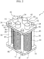
FIG. 2 is a perspective view showing a schematic configuration of the load-applyingdevice 1 according to the embodiment of the present invention. -
FIG. 3 is an exploded view of the load-applyingdevice 1 according to the embodiment of the present invention. -
FIG. 4 is an explanation view for easily illustrating a positional relationship ofrods 40, aflange 45, and asecond plate 20 when thesecond plate 20 is a semitransparent state in the load-applyingdevice 1 according to the embodiment of the present invention. -
FIG. 5A is a top view of the load-applyingdevice 1 according to the embodiment of the present invention. -
FIG. 5B is an offset cross-sectional view taken along line A-A inFIG. 5A . -
FIG. 6A is a cross-sectional view taken along line B-B inFIG. 5A and shows a state where theflange 45 is biased to thesecond plate 20. -
FIG. 6B is a cross-sectional view taken along line B-B inFIG. 5A and shows a state where a lamination coneddisc springs 60 are pushed from the state ofFIG. 6A . -
FIG. 7A is a view in which a rodlength adjustment member 47 is provided in the cross-sectional view taken along line B-B inFIG. 5A and which shows a state where theflange 45 is biased to thesecond plate 20. -
FIG. 7B is a view in which the rodlength adjustment member 47 is provided in the cross-sectional view taken along line B-B inFIG. 5A and which shows a state where the lamination coned disc springs 60 are pushed from the state ofFIG. 7A . -
FIG. 8A is an exploded view of a press-formingdie 100A in which one load-applyingdevice 1 according to the embodiment of the present invention is disposed. -
FIG. 8B is a perspective view when the disposition state of the load-applyingdevice 1 according to the embodiment of the present invention is viewed from adice die member 120 side. -
FIG. 9A is an exploded view of a press-formingdie 100B in which four load-applyingdevices 1 according to the embodiment of the present invention are disposed. -
FIG. 9B is a perspective view when the disposition state of the load-applyingdevice 1 according to the embodiment of the present invention is viewed from the dice diemember 120 side. -
FIG. 10 is a perspective view of a hat-shaped cross-sectional member which is formed by Example of the present invention and Comparative Example. - The inventors found that a lamination coned disc spring was inserted between two plates in a state where the spring is slightly compressed, and by using a reaction force generated when the lamination coned disc spring was further compressed, a load could be easily and stably applied to a press-forming die compared to the related art.
- Hereinafter, an embodiment of the present invention will be described with reference to the drawings based on the above-described findings. First, an object to be applied of a load-applying device for a press-forming die of the present invention will be described.
-
FIGS. 1A to 1C are longitudinal cross-sectional views showing a state where a load-applyingdevice 1 for a press-forming die according to an embodiment of the present invention is applied to a press-formingdie 100 for performing drawing. Hereinafter, based onFIGS. 1A to 1C , an operation of the load-applyingdevice 1 according to the embodiment of the present invention will be described.FIG. 1A shows a state where ametal plate 105 is placed on the press-formingdie 100.FIG. 1B shows a state during the drawing of themetal plate 105.FIG. 1C shows a state immediately before the drawing of themetal plate 105 is completed. - The press-forming
die 100 includes a plurality of die members, that is, apunch die member 110, adice die member 120, and a blank holding diemember 130. The load-applyingdevice 1 according to the present embodiment is mounted on thepunch die member 110. - As shown in
FIG. 1A , themetal plate 105 to be drawn is placed on the blank holding diemember 130. As shown inFIG. 1B , the dice diemember 120 is lowered, and the drawing of themetal plate 105 starts. Moreover, as shown inFIG. 1C , a portion of the load-applyingdevice 1 according to the present embodiment is pushed by the blank holding diemember 130 immediately before the drawing is completed. - At this time, a load shown by a white arrow in
FIG. 1C is applied to the blank holding diemember 130 included in the press-formingdie 100. - According to the load shown by the white arrow, a local additional load separate from the drawing load can be applied to the blank holding die
member 130 immediately before the drawing is completed. The load-applyingdevice 1 according to the present embodiment is used for the application of the additional load. In addition, according to the application of the local additional load by the load-applyingdevice 1 of the present embodiment, a blank holding force can be sufficiently applied to themetal plate 105. As a result, quality of a press-formed part is improved. - The load-applying
device 1 according to the present embodiment is not limited to the example shown inFIGS. 1A to 1C , and may be also applied to other uses. - Next, a structure of the load-applying
device 1 according to the present embodiment will be described.FIG. 2 is a perspective view showing an example of a schematic configuration of the load-applyingdevice 1 according to the present embodiment.FIG. 3 is an exploded view of the load-applyingdevice 1 according to the present embodiment. - The load-applying
device 1 includes afirst plate 10, asecond plate 20,gap fixing members 30,rods 40, and lamination coned disc springs 60. - Each of the
rods 40 includes afirst end 41, asecond end 42, and aflange 45. Theflange 45 is provided between thefirst end 41 and thesecond end 42. Theflange 45 may be integrally formed to therod 40 by cutting or the like, and aseparate flange 45 may be fixed to a rod-shaped member by welding or the like. - The
rods 40 are inserted to centerholes 62 of the plurality of coned disc springs from the first ends 41, and thus, the plurality of coned disc springs are laminated, and lamination coned disc springs 60 are configured. - The first ends 41 of the
rods 40 are inserted to first throughholes 14 provided in thefirst plate 10. Moreover, thefirst plate 10 abuts the lamination coneddisc spring 60. - In addition, the second ends 42 of the
rods 40 are inserted to second throughholes 24 provided in thesecond plate 20. Moreover, thesecond plate 20 abuts theflanges 45. - In this way, the lamination coned disc springs 60 are interposed between the
first plate 10 and thesecond plate 20 via theflanges 45. In this state, a biasing force from the lamination coned disc springs 60 is not applied between thefirst plate 10 and theflange 45. - In the state where the biasing force is not applied, the
gap fixing members 30 are disposed between thefirst plate 10 and thesecond plate 20. Moreover, thefirst plate 10 and thesecond plate 20 are fastened in a mutually approaching direction bybolts 33 which are inserted to throughholes 32 provided in thegap fixing members 30. - Finally, the
first plate 10, thesecond plate 20, and the lamination coned disc springs 60 are fixed by thegap fixing members 30 via theflanges 45 in a state where the lamination coned disc springs 60 are slightly compressed. In this way, thegap fixing members 30 are detachably provided between thefirst plate 10 and thesecond plate 20 and fix a gap between thefirst plate 10 and thesecond plate 20 so as to maintain gaps in which the lamination coned disc springs 60 bias theflanges 45 to thesecond plate 20. According to this configuration, by relatively moving thefirst plate 10 and the second ends 42 of therods 40 in a mutually approaching direction during the press-forming, the lamination coned disc springs 60 can be compressed between thefirst plate 10 and theflanges 45 of therods 40, and thus, a reaction force can be obtained. -
FIG. 4 is an explanation view for easily illustrating positional relationships of therods 40,flanges 45, and thesecond plate 20 when thesecond plate 20 is a semitransparent state in the load-applyingdevice 1 according to the embodiment of the present invention. - Since the lamination coned disc springs 60 are slightly compressed, the biasing force is applied between the
first plate 10 and theflanges 45, and theflanges 45 are biased toward thesecond plate 20. The entire length of each of thegap fixing members 30 is set to apply the biasing force. That is, the entire length of each of thegap fixing members 30 is set so that theflanges 45 are biased to thesecond plate 20 by the lamination coned disc springs 60. - Specifically, the entire length of each of the
gap fixing members 30 is determined to be (a lamination height in a state where the lamination coneddisc spring 60 is not compressed at all) + (a thickness of the flange 45) - (a compressed length of the lamination coneddisc spring 60 when theflange 45 is biased to thesecond plate 20 by the lamination coned disc spring 60). -
FIGS. 5A and 5B are a top view and an offset cross-sectional view of the load-applyingdevice 1 according to the present embodiment respectively.FIG. 5A is the top view.FIG. 5B is the offset cross-sectional view taken along line A-A ofFIG. 5A . - In
FIGS. 5A and 5B , L is (the lamination height in a state where the lamination coneddisc spring 60 is not compressed at all) - (the compressed length of the lamination coneddisc spring 60 when theflange 45 is biased to thesecond plate 20 by the lamination coned disc spring 60). Accordingly, when the length of thegap fixing member 30 is represented by D and the thickness of theflange 45 is represented by F, D = F + L is satisfied. - Here, the compressed length of the lamination coned
disc spring 60 whenflange 45 is biased to thesecond plate 20 by the lamination coneddisc spring 60 is preferably within a range of 5 to 20% with respect to the compressed length when the lamination coneddisc spring 60 is completely compressed. If the range is less than 5%, the biasing force is insufficient, and since lamination coned disc springs move mutually, it is not preferable. On other hand, if the range exceeds 20%, when the press-forming ends and the load-applyingdevice 1 according to the present embodiment does not apply the load to the die member, since the lamination coned disc springs 60 apply excessive dynamic loads to thefirst plate 10 and thesecond plate 20, and thus, it is not preferable. - As long as the
first plate 10, thesecond plate 20, and thegap fixing members 30 are fixed to one another, a fixing method is not particularly limited. In the embodiment shown inFIGS. 2 to 7B , as shown inFIG. 5B ,bolts 33 are inserted to throughholes 22 provided in thesecond plate 20 and throughholes 32 provided in thegap fixing members 30. Moreover, male screws provided in thebolts 33 are screwed tofemale screws 12 provided in thefirst plate 10, andwashers 34 provided in thebolts 33 and thesecond plate 20 are fastened.Washers 31 of thegap fixing members 30 are disposed to stably support thefirst plate 10 and thesecond plate 20. However, thewashers 31 may be omitted. - In the embodiment shown in
FIGS. 2 to 7B , 36 one lamination coneddisc spring 60 is configured by laminating the coned disc springs. The number of the laminated coned disc springs is not limited to 36. The number of the coned disc springs may be appropriately selected to obtain desired stroke and application load in the entire load-applyingdevice 1 according to the present embodiment. Moreover, similarly, a lamination method of the coned disc springs may also be appropriately selected. For example, there is a serial lamination method in which all coned disc springs configuring one row of the lamination coned disc springs are arranged in the same posture, a parallel-serial lamination method in which some coned disc springs are arranged in reverse postures, or the like. In addition, in the parallel-serial lamination method, a lamination height is increased and a repulsive force (application load) is increased compared to the serial lamination method as the number of the coned disc springs arranged in the reverse posture is increased. - Next, an operation of the load-applying
device 1 will be described. In the operation of the load-applyingdevice 1, there is a case where the first ends 41 of therods 40 are pushed and operated and a case where the second ends 42 are pushed and operated. The "push" means that first ends 41 or the second ends 42 are moved in the directions in which the laminated coned disc springs 60 are compressed. The direction in which each of the lamination coned disc springs 60 is compressed is an axial center direction of therod 40 which is inserted to the lamination coneddisc spring 60. Here, the case where the second ends 42 are pushed will be described. -
FIGS. 6A and 6B are cross-sectional views taken along line B-B ofFIG. 5A .FIG. 6A shows a state where theflanges 45 are biased to thesecond plate 20.FIG. 6B shows a state where the lamination coned disc springs 60 are pushed from the state ofFIG. 6A . - The second ends 42 are pushed by the die member to which the load is to be applied. As shown in
FIGS. 1A to 1C , in the application example in which the load is applied to the blank holding diemember 130, thefirst plate 10 is mounted on thepunch die member 110, and the blank holding diemember 130 pushes the second ends 42 of therods 40. Hereinafter, according to this application example, the operation of the load-applyingdevice 1 of the present embodiment will be described. - When the load-applying
device 1 according to the present embodiment is not operated, a state (hereinafter, may be also referred to as a "normal state") in which theflanges 45 are biased to thesecond plate 20 becomes, that is, the entire length of the lamination coneddisc spring 60 becomes L. The blank holding diemember 130 pushes the second ends 42 of therods 40 in the direction, in which the lamination coned disc springs 60 are compressed, by a length P from the normal state. As a result, a reaction force shown by a white arrow ofFIG. 6B is generated. Moreover, the reaction force acts on the blank holding diemember 130 while the blank holding diemember 130 pushes the second ends 42. The reaction force acting on the blank holding diemember 130 is the application load. Moreover, the length P ofFIG. 6B is a stroke. - The application load per one
rod 40 is represented by k × P. Here, k is a spring constant of the entire lamination coneddisc spring 60 in onerod 40. In the case of the embodiment shown inFIGS. 2 to 7B , k is the spring constant of the entire of 36 coned disc springs which are laminated. - Next, a case where the application load which is larger by k × S than k × P per one rod is modified to be applied to the blank holding die
member 130 will be described. -
FIGS. 7A and 7B are views showing the load-applyingdevice 1 according to the present embodiment when rodlength adjustment members 47 detachable to the second ends 42 of therods 40 are mounted.FIGS. 7A and 7B are views showing when the detachable rodlength adjustment members 47 are mounted in the cross-sectional view taken along line B-B ofFIG. 5A .FIG. 7A shows a state where theflanges 45 are biased to thesecond plate 20.FIG. 7B shows a state where the lamination coned disc springs 60 are pushed from the state ofFIG. 7A . - As shown in
FIGS. 7A and 7B , since the thickness of each of the rodlength adjustment members 47 is S, the stoke becomes P + S, and the application load of k × (P + S) can act on the blank holding diemember 130. - Even when the length R shown in
FIG. 7A is changed, that is, even when the protruding length of each of therods 40 from thesecond plate 20 in the normal state is changed, similar effects are obtained. However, if a plurality of kinds of rodlength adjustment members 47 having different thicknesses S are prepared, the magnitude of the application load can be more easily adjusted, and thus, it is preferable. - Moreover, the entire length (hereinafter, referred to as "the entire length in a normal state") of the load-applying
device 1 according to the present embodiment in the normal state can be changed by changing the length of L in the normal state. With respect to the entire length in a normal state, a plurality of kinds ofgap fixing members 30 having different lengths D (refer toFIG. 5B ) described above may be prepared. - The plurality of kinds of rod
length adjustment members 47 having different thicknesses S and the plurality of kinds ofgap fixing members 30 having different lengths D are prepared respectively, and thus, a desired combination of the stroke and the application load can be obtained. - In addition, a detachable first plate thickness adjustment member may be mounted on a surface opposite to the second plate side in the
first plate 10. With the first plate thickness adjustment member, if a plurality of kinds of first plate thickness adjustment members having different thicknesses are prepared, a desired combination of the stroke and the application load can be more easily obtained. - Moreover, a detachable flange thickness adjustment member may be mounted on each of the
flanges 45. Also in the flange thickness adjustment member, if a plurality of kinds of flange thickness adjustment members having different thicknesses are prepared, a desired combination of the stroke and the application load can be more easily obtained. - In this way, by changing at least one of the number of the coned disc springs, the directions of the coned disc springs, the kind of the coned disc springs, the thickness of the
flanges 45, thickness of thefirst plate 10, the lengths of thegap fixing members 30, and the lengths of thesecond end 42 sides of therods 30 in the load-applyingdevice 1, the load applied to the press-forming die and the stroke can be easily adjusted. - Moreover, the above described configurations only exemplify the embodiment of the present invention, and various modifications can be applied to the present invention within scope of Claims.
- For example, in the above-described explanation, four
rods 30 and four lamination coned disc springs are shown as the load-applyingdevice 1. However, the number of therods 30 and the lamination coned disc springs is not limited to four, and may be one or more. - However, when the number of the
rods 30 is plural (two or more), for example, each of the rod length adjustment members having thicknesses different from one another is detachably mounted on thesecond end 42 side of each rod, and thus, the load-applying device can be easily applied to even a position corresponding to an inclined surface of the die. - When the load-applying device is applied to the position corresponding to the inclined surface of the die, an end of each of the rod length adjustment member contacting the inclined surface of the die has a hemisphere shape or a shape which comes into surface contact with the inclined surface of the die, and thus, the load can be more appropriately applied.
- Moreover, in the application example shown in
FIGS. 1A to 1C , in a state where thesecond plate 20 is mounted on thepunch die member 110 and theflanges 45 abut thefirst plate 10, the first ends 41 of therods 40 may be pushed by the blank holding diemember 130. - The present invention is further described based on Examples. However, the condition of Example is an example of conditions which are adopted for conforming enablement and effects of the present invention, and the present invention is not limited to the example of the conditions. The present invention can adopt various conditions as long as the object of the present invention can be achieved without departing from the gist of the present invention.
-
FIGS. 8A and8B are views showing an example in which one load-applyingdevice 1 shown inFIG. 4 is disposed in a press-formingdie 100A.FIG. 8A is an exploded view of the press-formingdie 100A.FIG. 8B is a perspective view when the disposition state of the load-applyingdevice 1 shown inFIG. 4 is viewed from the dice diemember 120 side. - The press-forming
die 100A shown inFIG. 8A includes thepunch die member 110, the dice diemember 120, and the blank holding diemember 130. Moreover, the blank holding diemember 130 is divided into three divided die members forblank holding - In this way, since the blank holding die
member 130 is divided into three, the blank holding force can be reliably transferred to the metal plate to be press-formed. In the press-formingdie 100A shown inFIG. 8A , one load-applyingdevice 1 is disposed on thepunch die member 110 so that, in the last period of the press-forming, a local load is applied only to the divided die member forblank holding 132c among the die members forblank holding - The divided die member for
blank holding 132c pushes the second ends 42 of fourrods 40 in the last period of the press-forming, the divided die member forblank holding 132c receives the reaction force of the lamination coneddisc spring 60, and the application load is applied to the divided die member forblank holding 132c. - Moreover, the second ends 42 of the
rods 40 are pushed, and thus, the first ends 41 further protrude. Concave portions (dashed lines) are provided in thepunch die member 110 so that the first ends 41 do not interfere with thepunch die member 110 due to the protrusion of the first ends. The concave portions are provided, thefirst plate 10 is fixed to thepunch die member 110, and thus, the load-applyingdevice 1 is disposed in thepunch die member 110. -
FIGS. 9A and9B are views showing an example in which four load-applying devices 1 (1a-1, 1a-2, 1b, 1c) shown inFIG. 4 is disposed in a press-formingdie 100B.FIG. 9A is an exploded view of the press-formingdie 100B.FIG. 9B is a perspective view when the disposition state of the load-applyingdevice 1 shown inFIG. 4 is viewed from the dice diemember 120 side. - Except for the number of the disposed load-applying
devices 1, the press-formingdie 100A shown inFIG. 9A and the press-formingdie 100B shown inFIG. 8A are the same as each other. Moreover, in Example 2, rodlength adjustment members 47 are detachably mounted on therods 40 of the load-applyingdevice 1 shown inFIG. 4 . - The load-applying
devices 1a-1 and 1a-2 apply the application load to the divided die member forblank holding 132a. The load-applyingdevices 1b applies the application load to the divided die member forblank holding 132b. The load-applyingdevices 1c applies the application load to the divided die member forblank holding 132c. - The divided die member for
blank holding 132a pushes the second ends 42 of eightrods 40 having two load-applyingdevices 1a-1 and 1a-2 in the last period of the press-forming, the divided die member forblank holding 132a receives the reaction force from the lamination coneddisc spring 60, and the application load is applied to the divided die member forblank holding 132a. - In addition, the divided die member for
blank holding 132b pushes rodlength adjustment members 47 which are mounted on the second ends 42 of fourrods 40 included in the load-applyingdevices 1b in the last period of the press-forming, the divided die member forblank holding 132b receives the reaction force from the lamination coneddisc spring 60, and the application load is applied to the divided die member forblank holding 132b. - Also in the divided die member for
blank holding 132c, except that the thicknesses of the rodlength adjustment members 47 are different those of the rodlength adjustment members 47 of the divided die member forblank holding 132b, similar to the load-applyingdevice 1a, the load-applyingdevice 1c is disposed in thepunch die member 110. - In this way, when the metal plate is press-formed by the press-forming
die 100B in which four load-applying devices 1 (1a-1, 1a-2, 1b, and 1c) are disposed, lengths D (mm) of thegap fixing members 30, the thicknesses S (mm) of the rod length adjustment members, strokes (mm), and application loads (MPa) are shown in Table 1. Moreover, the thickness S of the rod length adjustment member being 0 mm means a state where the rodlength adjustment member 47 is not mounted, that is, the state shown inFIGS. 6A and 6B .[Table 1] 1a-1 1a-2 1b 1c Length of Gap Fixing Member, D (mm) 160 160 160 159 Thickness of Rod Length Adjustment Member, S (mm) 0 0 4 5 Stroke (mm) 6 6 10 10 Application Load (MPa) 111 111 189 208 - As is obvious from Table 1, it was confirmed that both of the stroke and the application load could be changed by changing the thickness S of the rod length adjustment member 47 (including the case where the rod
length adjustment member 47 was not mounted) and the length D of thegap fixing member 30, that is, by changing S + D. - Moreover, it was confirmed that application loads different from one another could act on three divided die members for
blank holding - Accordingly, it was confirmed that the load-applying
devices 1 were disposed in the press-formingdie 100, and as the additional load separate from the press-forming load, the load having the necessary magnitude could be applied to the die member in which a local load application is required in the last period of the press-forming among the plurality of die members included in the press-formingdie 100. - The following Steel sheets A to C were prepared.
[Table 2] Steel Kind Standard Sheet Thickness (mm) Yield Point (MPa) Tensile Strength (MPa) Elongation (%) Steel Sheet A General Cold Rolled Steel Sheet JIS G3141 SPCD 1.0 153 315 47 Steel Sheet B High Strength Cold Rolled Steel Sheet JSC 440W 1.0 364 468 35 Steel Sheet C High Strength Cold Rolled Steel Sheet JSC 590Y 1.0 374 614 30 - In Comparative Examples A to C, the steel sheets A to C were formed in the state where the load-applying device was removed in the die structure shown in
FIG. 8A , and a hat-shaped cross-sectional member shown inFIG. 10 was press-formed. In the shape shown inFIG. 10 , a target value of a distance P was set to 75 mm, and a target value of a distance Q was set to 110 mm. - In Examples 1A to 1C, the steel sheets A to C was formed using the die structure shown in
FIG. 8A , and the hat-shaped cross-sectional member having the shape shown inFIG. 10 was press-formed. - In Examples 2A to 2C, the steel sheets A to C were formed using the die structure shown in
FIG. 9A , and the hat-shaped cross-sectional member having the shape shown inFIG. 10 was press-formed. - With respect to Comparative Examples A to C, Examples 1A to 1C, and Examples 2A to 2C, the distances P and distances Q of the hat-shaped members after the forming were measured, and thus, a spring back amount was evaluated. The results are shown in Table 3 below.
[Table 3] Steel Sheet Load-applying Device Distance P (mm) Distance D (mm) Comparative Example A Steel Sheet A Not Present 82.2 119.1 Comparative Example B Steel Sheet B Not Present 89.6 126.0 Comparative Example C Steel Sheet C Not Present 93.0 132.8 Example 1A Steel Sheet A One ( FIG. 8A )76.8 112.8 Example 1B Steel Sheet B One ( FIG. 8A )78.7 115.8 Example 1C Steel Sheet C One ( FIG. 8A )81.5 118.7 Example 2A Steel Sheet A Four ( FIG. 9A )75.8 112.5 Example 2B Steel Sheet B Four ( FIG. 9A )77.8 113.6 Example 2C Steel Sheet C Four ( FIG. 9A )79.4 116.3 - As shown in Table 3, compared to Comparative Examples A, B, and C in which the load-applying device is not used, it is understood that the spring back amount is improved in Examples 1A to 1C. Moreover, in the Examples 2A to 2C in which the load-applying devices are provided in four places, particularly, it is understood that expansion of the distance P is suppressed.
- In this way, compared to the related art, according to the present invention, it is possible to easily achieve improvement of the spring back amount at low cost.
- As described above, according to the present invention, both of the stroke and the application load can be easily adjusted. Accordingly, the load-applying device for a press-forming die is disposed at an appropriate position of the press-forming die, values of both of the stroke and the application load are combined to desired values, the local load is applied to a specific die member included in the press-forming die, and quality of the press-formed part can be improved. Therefore, the present invention has high industrial values.
-
- 1: load-applying device for press-forming die
- 10: first plate
- 12: female screw
- 14: first through hole
- 20: second plate
- 22: through hole
- 24: second through hole
- 30: gap fixing member
- 31: washer
- 32: through hole
- 33: bolt
- 34: washer
- 40: rod
- 41: first end
- 42: second end
- 45: flange
- 47: rod length adjustment member
- 49: surface opposite to second end
- 60: lamination coned disc spring
- 62: center hole
- 100: press-forming die
- 110: punch die member
- 120: dice die member
- 130: blank holding die member
- 132a, 132b, and 132c: divided die member for blank holding
- D: length of gap fixing member
- F: thickness of flange
- L: length in normal state of lamination coned disc spring
- P: stroke
Claims (8)
- A load-applying device (1) for a press-forming die (100), the device comprising:a rod (40) which includes a first end (41), a second end (42), and a flange (45) which is provided between the first end (41) and the second end (42);a lamination coned disc spring (60) which has a plurality of coned disc springs that are laminated, wherein the coned disc springs (60) have a center hole (62) in which the first end (41) of the rod (40) is inserted;a first plate (10) which includes a first through hole (14) to which the first end (41) of the rod (40) is inserted, the first plate (10) abutting the lamination coned disc spring (60);a second plate (20) which includes a second through hole (24) to which the second end (42) of the rod (40) is inserted, the second plate (20) abutting the flange (45); and a gap fixing member (30) which is detachably provided between the first plate (10) and the second plate (20) and fixes a gap between the first plate (10) and the second plate (20) so as to maintain the gap by which the lamination coned disc spring (60) biases the flange (45) to the second plate (20),wherein the second end (42) of the rod (40) protrudes from the second plate (20) andthe second end (42) moves in an approaching direction relative to the first plate (10) during press-forming, and the lamination coned disc spring (60) is compressed.
- The load-applying device (1) for a press-forming die (100) according to Claim 1,
wherein the rod (40) includes a rod length adjustment member (47) which is detachably mounted on the second end (42). - The load-applying device (1) for a press-forming die according to Claim 1, wherein the first plate (10) includes a first plate thickness adjustment member which is detachably mounted on a surface opposite to the second plate (20).
- The load-applying device (1) for a press-forming die according to Claim 1, wherein the flange (45) includes a flange thickness adjustment member which is detachably mounted on the flange (45).
- The load-applying device (1) for a press-forming die according to Claim 1, wherein a plurality of the rods (40) and the lamination coned disc springs (60) are provided.
- The load-applying device (1) for a press-forming die according to Claim 1, wherein a plurality of the rods (40) and the lamination coned disc springs (60) are provided,
wherein each of the plurality of rods (40) includes a rod length adjustment member (47) which is detachably mounted on the second end side, and
wherein a thickness of at least one of a plurality of the rod length adjustment members is different from the thicknesses of other rod length adjustment members. - A press-forming die (100) comprising:a first die member (120) which is disposed above a metal plate (105) to be processed;a second die member (110) which is disposed below the metal plate (105);a blank holding die member (130) which presses the metal plate (105) to the first die member (120) or the second die member (110) during press working; andthe load-applying device (1) according to any one of Claims 1 to 6 which is provided between the first die member (120) and the blank holding die member (130) or between the second die member (110) and the blank holding die member (130).
- A press-forming method comprising:disposing a metal plate (105) and processing the metal plate (105) by the press-forming die (100) according to Claim 7; andchanging at least one of, the number of the coned disc springs (60), a direction of the coned disc spring (60), a kind of the coned disc spring (60), a thickness of the flange (45), a thickness of the first plate (10), a length of the gap fixing member (30), and a length of the second end side (42) of the rod (40) in the load-applying device (1), thereby adjusting a load and a stroke applied to the press-forming die (100), and performing press-forming.
Applications Claiming Priority (2)
| Application Number | Priority Date | Filing Date | Title |
|---|---|---|---|
| JP2011042770 | 2011-02-28 | ||
| PCT/JP2012/054582 WO2012117967A1 (en) | 2011-02-28 | 2012-02-24 | Load applying device, press-molding die, press-molding method |
Publications (3)
| Publication Number | Publication Date |
|---|---|
| EP2682200A1 EP2682200A1 (en) | 2014-01-08 |
| EP2682200A4 EP2682200A4 (en) | 2017-02-01 |
| EP2682200B1 true EP2682200B1 (en) | 2021-07-21 |
Family
ID=46757904
Family Applications (1)
| Application Number | Title | Priority Date | Filing Date |
|---|---|---|---|
| EP12752433.8A Active EP2682200B1 (en) | 2011-02-28 | 2012-02-24 | Load applying device, press-molding die, press-molding method |
Country Status (6)
| Country | Link |
|---|---|
| US (1) | US9481021B2 (en) |
| EP (1) | EP2682200B1 (en) |
| JP (1) | JP5866336B2 (en) |
| CN (1) | CN103402667A (en) |
| CA (1) | CA2828189C (en) |
| WO (1) | WO2012117967A1 (en) |
Families Citing this family (3)
| Publication number | Priority date | Publication date | Assignee | Title |
|---|---|---|---|---|
| US20140137624A1 (en) * | 2012-08-15 | 2014-05-22 | Kenneth L. Smedberg | Die cushion system and method |
| CN106111814B (en) * | 2016-08-09 | 2019-02-01 | 机械科学研究总院 | Drawing die |
| CN114472651A (en) * | 2022-02-11 | 2022-05-13 | 杭州宇乘五金科技有限公司 | Dish spring mould that pressurizes by force with letter sorting function |
Family Cites Families (18)
| Publication number | Priority date | Publication date | Assignee | Title |
|---|---|---|---|---|
| US1827440A (en) * | 1929-01-30 | 1931-10-13 | Marquette Tool & Mfg Co | Spring cushion for presses |
| US2084456A (en) * | 1935-01-07 | 1937-06-22 | Fredrich J Rode | Bolster pin holder |
| US2387266A (en) * | 1941-11-17 | 1945-10-23 | Holland Co | Vehicle suspension |
| US2708110A (en) * | 1953-09-25 | 1955-05-10 | Murray G Clay | Belleville variety compression springs |
| US2821380A (en) * | 1953-10-28 | 1958-01-28 | Alco Products Inc | Spring group |
| US3942354A (en) * | 1974-11-14 | 1976-03-09 | Dayton Progress Corporation | Die unit with quick change features |
| JPS6471530A (en) | 1987-09-09 | 1989-03-16 | Kobe Steel Ltd | Fluid pressure molding processing equipment |
| JPH0715610Y2 (en) | 1989-02-08 | 1995-04-12 | 三住商事株式会社 | Wrinkle clamp support mechanism in press working equipment |
| JPH03207531A (en) | 1990-01-08 | 1991-09-10 | Miyama Kogyo Kk | Metal drawing press |
| JPH10305332A (en) | 1996-08-23 | 1998-11-17 | Isao Takatsuka | Pressure unit with plural springs |
| ES2146518B1 (en) * | 1997-07-15 | 2001-02-16 | Muller Carranza Luis | IMPROVEMENTS INTRODUCED IN THE GUIDELINES FOR COLUMNS OF SPRINGS OF SUPERPOSED CONICAL DISCS. |
| JP3772965B2 (en) | 2001-04-27 | 2006-05-10 | トヨタ自動車株式会社 | Press mold and press working method |
| US7243521B2 (en) * | 2002-11-14 | 2007-07-17 | Komatsu Ltd. | Cushion pin, wear plate, load supporting device, die cushion, press machine and pressing method |
| JP2004237347A (en) | 2003-02-07 | 2004-08-26 | Saidaiji Sangyo Kk | Press forming method and press forming apparatus |
| JP2004344925A (en) | 2003-05-22 | 2004-12-09 | Nippon Steel Corp | Die device for press molding and press molding method |
| US7854425B2 (en) * | 2005-12-21 | 2010-12-21 | Halliburton Energy Services, Inc. | Belleville spring guide system |
| JP4771177B2 (en) | 2008-02-22 | 2011-09-14 | 財団法人北九州産業学術推進機構 | Dynamically controllable wrinkle holding mechanism in drawing |
| CN201279549Y (en) * | 2008-10-06 | 2009-07-29 | 广州普什精密模具有限公司 | Double-float drawing die for back seat-pan stamping piece of vehicle seat |
-
2012
- 2012-02-24 CA CA2828189A patent/CA2828189C/en active Active
- 2012-02-24 CN CN2012800104692A patent/CN103402667A/en active Pending
- 2012-02-24 JP JP2013502290A patent/JP5866336B2/en active Active
- 2012-02-24 EP EP12752433.8A patent/EP2682200B1/en active Active
- 2012-02-24 US US14/001,343 patent/US9481021B2/en active Active
- 2012-02-24 WO PCT/JP2012/054582 patent/WO2012117967A1/en active Application Filing
Non-Patent Citations (1)
| Title |
|---|
| None * |
Also Published As
| Publication number | Publication date |
|---|---|
| US20130327115A1 (en) | 2013-12-12 |
| JPWO2012117967A1 (en) | 2014-07-07 |
| EP2682200A1 (en) | 2014-01-08 |
| JP5866336B2 (en) | 2016-02-17 |
| WO2012117967A1 (en) | 2012-09-07 |
| EP2682200A4 (en) | 2017-02-01 |
| CA2828189A1 (en) | 2012-09-07 |
| US9481021B2 (en) | 2016-11-01 |
| CN103402667A (en) | 2013-11-20 |
| CA2828189C (en) | 2016-09-06 |
Similar Documents
| Publication | Publication Date | Title |
|---|---|---|
| CN108202093B (en) | Method for producing press-molded article, mandrel, and press-molded article | |
| EP2682200B1 (en) | Load applying device, press-molding die, press-molding method | |
| US20180369893A1 (en) | Wedge drive | |
| EP0983808A1 (en) | Cam slide driving apparatus | |
| CN104368681B (en) | Wedge mechanism | |
| CN102078896B (en) | Stretch-forming device and method for stretch forming a workpiece and stretch-formed part | |
| US8245557B2 (en) | Press brake for bending sheets | |
| US10773293B2 (en) | Hydraulic punch device | |
| JP2010279987A (en) | Cam device | |
| WO2010042962A3 (en) | Bending press having support bearing device for drive means | |
| MX2021008959A (en) | Press molding method and press machine. | |
| EP1799372B1 (en) | Method and device for the production and/or machining of pieces | |
| CN111069434B (en) | Stamping die and working method thereof | |
| JP2006247675A (en) | Punch for press working and press working method | |
| US11565302B2 (en) | Press working apparatus, and setting method and maintenance method thereof | |
| CN213052279U (en) | Stamping forming device of aluminum alloy sheet metal component | |
| CN112338050A (en) | Use method of copper bar punching die | |
| US20150258702A1 (en) | Auxiliary plate for sheet-member processing device and sheet-member processing device using the same | |
| KR200489689Y1 (en) | Pressure spring for pressure reinforcement device of vise | |
| CN110121411B (en) | Wedge drive and method for producing an optimally guided wedge drive | |
| JP7050984B2 (en) | Method of reducing residual stress at the edge of the work | |
| JP2014111262A (en) | Position adjustment device for die of press bending process device | |
| US20220118495A1 (en) | Press brake and method of operating press brake | |
| CN212238882U (en) | Bending and punching die | |
| KR200444471Y1 (en) | Progressive mold |
Legal Events
| Date | Code | Title | Description |
|---|---|---|---|
| PUAI | Public reference made under article 153(3) epc to a published international application that has entered the european phase |
Free format text: ORIGINAL CODE: 0009012 |
|
| 17P | Request for examination filed |
Effective date: 20130926 |
|
| AK | Designated contracting states |
Kind code of ref document: A1 Designated state(s): AL AT BE BG CH CY CZ DE DK EE ES FI FR GB GR HR HU IE IS IT LI LT LU LV MC MK MT NL NO PL PT RO RS SE SI SK SM TR |
|
| DAX | Request for extension of the european patent (deleted) | ||
| RA4 | Supplementary search report drawn up and despatched (corrected) |
Effective date: 20170105 |
|
| RIC1 | Information provided on ipc code assigned before grant |
Ipc: B21D 24/12 20060101AFI20161223BHEP Ipc: B21D 24/02 20060101ALI20161223BHEP |
|
| STAA | Information on the status of an ep patent application or granted ep patent |
Free format text: STATUS: EXAMINATION IS IN PROGRESS |
|
| 17Q | First examination report despatched |
Effective date: 20181120 |
|
| STAA | Information on the status of an ep patent application or granted ep patent |
Free format text: STATUS: EXAMINATION IS IN PROGRESS |
|
| RAP1 | Party data changed (applicant data changed or rights of an application transferred) |
Owner name: NIPPON STEEL CORPORATION Owner name: H-ONE CO., LTD. |
|
| GRAP | Despatch of communication of intention to grant a patent |
Free format text: ORIGINAL CODE: EPIDOSNIGR1 |
|
| STAA | Information on the status of an ep patent application or granted ep patent |
Free format text: STATUS: GRANT OF PATENT IS INTENDED |
|
| INTG | Intention to grant announced |
Effective date: 20210211 |
|
| GRAS | Grant fee paid |
Free format text: ORIGINAL CODE: EPIDOSNIGR3 |
|
| GRAA | (expected) grant |
Free format text: ORIGINAL CODE: 0009210 |
|
| STAA | Information on the status of an ep patent application or granted ep patent |
Free format text: STATUS: THE PATENT HAS BEEN GRANTED |
|
| RAP1 | Party data changed (applicant data changed or rights of an application transferred) |
Owner name: H-ONE CO., LTD. |
|
| AK | Designated contracting states |
Kind code of ref document: B1 Designated state(s): AL AT BE BG CH CY CZ DE DK EE ES FI FR GB GR HR HU IE IS IT LI LT LU LV MC MK MT NL NO PL PT RO RS SE SI SK SM TR |
|
| REG | Reference to a national code |
Ref country code: GB Ref legal event code: FG4D |
|
| REG | Reference to a national code |
Ref country code: CH Ref legal event code: EP |
|
| REG | Reference to a national code |
Ref country code: DE Ref legal event code: R096 Ref document number: 602012076156 Country of ref document: DE |
|
| REG | Reference to a national code |
Ref country code: AT Ref legal event code: REF Ref document number: 1412126 Country of ref document: AT Kind code of ref document: T Effective date: 20210815 |
|
| REG | Reference to a national code |
Ref country code: IE Ref legal event code: FG4D |
|
| REG | Reference to a national code |
Ref country code: LT Ref legal event code: MG9D |
|
| REG | Reference to a national code |
Ref country code: NL Ref legal event code: MP Effective date: 20210721 |
|
| REG | Reference to a national code |
Ref country code: AT Ref legal event code: MK05 Ref document number: 1412126 Country of ref document: AT Kind code of ref document: T Effective date: 20210721 |
|
| PG25 | Lapsed in a contracting state [announced via postgrant information from national office to epo] |
Ref country code: FI Free format text: LAPSE BECAUSE OF FAILURE TO SUBMIT A TRANSLATION OF THE DESCRIPTION OR TO PAY THE FEE WITHIN THE PRESCRIBED TIME-LIMIT Effective date: 20210721 Ref country code: ES Free format text: LAPSE BECAUSE OF FAILURE TO SUBMIT A TRANSLATION OF THE DESCRIPTION OR TO PAY THE FEE WITHIN THE PRESCRIBED TIME-LIMIT Effective date: 20210721 Ref country code: NL Free format text: LAPSE BECAUSE OF FAILURE TO SUBMIT A TRANSLATION OF THE DESCRIPTION OR TO PAY THE FEE WITHIN THE PRESCRIBED TIME-LIMIT Effective date: 20210721 Ref country code: NO Free format text: LAPSE BECAUSE OF FAILURE TO SUBMIT A TRANSLATION OF THE DESCRIPTION OR TO PAY THE FEE WITHIN THE PRESCRIBED TIME-LIMIT Effective date: 20211021 Ref country code: PT Free format text: LAPSE BECAUSE OF FAILURE TO SUBMIT A TRANSLATION OF THE DESCRIPTION OR TO PAY THE FEE WITHIN THE PRESCRIBED TIME-LIMIT Effective date: 20211122 Ref country code: RS Free format text: LAPSE BECAUSE OF FAILURE TO SUBMIT A TRANSLATION OF THE DESCRIPTION OR TO PAY THE FEE WITHIN THE PRESCRIBED TIME-LIMIT Effective date: 20210721 Ref country code: LT Free format text: LAPSE BECAUSE OF FAILURE TO SUBMIT A TRANSLATION OF THE DESCRIPTION OR TO PAY THE FEE WITHIN THE PRESCRIBED TIME-LIMIT Effective date: 20210721 Ref country code: BG Free format text: LAPSE BECAUSE OF FAILURE TO SUBMIT A TRANSLATION OF THE DESCRIPTION OR TO PAY THE FEE WITHIN THE PRESCRIBED TIME-LIMIT Effective date: 20211021 Ref country code: AT Free format text: LAPSE BECAUSE OF FAILURE TO SUBMIT A TRANSLATION OF THE DESCRIPTION OR TO PAY THE FEE WITHIN THE PRESCRIBED TIME-LIMIT Effective date: 20210721 Ref country code: SE Free format text: LAPSE BECAUSE OF FAILURE TO SUBMIT A TRANSLATION OF THE DESCRIPTION OR TO PAY THE FEE WITHIN THE PRESCRIBED TIME-LIMIT Effective date: 20210721 Ref country code: HR Free format text: LAPSE BECAUSE OF FAILURE TO SUBMIT A TRANSLATION OF THE DESCRIPTION OR TO PAY THE FEE WITHIN THE PRESCRIBED TIME-LIMIT Effective date: 20210721 |
|
| PG25 | Lapsed in a contracting state [announced via postgrant information from national office to epo] |
Ref country code: PL Free format text: LAPSE BECAUSE OF FAILURE TO SUBMIT A TRANSLATION OF THE DESCRIPTION OR TO PAY THE FEE WITHIN THE PRESCRIBED TIME-LIMIT Effective date: 20210721 Ref country code: LV Free format text: LAPSE BECAUSE OF FAILURE TO SUBMIT A TRANSLATION OF THE DESCRIPTION OR TO PAY THE FEE WITHIN THE PRESCRIBED TIME-LIMIT Effective date: 20210721 Ref country code: GR Free format text: LAPSE BECAUSE OF FAILURE TO SUBMIT A TRANSLATION OF THE DESCRIPTION OR TO PAY THE FEE WITHIN THE PRESCRIBED TIME-LIMIT Effective date: 20211022 |
|
| REG | Reference to a national code |
Ref country code: DE Ref legal event code: R097 Ref document number: 602012076156 Country of ref document: DE |
|
| PG25 | Lapsed in a contracting state [announced via postgrant information from national office to epo] |
Ref country code: DK Free format text: LAPSE BECAUSE OF FAILURE TO SUBMIT A TRANSLATION OF THE DESCRIPTION OR TO PAY THE FEE WITHIN THE PRESCRIBED TIME-LIMIT Effective date: 20210721 |
|
| PLBE | No opposition filed within time limit |
Free format text: ORIGINAL CODE: 0009261 |
|
| STAA | Information on the status of an ep patent application or granted ep patent |
Free format text: STATUS: NO OPPOSITION FILED WITHIN TIME LIMIT |
|
| PG25 | Lapsed in a contracting state [announced via postgrant information from national office to epo] |
Ref country code: SM Free format text: LAPSE BECAUSE OF FAILURE TO SUBMIT A TRANSLATION OF THE DESCRIPTION OR TO PAY THE FEE WITHIN THE PRESCRIBED TIME-LIMIT Effective date: 20210721 Ref country code: SK Free format text: LAPSE BECAUSE OF FAILURE TO SUBMIT A TRANSLATION OF THE DESCRIPTION OR TO PAY THE FEE WITHIN THE PRESCRIBED TIME-LIMIT Effective date: 20210721 Ref country code: RO Free format text: LAPSE BECAUSE OF FAILURE TO SUBMIT A TRANSLATION OF THE DESCRIPTION OR TO PAY THE FEE WITHIN THE PRESCRIBED TIME-LIMIT Effective date: 20210721 Ref country code: EE Free format text: LAPSE BECAUSE OF FAILURE TO SUBMIT A TRANSLATION OF THE DESCRIPTION OR TO PAY THE FEE WITHIN THE PRESCRIBED TIME-LIMIT Effective date: 20210721 Ref country code: CZ Free format text: LAPSE BECAUSE OF FAILURE TO SUBMIT A TRANSLATION OF THE DESCRIPTION OR TO PAY THE FEE WITHIN THE PRESCRIBED TIME-LIMIT Effective date: 20210721 Ref country code: AL Free format text: LAPSE BECAUSE OF FAILURE TO SUBMIT A TRANSLATION OF THE DESCRIPTION OR TO PAY THE FEE WITHIN THE PRESCRIBED TIME-LIMIT Effective date: 20210721 |
|
| 26N | No opposition filed |
Effective date: 20220422 |
|
| PG25 | Lapsed in a contracting state [announced via postgrant information from national office to epo] |
Ref country code: IT Free format text: LAPSE BECAUSE OF FAILURE TO SUBMIT A TRANSLATION OF THE DESCRIPTION OR TO PAY THE FEE WITHIN THE PRESCRIBED TIME-LIMIT Effective date: 20210721 |
|
| REG | Reference to a national code |
Ref country code: DE Ref legal event code: R119 Ref document number: 602012076156 Country of ref document: DE |
|
| PG25 | Lapsed in a contracting state [announced via postgrant information from national office to epo] |
Ref country code: MC Free format text: LAPSE BECAUSE OF FAILURE TO SUBMIT A TRANSLATION OF THE DESCRIPTION OR TO PAY THE FEE WITHIN THE PRESCRIBED TIME-LIMIT Effective date: 20210721 |
|
| REG | Reference to a national code |
Ref country code: CH Ref legal event code: PL |
|
| REG | Reference to a national code |
Ref country code: BE Ref legal event code: MM Effective date: 20220228 |
|
| PG25 | Lapsed in a contracting state [announced via postgrant information from national office to epo] |
Ref country code: LU Free format text: LAPSE BECAUSE OF NON-PAYMENT OF DUE FEES Effective date: 20220224 |
|
| PG25 | Lapsed in a contracting state [announced via postgrant information from national office to epo] |
Ref country code: FR Free format text: LAPSE BECAUSE OF NON-PAYMENT OF DUE FEES Effective date: 20220228 |
|
| PG25 | Lapsed in a contracting state [announced via postgrant information from national office to epo] |
Ref country code: LI Free format text: LAPSE BECAUSE OF NON-PAYMENT OF DUE FEES Effective date: 20220228 Ref country code: IE Free format text: LAPSE BECAUSE OF NON-PAYMENT OF DUE FEES Effective date: 20220224 Ref country code: DE Free format text: LAPSE BECAUSE OF NON-PAYMENT OF DUE FEES Effective date: 20220901 Ref country code: CH Free format text: LAPSE BECAUSE OF NON-PAYMENT OF DUE FEES Effective date: 20220228 |
|
| PG25 | Lapsed in a contracting state [announced via postgrant information from national office to epo] |
Ref country code: BE Free format text: LAPSE BECAUSE OF NON-PAYMENT OF DUE FEES Effective date: 20220228 |
|
| PGFP | Annual fee paid to national office [announced via postgrant information from national office to epo] |
Ref country code: GB Payment date: 20230227 Year of fee payment: 12 |
|
| PG25 | Lapsed in a contracting state [announced via postgrant information from national office to epo] |
Ref country code: HU Free format text: LAPSE BECAUSE OF FAILURE TO SUBMIT A TRANSLATION OF THE DESCRIPTION OR TO PAY THE FEE WITHIN THE PRESCRIBED TIME-LIMIT; INVALID AB INITIO Effective date: 20120224 |