EP3578294B1 - Vorrichtung und verfahren zur überwachung eines aufnahmestatus eines werkstücks - Google Patents
Vorrichtung und verfahren zur überwachung eines aufnahmestatus eines werkstücks Download PDFInfo
- Publication number
- EP3578294B1 EP3578294B1 EP19178779.5A EP19178779A EP3578294B1 EP 3578294 B1 EP3578294 B1 EP 3578294B1 EP 19178779 A EP19178779 A EP 19178779A EP 3578294 B1 EP3578294 B1 EP 3578294B1
- Authority
- EP
- European Patent Office
- Prior art keywords
- workpiece
- state
- signal
- illumination arrangement
- working space
- Prior art date
- Legal status (The legal status is an assumption and is not a legal conclusion. Google has not performed a legal analysis and makes no representation as to the accuracy of the status listed.)
- Active
Links
Images


Classifications
-
- G—PHYSICS
- G05—CONTROLLING; REGULATING
- G05B—CONTROL OR REGULATING SYSTEMS IN GENERAL; FUNCTIONAL ELEMENTS OF SUCH SYSTEMS; MONITORING OR TESTING ARRANGEMENTS FOR SUCH SYSTEMS OR ELEMENTS
- G05B19/00—Program-control systems
- G05B19/02—Program-control systems electric
- G05B19/18—Numerical control [NC], i.e. automatically operating machines, in particular machine tools, e.g. in a manufacturing environment, so as to execute positioning, movement or co-ordinated operations by means of program data in numerical form
- G05B19/402—Numerical control [NC], i.e. automatically operating machines, in particular machine tools, e.g. in a manufacturing environment, so as to execute positioning, movement or co-ordinated operations by means of program data in numerical form characterised by control arrangements for positioning, e.g. centring a tool relative to a hole in the workpiece, additional detection means to correct position
-
- B—PERFORMING OPERATIONS; TRANSPORTING
- B23—MACHINE TOOLS; METAL-WORKING NOT OTHERWISE PROVIDED FOR
- B23Q—DETAILS, COMPONENTS, OR ACCESSORIES FOR MACHINE TOOLS, e.g. ARRANGEMENTS FOR COPYING OR CONTROLLING; MACHINE TOOLS IN GENERAL CHARACTERISED BY THE CONSTRUCTION OF PARTICULAR DETAILS OR COMPONENTS; COMBINATIONS OR ASSOCIATIONS OF METAL-WORKING MACHINES, NOT DIRECTED TO A PARTICULAR RESULT
- B23Q17/00—Arrangements for observing, indicating or measuring on machine tools
- B23Q17/006—Arrangements for observing, indicating or measuring on machine tools for indicating the presence of a work or tool in its holder
-
- B—PERFORMING OPERATIONS; TRANSPORTING
- B23—MACHINE TOOLS; METAL-WORKING NOT OTHERWISE PROVIDED FOR
- B23Q—DETAILS, COMPONENTS, OR ACCESSORIES FOR MACHINE TOOLS, e.g. ARRANGEMENTS FOR COPYING OR CONTROLLING; MACHINE TOOLS IN GENERAL CHARACTERISED BY THE CONSTRUCTION OF PARTICULAR DETAILS OR COMPONENTS; COMBINATIONS OR ASSOCIATIONS OF METAL-WORKING MACHINES, NOT DIRECTED TO A PARTICULAR RESULT
- B23Q17/00—Arrangements for observing, indicating or measuring on machine tools
- B23Q17/24—Arrangements for observing, indicating or measuring on machine tools using optics or electromagnetic waves
- B23Q17/2433—Detection of presence or absence
- B23Q17/2447—Detection of presence or absence of a workpiece
-
- G—PHYSICS
- G05—CONTROLLING; REGULATING
- G05B—CONTROL OR REGULATING SYSTEMS IN GENERAL; FUNCTIONAL ELEMENTS OF SUCH SYSTEMS; MONITORING OR TESTING ARRANGEMENTS FOR SUCH SYSTEMS OR ELEMENTS
- G05B2219/00—Program-control systems
- G05B2219/30—Nc systems
- G05B2219/37—Measurements
- G05B2219/37002—Absence, detect absence, presence or correct position of workpiece
Definitions
- the present disclosure relates to a device for monitoring a recording status of a workpiece in a machine tool or a defined environment of a machine tool.
- the present disclosure also relates to a machine tool with such a device, a method for monitoring a recording status and a corresponding machine control program.
- Devices of the aforementioned type are generally known. They are often used in machine tools for processing metals or solid materials, especially in CNC machine tools. With the help of such devices, it is possible to distinguish whether or not a workpiece is actually located in the machine tool or an associated environment. It can also be ensured that a workpiece is in a position required for its machining.
- the recording status is checked using a sensor system.
- the sensors used are usually compressed air or dynamic pressure sensors which scan the workpiece (or the space provided for the workpiece) with an air jet from a sensor nozzle. Subsequent evaluation of the resulting back pressure can be used, among other things, to make a statement about the presence and / or position of a workpiece in a workpiece holder. If the workpiece is picked up as intended, corresponding measured values are obtained for the measured dynamic pressure. If, on the other hand, the workpiece is incorrectly positioned, the result will be deviating knife values that indicate the incorrect fit.
- the machine tools are equipped manually, especially when manufacturing single copies or small series.
- the operator or worker is responsible for ensuring that the workpiece is received in the machine tool as intended.
- Corresponding supporting condition monitoring of the workpiece is therefore helpful if precise production and low-error operation are to be guaranteed.
- a method for operating a panel dividing system for large-format panels wherein a workpiece is manually handled by a person in a handling area, information and / or instructions for manual handling of the workpiece being output to the person by means of an information device, with one being in the handling area located workpiece is detected by a workpiece detection device, and the handling information is output to the person depending on data provided by the workpiece detection device.
- the information facility is designed as a laser projector. A separate facility is therefore used to provide information.
- Feedback about the recording status of the workpiece is usually given to the machine operator on an operator panel on the outer shell of a machine tool.
- a machine tool and device for workpiece monitoring are, for example, from DE 10 2013 106 226 A1 known.
- the present disclosure is based on the object of developing monitoring devices and machine tools provided with them in order to simplify the equipping with workpieces. This should be achievable with as little additional effort as possible.
- the monitoring device is intended to help minimize workpiece changing times.
- the operator ergonomics should be improved as far as possible.
- the quality and accuracy of the machining and the reliability of the machine tool as a whole should be increased.
- the device for signaling / acknowledging the recording status of a workpiece in the machine tool specifically uses the lighting device of the work area that is already installed. Signaling on an operator panel on the outside of the machine tool can ideally be dispensed with. In order to receive feedback on the recording status, the operator no longer has to move / lean back from the work area. Instead, the operator or worker receives information about the recording status while still in the work area of the machine tool and can react immediately and correct the position of the workpiece if necessary. The workpiece changing time can be reduced. The operator is protected from ergonomically unfavorable movements of his body.
- the monitoring device can, for example, acknowledge the correct seating of the workpiece directly in the work space via the lighting that is already present there.
- the acknowledgment takes place visually via light signals or light signals.
- the acknowledgment takes place, at least in exemplary embodiments, via the lighting of the work space, which is selectively activated via the control device.
- the lighting illuminates the work area in normal operating mode to ensure good visibility. In the at least one signal operating mode, the lighting is used to transmit information in order to signal to the operator / worker in the work area whether the workpiece has been correctly placed or not.
- the device according to the above aspect offers the advantage that no new components (structural type) have to be installed.
- the control device is designed to control the lighting device present in the work space and to provide the operator or worker with feedback on the recording status of the workpiece via this lighting device.
- a signal output on the control panel is therefore no longer absolutely necessary, but can also be done. If necessary, it is even possible to dispense with existing machine components, such as individual signal lights, on the control panel.
- the device is suitable for retrofitting existing systems. These can easily be retrofitted.
- the actual state is a currently recorded (real) state.
- the target state is a target state or a desired state.
- the states can arise with regard to the correct reception of the workpiece in the workpiece holder.
- the device can then be used to determine whether the workpiece has been picked up correctly or possibly incorrectly. This is reflected in the recording status.
- the lighting device is, at least in exemplary embodiments, at least one light source, in particular a light source for generating polychromatic light, in particular at least one white light source.
- the lighting device is used to illuminate, in particular to illuminate the work space for the operator. In this way, the observability and monitorability are improved.
- Light sources include, for example, incandescent lamps, halogen lamps, LED lamps, fluorescent lamps and high pressure sodium lamps.
- White light includes, for example, the emission of broadband light with a suitable color temperature, such as daylight white or neutral white. In general, a color temperature suitable for the application is selected.
- the above configuration of the monitoring device is particularly suitable for monitoring workpieces or their receiving state in the workspace of the machine tool.
- the device enables an assembly process that is improved from an ergonomic point of view.
- the worker no longer has to lean back laboriously from the work area in order to record an acknowledgment signal via a display or other display on the outside of the machine tool. Rather, the worker can now check the recording status of the workpiece directly while it is being loaded or while it is in the work area or control room of the machine tool.
- the signals can be used, for example, to provide status histories using a storage and evaluation unit.
- the defined environment is, for example, a buffer store, an exchangeable receiving device temporarily arranged outside the work space, and / or a receptacle for the workpiece in a handling device, which then equips the work space.
- the control device assigns the actual state to the first recording status if the actual state corresponds to a target state, and the control device assigns the actual state to the second recording status if the actual state does not match the target - state matches.
- the correct reception of a workpiece in a clamping nest is defined as the target state, for example. If the workpiece is correctly seated in the clamping cavity, the actual and target states match. The control device then assigns the actual status to the first recording status. If, on the other hand, the seat is not correct, for example because a clamping jaw does not grip the workpiece correctly, an assignment to the second recording status takes place. This can also mean that the second recording status is selected if there is no workpiece at all in the workpiece holder.
- control device operates the lighting device in the signal operating mode when the actual state is assigned to the first recording status or when the monitoring signal indicates that the workpiece is in the first recording status.
- the mode of The lighting device is therefore only switched from the normal operating mode to the signal operating mode when the actual state of the workpiece matches the target state.
- the signal operating mode is only activated when the workpiece has been correctly placed in relation to all fastening elements provided for it.
- the lighting device is integrated into the work space. Signals output by the lighting device are preferably visible in the work space.
- the work area of a machine tool is usually equipped with a lighting device anyway, which makes it easier for the worker to monitor the machining of the workpiece. In principle, it is also conceivable that the work area can be illuminated by a lighting device outside the work area, but the worker is often hindered by shading effects here.
- the lighting device can be operated in a first signal operating mode and in a second signal operating mode, wherein the control device operates the lighting device in the first signal operating mode when the actual state is assigned to the first recording status, and wherein the control device operates the lighting device in the second Signal operating mode operates when the actual state is assigned to the second recording status.
- the mode of the lighting device is switched from the second to the first signal operating mode as soon as the actual state of the workpiece matches the target state. It is provided, for example, that the lighting device of the device is operated in the normal operating mode as long as there is no workpiece at all in the working area of the machine tool.
- Exemplary embodiments provide that the lighting device is operated in the second signal operating mode when the workpiece sensor detects a workpiece, but the workpiece is not yet in the target state.
- the mode of the lighting device is changed over again, specifically to the first signal operating mode, in order to acknowledge this.
- the lighting device can be operated to output signals that are binary or three-stage over time. It is conceivable, for example, to operate the lighting device in three time stages.
- the three stages of the operation of the lighting device are to be understood as meaning that the lighting device can be activated for a first time period and a second time period and can be deactivated for a third time period.
- the first time period is longer than the second time period and, for example, the second time period is longer than the third time period.
- the lighting of the lighting device can therefore be activated for five seconds in the signal operating mode, for example, then deactivated for one second, activated again for 2.5 seconds and then deactivated again for one second.
- the three-stage operation corresponds to a Lichtmorse mode. Other signal sequences are conceivable.
- the signal operating mode of the device includes a selective deactivation and / or activation of the lighting device. It is conceivable that the lighting device is continuously activated in the normal operating mode and is deactivated (at least briefly) when changing to the signal operating mode. The duration of the lighting deactivation can in principle be any. However, only a short switch-off and an early return to the normal operating mode are advantageous, since the operator or worker will then find an almost completely and permanently illuminated workspace even while the workpiece is being processed. In order to make it clear to the operator or worker that the actual state of the workpiece corresponds to the target state, the signal operating mode can also include a multiple deactivation or activation of the lighting device (pulsating lighting). For example, the lighting can flash for a predefined time as soon as the intended recording status of the workpiece has been reached.
- the signal operating mode comprises a change in an illuminance and / or an illumination color.
- the control device causes a brief change in the lighting color (for example from white to green, or from red to green) when the desired recording status has been reached and the lighting device is operated in the signal operating mode.
- the illuminance can be varied in the same way as activation / deactivation (single impulse or pulsation).
- the actual state comprises a state variable that is selected from the group consisting of the following: presence, absence, position, orientation, a clamping state of the workpiece, and any combinations thereof.
- the control device derives from the monitoring signal provided by the at least one workpiece sensor, which describes the actual state of the workpiece, whether the workpiece was received in the correct position and alignment in the workpiece holder.
- the control device can be designed to use the monitoring signal to recognize whether a workpiece is clamped firmly enough.
- the at least one workpiece sensor is selected from the group consisting of the following: mechanical sensors, optical sensors, inductive sensors, electrical sensors, displacement sensors, pressure sensors, force sensors, and combinations thereof.
- Dynamic pressure sensors can be used to check in a simple manner whether a workpiece is correctly positioned or clamped. In this way, for example, malfunctions of a workpiece clamping device can also be detected during operation and taken into account by the control.
- the device furthermore has an input unit which is designed to receive operator inputs / selections which are intended for the control device for controlling the lighting device.
- Operator inputs are to be understood as meaning, for example, a specific selection relating to one or more temporal, spatial and / or colored signals or signal sequences for the acknowledgment or generally the feedback on the recording status.
- the user information can also include information about whether the user, ie the worker or operator, in addition to the first signal operating mode wants a second signal operating mode (error display). It goes without saying that the input unit can form part of the device, but can also be operated as a unit separate from the device.
- the control device is designed to control a lighting device in a loading area of a machine tool.
- the work space comprises the actual work area in which the machining takes place as well as a loading area in which a workpiece change takes place.
- the control device can be configured to operate the lighting device in the loading area selectively in the signal operating mode as a function of the monitoring signal provided by the at least one workpiece sensor, in order to also provide visual information in the loading area to illustrate the pick-up status of the workpiece.
- the lighting device in the work space or also in the loading area is preferably one or more light-emitting diodes (LEDs).
- LEDs light-emitting diodes
- the comparatively long service life of LEDs offers low-maintenance lighting.
- the heating of LEDs during operation is of little importance.
- Other technical solutions for light signaling can also be used.
- the object of the invention is also achieved in this way.
- the machine tool is designed, for example, as a lathe, milling machine, laser machine (laser processing machine), and / or as a combined machine for turning, milling and / or laser processing.
- it is a so-called multi-axis machine with a plurality of controlled axes.
- the machine tool comprises a housing with a closable opening that allows access to the work space.
- the frame can also be referred to or designed as a machine bed.
- the object is further achieved by a machine control program which has program code which is designed to cause a control device of a machine tool to execute the steps of the method according to an exemplary embodiment of the present disclosure when the machine control program is executed on the control device.
- Fig. 1 shows a perspective view of an exemplary embodiment of a machine tool 10.
- the machine tool 10 shown comprises a frame 12 which encloses a work space 14, wherein in the work space 14 a cradle plate 16 with a workpiece holder 18 for receiving a workpiece (in the Figures 3B-3C labeled 50) is located. Furthermore, the machine tool 10 has a lighting device 32 and a control panel 34, which is located on the outside of the machine frame. In the representations in Fig. 1 , Fig. 2 , and Fig. 5 no workpiece is shown for reasons of clarity.
- the workpiece holder 18 has, for example, three stops. The workpiece is then correctly placed in the workpiece holder 18 when certain contact surfaces / contact points of the workpiece are in contact with the stops 20, 22 and 24. Whether the workpiece is correctly placed in the workpiece holder 18 is checked with the aid of three workpiece sensors 26, 28, 30 which are located on the bottom of the cradle plate 16. It goes without saying that, in alternative configurations, more or fewer workpiece sensors are built into the workpiece holder 18.
- the workpiece sensors 26, 28, 30 in this exemplary embodiment are dynamic pressure sensors.
- the surroundings of the sensors 26, 28, 30 are scanned by measuring nozzles.
- the resulting back pressure provides information on the presence, orientation and / or dimensional accuracy of an inserted workpiece.
- the measurements of the sensors 26, 28, 30 are transmitted as monitoring signals to the machine control.
- the machine control includes, for example, a control device that is shown in Fig. 1 is indicated by a block labeled 68.
- the machine control or the control device 68 of the machine tool 10 evaluates the monitoring signals. In particular, takes place in the evaluation an assignment of the actual state of the workpiece determined by the sensors 26, 28, 30 to a first or a second recording status takes place. If the actual state detected by one of the sensors 26, 28, 30 is assigned to the first recording status on the basis of the respective monitoring signal, this means that the control device 68 assumes that the workpiece at least at the respective position of the sensor corresponds to the target State corresponds, for example, is correctly placed in the part of the workpiece holder monitored by this sensor. If each of the sensors 26, 28, 30 provides a corresponding monitoring signal, which leads to an assignment to the first recording status, the control device 68 assumes that the workpiece has been placed completely correctly. Otherwise, the control device 68 assumes that a position correction or repositioning of the workpiece still has to be carried out before the start of workpiece machining, or that no workpiece has yet been inserted.
- the control device 68 controls the lighting device 32 on the basis of the assignments or monitoring signals. If no workpiece has been introduced into the workpiece holder 18 of the work space 14, the lighting device 32 is operated in the normal operating mode. For example, the work space 14 is completely illuminated in the normal operating mode in order to make it easier for the worker to equip the machine tool and to visually monitor the operation of the machine tool.
- the control device 68 changes the mode of the lighting device 32 from Normal operating mode in a (first) signal operating mode.
- the operator or worker thus learns via the lighting device 32 of the work space whether he has correctly introduced the workpiece into the workpiece holder.
- the lighting device 32 acknowledges the insertion of the workpiece or the placement of the workpiece holder 18.
- a confirmation based on a feedback / acknowledgment via the control panel 34 (provided outside the work space 14) or other indicator lights outside the work space 14 is not absolutely necessary.
- the work space 14 comprises the actual work area in which the processing takes place, as well as an in Fig. 2 with 15 designated loading area in which a workpiece change takes place.
- the work space is therefore not to be interpreted restrictively.
- the work area also covers areas in which a workpiece change takes place (although it is still in the machine tool). The same applies to the loading area, which can also be located outside the actual machine tool.
- cradle plates 16 with two face plates 36 and 38 each are provided in the work space 14 or in its loading area 15.
- a workpiece holder 18 in the form of a clamping nest is located on each face plate 36, 38. This design is only exemplary in nature.
- the cradle plates 16 are located on a washer which can be rotated about a vertical axis 39. After equipping a clamping nest 18 with a workpiece in the loading area 15, the worker can turn the roundel by 180 ° so that the workpiece that has been introduced is then located in the actual working area of the working area 14.
- the lighting device 32 of the work space 14 is provided with a lighting unit for the loading area 15, which is designated by 33.
- the clamping nests 18 are equipped with various stops 20, 22, 24. Furthermore, various clamping elements 21, 23 for fastening the workpiece and workpiece sensors 26, 28, 30 for detecting the workpiece are located in the clamping nest 18.
- the sensors 26, 28, 30 are designed to detect the reception state of the workpiece in the workpiece holder 18.
- the workpiece sensors 26, 28, 30 provide the control device 68 of the machine tool with a corresponding signal.
- the control device 68 evaluates the signal. Depending on the evaluation result, the control device 68 (the in Fig. 2 not explicitly shown) then the mode of the lighting device 32 in the work space 14.
- the lighting device 32 in the work space 14 or the lighting unit 33 in the loading area 15 can each be operated with three lighting modes.
- the lighting unit 33 in the loading area 15 or generally the lighting device 32 in the work space 14 is operated in the normal operating mode. If there are workpieces in the workpiece receptacles 18, a switch is made to a first or a second signal operating mode, depending on the position of the workpiece in the workpiece receptacle 18.
- the lighting device 32 is operated in the first signal operating mode. The same applies to a workpiece in the loading area 15.
- FIG 3A shows a perspective, greatly simplified view of a second embodiment of a work space 14 of a machine tool.
- a U-shaped workpiece holder 18 with a floor, three workpiece sensors 26, 46 and 48 and a lighting device 32 are located in the work space 14.
- the workpiece sensor 26 is a dynamic pressure sensor which is integrated in the floor of the workpiece holder 18.
- the sensors 46 and 48 are each sensors of a light barrier.
- the dynamic pressure sensor 26 is designed to detect the presence or absence of a workpiece in the workpiece holder 18.
- the light barrier sensor 46 is designed to measure the height of the workpiece in the workpiece holder to determine, while the light barrier sensor 48 is designed to determine the position of the workpiece on the floor in the workpiece holder 18.
- the worker receives feedback about the seat of the workpiece in the workpiece holder 18 via three light elements 40, 42, 44 of the lighting device 32.
- the lighting device 32 can be operated in three modes: a normal operating mode, a first signal operating mode and a second signal operating mode. In which of the three modes the lighting device is operated depends on the evaluation of the signals from the workpiece sensors 26, 46 and 48 by the control device 68.
- the lighting device 32 is operated in the normal operating mode as long as there is no workpiece in the workpiece holder. If the workpiece sensor 26 does not detect a workpiece in the workpiece holder 18, the lighting elements 40, 42, 44 are operated in normal mode. In this embodiment, the lighting elements 40, 42, 44 are operated continuously in the normal operating mode.
- Figure 3B shows a plan view of the working space according to FIG Figure 3A .
- Figure 3B shows Figure 3B a workpiece 50 that has not yet been correctly placed in the workpiece holder 18.
- the workpiece 50 protrudes from the front of the workpiece holder 18. This leads to the interruption of the light beams 52 of the light barrier. Accordingly, the light sensor 48 cannot detect a signal 52.
- the control device 68 interprets this to the effect that the workpiece 50 was not correctly placed with respect to its position in the xy plane. It is also shown that the workpiece does not interfere with the light signal 54 to the light sensor 46, that is to say does not protrude beyond the workpiece holder 18 in the z direction. The controller 68 acknowledges this via the second signal operating mode of the lighting device 32. If the light signal 52 is disturbed but the light signal 54 is undisturbed, the light-emitting elements 40 and 44 are switched off. The luminous element 42 continues to glow.
- FIG. 3C also shows a top view of the work space 14. In this figure, it can be seen that the workpiece is correctly seated in the workpiece holder. Both the light signal 52 and the light signal 54 are not interrupted. Accordingly, the control device 68 specifies the first signal operating mode for the lighting device 32, in which, in this embodiment, all three lighting elements 40, 42, 44 are briefly switched off at least once in order to acknowledge that the workpiece 50 has been correctly picked up.
- Figure 3D shows a side view of the work space according to FIG Figure 3A .
- the workpiece 50 protrudes beyond the workpiece holder 18 in the z-direction and thus interrupts the light signal.
- the control device 68 recognizes that the position of the workpiece in the z-direction still needs to be corrected.
- the incorrect fit of the workpiece 50 results in the control device 68 setting the mode of the lighting device 32 to the second signal operating mode.
- the second signal operating mode is divided into several sub-modes. Incorrect positioning in the x, y or z direction are acknowledged differently. Accordingly, in the event of an incorrect fit in the z-direction, the light elements 40 and 44 are not switched off but the light element 42. The worker not only receives information that the workpiece 50 is incorrectly placed, but also about the extent to which the workpiece 50 is incorrectly placed.
- Such an illustration can be achieved not only via the spatial distribution of the lighting, but also via lighting that varies over time, for example in the form of Morse code or similar (light) signal sequences.
- Figure 3E shows a side view of the work space according to FIG Figure 3D It can be seen that the workpiece 50 is correctly placed in the workpiece holder 18 shown.
- FIG. 4 shows a perspective view of a further exemplary embodiment of a machine tool 10.
- the machine tool 10 shown is a milling machine. This has a frame 12 which defines a working space 14.
- the machine tool 10 also has a housing 43 that encloses the working space 14.
- the work space 14 can be closed by a protective door 45.
- the protective door 45 accordingly forms a closable opening of the housing 43.
- a workpiece holder 18 is located in the work space 14 Fig. 4
- a machining head 56 is provided above the workpiece holder 18, which carries a tool for machining the workpiece (in Fig. 4 no workpiece is shown for reasons of clarity).
- the loading area and the processing area in the work space 14 are in overlap. In other words, there is no additional, isolated loading position for the workpiece holder 18.
- FIGS Fig. 4 a control panel 34 and a control device 68 indicated.
- a lighting device 32 is provided in the work space 14, by means of which in particular the machining head 56 and the workpiece holder 18 can be illuminated.
- the clamping device 18 comprises two clamping jaws 58 and 60, which can each be moved on a rail.
- the clamping jaws 58 and 60 are designed to clamp a workpiece and thus enable precise machining of the workpiece with the machining head 56.
- the control device 68 receives and checks the signals detected by the workpiece sensors 26 and 28 and determines whether the workpiece is in the workpiece holder correctly clamped. This can be done, for example, on the basis of comparison values. The required comparison values can be entered or selected via the control panel 34 or other interfaces. Depending on the result of the comparison with the comparison data, the control device 68 controls the lighting device 32. As long as the evaluation shows that there is no correctly clamped workpiece in the workpiece holder, the lighting device 32 is operated in normal operating mode (i.e. for lighting purposes). In this mode, the lighting device 32 continuously illuminates the work space 14.
- the control device 68 determines that a workpiece is located between the clamping jaws 58 and 60 as desired, the control device 68 changes the lighting mode.
- the normal operating mode is switched off and replaced by a first signal operating mode.
- the lighting device flashes for five seconds before continuous lighting is restored.
- blinking is to be understood to mean repeatedly switching the lighting on and off at a defined frequency, for example in a 0.5-second cycle.
- the protective door 45 can then be closed without the worker having to look at the control panel 36 on an outside of the machine tool 10.
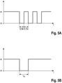
- FIG. 11 shows a diagram which illustrates a time sequence of a signal for controlling the lighting by the lighting device 32.
- the switched-on lighting of the lighting device 32 is denoted by e
- switched-off lighting is denoted by a. Following the chronological sequence, it can be seen that the lighting is initially switched on and then switched off or on again three times every 0.5 seconds. The lighting is then switched on again continuously.
- the continuous lighting at the beginning and end of the time sequence represents the normal operating mode.
- the area recognizable by the clocked (repeated) switching on and off represents the second signal operating mode.
- the control device 68 operates the lighting device in the normal operating mode when the workpiece sensors of the machine tool are not working detect in the workpiece holder. If, on the other hand, the workpiece sensors detect a workpiece in the workpiece holder, the normal operating mode is ended and replaced by a first signal operating mode. If the workpiece sensors continue to detect an incorrect fit of the workpiece, the control device 68 sets the second signal operating mode.
- FIG. 11 shows a further diagram which likewise illustrates a time pattern of a signal sequence for controlling the lighting by the lighting device 32.
- This flow chart shows that after some time the lighting is switched off once (for about one second). The lighting is then switched on again.
- the one-time switching off of the lighting device represents the first signal operating mode.
- the control device 68 sets this first signal operating mode when a workpiece has been correctly received in the workpiece holder.
- the in Figures 5A and 5B The operating modes of the lighting device shown here can easily be recognized by the worker in which state the workpiece is in the workpiece holder.
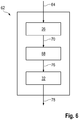
- Fig. 6 shows a block diagram of an exemplary embodiment of a monitoring device 62.
- the device 62 comprises a workpiece sensor 26, an (electronic) control device 68 and a lighting device 32.
- the workpiece sensor 26 is designed to detect an ambient signal.
- the workpiece sensor can be a pressure sensor, for example a dynamic pressure sensor, which is designed to receive a pressure signal.
- the workpiece sensor 26 can be a light sensor (light barrier, etc.) which is designed to receive a light signal.
- Other types of sensors are conceivable. Different types of sensors can be combined with one another.
- the workpiece sensor 26 provides the recorded ambient signal 64 as a monitoring signal 70 to the control device 68.
- the control device 68 evaluates the monitoring signal 70 off.
- a corresponding control signal 76 is passed on to the lighting device 32, which is responsible for controlling the lighting 78 of a work area of a machine tool.
- the correct mounting of a workpiece that is to say the correct placement of a workpiece mounting, can be acknowledged.
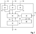
- Fig. 7 shows a block diagram of a further exemplary embodiment of the device 62.
- this embodiment of the device 62 also has an input unit 80 and a memory unit 82.
- Each of the workpiece sensors 26, 28, 30 is designed to detect a respective status signal 64, 66 and 68 and to convert it into a monitoring signal 70, 72, 74.
- the control device 68 receives these monitoring signals 70, 72, 74.
- the control device 68 is designed to receive an operator input / operator selection 84. This is done either directly via the input unit 18 or via the storage unit 82.
- Reference values for the measurement of the workpiece sensors for example pressure measurements for pressure sensors, but also settings that relate to the number or design of the operating modes of the lighting device can be considered as input signals.
- control device 68 All data are then evaluated by the control device 68 and the lighting device 32 or its lighting 78 is controlled with the aid of a control signal 76 in order to acknowledge the loading / equipping of the workpiece holder.
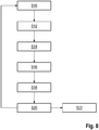
- FIG. 3 shows a block diagram to illustrate an exemplary embodiment of a method for monitoring a pick-up status of a workpiece in a machine tool.
- a lighting device is initially operated in a normal operating mode in order to illuminate a work area of the machine tool.
- a further step S12 comprises introducing a workpiece into a Workpiece holder of a machine tool.
- a further step S14 comprises a recording of a recording status of the workpiece in the workpiece holder with a workpiece sensor.
- the workpiece sensor then provides a monitoring signal which describes the recording status of the workpiece.
- the monitoring signal is evaluated in step S18.
- a certain operating mode can be selected for the lighting device in order to enable optical feedback / acknowledgment already in the work area. You can choose between a normal operating mode and a (first) signal operating mode. The signal operating mode is selected when a workpiece has been correctly inserted into the workpiece holder.
- step S22 the lighting device is then operated in the signal operating mode in order to acknowledge the correct recording. Otherwise, the normal operating mode is retained until the workpiece has been correctly received in the workpiece holder.
- the method can begin again with step S10.
Landscapes
- Engineering & Computer Science (AREA)
- Human Computer Interaction (AREA)
- Manufacturing & Machinery (AREA)
- Physics & Mathematics (AREA)
- General Physics & Mathematics (AREA)
- Automation & Control Theory (AREA)
- Mechanical Engineering (AREA)
- Auxiliary Devices For Machine Tools (AREA)
- Numerical Control (AREA)
- Machine Tool Sensing Apparatuses (AREA)
Priority Applications (1)
| Application Number | Priority Date | Filing Date | Title |
|---|---|---|---|
| PL19178779T PL3578294T3 (pl) | 2018-06-08 | 2019-06-06 | Urządzenie i sposób monitorowania stanu umocowania obrabianego przedmiotu |
Applications Claiming Priority (1)
| Application Number | Priority Date | Filing Date | Title |
|---|---|---|---|
| DE102018113741.9A DE102018113741A1 (de) | 2018-06-08 | 2018-06-08 | Vorrichtung und Verfahren zur Überwachung eines Aufnahmestatus eines Werkstücks |
Publications (2)
| Publication Number | Publication Date |
|---|---|
| EP3578294A1 EP3578294A1 (de) | 2019-12-11 |
| EP3578294B1 true EP3578294B1 (de) | 2021-03-17 |
Family
ID=66776226
Family Applications (1)
| Application Number | Title | Priority Date | Filing Date |
|---|---|---|---|
| EP19178779.5A Active EP3578294B1 (de) | 2018-06-08 | 2019-06-06 | Vorrichtung und verfahren zur überwachung eines aufnahmestatus eines werkstücks |
Country Status (5)
| Country | Link |
|---|---|
| US (1) | US11215965B2 (pl) |
| EP (1) | EP3578294B1 (pl) |
| DE (1) | DE102018113741A1 (pl) |
| ES (1) | ES2858399T3 (pl) |
| PL (1) | PL3578294T3 (pl) |
Families Citing this family (3)
| Publication number | Priority date | Publication date | Assignee | Title |
|---|---|---|---|---|
| US10792736B1 (en) * | 2018-05-26 | 2020-10-06 | Kitagawa-Northtech, Inc. | Lightweight intelligent top-tooling apparatus |
| EP4147820A1 (de) * | 2021-09-13 | 2023-03-15 | SMW-AUTOBLOK Spannsysteme GmbH | Spannvorrichtung |
| CN115070427A (zh) * | 2022-08-09 | 2022-09-20 | 浙江汉和智能装备有限公司 | 全自动打孔攻丝机 |
Family Cites Families (11)
| Publication number | Priority date | Publication date | Assignee | Title |
|---|---|---|---|---|
| US4254676A (en) * | 1977-10-29 | 1981-03-10 | Pratt Burnerd International Limited | Workholding |
| DE102005002448B4 (de) * | 2005-01-18 | 2010-04-22 | F.A.T. Fluide-Anwendungs-Technik Gmbh & Co. Kg | Vorrichtung und Verfahren zum Messen, Steuern oder Prüfen |
| DE102008014869A1 (de) * | 2008-03-18 | 2009-09-24 | Holzma Plattenaufteiltechnik Gmbh | Verfahren zum Betreiben einer Plattenaufteilanlage |
| JP5346726B2 (ja) * | 2009-07-24 | 2013-11-20 | 株式会社キーエンス | 連設型センサシステム、ネットワークユニット、及びセンサユニット |
| DE102009038046B4 (de) * | 2009-08-19 | 2014-07-31 | Ott-Jakob Spanntechnik Gmbh | Messvorrichtung zur Messung der Spannkraft an einer Werkzeugspannvorrichtung |
| JP2012053509A (ja) * | 2010-08-31 | 2012-03-15 | Mitsubishi Heavy Ind Ltd | 数値制御工作機械 |
| US9573215B2 (en) * | 2012-02-10 | 2017-02-21 | Illinois Tool Works Inc. | Sound-based weld travel speed sensing system and method |
| DE102013106226B4 (de) | 2013-06-14 | 2015-07-02 | Frank Entzmann | Vorrichtung und Verfahren zur Überwachung einer Werkstückspannvorrichtung |
| JP6492502B2 (ja) | 2014-10-03 | 2019-04-03 | 株式会社ジェイテクト | 工作機械の主軸装置 |
| US10593230B2 (en) * | 2015-08-12 | 2020-03-17 | Illinois Tool Works Inc. | Stick welding electrode holder systems and methods |
| EP3529675B1 (de) * | 2016-10-21 | 2022-12-14 | Trumpf Werkzeugmaschinen GmbH + Co. KG | Innenraum-personenortung-basierte fertigungssteuerung in der metallverarbeitenden industrie |
-
2018
- 2018-06-08 DE DE102018113741.9A patent/DE102018113741A1/de not_active Withdrawn
-
2019
- 2019-06-06 ES ES19178779T patent/ES2858399T3/es active Active
- 2019-06-06 EP EP19178779.5A patent/EP3578294B1/de active Active
- 2019-06-06 PL PL19178779T patent/PL3578294T3/pl unknown
- 2019-06-07 US US16/434,374 patent/US11215965B2/en active Active
Non-Patent Citations (1)
| Title |
|---|
| None * |
Also Published As
| Publication number | Publication date |
|---|---|
| EP3578294A1 (de) | 2019-12-11 |
| DE102018113741A1 (de) | 2019-12-12 |
| US20190377320A1 (en) | 2019-12-12 |
| PL3578294T3 (pl) | 2021-09-20 |
| ES2858399T3 (es) | 2021-09-30 |
| US11215965B2 (en) | 2022-01-04 |
Similar Documents
| Publication | Publication Date | Title |
|---|---|---|
| DE68916463T2 (de) | Signalübertragungssystem für Werkzeugmaschinen, Inspektionsmaschinen und dergleichen. | |
| EP2072180B1 (de) | Verfahren zur Montage einer Baugruppe | |
| EP3283256B1 (de) | Sensorisch überwachter blocksauger | |
| EP1346205B1 (de) | Verfahren und vorrichtung zur optischen inspektion von flaschen | |
| AT518362B1 (de) | Steuerungssystem für elektrisch gesteuerte Anlagen | |
| EP2216144A2 (de) | Verfahren und System zur Kontrolle von Bauteilen und/oder Funktionseinheiten mit einer Prüfvorrichtung | |
| EP2434842B1 (de) | Verfahren zur Lokalisierung von Lichtquellen, Computerprogramm und Lokalisierungseinheit | |
| DE102008019191A1 (de) | Vorrichtung und Verfahren zur gleichmäßigen Ausleuchtung eines Operationsfeldes | |
| EP3578294A1 (de) | Vorrichtung und verfahren zur überwachung eines aufnahmestatus eines werkstücks | |
| EP3417465B1 (de) | Steuerungssystem für elektrisch gesteuerte anlagen | |
| DE69230376T2 (de) | Verfahren und gerät zum sichern der korrekten bearbeitung einer folie | |
| WO2014095176A1 (de) | Verfahren und einrichtung zur funktionsprüfung von leuchtmitteln | |
| DE102013106226A1 (de) | Vorrichtung und Verfahren zur Überwachung einer Werkstückspannvorrichtung | |
| DE69429504T2 (de) | Verbesserung für auf eine sensorik basierende montagewerkzeuge | |
| EP2080585B1 (de) | Überwachungsvorrichtung | |
| EP3670073B1 (de) | Spannvorrichtung | |
| DE102018113989B4 (de) | Fertigungsvorrichtung und verfahren | |
| EP0223076B1 (de) | Vollautomatisches Robotersystem | |
| DE102016213198B4 (de) | Anschlagvorrichtung | |
| DE112018000668T5 (de) | Vorrichtung und Verfahren zur Fehlerdiagnose | |
| EP3424275B1 (de) | Verfahren und vorrichtung zum automatischen erfassen der konfiguration von hintereinander geschaltenen leuchtelementen | |
| DE4037904A1 (de) | Vorrichtung zum entfernen von fehlerhaft eingesetzten teilen in einer automatischen einsetzmaschine | |
| DE68919800T2 (de) | Methode zur Diagnose von Folgeprogrammen, verwendbar in einer Folgesteuerungsanlage. | |
| DE102024139067B3 (de) | Robotersystem zur Benutzerführung | |
| DE19801764C2 (de) | Verfahren zum Bestimmen und Korrigieren der Zentrizitäts- bzw. der Lageabweichungen von Werkstücken sowie Vorrichtung zur Durchführung desselben |
Legal Events
| Date | Code | Title | Description |
|---|---|---|---|
| PUAI | Public reference made under article 153(3) epc to a published international application that has entered the european phase |
Free format text: ORIGINAL CODE: 0009012 |
|
| STAA | Information on the status of an ep patent application or granted ep patent |
Free format text: STATUS: THE APPLICATION HAS BEEN PUBLISHED |
|
| AK | Designated contracting states |
Kind code of ref document: A1 Designated state(s): AL AT BE BG CH CY CZ DE DK EE ES FI FR GB GR HR HU IE IS IT LI LT LU LV MC MK MT NL NO PL PT RO RS SE SI SK SM TR |
|
| AX | Request for extension of the european patent |
Extension state: BA ME |
|
| STAA | Information on the status of an ep patent application or granted ep patent |
Free format text: STATUS: REQUEST FOR EXAMINATION WAS MADE |
|
| 17P | Request for examination filed |
Effective date: 20200330 |
|
| RBV | Designated contracting states (corrected) |
Designated state(s): AL AT BE BG CH CY CZ DE DK EE ES FI FR GB GR HR HU IE IS IT LI LT LU LV MC MK MT NL NO PL PT RO RS SE SI SK SM TR |
|
| RIC1 | Information provided on ipc code assigned before grant |
Ipc: B23Q 17/24 20060101ALI20200716BHEP Ipc: B23Q 17/00 20060101AFI20200716BHEP |
|
| GRAP | Despatch of communication of intention to grant a patent |
Free format text: ORIGINAL CODE: EPIDOSNIGR1 |
|
| STAA | Information on the status of an ep patent application or granted ep patent |
Free format text: STATUS: GRANT OF PATENT IS INTENDED |
|
| INTG | Intention to grant announced |
Effective date: 20200921 |
|
| GRAS | Grant fee paid |
Free format text: ORIGINAL CODE: EPIDOSNIGR3 |
|
| GRAA | (expected) grant |
Free format text: ORIGINAL CODE: 0009210 |
|
| STAA | Information on the status of an ep patent application or granted ep patent |
Free format text: STATUS: THE PATENT HAS BEEN GRANTED |
|
| RAP1 | Party data changed (applicant data changed or rights of an application transferred) |
Owner name: CHIRON GROUP SE |
|
| AK | Designated contracting states |
Kind code of ref document: B1 Designated state(s): AL AT BE BG CH CY CZ DE DK EE ES FI FR GB GR HR HU IE IS IT LI LT LU LV MC MK MT NL NO PL PT RO RS SE SI SK SM TR |
|
| REG | Reference to a national code |
Ref country code: GB Ref legal event code: FG4D Free format text: NOT ENGLISH |
|
| REG | Reference to a national code |
Ref country code: CH Ref legal event code: EP Ref country code: CH Ref legal event code: NV Representative=s name: RENTSCH PARTNER AG, CH |
|
| REG | Reference to a national code |
Ref country code: DE Ref legal event code: R096 Ref document number: 502019001004 Country of ref document: DE |
|
| REG | Reference to a national code |
Ref country code: IE Ref legal event code: FG4D Free format text: LANGUAGE OF EP DOCUMENT: GERMAN |
|
| REG | Reference to a national code |
Ref country code: AT Ref legal event code: REF Ref document number: 1371794 Country of ref document: AT Kind code of ref document: T Effective date: 20210415 |
|
| REG | Reference to a national code |
Ref country code: LT Ref legal event code: MG9D |
|
| PG25 | Lapsed in a contracting state [announced via postgrant information from national office to epo] |
Ref country code: NO Free format text: LAPSE BECAUSE OF FAILURE TO SUBMIT A TRANSLATION OF THE DESCRIPTION OR TO PAY THE FEE WITHIN THE PRESCRIBED TIME-LIMIT Effective date: 20210617 Ref country code: BG Free format text: LAPSE BECAUSE OF FAILURE TO SUBMIT A TRANSLATION OF THE DESCRIPTION OR TO PAY THE FEE WITHIN THE PRESCRIBED TIME-LIMIT Effective date: 20210617 Ref country code: HR Free format text: LAPSE BECAUSE OF FAILURE TO SUBMIT A TRANSLATION OF THE DESCRIPTION OR TO PAY THE FEE WITHIN THE PRESCRIBED TIME-LIMIT Effective date: 20210317 Ref country code: GR Free format text: LAPSE BECAUSE OF FAILURE TO SUBMIT A TRANSLATION OF THE DESCRIPTION OR TO PAY THE FEE WITHIN THE PRESCRIBED TIME-LIMIT Effective date: 20210618 Ref country code: FI Free format text: LAPSE BECAUSE OF FAILURE TO SUBMIT A TRANSLATION OF THE DESCRIPTION OR TO PAY THE FEE WITHIN THE PRESCRIBED TIME-LIMIT Effective date: 20210317 |
|
| REG | Reference to a national code |
Ref country code: NL Ref legal event code: MP Effective date: 20210317 |
|
| PG25 | Lapsed in a contracting state [announced via postgrant information from national office to epo] |
Ref country code: RS Free format text: LAPSE BECAUSE OF FAILURE TO SUBMIT A TRANSLATION OF THE DESCRIPTION OR TO PAY THE FEE WITHIN THE PRESCRIBED TIME-LIMIT Effective date: 20210317 Ref country code: SE Free format text: LAPSE BECAUSE OF FAILURE TO SUBMIT A TRANSLATION OF THE DESCRIPTION OR TO PAY THE FEE WITHIN THE PRESCRIBED TIME-LIMIT Effective date: 20210317 Ref country code: LV Free format text: LAPSE BECAUSE OF FAILURE TO SUBMIT A TRANSLATION OF THE DESCRIPTION OR TO PAY THE FEE WITHIN THE PRESCRIBED TIME-LIMIT Effective date: 20210317 |
|
| PG25 | Lapsed in a contracting state [announced via postgrant information from national office to epo] |
Ref country code: NL Free format text: LAPSE BECAUSE OF FAILURE TO SUBMIT A TRANSLATION OF THE DESCRIPTION OR TO PAY THE FEE WITHIN THE PRESCRIBED TIME-LIMIT Effective date: 20210317 |
|
| REG | Reference to a national code |
Ref country code: ES Ref legal event code: FG2A Ref document number: 2858399 Country of ref document: ES Kind code of ref document: T3 Effective date: 20210930 |
|
| PG25 | Lapsed in a contracting state [announced via postgrant information from national office to epo] |
Ref country code: LT Free format text: LAPSE BECAUSE OF FAILURE TO SUBMIT A TRANSLATION OF THE DESCRIPTION OR TO PAY THE FEE WITHIN THE PRESCRIBED TIME-LIMIT Effective date: 20210317 Ref country code: CZ Free format text: LAPSE BECAUSE OF FAILURE TO SUBMIT A TRANSLATION OF THE DESCRIPTION OR TO PAY THE FEE WITHIN THE PRESCRIBED TIME-LIMIT Effective date: 20210317 Ref country code: EE Free format text: LAPSE BECAUSE OF FAILURE TO SUBMIT A TRANSLATION OF THE DESCRIPTION OR TO PAY THE FEE WITHIN THE PRESCRIBED TIME-LIMIT Effective date: 20210317 Ref country code: SM Free format text: LAPSE BECAUSE OF FAILURE TO SUBMIT A TRANSLATION OF THE DESCRIPTION OR TO PAY THE FEE WITHIN THE PRESCRIBED TIME-LIMIT Effective date: 20210317 |
|
| PG25 | Lapsed in a contracting state [announced via postgrant information from national office to epo] |
Ref country code: SK Free format text: LAPSE BECAUSE OF FAILURE TO SUBMIT A TRANSLATION OF THE DESCRIPTION OR TO PAY THE FEE WITHIN THE PRESCRIBED TIME-LIMIT Effective date: 20210317 Ref country code: PT Free format text: LAPSE BECAUSE OF FAILURE TO SUBMIT A TRANSLATION OF THE DESCRIPTION OR TO PAY THE FEE WITHIN THE PRESCRIBED TIME-LIMIT Effective date: 20210719 Ref country code: RO Free format text: LAPSE BECAUSE OF FAILURE TO SUBMIT A TRANSLATION OF THE DESCRIPTION OR TO PAY THE FEE WITHIN THE PRESCRIBED TIME-LIMIT Effective date: 20210317 Ref country code: IS Free format text: LAPSE BECAUSE OF FAILURE TO SUBMIT A TRANSLATION OF THE DESCRIPTION OR TO PAY THE FEE WITHIN THE PRESCRIBED TIME-LIMIT Effective date: 20210717 |
|
| REG | Reference to a national code |
Ref country code: DE Ref legal event code: R097 Ref document number: 502019001004 Country of ref document: DE |
|
| PLBE | No opposition filed within time limit |
Free format text: ORIGINAL CODE: 0009261 |
|
| STAA | Information on the status of an ep patent application or granted ep patent |
Free format text: STATUS: NO OPPOSITION FILED WITHIN TIME LIMIT |
|
| PG25 | Lapsed in a contracting state [announced via postgrant information from national office to epo] |
Ref country code: AL Free format text: LAPSE BECAUSE OF FAILURE TO SUBMIT A TRANSLATION OF THE DESCRIPTION OR TO PAY THE FEE WITHIN THE PRESCRIBED TIME-LIMIT Effective date: 20210317 Ref country code: DK Free format text: LAPSE BECAUSE OF FAILURE TO SUBMIT A TRANSLATION OF THE DESCRIPTION OR TO PAY THE FEE WITHIN THE PRESCRIBED TIME-LIMIT Effective date: 20210317 Ref country code: MC Free format text: LAPSE BECAUSE OF FAILURE TO SUBMIT A TRANSLATION OF THE DESCRIPTION OR TO PAY THE FEE WITHIN THE PRESCRIBED TIME-LIMIT Effective date: 20210317 |
|
| 26N | No opposition filed |
Effective date: 20211220 |
|
| PG25 | Lapsed in a contracting state [announced via postgrant information from national office to epo] |
Ref country code: SI Free format text: LAPSE BECAUSE OF FAILURE TO SUBMIT A TRANSLATION OF THE DESCRIPTION OR TO PAY THE FEE WITHIN THE PRESCRIBED TIME-LIMIT Effective date: 20210317 |
|
| REG | Reference to a national code |
Ref country code: BE Ref legal event code: MM Effective date: 20210630 |
|
| PG25 | Lapsed in a contracting state [announced via postgrant information from national office to epo] |
Ref country code: LU Free format text: LAPSE BECAUSE OF NON-PAYMENT OF DUE FEES Effective date: 20210606 |
|
| PG25 | Lapsed in a contracting state [announced via postgrant information from national office to epo] |
Ref country code: IE Free format text: LAPSE BECAUSE OF NON-PAYMENT OF DUE FEES Effective date: 20210606 |
|
| PG25 | Lapsed in a contracting state [announced via postgrant information from national office to epo] |
Ref country code: IS Free format text: LAPSE BECAUSE OF FAILURE TO SUBMIT A TRANSLATION OF THE DESCRIPTION OR TO PAY THE FEE WITHIN THE PRESCRIBED TIME-LIMIT Effective date: 20210717 Ref country code: FR Free format text: LAPSE BECAUSE OF NON-PAYMENT OF DUE FEES Effective date: 20210630 |
|
| PG25 | Lapsed in a contracting state [announced via postgrant information from national office to epo] |
Ref country code: BE Free format text: LAPSE BECAUSE OF NON-PAYMENT OF DUE FEES Effective date: 20210630 |
|
| PG25 | Lapsed in a contracting state [announced via postgrant information from national office to epo] |
Ref country code: CY Free format text: LAPSE BECAUSE OF FAILURE TO SUBMIT A TRANSLATION OF THE DESCRIPTION OR TO PAY THE FEE WITHIN THE PRESCRIBED TIME-LIMIT Effective date: 20210317 |
|
| PG25 | Lapsed in a contracting state [announced via postgrant information from national office to epo] |
Ref country code: HU Free format text: LAPSE BECAUSE OF FAILURE TO SUBMIT A TRANSLATION OF THE DESCRIPTION OR TO PAY THE FEE WITHIN THE PRESCRIBED TIME-LIMIT; INVALID AB INITIO Effective date: 20190606 |
|
| PGFP | Annual fee paid to national office [announced via postgrant information from national office to epo] |
Ref country code: PL Payment date: 20230601 Year of fee payment: 5 |
|
| PGFP | Annual fee paid to national office [announced via postgrant information from national office to epo] |
Ref country code: IT Payment date: 20230623 Year of fee payment: 5 Ref country code: ES Payment date: 20230830 Year of fee payment: 5 Ref country code: CH Payment date: 20230702 Year of fee payment: 5 |
|
| GBPC | Gb: european patent ceased through non-payment of renewal fee |
Effective date: 20230606 |
|
| PG25 | Lapsed in a contracting state [announced via postgrant information from national office to epo] |
Ref country code: MK Free format text: LAPSE BECAUSE OF FAILURE TO SUBMIT A TRANSLATION OF THE DESCRIPTION OR TO PAY THE FEE WITHIN THE PRESCRIBED TIME-LIMIT Effective date: 20210317 Ref country code: GB Free format text: LAPSE BECAUSE OF NON-PAYMENT OF DUE FEES Effective date: 20230606 |
|
| PG25 | Lapsed in a contracting state [announced via postgrant information from national office to epo] |
Ref country code: MT Free format text: LAPSE BECAUSE OF FAILURE TO SUBMIT A TRANSLATION OF THE DESCRIPTION OR TO PAY THE FEE WITHIN THE PRESCRIBED TIME-LIMIT Effective date: 20210317 |
|
| REG | Reference to a national code |
Ref country code: CH Ref legal event code: PL |
|
| PG25 | Lapsed in a contracting state [announced via postgrant information from national office to epo] |
Ref country code: CH Free format text: LAPSE BECAUSE OF NON-PAYMENT OF DUE FEES Effective date: 20240630 |
|
| PG25 | Lapsed in a contracting state [announced via postgrant information from national office to epo] |
Ref country code: IT Free format text: LAPSE BECAUSE OF NON-PAYMENT OF DUE FEES Effective date: 20240606 |
|
| REG | Reference to a national code |
Ref country code: ES Ref legal event code: FD2A Effective date: 20250728 |
|
| REG | Reference to a national code |
Ref country code: AT Ref legal event code: MM01 Ref document number: 1371794 Country of ref document: AT Kind code of ref document: T Effective date: 20240606 |
|
| PG25 | Lapsed in a contracting state [announced via postgrant information from national office to epo] |
Ref country code: ES Free format text: LAPSE BECAUSE OF NON-PAYMENT OF DUE FEES Effective date: 20240607 |
|
| PGFP | Annual fee paid to national office [announced via postgrant information from national office to epo] |
Ref country code: DE Payment date: 20250730 Year of fee payment: 7 |
|
| PG25 | Lapsed in a contracting state [announced via postgrant information from national office to epo] |
Ref country code: PL Free format text: LAPSE BECAUSE OF NON-PAYMENT OF DUE FEES Effective date: 20240606 |
|
| PG25 | Lapsed in a contracting state [announced via postgrant information from national office to epo] |
Ref country code: AT Free format text: LAPSE BECAUSE OF NON-PAYMENT OF DUE FEES Effective date: 20240606 |
|
| PG25 | Lapsed in a contracting state [announced via postgrant information from national office to epo] |
Ref country code: TR Free format text: LAPSE BECAUSE OF FAILURE TO SUBMIT A TRANSLATION OF THE DESCRIPTION OR TO PAY THE FEE WITHIN THE PRESCRIBED TIME-LIMIT Effective date: 20210317 |
|
| PGFP | Annual fee paid to national office [announced via postgrant information from national office to epo] |
Ref country code: AT Payment date: 20260410 Year of fee payment: 5 |