EP3578294A1 - Device and method for monitoring a holding status of a workpiece - Google Patents
Device and method for monitoring a holding status of a workpiece Download PDFInfo
- Publication number
- EP3578294A1 EP3578294A1 EP19178779.5A EP19178779A EP3578294A1 EP 3578294 A1 EP3578294 A1 EP 3578294A1 EP 19178779 A EP19178779 A EP 19178779A EP 3578294 A1 EP3578294 A1 EP 3578294A1
- Authority
- EP
- European Patent Office
- Prior art keywords
- workpiece
- operating mode
- state
- working space
- signal
- Prior art date
- Legal status (The legal status is an assumption and is not a legal conclusion. Google has not performed a legal analysis and makes no representation as to the accuracy of the status listed.)
- Granted
Links
- 238000012544 monitoring process Methods 0.000 title claims abstract description 41
- 238000000034 method Methods 0.000 title claims abstract description 15
- 238000005286 illumination Methods 0.000 claims abstract description 80
- 238000012806 monitoring device Methods 0.000 claims abstract description 10
- 230000000007 visual effect Effects 0.000 claims abstract description 7
- 230000008859 change Effects 0.000 claims description 9
- 230000003287 optical effect Effects 0.000 claims description 4
- 238000006073 displacement reaction Methods 0.000 claims description 2
- 230000001939 inductive effect Effects 0.000 claims description 2
- 230000003213 activating effect Effects 0.000 claims 1
- 238000003754 machining Methods 0.000 description 12
- 238000010586 diagram Methods 0.000 description 8
- 238000011156 evaluation Methods 0.000 description 7
- 238000012545 processing Methods 0.000 description 6
- 108010076504 Protein Sorting Signals Proteins 0.000 description 5
- 230000004888 barrier function Effects 0.000 description 5
- 230000002123 temporal effect Effects 0.000 description 5
- 230000009849 deactivation Effects 0.000 description 4
- 238000005303 weighing Methods 0.000 description 4
- 230000004913 activation Effects 0.000 description 3
- 238000003801 milling Methods 0.000 description 3
- 230000001681 protective effect Effects 0.000 description 3
- 230000011664 signaling Effects 0.000 description 3
- 230000008901 benefit Effects 0.000 description 2
- 238000013461 design Methods 0.000 description 2
- 230000007613 environmental effect Effects 0.000 description 2
- 238000004519 manufacturing process Methods 0.000 description 2
- 238000005259 measurement Methods 0.000 description 2
- 230000008569 process Effects 0.000 description 2
- 230000004044 response Effects 0.000 description 2
- DGAQECJNVWCQMB-PUAWFVPOSA-M Ilexoside XXIX Chemical compound C[C@@H]1CC[C@@]2(CC[C@@]3(C(=CC[C@H]4[C@]3(CC[C@@H]5[C@@]4(CC[C@@H](C5(C)C)OS(=O)(=O)[O-])C)C)[C@@H]2[C@]1(C)O)C)C(=O)O[C@H]6[C@@H]([C@H]([C@@H]([C@H](O6)CO)O)O)O.[Na+] DGAQECJNVWCQMB-PUAWFVPOSA-M 0.000 description 1
- 230000005540 biological transmission Effects 0.000 description 1
- 230000004397 blinking Effects 0.000 description 1
- 230000000052 comparative effect Effects 0.000 description 1
- 238000012790 confirmation Methods 0.000 description 1
- 238000012937 correction Methods 0.000 description 1
- 238000001514 detection method Methods 0.000 description 1
- 238000009826 distribution Methods 0.000 description 1
- 230000000694 effects Effects 0.000 description 1
- 230000006870 function Effects 0.000 description 1
- 229910052736 halogen Inorganic materials 0.000 description 1
- 150000002367 halogens Chemical class 0.000 description 1
- 238000010438 heat treatment Methods 0.000 description 1
- 238000003780 insertion Methods 0.000 description 1
- 230000037431 insertion Effects 0.000 description 1
- 238000002955 isolation Methods 0.000 description 1
- 238000012423 maintenance Methods 0.000 description 1
- 230000007257 malfunction Effects 0.000 description 1
- 239000002184 metal Substances 0.000 description 1
- 229910052751 metal Inorganic materials 0.000 description 1
- 150000002739 metals Chemical class 0.000 description 1
- 230000007935 neutral effect Effects 0.000 description 1
- 230000010349 pulsation Effects 0.000 description 1
- 238000009420 retrofitting Methods 0.000 description 1
- 229910052708 sodium Inorganic materials 0.000 description 1
- 239000011734 sodium Substances 0.000 description 1
- 239000011343 solid material Substances 0.000 description 1
- 230000003319 supportive effect Effects 0.000 description 1
- 238000012360 testing method Methods 0.000 description 1
- 238000012549 training Methods 0.000 description 1
Images


Classifications
-
- B—PERFORMING OPERATIONS; TRANSPORTING
- B23—MACHINE TOOLS; METAL-WORKING NOT OTHERWISE PROVIDED FOR
- B23Q—DETAILS, COMPONENTS, OR ACCESSORIES FOR MACHINE TOOLS, e.g. ARRANGEMENTS FOR COPYING OR CONTROLLING; MACHINE TOOLS IN GENERAL CHARACTERISED BY THE CONSTRUCTION OF PARTICULAR DETAILS OR COMPONENTS; COMBINATIONS OR ASSOCIATIONS OF METAL-WORKING MACHINES, NOT DIRECTED TO A PARTICULAR RESULT
- B23Q17/00—Arrangements for observing, indicating or measuring on machine tools
- B23Q17/006—Arrangements for observing, indicating or measuring on machine tools for indicating the presence of a work or tool in its holder
-
- G—PHYSICS
- G05—CONTROLLING; REGULATING
- G05B—CONTROL OR REGULATING SYSTEMS IN GENERAL; FUNCTIONAL ELEMENTS OF SUCH SYSTEMS; MONITORING OR TESTING ARRANGEMENTS FOR SUCH SYSTEMS OR ELEMENTS
- G05B19/00—Programme-control systems
- G05B19/02—Programme-control systems electric
- G05B19/18—Numerical control [NC], i.e. automatically operating machines, in particular machine tools, e.g. in a manufacturing environment, so as to execute positioning, movement or co-ordinated operations by means of programme data in numerical form
- G05B19/402—Numerical control [NC], i.e. automatically operating machines, in particular machine tools, e.g. in a manufacturing environment, so as to execute positioning, movement or co-ordinated operations by means of programme data in numerical form characterised by control arrangements for positioning, e.g. centring a tool relative to a hole in the workpiece, additional detection means to correct position
-
- B—PERFORMING OPERATIONS; TRANSPORTING
- B23—MACHINE TOOLS; METAL-WORKING NOT OTHERWISE PROVIDED FOR
- B23Q—DETAILS, COMPONENTS, OR ACCESSORIES FOR MACHINE TOOLS, e.g. ARRANGEMENTS FOR COPYING OR CONTROLLING; MACHINE TOOLS IN GENERAL CHARACTERISED BY THE CONSTRUCTION OF PARTICULAR DETAILS OR COMPONENTS; COMBINATIONS OR ASSOCIATIONS OF METAL-WORKING MACHINES, NOT DIRECTED TO A PARTICULAR RESULT
- B23Q17/00—Arrangements for observing, indicating or measuring on machine tools
- B23Q17/24—Arrangements for observing, indicating or measuring on machine tools using optics or electromagnetic waves
- B23Q17/2433—Detection of presence or absence
- B23Q17/2447—Detection of presence or absence of a workpiece
-
- G—PHYSICS
- G05—CONTROLLING; REGULATING
- G05B—CONTROL OR REGULATING SYSTEMS IN GENERAL; FUNCTIONAL ELEMENTS OF SUCH SYSTEMS; MONITORING OR TESTING ARRANGEMENTS FOR SUCH SYSTEMS OR ELEMENTS
- G05B2219/00—Program-control systems
- G05B2219/30—Nc systems
- G05B2219/37—Measurements
- G05B2219/37002—Absence, detect absence, presence or correct position of workpiece
Definitions
- the present disclosure relates to an apparatus for monitoring a picking status of a workpiece in a machine tool or a defined environment of a machine tool. Further, the present disclosure relates to a machine tool having such a device, a method for monitoring a pickup status and a corresponding machine control program.
- Devices of the aforementioned type are well known. They are often used in machine tools for machining metals or solid materials, especially in CNC machine tools. With the help of such devices can be distinguished whether there is a workpiece in the machine tool or an associated environment or not. Furthermore, it can be ensured be that a workpiece is in a required position for its processing.
- the check of the recording status is done via a sensor.
- the sensors used are usually compressed air or dynamic pressure sensors which scan the workpiece (or the space provided for the workpiece) with an air jet from a sensor nozzle.
- By a subsequent evaluation of the resulting back pressure can be taken, among other things, a statement about the presence and / or position of a workpiece in a workpiece holder. If the workpiece is picked up as intended, corresponding measured values for the measured back pressure result. On the other hand, if the workpiece is positioned incorrectly, deviating knife values will be displayed indicating the incorrect fit.
- the machine tools are loaded manually.
- the operator or the worker is responsible for ensuring that the workpiece is received in the machine tool as intended.
- a corresponding supportive condition monitoring of the workpiece is therefore helpful if precise production and low-error operation are to be ensured.
- a method for operating a panel-forming machine for large-format panels wherein a workpiece is manually handled by a person in a handling area, information and / or instructions for manual handling of the workpiece being output to the person by means of an information device located in the handling area and the handling information is output to the person depending on data provided by the workpiece detection device.
- the information device is designed as a laser projector. Thus, a separate device is used to provide information.
- a feedback on the recording status of the workpiece, so for example on its position, is usually done for the machine operator on a control panel on the outer shell of a machine tool.
- a machine tool and device for workpiece monitoring for example, from DE 10 2013 106 226 A1 known.
- the present disclosure has the object, training monitoring devices and machine tools provided therewith in order to simplify the assembly of workpieces. This should be achievable with the least possible additional effort.
- the monitoring device should help to minimize workpiece change times.
- the operator ergonomics should be improved as much as possible.
- the quality and accuracy of the processing and the reliability of the machine tool to be increased overall.
- the device for signaling / acknowledging the picking up status of a workpiece in the machine tool in fact falls back on the lighting device of the working space, which is already installed anyway.
- a signaling on a control panel on the outside of the machine tool can be dispensed with in the ideal case.
- the operator no longer has to move out of the working space / sit back. Instead, the operator or worker still receives information about the recording status in the working space of the machine tool and can react immediately and if necessary correct the seat of the workpiece.
- the workpiece change time can be reduced. The operator is protected from ergonomically unfavorable movements of his body.
- the monitoring device can acknowledge, for example, the correct seat of the workpiece directly in the working area via the illumination which is present there anyway.
- the acknowledgment takes place visually via light signals or light signals.
- the acknowledgment takes place, at least in exemplary embodiments, via the illumination of the working space, which is selectively activated via the control device.
- the lighting illuminates the working area in normal operating mode to provide good visibility.
- the illumination is used for information transmission in order to signal the operator / worker still in the work space whether the workpiece has been correctly placed or not.
- the device according to the above aspect offers the advantage that no new components (structural type) must be installed.
- the control device is designed to control the lighting device present in the working space and to give the operator or worker feedback about the picking status of the work piece via this lighting device.
- a signal output on the control panel is therefore no longer absolutely necessary, but can be done additionally. If necessary, even existing machine components, such as individual signal lights, can be dispensed with on the control panel.
- the device is suitable for retrofitting existing systems. These can be retrofitted in a simple manner.
- the actual state is a currently detected (real) state.
- the target state is a target state or a desired state. The conditions may arise with regard to the correct picking up of the workpiece in the workpiece holder. Then, the device can be used to determine whether the workpiece is correctly or possibly incorrectly recorded. This is reflected in the recording status again.
- the illumination device is, at least in exemplary embodiments, at least one light source, in particular a light source for generating polychromatic light, in particular an at least white light source.
- the illumination device is used for illuminating, in particular for illuminating the working space for the operator. This improves observability and monitorability.
- Light sources include, for example, incandescent lamps, halogen lamps, LED lamps, fluorescent lamps and high-pressure sodium vapor lamps.
- White light includes, for example, the emission of broadband light with a suitable color temperature, such as daylight white or neutral white. In general, a color temperature suitable for the application is selected.
- the above embodiment of the monitoring device is particularly suitable for the monitoring of workpieces, or of their receiving state in the working space of the machine tool.
- the device allows an ergonomically improved assembly process. To check the assembly, the worker no longer has to lean awkwardly out of the working space to detect an acknowledgment signal via a display or other display on the outside of the machine tool. Rather, the worker can now check the recording status of the workpiece directly during the assembly or his residence in the working space or operating space of the machine tool.
- the signals can be used, for example, to provide state histories using a memory and evaluation unit.
- the defined environment is, for example, a buffer store, an interchangeable receiving device which is temporarily arranged outside the working space, and / or a receptacle for the workpiece, a handling device which then loads the working space.
- the control device assigns the actual state to the first intake state when the actual state coincides with a desired state, and wherein the control device assigns the actual state to the second intake state if the actual state does not match the target State matches.
- a desired state for example, the correct recording of a workpiece is defined in a clamping nest. If the workpiece has the correct seat in the clamping nest, the actual state and target state match. The controller then assigns the current state to the first recording state. If, on the other hand, the seat is not correct because, for example, a clamping jaw does not grasp the workpiece correctly, an assignment to the second recording status takes place. This can also mean that the second recording status is selected if there is no workpiece at all in the workpiece holder.
- control device operates the illumination device in the signal operating mode if the actual state is associated with the first recording state or if the monitoring signal indicates that the workpiece is in the first recording state.
- the mode of Lighting device is thus converted from the normal operating mode only in the signal operating mode when the actual state of the workpiece coincides with the target state.
- the signal operating mode is activated only when the workpiece has been correctly placed with respect to all the fasteners provided.
- the lighting device is integrated into the working space.
- signals emitted by the illumination device are visible in the working space.
- the working space of a machine tool is already equipped with a lighting device that makes it easier for the worker to monitor the workpiece machining.
- a lighting of the work space by a lighting device outside the work space is conceivable, but here is often a disability of the worker given by shading effects.
- the illumination device is operable in a first signal operating mode and in a second signal operating mode, wherein the control device operates the illumination device in the first signal operating mode when the actual state is associated with the first recording state, and wherein the control device controls the illumination device in the second Signal operating mode operates when the current state is associated with the second recording status.
- the mode of the illumination device is changed over from the second to the first signal operating mode as soon as the actual state of the workpiece coincides with the desired state.
- the illumination device of the device is operated in the normal operating mode as long as there is no workpiece at all in the working space of the machine tool.
- Exemplary embodiments provide that the illumination device is operated in the second signal operating mode when the workpiece sensor detects a workpiece, but the workpiece is not yet in the desired state. If the operator has then brought the workpiece to the desired state, the mode of the illumination device is changed over again, in the first signal operating mode to acknowledge this.
- the illumination device is operable to output binary or three-stage signals over time.
- the illumination device may be activated for a first time duration and a second time duration, as well as being deactivated for a third time duration.
- the first time period is longer than the second time duration, and for example, the second time duration is longer than the third time duration.
- the illumination of the illumination device can thus be activated, for example, in the signal operating mode initially for five seconds, then deactivated for one second, activated again for 2.5 seconds and then deactivated again for one second.
- the three-stage operation corresponds to a Lichtmorse mode. Other signal sequences are conceivable.
- the signal operating mode of the device comprises a selective deactivation and / or activation of the illumination device. It is conceivable that the lighting device is activated continuously in the normal operating mode and is deactivated (at least for a short time) when changing to the signal operating mode.
- the duration of the illumination deactivation can in principle be arbitrary. However, only a short switch off and an early return to the normal mode of operation are advantageous, since the operator or worker then finds a virtually completely and permanently illuminated work space during workpiece machining.
- the signal operating mode can also include a repeated deactivation or activation of the illumination device (pulsating illumination). For example, the light may flash for a predefined time as soon as the intended recording status of the work piece has been reached.
- the signal operating mode comprises a change in illuminance and / or illumination color.
- the control device causes a brief change of the illumination color (For example, from white to green, or from red to green), when the desired recording status is reached and the lighting device is operated in the signal operating mode.
- the illuminance can be varied analogously to the activation / deactivation (single impulse or pulsation).
- the actual state comprises a state variable selected from the group consisting of: presence, absence, position, orientation, a clamping state of the workpiece, and any combinations thereof.
- the control device deduces from the monitoring signal provided by the at least one workpiece sensor, which describes the actual state of the workpiece, whether the workpiece was received in the correct position and orientation in the workpiece holder.
- the control device can be designed to detect on the basis of the monitoring signal whether a workpiece is clamped firmly enough.
- the at least one workpiece sensor is selected from the group consisting of: mechanical sensors, optical sensors, inductive sensors, electrical sensors, displacement sensors, pressure sensors, force sensors, and combinations thereof.
- the device further has an input unit that is configured to receive operator inputs / selections that are intended for the control device for controlling the illumination device.
- Operator input means, for example, a concrete selection relating to one or more temporal, spatial and / or colored signals or signal sequences for the acknowledgment or in general the response to the recording status.
- the user information may also include information as to whether the user, ie the operator, is in addition to the first signal operating mode wants a second signal operating mode (error indication). It is understood that the input unit can form part of the device, but can also be operated as a unit separate from the device.
- the control device is designed to control a lighting device in a loading area of a machine tool.
- the machine tool can be configured to selectively operate the illumination device in the loading area as a function of the monitoring signal provided by the at least one workpiece sensor in the signal operating mode in order to provide visual information in the loading area to illustrate the picking status of the workpiece.
- the lighting device in the working space or loading area is preferably one or more light-emitting diodes (LEDs).
- LEDs light-emitting diodes
- the comparatively long lifetime of LEDs offers low-maintenance lighting.
- the heating of LEDs during operation is of minor importance.
- Other technical solutions for light signaling can also be used.
- the machine tool is designed for example as a lathe, milling machine, laser machine (laser processing machine), and / or as a combined machine for turning, milling and / or laser machining.
- it is a so-called multi-axis machine with a plurality of controlled axes.
- the machine tool comprises an enclosure with a closable opening which allows access to the working space. In principle, however, it can also be other types and configurations of machine tools.
- the frame can also be referred to as a machine bed or executed.
- the object is further achieved by a machine control program having program code configured to cause a controller of a machine tool to execute the steps of the method according to an embodiment of the present disclosure when the machine control program is executed on the controller.
- Fig. 1 shows a perspective view of an exemplary embodiment of a machine tool 10.
- the machine tool 10 shown comprises a frame 12 which encloses a working space 14, wherein in the working space 14, a weighing plate 16 with a workpiece holder 18 for receiving a workpiece (in the Figures 3B-3C denoted by 50) is located. Furthermore, the machine tool 10 has a lighting device 32 and a control panel 34, which is located on the outside of the machine frame. In the illustrations in Fig. 1 . Fig. 2 , and Fig. 5 For illustrative reasons, no workpiece is shown.
- the workpiece holder 18 has, for example, three stops. The workpiece is then placed correctly in the workpiece holder 18 when certain abutment surfaces / contact points of the workpiece bear against the stops 20, 22 and 24. Whether the workpiece is correctly placed in the workpiece holder 18 is checked by means of three workpiece sensors 26, 28, 30 located at the bottom of the weighing plate 16. It is understood that in alternative embodiments, more or fewer workpiece sensors are installed in the workpiece holder 18.
- the workpiece sensors 26, 28, 30 in this exemplary embodiment are dynamic pressure sensors. By measuring nozzles, the environment of the sensors 26, 28, 30 is scanned. The resulting dynamic pressure gives indications of the presence, orientation and / or dimensional accuracy of an inserted workpiece. The measurements of the sensors 26, 28, 30 are transmitted as monitoring signals to the machine control.
- the machine control comprises, for example, a control device which in Fig. 1 is indicated by a designated 68 block.
- the machine control or the control device 68 of the machine tool 10 evaluates the monitoring signals. In particular, takes place in the evaluation an assignment of the determined by the sensors 26, 28, 30 actual state of the workpiece to a first or a second recording status instead. If the actual state detected by one of the sensors 26, 28, 30 is assigned to the first recording state on the basis of the respective monitoring signal, this means that the control device 68 assumes that the workpiece, at least at the respective position of the sensor, matches the target position. Condition corresponds, for example, is placed correctly in the supervised by this sensor part of the workpiece holder. When each of the sensors 26, 28, 30 provides a corresponding monitoring signal that results in an association with the first recording status, the controller 68 assumes that the workpiece has been placed correctly. Otherwise, the control device 68 assumes that a position correction or repositioning of the workpiece still has to be performed before starting the workpiece machining, or that no workpiece has yet been inserted.
- the control device 68 controls the illumination device 32 on the basis of the allocations or monitoring signals. If no workpiece has been introduced into the workpiece holder 18 of the working space 14, the illumination device 32 is operated in the normal operating mode. For example, the workspace 14 is fully illuminated in the normal operating mode to facilitate the worker's loading of the machine tool and the visual monitoring of the operation of the machine tool.
- the controller 68 changes the mode of the illumination device 32 from Normal operating mode in a (first) signal operating mode.
- the operator or worker therefore learns via the illumination device 32 of the working space whether he has correctly introduced the workpiece into the workpiece holder.
- the illumination device 32 acknowledges the insertion of the workpiece or the placement of the workpiece holder 18.
- a confirmation on the basis of a feedback / acknowledgment on the (outside of the working space 14 provided) control panel 34 or other indicator lights outside the working space 14 is not essential.
- the working space 14 comprises the actual work area in which the processing takes place, as well as an in Fig. 2 designated 15 loading area in which a workpiece change takes place.
- the working space is therefore not to be construed restrictively.
- the working area also covers areas in which (although still in the machine tool) a workpiece change takes place. The same applies to the loading area, which may also be outside the actual machine tool.
- weighing plates 16 are provided with two face plates 36 and 38, respectively.
- a face plate 36, 38 On each of a face plate 36, 38 is a workpiece holder 18 in the form of a clamping nest. This design is merely exemplary in nature.
- the weighing plates 16 are located on a rondel which is rotatable about a vertical axis 39. After loading a clamping nest 18 with a workpiece in the loading area 15, the worker can rotate the roundel by 180 °, so that the introduced workpiece is then in the actual working area of the working space 14.
- the illumination device 32 of the working space 14 is provided with a lighting unit for the loading area 15, which is designated by 33.
- the clamping nests 18 are equipped with various stops 20, 22, 24. Further, in the clamping nest 18 various clamping elements 21, 23 for fixing the workpiece and workpiece sensors 26, 28, 30 for detecting the workpiece.
- the sensors 26, 28, 30 are configured to detect the receiving state of the workpiece in the workpiece holder 18.
- the workpiece sensors 26, 28, 30 provide the control device 68 of the machine tool with a corresponding signal.
- the controller 68 evaluates the signal. Depending on the evaluation result, the control device 68 (which in Fig. 2 not explicitly shown) then the mode of the illumination device 32 in the working space 14 a.
- the illumination device 32 in the working space 14 or the illumination unit 33 in the loading area 15 can each be operated with three illumination modes.
- the lighting unit 33 is operated in the loading area 15 or generally the lighting device 32 in the working space 14 in the normal operating mode.
- the lighting unit 33 is switched to a first or a second signal operating mode, depending on the seat of the workpiece in the workpiece holder 18th
- the illumination device 32 is operated in the first signal operating mode. The same applies to a workpiece in the loading area 15.
- Fig. 3A shows a perspective, highly simplified view of a second embodiment of a working space 14 of a machine tool.
- a U-shaped workpiece holder 18 with a bottom, three workpiece sensors 26, 46 and 48 and a lighting device 32.
- the workpiece sensor 26 is a dynamic pressure sensor, which is integrated in the bottom of the workpiece holder 18.
- the sensors 46 and 48 are each sensors of a light barrier.
- the dynamic pressure sensor 26 is configured to detect the presence or absence of a workpiece in the workpiece holder 18.
- the light barrier sensor 46 is configured to adjust the height of the workpiece in the workpiece holder while the light barrier sensor 48 is configured to detect the position of the workpiece on the floor in the workpiece holder 18.
- the illumination device 32 can be operated in this embodiment in three modes: a normal mode, a first signal mode and a second signal operating mode. In which of the three modes the illumination device is operated depends on the evaluation of the signals of the workpiece sensors 26, 46 and 48 by the control device 68.
- the illumination device 32 is operated in the normal operating mode as long as there is no workpiece in the workpiece holder. If the workpiece sensor 26 thus detects no workpiece in the workpiece holder 18, the lighting elements 40, 42, 44 are operated in normal mode. In this embodiment, the lighting elements 40, 42, 44 are operated continuously in the normal operating mode.
- the illumination device 32 is activated continuously through all three lighting elements (for example LEDs).
- Fig. 3B shows a plan view of the working space according to Fig. 3A , In particular shows Fig. 3B a workpiece 50 that has not yet been placed correctly in the workpiece holder 18. As can be seen, protrudes the workpiece 50 at the front of the workpiece holder 18. This leads to the interruption of the light beams 52 of the light barrier. The light sensor 48 can accordingly detect no signal 52.
- the controller 68 interprets this as meaning that the workpiece 50 has not been placed correctly with respect to its position in the xy plane. Furthermore, it is shown that the workpiece does not disturb the light signal 54 to the light sensor 46, that is, does not protrude beyond the workpiece holder 18 in the z direction.
- the control device 68 This acknowledges this via the second signal operating mode of the illumination device 32. When the light signal 52 is interrupted but the light signal 54 is undisturbed, the light elements 40 and 44 are switched off. The lighting element 42 continues to light up.
- FIG. 3C also shows a plan view of the working space 14. In this figure it can be seen that the workpiece sits correctly in the workpiece holder. Both the light signal 52 and the light signal 54 are not interrupted. Accordingly, the control device 68 of the illumination device 32, the first signal operating mode in which in this embodiment, all three light elements 40, 42, 44 are turned off at least once briefly to acknowledge the correct recording of the workpiece 50.
- Fig. 3D shows a side view of the work space according to Fig. 3A , As in Fig. 3D It can be seen that the workpiece 50 protrudes beyond the workpiece holder 18 in the z direction and thus interrupts the light signal. From the interruption of the light signal 54, the control device 68 recognizes that the position of the workpiece in the z-direction is still to be corrected. The erroneous fit of the workpiece 50 causes the controller 68 to change the mode of the illumination device 32 to the second signal operating mode.
- the second signal operating mode is divided into a plurality of sub-modes. Faulty positioning in the x-, y- or z-direction are acknowledged differently. Accordingly, in the case of a faulty seat in the z-direction, the light elements 40 and 44 are not switched off but the light-emitting element 42. The operator thus not only receives information that the workpiece 50 is incorrectly placed, but also how the workpiece 50 is misplaced.
- Such an illustration can be achieved not only via the spatial distribution of the illumination, but also over a temporally varying illumination, such as in the form of Morse code or similar (light) signal sequences.
- Fig. 3E shows a side view of the work space according to Fig. 3D wherein it can be seen that the workpiece 50 is correctly placed in the illustrated workpiece holder 18.
- Fig. 4 shows a perspective view of another exemplary embodiment of a machine tool 10.
- the machine tool 10 shown is a milling machine. This has a frame 12, which defines a working space 14.
- the machine tool 10 further has a housing 43 that encloses the working space 14.
- the working space 14 can be closed by a protective door 45.
- the protective door 45 accordingly forms a closable opening of the housing 43.
- a workpiece holder 18 In the working space 14 is a workpiece holder 18.
- a machining head 56 is provided which carries a tool for machining the workpiece (in Fig. 4 For illustrative reasons, no workpiece is shown).
- At the in Fig. 4 shown exemplary embodiment of the loading area and the processing area in the working space 14 in overlap. In other words, there is no additional isolated loading position for the workpiece holder 18.
- an operating panel 34 and a control device 68 indicated.
- a lighting device 32 is provided, through which in particular the machining head 56 and the workpiece holder 18 can be illuminated.
- the clamping device 18 comprises two clamping jaws 58 and 60, which are each movable on a rail.
- the jaws 58 and 60 are configured to clamp a workpiece and thus allow precise machining of the workpiece with the machining head 56.
- the controller 68 receives and tests the signals detected by the workpiece sensors 26 and 28 and determines whether the workpiece is in the workpiece holder was clamped correctly. This can be done for example on the basis of comparative values. The required comparison values can be entered or selected via the control panel 34 or other interfaces. Depending on the result of the comparison with the comparison data, the control device 68 controls the illumination device 32. As long as the evaluation shows that there is no correctly clamped workpiece in the workpiece holder, the illumination device 32 is operated in the normal operating mode (ie for illumination purposes). In this mode, the illumination device 32 illuminates the working space 14 continuously.
- the normal operating mode ie for illumination purposes
- the control device 68 determines that a workpiece is located between the clamping jaws 58 and 60 as desired, the control device 68 changes over the illumination mode.
- the normal operating mode is turned off and replaced by a first signal operating mode.
- the illumination device flashes for five seconds before returning to continuous illumination. Blinking is to be understood here as repeated switching on and off of the lighting with a defined frequency, that is to say for example in a 0.5-second cycle.
- the protective door 45 can then be closed without the worker having to take a look at the operating panel 36 on an outside of the machine tool 10.
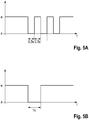
- Fig. 5A shows a diagram illustrating a temporal sequence of a signal for controlling the illumination by the illumination device 32.
- the switched on illumination of the illumination device 32 is denoted by e, a switched off illumination with a. Following the time sequence, it can be seen that the lighting is initially switched on and then switched off or on again three times in 0.5 second intervals. Then the lighting is switched on again continuously.
- the continuous illumination at the beginning and at the end of the time sequence represents the normal operating mode.
- the range recognizable by the pulsed (repeated) switching off and on represents the second signal operating mode.
- the control device 68 operates the lighting device in the normal operating mode if the workpiece sensors of the machine tool do not have a workpiece Detect in the workpiece holder. On the other hand, if the workpiece sensors detect a workpiece in the workpiece holder, the normal operating mode is ended and replaced by a first signal operating mode. If the workpiece sensors continue to detect a faulty seat of the workpiece, the controller 68 sets the second signal operating mode.
- Fig. 5B shows another diagram, which also illustrates a temporal pattern of a signal sequence for controlling the illumination by the illumination device 32.
- the one-time switch-off of the illumination device represents the first signal operating mode.
- the control device 68 sets this first signal operating mode when a workpiece has been correctly picked up in the workpiece holder.
- Fig. 6 11 shows a block diagram of an exemplary embodiment of a monitoring device 62.
- the device 62 includes a workpiece sensor 26, an electronic control device 68, and a lighting device 32.
- the workpiece sensor 26 is configured to detect an environmental signal.
- the workpiece sensor may be a pressure sensor, such as a dynamic pressure sensor, which is configured to receive a pressure signal.
- the workpiece sensor 26 may be a light sensor (light barrier, etc.) configured to receive a light signal.
- Other sensor types are conceivable.
- Various sensors can be combined with each other.
- the workpiece sensor 26 provides the recorded environmental signal 64 as a monitoring signal 70 of the control device 68.
- the control device 68 evaluates the monitoring signal 70 off.
- a corresponding control signal 76 is forwarded to the illumination device 32, which is responsible for controlling the illumination 78 of a working space of a machine tool. In this way, the correct recording of a workpiece, so the correct placement of a workpiece holder can be acknowledged.
- Fig. 7 11 shows a block diagram of a further exemplary embodiment of the device 62.
- this embodiment of the device 62 also has an input unit 80 and a memory unit 82.
- Each of the workpiece sensors 26, 28, 30 is configured to detect a respective state signal 64, 66 and 68 and convert it into a monitoring signal 70, 72, 74, respectively.
- the control device 68 receives these monitoring signals 70, 72, 74.
- the controller 68 is configured to receive an operator input / operator selection 84. This is done either directly via the input unit 18 or via the memory unit 82.
- Suitable input signals are, for example, reference values for the measurement of the workpiece sensors, for example pressure readings for pressure sensors, but also settings concerning the number or design of the operating modes of the lighting device.
- control device 68 All data is then evaluated by the control device 68 and the lighting device 32 or its lighting 78 controlled by means of a control signal 76 to acknowledge the loading / loading of the workpiece holder.
- FIG. 12 is a block diagram illustrating an exemplary embodiment of a method for monitoring a picking status of a workpiece in a machine tool.
- a lighting device is initially operated in a normal operating mode in order to illuminate a working space of the machine tool.
- Another step S12 comprises inserting a workpiece into a workpiece Workpiece holder of a machine tool.
- a further step S14 comprises detecting a picking up status of the workpiece in the workpiece holder with a workpiece sensor. The workpiece sensor then provides in a further step S16 a monitoring signal which describes the recording status of the workpiece.
- step S18 the monitoring signal is evaluated.
- a specific operating mode for the illumination device can be selected in order to enable optical feedback / acknowledgment already in the working space.
- the signal operating mode is selected when a workpiece has been correctly inserted into the workpiece holder.
- step S22 the lighting device is then operated in the signal operating mode to acknowledge the correct recording. Otherwise, the normal operating mode is maintained until the workpiece has been correctly received in the workpiece holder. The process may begin again with step S10.
Abstract
Die vorliegende Offenbarung betrifft eine Vorrichtung zur Überwachung eines Aufnahmestatus eines Werkstücks in einer Werkzeugmaschine, mit einer Beleuchtungseinrichtung zur Beleuchtung des Arbeitsraums in einem Normalbetriebsmodus, zumindest einem Werkstücksensor, der dazu ausgestaltet ist, einen Ist-Zustand des Werkstücks in der Werkstückaufnahme im Arbeitsraum zu erfassen und ein Überwachungssignal bereitzustellen, das den Ist-Zustand des Werkstücks beschreibt, und einer Steuereinrichtung, wobei die Beleuchtungseinrichtung ferner in zumindest einem Signalbetriebsmodus betreibbar ist, und wobei die Steuereinrichtung dazu ausgestaltet ist, eine Zuordnung des Ist-Zustands zu zumindest einem ersten Aufnahmestatus und einem zweiten Aufnahmestatus in Abhängigkeit von dem Überwachungssignal vorzunehmen, und die Beleuchtungseinrichtung in Abhängigkeit von der Zuordnung selektiv in dem Signalbetriebsmodus zu betreiben, um im Arbeitsraum eine visuelle Information zur Veranschaulichung des Aufnahmestatus des Werkstücks bereitzustellen. Ferner betrifft die Offenbarung eine Werkzeugmaschine mit einer solchen Überwachungsvorrichtung, ein Verfahren zur Überwachung eines Aufnahmestatus und ein entsprechendes Maschinensteuerungsprogramm.The present disclosure relates to a device for monitoring a recording status of a workpiece in a machine tool, with an illumination device for illuminating the work space in a normal operating mode, at least one workpiece sensor which is designed to detect an actual state of the workpiece in the workpiece fixture in the work space and to provide a monitoring signal that describes the actual state of the workpiece, and a control device, wherein the lighting device can also be operated in at least one signal operating mode, and wherein the control device is configured to assign the actual state to at least a first recording status and a second one Record status depending on the monitoring signal, and to operate the lighting device depending on the assignment selectively in the signal operating mode to visualize visual information in the workspace g of the recording status of the workpiece. Furthermore, the disclosure relates to a machine tool with such a monitoring device, a method for monitoring a recording status and a corresponding machine control program.
Description
Die vorliegende Offenbarung bezieht sich auf eine Vorrichtung zur Überwachung eines Aufnahmestatus eines Werkstücks in einer Werkzeugmaschine oder einer definierten Umgebung einer Werkzeugmaschine. Ferner bezieht sich die vorliegende Offenbarung auf eine Werkzeugmaschine mit einer solchen Vorrichtung, ein Verfahren zur Überwachung eines Aufnahmestatus und ein entsprechendes Maschinensteuerungsprogramm.The present disclosure relates to an apparatus for monitoring a picking status of a workpiece in a machine tool or a defined environment of a machine tool. Further, the present disclosure relates to a machine tool having such a device, a method for monitoring a pickup status and a corresponding machine control program.
Vorrichtungen der vorgenannten Art sind allgemein bekannt. Sie werden häufig in Werkzeugmaschinen zur Bearbeitung von Metallen bzw. fester Werkstoffe eingesetzt, insbesondere in CNC-Werkzeugmaschinen. Mit Hilfe derartiger Vorrichtungen kann unterschieden werden, ob sich überhaupt ein Werkstück in der Werkzeugmaschine oder einer zugeordneten Umgebung befindet oder nicht. Ferner kann sichergestellt werden, dass sich ein Werkstück in einer für dessen Bearbeitung erforderlichen Position befindet.Devices of the aforementioned type are well known. They are often used in machine tools for machining metals or solid materials, especially in CNC machine tools. With the help of such devices can be distinguished whether there is a workpiece in the machine tool or an associated environment or not. Furthermore, it can be ensured be that a workpiece is in a required position for its processing.
Die Überprüfung des Aufnahmestatus erfolgt dabei über eine Sensorik. Bei den eingesetzten Sensoren handelt es sich in der Regel um Druckluft- bzw. Staudrucksensoren, welche das Werkstück (bzw. den für das Werkstück vorgesehenen Raum) mit einem Luftstrahl aus einer Sensordüse abtasten. Durch eine anschließende Auswertung des entstehenden Rückstaudruckes kann unter anderem eine Aussage über die Anwesenheit und/oder Position eines Werkstücks in einer Werkstückaufnahme getroffen werden. Wenn das Werkstück wie vorgesehen aufgenommen ist, ergeben sich entsprechende Messwerte für den gemessenen Staudruck. Wenn das Werkstück hingegen falsch positioniert ist, ergeben sich abweichende Messerwerte, die den fehlerhaften Sitz anzeigen.The check of the recording status is done via a sensor. The sensors used are usually compressed air or dynamic pressure sensors which scan the workpiece (or the space provided for the workpiece) with an air jet from a sensor nozzle. By a subsequent evaluation of the resulting back pressure can be taken, among other things, a statement about the presence and / or position of a workpiece in a workpiece holder. If the workpiece is picked up as intended, corresponding measured values for the measured back pressure result. On the other hand, if the workpiece is positioned incorrectly, deviating knife values will be displayed indicating the incorrect fit.
Vor allem bei der Fertigung von Einzelexemplaren oder kleinen Serien erfolgt die Bestückung der Werkzeugmaschinen manuell. Insofern ist der Bediener bzw. Werker selbst dafür verantwortlich, dass das Werkstück wie vorgesehen in die Werkzeugmaschine aufgenommen wird. Eine entsprechende unterstützende Zustandsüberwachung des Werkstücks ist daher hilfreich, wenn eine präzise Fertigung und ein fehlerarmer Betrieb gewährleistet sein sollen.Especially in the production of single copies or small series, the machine tools are loaded manually. In this respect, the operator or the worker is responsible for ensuring that the workpiece is received in the machine tool as intended. A corresponding supportive condition monitoring of the workpiece is therefore helpful if precise production and low-error operation are to be ensured.
Aus der
Aus der
Eine Rückmeldung über den Aufnahmestatus des Werkstücks, also zum Beispiel über dessen Position, erfolgt für den Maschinenbediener üblicherweise an einem Bedien-Panel an der Außenhülle einer Werkzeugmaschine. Eine derartige Werkzeugmaschine und Vorrichtung zur Werkstücküberwachung sind beispielsweise aus der
Vor diesem Hintergrund liegt der vorliegenden Offenbarung die Aufgabe zugrunde, Überwachungsvorrichtungen und damit versehene Werkzeugmaschinen weiterzubilden, um die Bestückung mit Werkstücken zu vereinfachen. Dies soll mit einem möglichst geringen Mehraufwand erzielbar sein. Allgemein soll die Überwachungsvorrichtung dazu beitragen, Werkstückwechselzeiten zu minimieren. Die Bedienerergonomie soll möglichst verbessert werden. Ferner sollen die Qualität und Genauigkeit der Bearbeitung sowie die Zuverlässigkeit der Werkzeugmaschine insgesamt erhöht werden.Against this background, the present disclosure has the object, training monitoring devices and machine tools provided therewith in order to simplify the assembly of workpieces. This should be achievable with the least possible additional effort. In general, the monitoring device should help to minimize workpiece change times. The operator ergonomics should be improved as much as possible. Furthermore, the quality and accuracy of the processing and the reliability of the machine tool to be increased overall.
Die Vorrichtung betreffend wird diese Aufgabe gelöst durch eine Vorrichtung zur Überwachung eines Aufnahmestatus eines Werkstücks in einer Werkstückaufnahme in einem Arbeitsraum oder einer definierten Umgebung einer Werkzeugmaschine, wobei die Vorrichtung Folgendes aufweist:
- eine Beleuchtungseinrichtung zur Beleuchtung des Arbeitsraums in einem Normalbetriebsmodus,
- zumindest einen Werkstücksensor, der dazu ausgestaltet ist, einen Ist-Zustand des Werkstücks in der Werkstückaufnahme im Arbeitsraum zu erfassen und ein Überwachungssignal bereitzustellen, das den Ist-Zustand des Werkstücks beschreibt, und
- eine Steuereinrichtung,
wobei die Steuereinrichtung dazu ausgestaltet ist, auf Basis des Überwachungssignals zu bestimmen, ob sich das Werkstück in einem ersten Aufnahmestatus oder einem zweiten Aufnahmestatus befindet, und die Beleuchtungseinrichtung auf dieser Basis selektiv in dem Signalbetriebsmodus zu betreiben, um im Arbeitsraum eine visuelle Information zur Veranschaulichung des Aufnahmestatus des Werkstücks bereitzustellen.With regard to the device, this object is achieved by a device for monitoring a picking up status of a workpiece in a workpiece holder in a working space or a defined environment of a machine tool, the device comprising:
- a lighting device for illuminating the working space in a normal operating mode,
- at least one workpiece sensor, which is configured to detect an actual state of the workpiece in the workpiece holder in the working space and to provide a monitoring signal, which describes the actual state of the workpiece, and
- a control device,
wherein the controller is configured to determine whether the workpiece is in a first take-up state or a second take-up state based on the monitor signal, and selectively operate the lighting device in the signal operating mode to provide visual information in the work space to illustrate To provide recording status of the workpiece.
Die Aufgabe der Erfindung wird auf diese Weise vollständig gelöst.The object of the invention is completely solved in this way.
Erfindungsgemäß greift die Vorrichtung zur Signalisierung/Quittierung des Aufnahmestatus eines Werkstücks in der Werkzeugmaschine nämlich auf die ohnehin bereits verbaute Beleuchtungseinrichtung des Arbeitsraums zurück. Auf eine Signalisierung an einem Bedien-Panel an der Außenseite der Werkzeugmaschine kann im Idealfall verzichtet werden. Um eine Rückmeldung über den Aufnahmestatus zu erhalten, muss sich der Bediener somit nicht mehr aus dem Arbeitsraum herausbewegen/zurücklehnen. Stattdessen erhält der Bediener bzw. Werker noch im Arbeitsraum der Werkzeugmaschine Informationen über den Aufnahmestatus und kann unmittelbar reagieren und den Sitz des Werkstücks gegebenenfalls korrigieren. Die Werkstückwechselzeit kann reduziert werden. Der Bearbeiter ist vor ergonomisch ungünstigen Bewegungen seines Körpers geschützt.According to the invention, the device for signaling / acknowledging the picking up status of a workpiece in the machine tool in fact falls back on the lighting device of the working space, which is already installed anyway. On a signaling on a control panel on the outside of the machine tool can be dispensed with in the ideal case. In order to receive feedback on the recording status, the operator no longer has to move out of the working space / sit back. Instead, the operator or worker still receives information about the recording status in the working space of the machine tool and can react immediately and if necessary correct the seat of the workpiece. The workpiece change time can be reduced. The operator is protected from ergonomically unfavorable movements of his body.
Mit anderen Worten kann die Überwachungsvorrichtung beispielsweise den korrekten Sitz des Werkstücks direkt im Arbeitsraum über die dort ohnehin vorhandene Beleuchtung quittieren. Die Quittierung erfolgt visuell über Lichtsignale bzw. Leuchtsignale. Die Quittierung erfolgt zumindest in beispielhaften Ausführungsformen über die Beleuchtung des Arbeitsraums, die über die Steuereinrichtung selektiv aktiviert wird. Die Beleuchtung leuchtet im Normalbetriebsmodus den Arbeitsraum aus, um für gute Sichtverhältnisse zu sorgen. In dem zumindest einen Signalbetriebsmodus wird die Beleuchtung zur Informationsübertragung genutzt, um dem Bediener/Werker noch im Arbeitsraum zu signalisieren, ob das Werkstück korrekt platziert wurde oder nicht.In other words, the monitoring device can acknowledge, for example, the correct seat of the workpiece directly in the working area via the illumination which is present there anyway. The acknowledgment takes place visually via light signals or light signals. The acknowledgment takes place, at least in exemplary embodiments, via the illumination of the working space, which is selectively activated via the control device. The lighting illuminates the working area in normal operating mode to provide good visibility. In the at least one signal operating mode, the illumination is used for information transmission in order to signal the operator / worker still in the work space whether the workpiece has been correctly placed or not.
Ferner bietet die Vorrichtung gemäß dem obigen Aspekt den Vorteil, dass keine neuen Komponenten (struktureller Art) verbaut werden müssen. Die Steuereinrichtung ist dazu ausgestaltet ist, die im Arbeitsraum vorhandene Beleuchtungseinrichtung anzusteuern und über diese Beleuchtungseinrichtung dem Bediener bzw. Werker Rückmeldung über den Aufnahmestatus des Werkstücks zu geben. Eine Signalausgabe am Bedien-Panel ist damit nicht mehr unbedingt notwendig, kann aber zusätzlich erfolgen. Gegebenenfalls kann sogar auf bestehende Maschinenkomponenten, wie etwa einzelne Signalleuchten, am Bedien-Panel verzichtet werden. Die Vorrichtung eignet sich zur Nachrüstung bestehender Systeme. Diese können in einfacher Weise nachgerüstet werden.Furthermore, the device according to the above aspect offers the advantage that no new components (structural type) must be installed. The control device is designed to control the lighting device present in the working space and to give the operator or worker feedback about the picking status of the work piece via this lighting device. A signal output on the control panel is therefore no longer absolutely necessary, but can be done additionally. If necessary, even existing machine components, such as individual signal lights, can be dispensed with on the control panel. The device is suitable for retrofitting existing systems. These can be retrofitted in a simple manner.
Der Ist-Zustand ist ein gegenwärtig erfasster (realer) Zustand. Der Soll-Zustand ist ein Zielzustand bzw. ein gewünschter Zustand. Die Zustände können sich hinsichtlich der korrekten Aufnahme des Werkstücks in der Werkstückaufnahme ergeben. Sodann kann die Vorrichtung dazu genutzt werden, zu ermitteln, ob das Werkstück richtig oder womöglich falsch aufgenommen ist. Die spiegelt sich in den Aufnahmestatus wieder.The actual state is a currently detected (real) state. The target state is a target state or a desired state. The conditions may arise with regard to the correct picking up of the workpiece in the workpiece holder. Then, the device can be used to determine whether the workpiece is correctly or possibly incorrectly recorded. This is reflected in the recording status again.
Bei der Beleuchtungseinrichtung handelt es sich, zumindest in beispielhaften Ausführungsformen, um zumindest eine Lichtquelle, insbesondere eine Lichtquelle zur Erzeugung polychromatischen Lichtes, insbesondere um eine zumindest Weißlichtquelle. Die Beleuchtungseinrichtung dient zum Beleuchten, insbesondere zum Ausleuchten des Arbeitsraums für den Bediener. Auf diese Weise verbessert sich die Beobachtbarkeit und Überwachbarkeit. Lichtquellen umfassen beispielsweise Glühlampen, Halogenlampen, LED-Lampen, Leuchtstofflampen und Natriumdampf-Hochdrucklampen. Weißlicht umfasst beispielsweise die Emission breitbandigen Lichtes mit geeigneter Farbtemperatur, etwa Tageslichtweiß oder Neutralweiß. Allgemein wird eine für die Anwendung passende Farbtemperatur gewählt.The illumination device is, at least in exemplary embodiments, at least one light source, in particular a light source for generating polychromatic light, in particular an at least white light source. The illumination device is used for illuminating, in particular for illuminating the working space for the operator. This improves observability and monitorability. Light sources include, for example, incandescent lamps, halogen lamps, LED lamps, fluorescent lamps and high-pressure sodium vapor lamps. White light includes, for example, the emission of broadband light with a suitable color temperature, such as daylight white or neutral white. In general, a color temperature suitable for the application is selected.
Die vorstehende Ausgestaltung der Überwachungseinrichtung eignet sich insbesondere für die Überwachung von Werkstücken, bzw. von deren Aufnahmezustand im Arbeitsraum der Werkzeugmaschine.The above embodiment of the monitoring device is particularly suitable for the monitoring of workpieces, or of their receiving state in the working space of the machine tool.
Ferner ermöglicht die Vorrichtung einen unter ergonomischen Gesichtspunkten verbesserten Bestückungsvorgang. Zur Überprüfung der Bestückung muss sich der Werker nicht mehr umständlich aus dem Arbeitsraum zurücklehnen, um ein Quittierungssignal über ein Display oder sonstige Anzeige an der Außenseite der Werkzeugmaschine zu erfassen. Vielmehr kann der Werker nun den Aufnahmestatus des Werkstücks direkt während der Bestückung bzw. seines Aufenthalts im Arbeitsraum bzw. Bedienraum der Werkzeugmaschine überprüfen.Furthermore, the device allows an ergonomically improved assembly process. To check the assembly, the worker no longer has to lean awkwardly out of the working space to detect an acknowledgment signal via a display or other display on the outside of the machine tool. Rather, the worker can now check the recording status of the workpiece directly during the assembly or his residence in the working space or operating space of the machine tool.
Ferner können die Signale unter Verwendung einer Speicher- und Auswerteeinheit beispielsweise zur Bereitstellung von Zustandshistorien genutzt werden.Furthermore, the signals can be used, for example, to provide state histories using a memory and evaluation unit.
Bei der definierten Umgebung handelt es sich beispielsweise um einen Pufferspeicher, eine temporär außerhalb des Arbeitsraumes angeordnete auswechselbare Aufnahmevorrichtung, und/oder eine Aufnahme für das Werkstück ein einer Handhabungseinrichtung, die dann den Arbeitsraum bestückt.The defined environment is, for example, a buffer store, an interchangeable receiving device which is temporarily arranged outside the working space, and / or a receptacle for the workpiece, a handling device which then loads the working space.
In einer beispielhaften Ausgestaltung ordnet die Steuereinrichtung den Ist-Zustand dem ersten Aufnahmestatus zu, wenn der Ist-Zustand mit einem Soll-Zustand übereinstimmt, und wobei die Steuereinrichtung den Ist-Zustand dem zweiten Aufnahmestatus zuordnet, wenn der Ist-Zustand nicht mit dem Soll-Zustand übereinstimmt. Als Soll-Zustand ist beispielsweise die korrekte Aufnahme eines Werkstücks in ein Spannnest definiert. Wenn das Werkstück den richtigen Sitz im Spannnest hat, stimmen Ist-Zustand und Soll-Zustand überein. Die Steuereinrichtung ordnet den Ist-Zustand dann dem ersten Aufnahmestatus zu. Ist der Sitz hingegen nicht korrekt, weil zum Beispiel eine Spannbacke das Werkstück nicht richtig fasst, findet eine Zuordnung zum zweiten Aufnahmestatus statt. Dies kann auch bedeuten, dass der zweite Aufnahmestatus ausgewählt wird, wenn sich überhaupt kein Werkstück in der Werkstückaufnahme befindet.In an exemplary embodiment, the control device assigns the actual state to the first intake state when the actual state coincides with a desired state, and wherein the control device assigns the actual state to the second intake state if the actual state does not match the target State matches. As a desired state, for example, the correct recording of a workpiece is defined in a clamping nest. If the workpiece has the correct seat in the clamping nest, the actual state and target state match. The controller then assigns the current state to the first recording state. If, on the other hand, the seat is not correct because, for example, a clamping jaw does not grasp the workpiece correctly, an assignment to the second recording status takes place. This can also mean that the second recording status is selected if there is no workpiece at all in the workpiece holder.
In einer weiteren beispielhaften Ausgestaltung betreibt die Steuereinrichtung die Beleuchtungseinrichtung in dem Signalbetriebsmodus, wenn der Ist-Zustand dem ersten Aufnahmestatus zugeordnet ist bzw. wenn durch das Überwachungssignal angezeigt wird, dass sich das Werkstück im ersten Aufnahmestatus befindet. Der Modus der Beleuchtungseinrichtung wird vom Normalbetriebsmodus also erst dann in den Signalbetriebsmodus umgestellt, wenn der Ist-Zustand des Werkstücks mit dem Soll-Zustand übereinstimmt. Beispielsweise wird der Signalbetriebsmodus erst dann aktiviert, wenn das Werkstück in Bezug auf alle dafür vorgesehenen Befestigungselemente korrekt platziert wurde.In a further exemplary embodiment, the control device operates the illumination device in the signal operating mode if the actual state is associated with the first recording state or if the monitoring signal indicates that the workpiece is in the first recording state. The mode of Lighting device is thus converted from the normal operating mode only in the signal operating mode when the actual state of the workpiece coincides with the target state. For example, the signal operating mode is activated only when the workpiece has been correctly placed with respect to all the fasteners provided.
In einer vorteilhaften Ausgestaltung ist die Beleuchtungseinrichtung in den Arbeitsraum integriert. Vorzugsweise sind von der Beleuchtungseinrichtung ausgegebene Signale im Arbeitsraum sichtbar. Üblicherweise ist der Arbeitsraum einer Werkzeugmaschine ohnehin mit einer Beleuchtungseinrichtung ausgestattet, die dem Werker das Überwachen der Werkstückbearbeitung erleichtert. Grundsätzlich ist zwar auch eine Beleuchtung des Arbeitsraums durch eine Beleuchtungseinrichtung außerhalb des Arbeitsraums denkbar, hier ist aber oftmals eine Behinderung des Werkers durch Beschattungseffekte gegeben.In an advantageous embodiment, the lighting device is integrated into the working space. Preferably, signals emitted by the illumination device are visible in the working space. Usually, the working space of a machine tool is already equipped with a lighting device that makes it easier for the worker to monitor the workpiece machining. In principle, although a lighting of the work space by a lighting device outside the work space is conceivable, but here is often a disability of the worker given by shading effects.
In einer weiteren vorteilhaften Ausgestaltung ist die Beleuchtungseinrichtung in einem ersten Signalbetriebsmodus und in einem zweiten Signalbetriebsmodus betreibbar, wobei die Steuereinrichtung die Beleuchtungseinrichtung in dem ersten Signalbetriebsmodus betreibt, wenn der Ist-Zustand dem ersten Aufnahmestatus zugeordnet ist, und wobei die Steuereinrichtung die Beleuchtungseinrichtung in dem zweiten Signalbetriebsmodus betreibt, wenn der Ist-Zustand dem zweiten Aufnahmestatus zugeordnet ist. Das bedeutet, dass der Modus der Beleuchtungseinrichtung vom zweiten auf den ersten Signalbetriebsmodus umgestellt wird, sobald der Ist-Zustand des Werkstücks mit dem Soll-Zustand übereinstimmt. Es ist beispielsweise vorgesehen, dass die Beleuchtungseinrichtung der Vorrichtung im Normalbetriebsmodus betrieben wird, so lange sich überhaupt kein Werkstück im Arbeitsraum der Werkzeugmaschine befindet. Beispielhafte Ausführungsformen sehen vor, dass die Beleuchtungseinrichtung im zweiten Signalbetriebsmodus betrieben wird, wenn der Werkstücksensor ein Werkstück erfasst, das Werkstück sich aber noch nicht im Soll-Zustand befindet. Wenn der Bediener das Werkstück dann in den Soll-Zustand gebracht hat, wird der Modus der Beleuchtungseinrichtung ein weiteres Mal umgestellt, und zwar in den ersten Signalbetriebsmodus, um dies zu quittieren.In a further advantageous refinement, the illumination device is operable in a first signal operating mode and in a second signal operating mode, wherein the control device operates the illumination device in the first signal operating mode when the actual state is associated with the first recording state, and wherein the control device controls the illumination device in the second Signal operating mode operates when the current state is associated with the second recording status. This means that the mode of the illumination device is changed over from the second to the first signal operating mode as soon as the actual state of the workpiece coincides with the desired state. For example, it is provided that the illumination device of the device is operated in the normal operating mode as long as there is no workpiece at all in the working space of the machine tool. Exemplary embodiments provide that the illumination device is operated in the second signal operating mode when the workpiece sensor detects a workpiece, but the workpiece is not yet in the desired state. If the operator has then brought the workpiece to the desired state, the mode of the illumination device is changed over again, in the first signal operating mode to acknowledge this.
Gemäß einer beispielhaften Ausgestaltung ist die Beleuchtungseinrichtung zur Ausgabe von im Zeitablauf binären oder dreistufigen Signalen betreibbar. Es ist beispielsweise vorstellbar, die Beleuchtungseinrichtung in drei zeitlichen Stufen zu betreiben. Unter den drei Stufen des Betriebs der Beleuchtungseinrichtung ist etwa zu verstehen, dass die Beleuchtungseinrichtung für eine erste Zeitdauer und eine zweite Zeitdauer aktiviert werden kann, sowie für eine dritte Zeitdauer deaktiviert werden kann. Beispielsweise ist die erste Zeitdauer länger als die zweite Zeitdauer, und beispielsweise ist die zweite Zeitdauer länger als die dritte Zeitdauer. Die Beleuchtung der Beleuchtungseinrichtung kann also beispielsweise im Signalbetriebsmodus zunächst für fünf Sekunden aktiviert werden, dann für eine Sekunde deaktiviert werden, wieder für 2,5 Sekunden aktiviert werden und dann wieder für eine Sekunde deaktiviert werden. Dies dient jedoch lediglich zur Veranschaulichung und ist nicht einschränkend zu verstehen. Der dreistufige Betrieb entspricht insofern einem Lichtmorse-Modus. Andere Signalfolgen sind denkbar.According to an exemplary embodiment, the illumination device is operable to output binary or three-stage signals over time. For example, it is conceivable to operate the illumination device in three temporal stages. By the three stages of operation of the illumination device, it is to be understood that the illumination device may be activated for a first time duration and a second time duration, as well as being deactivated for a third time duration. For example, the first time period is longer than the second time duration, and for example, the second time duration is longer than the third time duration. The illumination of the illumination device can thus be activated, for example, in the signal operating mode initially for five seconds, then deactivated for one second, activated again for 2.5 seconds and then deactivated again for one second. However, this is for illustrative purposes only and is not meant to be limiting. The three-stage operation corresponds to a Lichtmorse mode. Other signal sequences are conceivable.
In einer weiteren beispielhaften Ausgestaltung umfasst der Signalbetriebsmodus der Vorrichtung ein selektives Deaktivieren und/oder Aktivieren der Beleuchtungseinrichtung. Es ist vorstellbar, dass die Beleuchtungseinrichtung im Normalbetriebsmodus durchgehend aktiviert ist und beim Wechsel in den Signalbetriebsmodus (zumindest kurzzeitig) deaktiviert wird. Die Dauer der Beleuchtungsdeaktivierung kann im Prinzip beliebig sein. Allerdings sind ein lediglich kurzes Ausschalten und eine baldige Rückkehr in den Normalbetriebsmodus von Vorteil, da der Bediener bzw. Werker dann auch während der Werkstückbearbeitung einen nahezu vollständig und dauerhaft beleuchteten Arbeitsraum vorfindet. Um dem Bediener bzw. Werker deutlich zu machen, dass der Ist-Zustand des Werkstücks mit dem Soll-Zustand übereinstimmt, kann der Signalbetriebsmodus auch ein mehrmaliges Deaktivieren bzw. Aktivieren der Beleuchtungseinrichtung umfassen (pulsierende Beleuchtung). So kann die Beleuchtung beispielsweise für eine vordefinierte Zeit blinken, sobald der vorgesehene Aufnahmestatus des Werkstücks erreicht wurde.In a further exemplary embodiment, the signal operating mode of the device comprises a selective deactivation and / or activation of the illumination device. It is conceivable that the lighting device is activated continuously in the normal operating mode and is deactivated (at least for a short time) when changing to the signal operating mode. The duration of the illumination deactivation can in principle be arbitrary. However, only a short switch off and an early return to the normal mode of operation are advantageous, since the operator or worker then finds a virtually completely and permanently illuminated work space during workpiece machining. In order to make it clear to the operator or the worker that the actual state of the workpiece coincides with the desired state, the signal operating mode can also include a repeated deactivation or activation of the illumination device (pulsating illumination). For example, the light may flash for a predefined time as soon as the intended recording status of the work piece has been reached.
In einer weiteren Ausgestaltung der Vorrichtung umfasst der Signalbetriebsmodus eine Änderung einer Beleuchtungsstärke und/oder einer Beleuchtungsfarbe. Beispielsweise veranlasst die Steuereinrichtung einen kurzen Wechsel der Beleuchtungsfarbe (zum Beispiel von Weiß auf Grün, oder von Rot auf Grün), wenn der gewünschte Aufnahmestatus erreicht ist und die Beleuchtungseinrichtung im Signalbetriebsmodus betrieben wird. Die Beleuchtungsstärke kann analog zur Aktivierung/Deaktivierung variiert werden (einmaliger Impuls oder Pulsieren).In a further embodiment of the device, the signal operating mode comprises a change in illuminance and / or illumination color. For example, the control device causes a brief change of the illumination color (For example, from white to green, or from red to green), when the desired recording status is reached and the lighting device is operated in the signal operating mode. The illuminance can be varied analogously to the activation / deactivation (single impulse or pulsation).
Gemäß einer weiteren beispielhaften Ausgestaltung umfasst der Ist-Zustand eine Zustandsgröße, die aus der Gruppe ausgewählt ist, die aus Folgendem besteht: Anwesenheit, Abwesenheit, Position, Orientierung, ein Spannzustand des Werkstücks, sowie beliebige Kombinationen daraus. Selbiges gilt für den Soll-Zustand. Insbesondere ist denkbar, dass die Steuereinrichtung aus dem von dem mindestens einen Werkstücksensor bereitgestellten Überwachungssignal, welches den Ist-Zustand des Werkstücks beschreibt, ableitet, ob das Werkstück in korrekter Lage und Ausrichtung in der Werkstückaufnahme aufgenommen wurde. Ferner kann die Steuereinrichtung dazu ausgestaltet sein, anhand des Überwachungssignals zu erkennen, ob ein Werkstück fest genug eingespannt ist.According to a further exemplary embodiment, the actual state comprises a state variable selected from the group consisting of: presence, absence, position, orientation, a clamping state of the workpiece, and any combinations thereof. The same applies to the target state. In particular, it is conceivable that the control device deduces from the monitoring signal provided by the at least one workpiece sensor, which describes the actual state of the workpiece, whether the workpiece was received in the correct position and orientation in the workpiece holder. Furthermore, the control device can be designed to detect on the basis of the monitoring signal whether a workpiece is clamped firmly enough.
Gemäß einer weiteren beispielhaften Ausgestaltung der Vorrichtung ist der zumindest eine Werkstücksensor aus der Gruppe ausgewählt, die aus Folgendem besteht: mechanische Sensoren, optische Sensoren, induktive Sensoren, elektrische Sensoren, Wegsensoren, Drucksensoren, Kraftsensoren ist, sowie Kombinationen daraus. Durch Staudrucksensoren kann in einfacher Weise überprüft werden, ob ein Werkstück richtig positioniert bzw. eingespannt ist. Dadurch können zum Beispiel auch Fehlfunktionen einer Werkstückspanneinrichtung während des Betriebs erfasst und von der Steuerung berücksichtigt werden.According to another exemplary embodiment of the device, the at least one workpiece sensor is selected from the group consisting of: mechanical sensors, optical sensors, inductive sensors, electrical sensors, displacement sensors, pressure sensors, force sensors, and combinations thereof. By dynamic pressure sensors can be easily checked whether a workpiece is correctly positioned or clamped. As a result, for example, malfunctions of a workpiece clamping device can be detected during operation and taken into account by the controller.
Gemäß einer weiteren beispielhaften Ausgestaltung weist die Vorrichtung ferner eine Eingabeeinheit auf, die dazu ausgestaltet ist, Bedienereingaben/Selektionen aufzunehmen, die für die Steuereinrichtung zur Steuerung der Beleuchtungseinrichtung bestimmt sind. Unter Bedienereingaben ist etwa eine konkrete Auswahl betreffend ein oder mehrere zeitliche, räumliche und/oder farbige Signale oder Signalfolgen für die Quittierung oder allgemein die Rückmeldung zum Aufnahmestatus zu verstehen. Ferner können die Nutzerinformationen auch Informationen darüber umfassen, ob der Nutzer, d.h. der Werker bzw. Bediener, zusätzlich zum ersten Signalbetriebsmodus einen zweiten Signalbetriebsmodus (Fehleranzeige) wünscht. Es versteht sich, dass die Eingabeeinheit ein Bestandteil der Vorrichtung bilden kann, aber auch als eine von der Vorrichtung separate Einheit betrieben werden kann.According to a further exemplary embodiment, the device further has an input unit that is configured to receive operator inputs / selections that are intended for the control device for controlling the illumination device. Operator input means, for example, a concrete selection relating to one or more temporal, spatial and / or colored signals or signal sequences for the acknowledgment or in general the response to the recording status. Furthermore, the user information may also include information as to whether the user, ie the operator, is in addition to the first signal operating mode wants a second signal operating mode (error indication). It is understood that the input unit can form part of the device, but can also be operated as a unit separate from the device.
Beispielhaft ist die Steuereinrichtung dazu ausgestaltet, eine Beleuchtungseinrichtung in einem Beladebereich einer Werkzeugmaschine zu steuern. Dies gilt insbesondere für solche Werkzeugmaschinen, bei denen der Arbeitsraum den eigentlichen Arbeitsbereich, in dem die Bearbeitung stattfindet, sowie einen Beladebereich umfasst, in dem ein Werkstückwechsel erfolgt. Zu diesem Zweck ist es vorstellbar, die Werkzeugmaschine mit zumindest zwei Werkstückaufnahmen zu versehen, die zwischen einer Beladeposition/Bestückungsposition und einer Bearbeitungsposition verlagert werden können. Insbesondere kann die Steuereinrichtung dazu ausgestaltet sein, die Beleuchtungseinrichtung im Beladebereich in Abhängigkeit von dem durch den mindestens einen Werkstücksensor bereitgestellten Überwachungssignal selektiv im Signalbetriebsmodus zu betreiben, um auch im Beladebereich eine visuelle Information zur Veranschaulichung des Aufnahmestatus des Werkstücks bereitzustellen.By way of example, the control device is designed to control a lighting device in a loading area of a machine tool. This applies in particular to those machine tools in which the working space comprises the actual working area in which the machining takes place and a loading area in which a workpiece change takes place. For this purpose, it is conceivable to provide the machine tool with at least two workpiece holders which can be displaced between a loading position / loading position and a processing position. In particular, the control device can be configured to selectively operate the illumination device in the loading area as a function of the monitoring signal provided by the at least one workpiece sensor in the signal operating mode in order to provide visual information in the loading area to illustrate the picking status of the workpiece.
Bei der Beleuchtungseinrichtung im Arbeitsraum oder auch Beladebereich handelt es sich vorzugsweise um eine oder mehrere Leuchtdioden (LEDs). Zum einen bietet die vergleichsweise lange Lebensdauer von LEDs eine wartungsarme Beleuchtung. Zum anderen ist die Erwärmung von LEDs im Betrieb minderwichtig. Andere technische Lösungen zur Lichtsignalisierung sind ebenfalls einsetzbar.The lighting device in the working space or loading area is preferably one or more light-emitting diodes (LEDs). On the one hand, the comparatively long lifetime of LEDs offers low-maintenance lighting. On the other hand, the heating of LEDs during operation is of minor importance. Other technical solutions for light signaling can also be used.
Die obige Aufgabe wird ferner durch eine Werkzeugmaschine gelöst, mit
- einem Gestell,
- einem Arbeitsraum mit einer Werkstückaufnahme zur Aufnahme eines Werkstücks, und
- einer Überwachungsvorrichtung gemäß zumindest einer hierin beschriebenen Ausführungsform, die zur Überwachung des Aufnahmestatus des Werkstücks in der Aufnahme ausgebildet ist.
- a frame,
- a work space with a workpiece holder for receiving a workpiece, and
- a monitoring device according to at least one embodiment described herein, which is designed to monitor the picking up status of the workpiece in the receptacle.
Auch auf diese Weise wird die Aufgabe der Erfindung gelöst.Also in this way the object of the invention is achieved.
Die Werkzeugmaschine ist beispielsweise als Drehmaschine, Fräsmaschine, Lasermaschine (Laserbearbeitungsmaschine), und/oder als kombinierte Maschine zur Dreh-, Fräs- und/oder Laserbearbeitung ausgeführt. Insbesondere handelt sich um eine sogenannte Mehrachsmaschine mit einer Mehrzahl gesteuerter Achsen. Insbesondere umfasst die Werkzeugmaschine eine Einhausung mit einer verschließbaren Öffnung, die einen Zugang in den Arbeitsraum erlaubt. Grundsätzlich kann es sich aber auch um andere Arten und Ausgestaltungen von Werkzeugmaschinen handeln. Das Gestell kann auch als Maschinenbett bezeichnet werden oder ausgeführt sein.The machine tool is designed for example as a lathe, milling machine, laser machine (laser processing machine), and / or as a combined machine for turning, milling and / or laser machining. In particular, it is a so-called multi-axis machine with a plurality of controlled axes. In particular, the machine tool comprises an enclosure with a closable opening which allows access to the working space. In principle, however, it can also be other types and configurations of machine tools. The frame can also be referred to as a machine bed or executed.
Das Verfahren betreffend wird die obige Aufgabe gelöst durch ein Verfahren zur Überwachung eines Aufnahmestatus eines Werkstücks in einer Werkstückaufnahme in einem Arbeitsraum oder einer definierten Umgebung einer Werkzeugmaschine. Dabei umfasst das Verfahren die folgenden Schritte:
- Betreiben einer Beleuchtungseinrichtung in einem Normalbetriebsmodus zur Beleuchtung des Arbeitsraums,
- Aufnehmen eines Werkstücks in der Werkstückaufnahme im Arbeitsraum,
- Erfassen des Ist-Zustands des Werkstücks in der Werkstückaufnahme im Arbeitsraum,
- Bereitstellen eines Überwachungssignals, das den Ist-Zustand des Werkstücks beschreibt,
- Bestimmen, auf Basis des Überwachungssignals, ob sich das Werkstück in einem ersten Aufnahmestatus oder einem zweiten Aufnahmestatus befindet, und
- auf dieser Basis, selektives Betreiben der Beleuchtungseinrichtung in einem Signalbetriebsmodus, um im Arbeitsraum eine visuelle Information zur Veranschaulichung des Aufnahmestatus des Werkstücks bereitzustellen.
- Operating a lighting device in a normal operating mode for illuminating the working space,
- Picking up a workpiece in the workpiece holder in the working space,
- Detecting the actual state of the workpiece in the workpiece holder in the working space,
- Providing a monitoring signal which describes the actual state of the workpiece,
- Determining, based on the monitoring signal, whether the workpiece is in a first recording state or a second recording state, and
- on this basis, selectively operating the lighting device in a signal operating mode to provide visual information in the workspace to illustrate the picking status of the workpiece.
Auch auf diese Weise wird die der Erfindung zugrunde liegende Aufgabe gelöst.Also in this way the object underlying the invention is achieved.
Die Aufgabe wird ferner gelöst durch ein Maschinensteuerungsprogramm, das Programmcode aufweist, der dazu ausgestaltet ist, eine Steuereinrichtung einer Werkzeugmaschine zu veranlassen, die Schritte des Verfahrens gemäß einem Ausführungsbeispiel der vorliegenden Offenbarung auszuführen, wenn das Maschinensteuerungsprogramm auf der Steuereinrichtung ausgeführt wird.The object is further achieved by a machine control program having program code configured to cause a controller of a machine tool to execute the steps of the method according to an embodiment of the present disclosure when the machine control program is executed on the controller.
Es versteht sich, dass die vorstehend genannten und die nachfolgend noch zu erläuternden Merkmale der Erfindung nicht nur in der jeweils angegebenen Kombination, sondern auch in anderen Kombinationen oder in Alleinstellung verwendbar sind, ohne den Rahmen der Erfindung zu verlassen.It is understood that the features of the invention mentioned above and those yet to be explained below can be used not only in the particular combination indicated, but also in other combinations or in isolation, without departing from the scope of the invention.
Weitere Merkmale und Vorteile der Erfindung ergeben sich aus der nachfolgenden Beschreibung mehrerer bevorzugter Ausführungsbeispiele unter Bezugnahme auf die Zeichnungen. Es zeigen:
- Fig. 1:
- eine perspektivische Ansicht einer beispielhaften Ausführungsform einer Werkzeugmaschine;
- Fig. 2:
- eine perspektivische Ansicht einer beispielhaften Ausführungsform eines Arbeitsraums einer Werkzeugmaschine;
- Fig. 3A-3E:
- verschiedene Ansichten einer weiteren beispielhaften Ausführungsform eines Arbeitsraums einer Werkzeugmaschine;
- Fig. 4:
- eine perspektivische Ansicht einer weiteren beispielhaften Ausführungsform einer beispielhaften Ausgestaltung einer Werkzeugmaschine;
- Fig. 5A-5B:
- verschiedene Diagramme, die eine zeitliche Abfolge eines Signals zur Steuerung der Beleuchtung durch die Beleuchtungseinrichtung zeigen;
- Fig. 6:
- ein Blockschaltbild zur Veranschaulichung einer beispielhaften Ausführungsform einer Überwachungsvorrichtung;
- Fig. 7:
- ein Blockschaltbild zur Veranschaulichung einer weiteren beispielhaften Ausführungsform einer Überwachungsvorrichtung; und
- Fig. 8:
- ein Ablaufdiagramm zur Veranschaulichung einer beispielhaften Ausführungsform eines Verfahrens zur Überwachung des Aufnahmestatus von Werkstücken in einer Werkzeugmaschine.
- Fig. 1:
- a perspective view of an exemplary embodiment of a machine tool;
- Fig. 2:
- a perspective view of an exemplary embodiment of a working space of a machine tool;
- FIGS. 3A-3E:
- various views of another exemplary embodiment of a working space of a machine tool;
- 4:
- a perspective view of another exemplary embodiment of an exemplary embodiment of a machine tool;
- FIGS. 5A-5B:
- various diagrams showing a temporal sequence of a signal for controlling the illumination by the illumination device;
- Fig. 6:
- a block diagram illustrating an exemplary embodiment of a monitoring device;
- Fig. 7:
- a block diagram illustrating another exemplary embodiment of a monitoring device; and
- Fig. 8:
- a flowchart illustrating an exemplary embodiment of a method for monitoring the recording status of workpieces in a machine tool.
Die Werkstückaufnahme 18 weist beispielsweise drei Anschläge auf. Das Werkstück ist dann korrekt in der Werkstückaufnahme 18 platziert, wenn bestimmte Anlageflächen/Anlagepunkte des Werkstücks an den Anschlägen 20, 22 und 24 anliegen. Ob das Werkstück korrekt in der Werkstückaufnahme 18 platziert ist, wird mit Hilfe von drei Werkstücksensoren 26, 28, 30 überprüft, die sich am Boden der Wiegenplatte 16 befinden. Es versteht sich, dass in alternativen Ausgestaltungen mehr oder weniger Werkstücksensoren bei der Werkstückaufnahme 18 verbaut sind.The
Bei den Werkstücksensoren 26, 28, 30 handelt es sich in dieser beispielhaften Ausführungsform um Staudrucksensoren. Durch Messdüsen wird die Umgebung der Sensoren 26, 28, 30 abgetastet. Der sich dabei ergebende Staudruck gibt Hinweise auf die Anwesenheit, Orientierung und/oder Maßhaltigkeit eines eingebrachten Werkstücks. Die Messungen der Sensoren 26, 28, 30 werden als Überwachungssignale an die Maschinensteuerung übertragen. Die Maschinensteuerung umfasst beispielsweise eine Steuereinrichtung, die in
Die Maschinensteuerung bzw. die Steuereinrichtung 68 der Werkzeugmaschine 10 wertet die Überwachungssignale aus. Insbesondere findet bei der Auswertung eine Zuordnung des von den Sensoren 26, 28, 30 ermittelten Ist-Zustands des Werkstücks zu einem ersten oder einem zweiten Aufnahmestatus statt. Wird der von einem der Sensoren 26, 28, 30 erfasste Ist-Zustand, auf Basis des jeweiligen Überwachungssignals, dem ersten Aufnahmestatus zugeordnet, bedeutet dies, dass die Steuereinrichtung 68 davon ausgeht, dass das Werkstück zumindest an der jeweiligen Position des Sensors dem Soll-Zustand entspricht, beispielsweise in dem von diesem Sensor überwachten Teil der Werkstückaufnahme korrekt platziert ist. Wenn jeder der Sensoren 26, 28, 30 ein entsprechendes Überwachungssignal bereitstellt, das zu einer Zuordnung zum ersten Aufnahmestatus führt, nimmt die Steuereinrichtung 68 an, dass das Werkstück vollkommen korrekt platziert wurde. Andernfalls geht die Steuereinrichtung 68 davon aus, dass vor Beginn der Werkstückbearbeitung noch eine Positionskorrektur oder Neupositionierung des Werkstücks vorgenommen werden muss, oder dass noch gar kein Werkstück eingelegt wurde.The machine control or the
Grundsätzlich ist es auch vorstellbar, dass nicht jeder ermittelte Ist-Zustand einem ersten Aufnahmestatus zugeordnet werden muss, um von einer korrekten Aufnahme des Werkstücks auszugehen. Insbesondere bei Einsatz einer Vielzahl von Sensoren, welche unter Umständen auch redundante Sensoren umfassen, ist es vorstellbar, dass die Steuereinrichtung 68 schon bei einer vorbestimmten, kleineren Anzahl von Zuordnungen der jeweils erfassten Ist-Zustände zu dem ersten Aufnahmestatus (bzw. zum Soll-Zustand) von einem korrekten Sitz des Werkstücks ausgeht.In principle, it is also conceivable that not every ascertained actual state must be assigned to a first recording status in order to start from a correct recording of the workpiece. In particular, when using a plurality of sensors, which may include redundant sensors, it is conceivable that the
Die Steuereinrichtung 68 steuert die Beleuchtungseinrichtung 32 auf Basis der Zuordnungen bzw. Überwachungssignale. Sofern kein Werkstück in die Werkstückaufnahme 18 des Arbeitsraums 14 eingebracht wurde, wird die Beleuchtungseinrichtung 32 im Normalbetriebsmodus betrieben. Beispielsweise wird der Arbeitsraum 14 im Normalbetriebsmodus vollständig ausgeleuchtet, um dem Werker das Bestücken der Werkzeugmaschine und die visuelle Überwachung des Betriebs der Werkzeugmaschine zu erleichtern.The
Wird in Reaktion auf die Positionsüberwachung durch die Steuereinrichtung 68 festgestellt, dass sich das Werkstück in der korrekten Position befindet, so wechselt die Steuereinrichtung 68 den Modus der Beleuchtungseinrichtung 32 vom Normalbetriebsmodus in einen (ersten) Signalbetriebsmodus. Der Bediener bzw. Werker erfährt also über die Beleuchtungseinrichtung 32 des Arbeitsraums, ob er das Werkstück korrekt in die Werkstückaufnahme eingebracht hat. Die Beleuchtungseinrichtung 32 quittiert das Einlegen des Werkstücks bzw. die Bestückung der Werkstückaufnahme 18. Eine Vergewisserung auf Basis einer Rückmeldung/Quittierung über das (außerhalb des Arbeitsraums 14 vorgesehene) Bedienpanel 34 oder sonstige Indikatorleuchten außerhalb des Arbeitsraums 14 ist nicht unbedingt notwendig.If it is determined in response to the position monitoring by the
Mit Bezugnahme auf
Im Arbeitsraum 14 bzw. in dessen Beladebereich 15 sind Wiegenplatten 16 mit jeweils zwei Planscheiben 36 und 38 vorgesehen. Auf jeweils einer Planscheibe 36, 38 befindet sich eine Werkstückaufnahme 18 in Form eines Spannnests. Diese Gestaltung ist lediglich beispielhafter Natur.In the working
Die Wiegenplatten 16 befinden sich auf einem Rondell, das um eine vertikale Achse 39 drehbar ist. Nach der Bestückung eines Spannnests 18 mit einem Werkstück in dem Beladebereich 15 kann der Werker das Rondell um 180°drehen, so dass sich das eingebrachte Werkstück dann im eigentlichen Arbeitsbereich des Arbeitsraums 14 befindet. Die Beleuchtungseinrichtung 32 des Arbeitsraums 14 ist mit einer Beleuchtungseinheit für den Beladebereich 15 versehen, die mit 33 bezeichnet ist. Die Spannnester 18 sind mit diversen Anschlägen 20, 22, 24 ausgestattet. Ferner befinden sich in dem Spannnest 18 diverse Spannelemente 21, 23 zur Befestigung des Werkstücks sowie Werkstücksensoren 26, 28, 30 zur Detektion des Werkstücks.The weighing
Die Sensoren 26, 28, 30 sind dazu ausgestaltet, den Aufnahmezustand des Werkstücks in der Werkstückaufnahme 18 zu erfassen. Die Werkstücksensoren 26, 28, 30 stellen der Steuereinrichtung 68 der Werkzeugmaschine ein entsprechendes Signal bereit. Die Steuereinrichtung 68 wertet das Signal aus. Je nach Auswertungsergebnis stellt die Steuereinrichtung 68 (die in
Insbesondere ist es vorstellbar, dass die Beleuchtungseinrichtung 32 im Arbeitsraum 14 bzw. die Beleuchtungseinheit 33 im Beladebereich 15 mit jeweils drei Beleuchtungsmodi betreibbar sind.In particular, it is conceivable that the
Solange auf den Spannestern 18 kein Werkstück aufgespannt ist, wird die Beleuchtungseinheit 33 im Beladebereich 15 bzw. generell die Beleuchtungseinrichtung 32 im Arbeitsraum 14 im Normalbetriebsmodus betrieben. Befinden sich Werkstücke in den Werkstückaufnahmen 18, wird in einen ersten oder einen zweiten Signalbetriebsmodus umgeschaltet, abhängig vom Sitz des Werkstücks in der Werkstückaufnahme 18.As long as no workpiece is clamped on the
Sitzt beispielsweise das Werkstück korrekt in der Werkstückaufnahme 18 im Arbeitsraum 14, so wird die Beleuchtungseinrichtung 32 im ersten Signalbetriebsmodus betrieben. Selbiges gilt für ein Werkstück im Beladebereich 15.If, for example, the workpiece is seated correctly in the
Der Staudrucksensor 26 ist dazu ausgestaltet, die Anwesenheit oder Abwesenheit eines Werkstücks in der Werkstückaufnahme 18 zu erfassen. Der Lichtschrankensensor 46 ist dazu ausgestaltet, die Höhe des Werkstücks in der Werkstückaufnahme zu ermitteln, während der Lichtschrankensensor 48 dazu ausgestaltet ist, die Position des Werkstücks auf dem Boden in der Werkstückaufnahme 18 zu ermitteln.The
Rückmeldungen über den Sitz des Werkstücks in der Werkstückaufnahme 18 erhält der Werker über drei Leuchtelemente 40, 42, 44 der Beleuchtungseinrichtung 32. Die Beleuchtungseinrichtung 32 kann in dieser Ausführungsform in drei Modi betrieben werden: Einem Normalbetriebsmodus, einem ersten Signalbetriebsmodus und einem zweiten Signalbetriebsmodus. In welchem der drei Modi die Beleuchtungseinrichtung betrieben wird, hängt von der Auswertung der Signale der Werkstücksensoren 26, 46 und 48 durch die Steuereinrichtung 68 ab.Feedback on the seat of the workpiece in the
Grundsätzlich wird die Beleuchtungseinrichtung 32 im Normalbetriebsmodus betrieben, solange sich kein Werkstück in der Werkstückaufnahme befindet. Sofern der Werkstücksensor 26 also kein Werkstück in der Werkstückaufnahme 18 detektiert, werden die Leuchtelemente 40, 42, 44 im Normalmodus betrieben. In dieser Ausführungsform werden die Leuchtelemente 40, 42, 44 im Normalbetriebsmodus durchgehend betrieben.In principle, the
Im Arbeitsraum 14 sind in diesem Betriebsmodus also durchgehend durch alle drei Leuchtelemente (zum Beispiels LEDs) der Beleuchtungseinrichtung 32 aktiviert.In the working
Die Steuereinrichtung 68 deutet dies dahingehend, dass das Werkstück 50 bezüglich seiner Position in der x-y-Ebene nicht korrekt platziert wurde. Weiterhin dargestellt ist, dass das Werkstück das Lichtsignal 54 zum Lichtsensor 46 nicht stört, also in z-Richtung nicht über die Werkstückaufnahme 18 hinausragt. Die Steuereinrichtung 68 quittiert dies über den zweiten Signalbetriebsmodus der Beleuchtungseinrichtung 32. Bei gestörtem Lichtsignal 52, aber ungestörtem Lichtsignal 54 werden die Leuchtelemente 40 und 44 ausgeschaltet. Das Leuchtelement 42 leuchtet weiter.The
Durch diese Beleuchtung wird dem Werker angezeigt, dass er das Werkstück in der x-y-Ebene zu korrigieren hat.
In dieser lediglich beispielhaften Ausführungsform der Werkzeugmaschine ist der zweite Signalbetriebsmodus in mehrere Untermodi unterteilt. Fehlerhafte Positionierungen in x-, y-, bzw. z-Richtung werden unterschiedlich quittiert. Demnach werden bei einem fehlerhaften Sitz in z-Richtung nicht die Leuchtelemente 40 und 44 ausgeschaltet sondern das Leuchtelement 42. Der Werker erhält also nicht nur Informationen darüber, dass das Werkstück 50 fehlerhaft platziert ist, sondern auch darüber, inwiefern das Werkstück 50 fehlplatziert ist.In this merely exemplary embodiment of the machine tool, the second signal operating mode is divided into a plurality of sub-modes. Faulty positioning in the x-, y- or z-direction are acknowledged differently. Accordingly, in the case of a faulty seat in the z-direction, the
Eine derartige Veranschaulichung kann nicht nur über die räumliche Verteilung der Beleuchtung erreicht werden, sondern auch über eine zeitlich variierende Beleuchtung, etwa in Form von Morsezeichen oder ähnlichen (Licht-)Signalfolgen.Such an illustration can be achieved not only via the spatial distribution of the illumination, but also over a temporally varying illumination, such as in the form of Morse code or similar (light) signal sequences.
Im Arbeitsraum 14 ist eine Beleuchtungseinrichtung 32 vorgesehen, durch welche insbesondere der Bearbeitungskopf 56 und die Werkstückaufnahme 18 beleuchtet werden kann. Die Spannvorrichtung 18 umfasst zwei Spannbacken 58 und 60, welche jeweils auf einer Schiene verfahrbar sind. Die Spannbacken 58 und 60 sind dazu ausgestaltet ein Werkstück einzuspannen und damit eine präzise Bearbeitung des Werkstücks mit dem Bearbeitungskopf 56 zu ermöglichen.In the working
Mithilfe von Werkstücksensoren 26 und 28 (nicht explizit in
Die Steuereinrichtung 68 empfängt und prüft die von den Werkstücksensoren 26 und 28 erfassten Signale und stellt fest, ob das Werkstück in der Werkstückaufnahme korrekt eingespannt wurde. Die kann beispielsweise auf Basis von Vergleichswerten erfolgen. Die benötigten Vergleichswerte können über das Bedienpanel 34 oder andere Schnittstellen eingegeben bzw. ausgewählt werden. Abhängig davon, welches Resultat der Vergleich mit den Vergleichsdaten ergibt, steuert die Steuereinrichtung 68 die Beleuchtungseinrichtung 32. Solange die Auswertung ergibt, dass sich kein korrekt eingespanntes Werkstück in der Werkstückaufnahme befindet, wird die Beleuchtungseinrichtung 32 im Normalbetriebsmodus (also zu Beleuchtungszwecken) betrieben. In diesem Modus leuchtet die Beleuchtungseinrichtung 32 den Arbeitsraum 14 durchgehend aus.The
Stellt die Steuereinrichtung 68 hingegen fest, dass sich ein Werkstück wie gewünscht zwischen den Spannbacken 58 und 60 befindet, so stellt die Steuereinrichtung 68 den Beleuchtungsmodus um. Der Normalbetriebsmodus wird abgestellt und durch einen ersten Signalbetriebsmodus ersetzt. Im ersten Signalbetriebsmodus blinkt die Beleuchtungseinrichtung für fünf Sekunden, bevor wieder eine durchgehende Beleuchtung hergestellt wird. Unter Blinken ist hierbei wiederholtes ein An- und Ausschalten der Beleuchtung mit einer definierten Frequenz zu verstehen, also beispielsweise in einem 0,5-Sekunden-Takt.On the other hand, if the
Durch das Blinken wird dem Werker signalisiert, dass das Werkstück korrekt eingebracht wurde und der Bearbeitungsprozess beginnen kann. Die Schutztür 45 kann dann geschlossen werden, ohne dass der Werker einen Blick auf das Bedienpanel 36 an einer Außenseite der Werkzeugmaschine 10 werfen muss.The flashing signals to the operator that the workpiece has been correctly inserted and that the machining process can begin. The
Die durchgehende Beleuchtung am Anfang und Ende des zeitlichen Ablaufs stellt den Normalbetriebsmodus dar. Der durch das getaktete (mehrmalige) Aus- und Anschalten erkennbare Bereich stellt den zweiten Signalbetriebsmodus dar. Die Steuereinrichtung 68 betreibt die Beleuchtungseinrichtung im Normalbetriebsmodus, wenn die Werkstücksensoren der Werkzeugmaschine kein Werkstück in der Werkstückaufnahme detektieren. Detektieren die Werkstücksensoren hingegen ein Werkstück in der Werkstückaufnahme, wird der Normalbetriebsmodus beendet und durch einen ersten Signalbetriebsmodus ersetzt. Wenn die Werkstücksensoren weiterhin einen fehlerhaften Sitz des Werkstücks detektieren, stellt die Steuereinrichtung 68 den zweiten Signalbetriebsmodus ein.The continuous illumination at the beginning and at the end of the time sequence represents the normal operating mode. The range recognizable by the pulsed (repeated) switching off and on represents the second signal operating mode. The
Sämtliche Daten werden dann durch die Steuereinrichtung 68 ausgewertet und die Beleuchtungseinrichtung 32 bzw. deren Beleuchtung 78 mithilfe eines Steuersignals 76 gesteuert, um die Beladung/Bestückung der Werkstückaufnahme zu quittieren.All data is then evaluated by the
In einem ersten Schritt S10 wird eine Beleuchtungseinrichtung zunächst in einem Normalbetriebsmodus betrieben, um einen Arbeitsraum der Werkzeugmaschine auszuleuchten. Ein weiterer Schritt S12 umfasst ein Einbringen eines Werkstücks in eine Werkstückaufnahme einer Werkzeugmaschine. Ein weiterer Schritt S14 umfasst ein Erfassen eines Aufnahmestatus des Werkstücks in der Werkstückaufnahme mit einem Werkstücksensor. Der Werkstücksensor stellt dann in einem weiteren Schritt S16 ein Überwachungssignal bereit, welches den Aufnahmestatus des Werkstücks beschreibt.In a first step S10, a lighting device is initially operated in a normal operating mode in order to illuminate a working space of the machine tool. Another step S12 comprises inserting a workpiece into a workpiece Workpiece holder of a machine tool. A further step S14 comprises detecting a picking up status of the workpiece in the workpiece holder with a workpiece sensor. The workpiece sensor then provides in a further step S16 a monitoring signal which describes the recording status of the workpiece.
Im Schritt S18 wird das Überwachungssignal ausgewertet. Je nach Aufnahmestatus des Werkstücks kann ein bestimmter Betriebsmodus für die Beleuchtungseinrichtung ausgewählt werden, um eine optische Rückmeldung/Quittierung bereits im Arbeitsraum zu ermöglichen. Hierbei kann zwischen einem Normalbetriebsmodus und einem (ersten) Signalbetriebsmodus ausgewählt werden. Der Signalbetriebsmodus wird gewählt, wenn ein Werkstück korrekt in die Werkstückaufnahme eingesetzt wurde.In step S18, the monitoring signal is evaluated. Depending on the picking up status of the workpiece, a specific operating mode for the illumination device can be selected in order to enable optical feedback / acknowledgment already in the working space. In this case, it is possible to select between a normal operating mode and a (first) signal operating mode. The signal operating mode is selected when a workpiece has been correctly inserted into the workpiece holder.
Im Schritt S22 wird die Beleuchtungseinrichtung dann im Signalbetriebsmodus betrieben, um die korrekte Aufnahme zu quittieren. Andernfalls wird der Normalbetriebsmodus solange beibehalten, bis das Werkstück korrekt in die Werkstückaufnahme aufgenommen wurde. Das Verfahren kann erneut mit dem Schritt S10 beginnen.In step S22, the lighting device is then operated in the signal operating mode to acknowledge the correct recording. Otherwise, the normal operating mode is maintained until the workpiece has been correctly received in the workpiece holder. The process may begin again with step S10.
Claims (15)
die Beleuchtungseinrichtung (32) ferner in zumindest einem Signalbetriebsmodus betreibbar ist, und
die Steuereinrichtung (68) dazu ausgestaltet ist,
auf Basis des Überwachungssignals zu bestimmen, ob sich das Werkstück (50) in einem ersten Aufnahmestatus oder einem zweiten Aufnahmestatus befindet, und die Beleuchtungseinrichtung (32) auf dieser Basis selektiv in dem Signalbetriebsmodus zu betreiben, um im Arbeitsraum (14) eine visuelle Information zur Veranschaulichung des Aufnahmestatus des Werkstücks (50) bereitzustellen.Device (62) for monitoring a picking status of a workpiece (50) in a workpiece holder (18) in a working space (14) or a defined environment of a machine tool (10), with
the lighting device (32) is further operable in at least one signal operating mode, and
the control device (68) is designed to
on the basis of the monitoring signal to determine whether the workpiece (50) is in a first recording state or a second recording state, and selectively operate the illumination device (32) in the signal operating mode on this basis to provide visual information in the working space (14) To provide an illustration of the picking status of the workpiece (50).
dadurch gekennzeichnet, dass die Steuereinrichtung (68) den Ist-Zustand dem ersten Aufnahmestatus zuordnet, wenn der Ist-Zustand mit einem Soll-Zustand übereinstimmt, und dass die Steuereinrichtung (68) den Ist-Zustand dem zweiten Aufnahmestatus zuordnet, wenn der Ist-Zustand nicht mit dem Soll-Zustand übereinstimmt.Device (62) according to claim 1,
characterized in that the control device (68) assigns the actual state to the first recording state when the actual state coincides with a desired state, and that the control device (68) assigns the actual state to the second recording state when the actual state State does not match the target state.
dadurch gekennzeichnet, dass die Steuereinrichtung (68) die Beleuchtungseinrichtung (32) in dem Signalbetriebsmodus betreibt, wenn der Ist-Zustand dem ersten Aufnahmestatus zugeordnet ist.Device (62) according to claim 1 or 2,
characterized in that the control means (68) operates the lighting device (32) in the signal operating mode when the present state is associated with the first recording state.
dadurch gekennzeichnet, dass die Beleuchtungseinrichtung (32) in den Arbeitsraum (14) integriert ist, und dass von der Beleuchtungseinrichtung (32) ausgegebene Signale vorzugsweise im Arbeitsraum (14) sichtbar sind.Device (62) according to one of the preceding claims,
characterized in that the illumination device (32) is integrated into the working space (14), and that signals emitted by the illumination device (32) are preferably visible in the working space (14).
dadurch gekennzeichnet, dass die Beleuchtungseinrichtung (32) in einem ersten Signalbetriebsmodus und einem zweiten Signalbetriebsmodus betreibbar ist, dass die Steuereinrichtung (68) die Beleuchtungseinrichtung (32) in dem ersten Signalbetriebsmodus betreibt, wenn der Ist-Zustand dem ersten Aufnahmestatus zugeordnet ist, und dass die Steuereinrichtung (68) die Beleuchtungseinrichtung (32) in dem zweiten Signalbetriebsmodus betreibt, wenn der Ist-Zustand dem zweiten Aufnahmestatus zugeordnet ist.Device (62) according to one of the preceding claims,
characterized in that the lighting device (32) is operable in a first signal operating mode and a second signal operating mode that the control device (68) operates the lighting device (32) in the first signal operating mode when the current state is associated with the first pickup state; the controller (68) operates the lighting device (32) in the second signal operating mode when the current state is associated with the second recording state.
dadurch gekennzeichnet, dass die Beleuchtungseinrichtung (32) zur Ausgabe von im Zeitablauf binären oder dreistufigen Signalen betreibbar ist.Device (62) according to one of the preceding claims,
characterized in that the illumination device (32) is operable to output binary or three-stage signals over time.
dadurch gekennzeichnet, dass der Signalbetriebsmodus ein selektives Deaktivieren und/oder Aktivieren der Beleuchtungseinrichtung (32) umfasst.Device (62) according to one of the preceding claims,
characterized in that the signal operating mode comprises selectively deactivating and / or activating the illumination device (32).
dadurch gekennzeichnet, dass der Signalbetriebsmodus eine Änderung einer Beleuchtungsstärke und/oder einer Beleuchtungsfarbe umfasst.Device (62) according to one of the preceding claims,
characterized in that the signal operating mode comprises a change in illuminance and / or illumination color.
dadurch gekennzeichnet, dass der Ist-Zustand eine Zustandsgröße umfasst, die aus der Gruppe ausgewählt ist, die aus Folgendem besteht: Anwesenheit, Abwesenheit, Position, Orientierung, ein Spannzustand des Werkstücks (50), sowie Kombinationen daraus.Device (62) according to one of the preceding claims,
characterized in that the actual state comprises a state variable selected from the group consisting of: presence, absence, position, orientation, a clamping state of the workpiece (50), and combinations thereof.
dadurch gekennzeichnet, dass der zumindest eine Werkstücksensor (26) aus der Gruppe ausgewählt ist, die aus Folgendem besteht: mechanische Sensoren, optische Sensoren, induktive Sensoren, elektrische Sensoren, Wegsensoren, Drucksensoren, Kraftsensoren ist, sowie Kombinationen daraus.Device (62) according to one of the preceding claims,
characterized in that the at least one workpiece sensor (26) is selected from the group consisting of: mechanical sensors, optical sensors, inductive sensors, electrical sensors, displacement sensors, pressure sensors, force sensors, and combinations thereof.
dadurch gekennzeichnet, dass der zumindest eine Werkstücksensor (26) ein Staudrucksensor ist.Device (62) according to one of the preceding claims,
characterized in that the at least one workpiece sensor (26) is a dynamic pressure sensor.
gekennzeichnet durch eine Eingabeeinheit (80), die dazu ausgestaltet ist, Bedienereingaben (84) für die Steuereinrichtung (68) zur Steuerung der Beleuchtungseinrichtung (32) aufzunehmen.Device (62) according to one of the preceding claims,
characterized by an input unit (80) adapted to receive operator inputs (84) for the control device (68) for controlling the illumination device (32).
Priority Applications (1)
| Application Number | Priority Date | Filing Date | Title |
|---|---|---|---|
| PL19178779T PL3578294T3 (en) | 2018-06-08 | 2019-06-06 | Device and method for monitoring a holding status of a workpiece |
Applications Claiming Priority (1)
| Application Number | Priority Date | Filing Date | Title |
|---|---|---|---|
| DE102018113741.9A DE102018113741A1 (en) | 2018-06-08 | 2018-06-08 | Apparatus and method for monitoring a picking status of a workpiece |
Publications (2)
| Publication Number | Publication Date |
|---|---|
| EP3578294A1 true EP3578294A1 (en) | 2019-12-11 |
| EP3578294B1 EP3578294B1 (en) | 2021-03-17 |
Family
ID=66776226
Family Applications (1)
| Application Number | Title | Priority Date | Filing Date |
|---|---|---|---|
| EP19178779.5A Active EP3578294B1 (en) | 2018-06-08 | 2019-06-06 | Device and method for monitoring a holding status of a workpiece |
Country Status (5)
| Country | Link |
|---|---|
| US (1) | US11215965B2 (en) |
| EP (1) | EP3578294B1 (en) |
| DE (1) | DE102018113741A1 (en) |
| ES (1) | ES2858399T3 (en) |
| PL (1) | PL3578294T3 (en) |
Cited By (1)
| Publication number | Priority date | Publication date | Assignee | Title |
|---|---|---|---|---|
| EP4147820A1 (en) * | 2021-09-13 | 2023-03-15 | SMW-AUTOBLOK Spannsysteme GmbH | Clamping device |
Families Citing this family (2)
| Publication number | Priority date | Publication date | Assignee | Title |
|---|---|---|---|---|
| US10792736B1 (en) * | 2018-05-26 | 2020-10-06 | Kitagawa-Northtech, Inc. | Lightweight intelligent top-tooling apparatus |
| CN115070427A (en) * | 2022-08-09 | 2022-09-20 | 浙江汉和智能装备有限公司 | Full-automatic punching and tapping machine |
Citations (7)
| Publication number | Priority date | Publication date | Assignee | Title |
|---|---|---|---|---|
| US4254676A (en) * | 1977-10-29 | 1981-03-10 | Pratt Burnerd International Limited | Workholding |
| DE102005002448A1 (en) | 2005-01-18 | 2006-07-27 | F.A.T. Fluide-Anwendungs-Technik Gmbh & Co. Kg | Apparatus and method for measuring, controlling or testing |
| DE102008014869A1 (en) | 2008-03-18 | 2009-09-24 | Holzma Plattenaufteiltechnik Gmbh | Plate cutting system operating method for producing furniture, involves outputting handling information and instructions required for manual handling of work piece by information device, based on data provided by work piece detecting device |
| DE102009038046A1 (en) * | 2009-08-19 | 2011-02-24 | Ott-Jakob Spanntechnik Gmbh | Device for measuring clamping force of tool clamping device of working spindle in metal-cutting machine, has sensor unit and/or communication unit and/or display unit, with power supply switched between activated and deactivated states |
| US20130071198A1 (en) | 2010-08-31 | 2013-03-21 | Mitsubishi Heavy Industries, Ltd. | Numerically-controlled machine tool |
| DE102013106226A1 (en) | 2013-06-14 | 2014-12-18 | Frank Entzmann | Apparatus and method for monitoring a workpiece clamping device |
| DE102015116347A1 (en) * | 2014-10-03 | 2016-04-07 | Jtekt Corporation | MAIN SPINDLE DEVICE FOR A TOOL MACHINE |
Family Cites Families (4)
| Publication number | Priority date | Publication date | Assignee | Title |
|---|---|---|---|---|
| JP5346726B2 (en) * | 2009-07-24 | 2013-11-20 | 株式会社キーエンス | Continuous sensor system, network unit, and sensor unit |
| US9573215B2 (en) * | 2012-02-10 | 2017-02-21 | Illinois Tool Works Inc. | Sound-based weld travel speed sensing system and method |
| US10593230B2 (en) * | 2015-08-12 | 2020-03-17 | Illinois Tool Works Inc. | Stick welding electrode holder systems and methods |
| EP3529675B1 (en) * | 2016-10-21 | 2022-12-14 | Trumpf Werkzeugmaschinen GmbH + Co. KG | Interior person-tracking-based control of manufacturing in the metalworking industry |
-
2018
- 2018-06-08 DE DE102018113741.9A patent/DE102018113741A1/en not_active Withdrawn
-
2019
- 2019-06-06 PL PL19178779T patent/PL3578294T3/en unknown
- 2019-06-06 EP EP19178779.5A patent/EP3578294B1/en active Active
- 2019-06-06 ES ES19178779T patent/ES2858399T3/en active Active
- 2019-06-07 US US16/434,374 patent/US11215965B2/en active Active
Patent Citations (7)
| Publication number | Priority date | Publication date | Assignee | Title |
|---|---|---|---|---|
| US4254676A (en) * | 1977-10-29 | 1981-03-10 | Pratt Burnerd International Limited | Workholding |
| DE102005002448A1 (en) | 2005-01-18 | 2006-07-27 | F.A.T. Fluide-Anwendungs-Technik Gmbh & Co. Kg | Apparatus and method for measuring, controlling or testing |
| DE102008014869A1 (en) | 2008-03-18 | 2009-09-24 | Holzma Plattenaufteiltechnik Gmbh | Plate cutting system operating method for producing furniture, involves outputting handling information and instructions required for manual handling of work piece by information device, based on data provided by work piece detecting device |
| DE102009038046A1 (en) * | 2009-08-19 | 2011-02-24 | Ott-Jakob Spanntechnik Gmbh | Device for measuring clamping force of tool clamping device of working spindle in metal-cutting machine, has sensor unit and/or communication unit and/or display unit, with power supply switched between activated and deactivated states |
| US20130071198A1 (en) | 2010-08-31 | 2013-03-21 | Mitsubishi Heavy Industries, Ltd. | Numerically-controlled machine tool |
| DE102013106226A1 (en) | 2013-06-14 | 2014-12-18 | Frank Entzmann | Apparatus and method for monitoring a workpiece clamping device |
| DE102015116347A1 (en) * | 2014-10-03 | 2016-04-07 | Jtekt Corporation | MAIN SPINDLE DEVICE FOR A TOOL MACHINE |
Cited By (1)
| Publication number | Priority date | Publication date | Assignee | Title |
|---|---|---|---|---|
| EP4147820A1 (en) * | 2021-09-13 | 2023-03-15 | SMW-AUTOBLOK Spannsysteme GmbH | Clamping device |
Also Published As
| Publication number | Publication date |
|---|---|
| US20190377320A1 (en) | 2019-12-12 |
| EP3578294B1 (en) | 2021-03-17 |
| US11215965B2 (en) | 2022-01-04 |
| ES2858399T3 (en) | 2021-09-30 |
| PL3578294T3 (en) | 2021-09-20 |
| DE102018113741A1 (en) | 2019-12-12 |
Similar Documents
| Publication | Publication Date | Title |
|---|---|---|
| EP3578294B1 (en) | Device and method for monitoring a holding status of a workpiece | |
| EP2216144B1 (en) | System and method to check components and/or functional devices with a testing device | |
| DE3510656C2 (en) | ||
| EP2072180B1 (en) | Method for mounting an assembly | |
| DE4338978A1 (en) | Detecting defective light grid sources and/or receivers | |
| EP2167274B1 (en) | Handtool comprising a safety unit and a calibration unit for calibrating the safety unit and method therefor | |
| WO2014095176A1 (en) | Method and device for testing the function of luminous means | |
| EP3417465B1 (en) | Control system for electrically controlled installations | |
| EP1469958B1 (en) | Placing tool with means for controlling placing processes | |
| EP0861650A2 (en) | Device for detecting the removal from its holder of a dental handpiece which is connected to a supply line | |
| DE19617887A1 (en) | Tool | |
| DE3346759A1 (en) | METHOD AND DEVICE FOR THE SEQUENTIAL MEASUREMENT OF THE TIMES REQUIRED FOR SEVERAL MANUFACTURING OPERATIONS AND FOR DETECTING MECHANICAL MALFUNCTIONS IN AN AUTOMATED SYSTEM | |
| DE102014221798A1 (en) | Method and robot system for using an industrial robot for inspection tasks | |
| DE3811791A1 (en) | OPERATING MICROSCOPE | |
| DE102014225555A1 (en) | TOOL AND METHOD FOR TREATING A WORKPIECE WITH A TOOL ELEMENT OF A TOOL | |
| DE2751511A1 (en) | METHOD FOR MONITORING THE PROPER FORMATION OF A MULTIPLE SEWING MACHINE SEAM AND DEVICE FOR PERFORMING THE PROCEDURE | |
| DE202019005762U1 (en) | Jig | |
| EP2915627B1 (en) | Device for controlling tools | |
| DE102014106680B4 (en) | Switch operating device, mobile device and method for operating a switch by a non-tactile "push" gesture | |
| AT518362B1 (en) | Control system for electrically controlled systems | |
| DE3331101C2 (en) | Monitoring device for a welding tool held by an industrial robot | |
| EP1914044A1 (en) | System and method for controlling a movement device | |
| EP3424275B1 (en) | Method and device for automatically detecting the configuration of lamp elements connected in series | |
| DE102006023679A1 (en) | Light grid for security of danger area of machine, has control and evaluation unit activates display medium according to one of multiple operating mode of light grid, and display mediums are formed for displaying three different conditions | |
| DE3602395C2 (en) | Method for self-checking an optoelectronic crack detection device |
Legal Events
| Date | Code | Title | Description |
|---|---|---|---|
| PUAI | Public reference made under article 153(3) epc to a published international application that has entered the european phase |
Free format text: ORIGINAL CODE: 0009012 |
|
| STAA | Information on the status of an ep patent application or granted ep patent |
Free format text: STATUS: THE APPLICATION HAS BEEN PUBLISHED |
|
| AK | Designated contracting states |
Kind code of ref document: A1 Designated state(s): AL AT BE BG CH CY CZ DE DK EE ES FI FR GB GR HR HU IE IS IT LI LT LU LV MC MK MT NL NO PL PT RO RS SE SI SK SM TR |
|
| AX | Request for extension of the european patent |
Extension state: BA ME |
|
| STAA | Information on the status of an ep patent application or granted ep patent |
Free format text: STATUS: REQUEST FOR EXAMINATION WAS MADE |
|
| 17P | Request for examination filed |
Effective date: 20200330 |
|
| RBV | Designated contracting states (corrected) |
Designated state(s): AL AT BE BG CH CY CZ DE DK EE ES FI FR GB GR HR HU IE IS IT LI LT LU LV MC MK MT NL NO PL PT RO RS SE SI SK SM TR |
|
| RIC1 | Information provided on ipc code assigned before grant |
Ipc: B23Q 17/24 20060101ALI20200716BHEP Ipc: B23Q 17/00 20060101AFI20200716BHEP |
|
| GRAP | Despatch of communication of intention to grant a patent |
Free format text: ORIGINAL CODE: EPIDOSNIGR1 |
|
| STAA | Information on the status of an ep patent application or granted ep patent |
Free format text: STATUS: GRANT OF PATENT IS INTENDED |
|
| INTG | Intention to grant announced |
Effective date: 20200921 |
|
| GRAS | Grant fee paid |
Free format text: ORIGINAL CODE: EPIDOSNIGR3 |
|
| GRAA | (expected) grant |
Free format text: ORIGINAL CODE: 0009210 |
|
| STAA | Information on the status of an ep patent application or granted ep patent |
Free format text: STATUS: THE PATENT HAS BEEN GRANTED |
|
| RAP1 | Party data changed (applicant data changed or rights of an application transferred) |
Owner name: CHIRON GROUP SE |
|
| AK | Designated contracting states |
Kind code of ref document: B1 Designated state(s): AL AT BE BG CH CY CZ DE DK EE ES FI FR GB GR HR HU IE IS IT LI LT LU LV MC MK MT NL NO PL PT RO RS SE SI SK SM TR |
|
| REG | Reference to a national code |
Ref country code: GB Ref legal event code: FG4D Free format text: NOT ENGLISH |
|
| REG | Reference to a national code |
Ref country code: CH Ref legal event code: EP Ref country code: CH Ref legal event code: NV Representative=s name: RENTSCH PARTNER AG, CH |
|
| REG | Reference to a national code |
Ref country code: DE Ref legal event code: R096 Ref document number: 502019001004 Country of ref document: DE |
|
| REG | Reference to a national code |
Ref country code: IE Ref legal event code: FG4D Free format text: LANGUAGE OF EP DOCUMENT: GERMAN |
|
| REG | Reference to a national code |
Ref country code: AT Ref legal event code: REF Ref document number: 1371794 Country of ref document: AT Kind code of ref document: T Effective date: 20210415 |
|
| REG | Reference to a national code |
Ref country code: LT Ref legal event code: MG9D |
|
| PG25 | Lapsed in a contracting state [announced via postgrant information from national office to epo] |
Ref country code: NO Free format text: LAPSE BECAUSE OF FAILURE TO SUBMIT A TRANSLATION OF THE DESCRIPTION OR TO PAY THE FEE WITHIN THE PRESCRIBED TIME-LIMIT Effective date: 20210617 Ref country code: BG Free format text: LAPSE BECAUSE OF FAILURE TO SUBMIT A TRANSLATION OF THE DESCRIPTION OR TO PAY THE FEE WITHIN THE PRESCRIBED TIME-LIMIT Effective date: 20210617 Ref country code: HR Free format text: LAPSE BECAUSE OF FAILURE TO SUBMIT A TRANSLATION OF THE DESCRIPTION OR TO PAY THE FEE WITHIN THE PRESCRIBED TIME-LIMIT Effective date: 20210317 Ref country code: GR Free format text: LAPSE BECAUSE OF FAILURE TO SUBMIT A TRANSLATION OF THE DESCRIPTION OR TO PAY THE FEE WITHIN THE PRESCRIBED TIME-LIMIT Effective date: 20210618 Ref country code: FI Free format text: LAPSE BECAUSE OF FAILURE TO SUBMIT A TRANSLATION OF THE DESCRIPTION OR TO PAY THE FEE WITHIN THE PRESCRIBED TIME-LIMIT Effective date: 20210317 |
|
| REG | Reference to a national code |
Ref country code: NL Ref legal event code: MP Effective date: 20210317 |
|
| PG25 | Lapsed in a contracting state [announced via postgrant information from national office to epo] |
Ref country code: RS Free format text: LAPSE BECAUSE OF FAILURE TO SUBMIT A TRANSLATION OF THE DESCRIPTION OR TO PAY THE FEE WITHIN THE PRESCRIBED TIME-LIMIT Effective date: 20210317 Ref country code: SE Free format text: LAPSE BECAUSE OF FAILURE TO SUBMIT A TRANSLATION OF THE DESCRIPTION OR TO PAY THE FEE WITHIN THE PRESCRIBED TIME-LIMIT Effective date: 20210317 Ref country code: LV Free format text: LAPSE BECAUSE OF FAILURE TO SUBMIT A TRANSLATION OF THE DESCRIPTION OR TO PAY THE FEE WITHIN THE PRESCRIBED TIME-LIMIT Effective date: 20210317 |
|
| PG25 | Lapsed in a contracting state [announced via postgrant information from national office to epo] |
Ref country code: NL Free format text: LAPSE BECAUSE OF FAILURE TO SUBMIT A TRANSLATION OF THE DESCRIPTION OR TO PAY THE FEE WITHIN THE PRESCRIBED TIME-LIMIT Effective date: 20210317 |
|
| REG | Reference to a national code |
Ref country code: ES Ref legal event code: FG2A Ref document number: 2858399 Country of ref document: ES Kind code of ref document: T3 Effective date: 20210930 |
|
| PG25 | Lapsed in a contracting state [announced via postgrant information from national office to epo] |
Ref country code: LT Free format text: LAPSE BECAUSE OF FAILURE TO SUBMIT A TRANSLATION OF THE DESCRIPTION OR TO PAY THE FEE WITHIN THE PRESCRIBED TIME-LIMIT Effective date: 20210317 Ref country code: CZ Free format text: LAPSE BECAUSE OF FAILURE TO SUBMIT A TRANSLATION OF THE DESCRIPTION OR TO PAY THE FEE WITHIN THE PRESCRIBED TIME-LIMIT Effective date: 20210317 Ref country code: EE Free format text: LAPSE BECAUSE OF FAILURE TO SUBMIT A TRANSLATION OF THE DESCRIPTION OR TO PAY THE FEE WITHIN THE PRESCRIBED TIME-LIMIT Effective date: 20210317 Ref country code: SM Free format text: LAPSE BECAUSE OF FAILURE TO SUBMIT A TRANSLATION OF THE DESCRIPTION OR TO PAY THE FEE WITHIN THE PRESCRIBED TIME-LIMIT Effective date: 20210317 |
|
| PG25 | Lapsed in a contracting state [announced via postgrant information from national office to epo] |
Ref country code: SK Free format text: LAPSE BECAUSE OF FAILURE TO SUBMIT A TRANSLATION OF THE DESCRIPTION OR TO PAY THE FEE WITHIN THE PRESCRIBED TIME-LIMIT Effective date: 20210317 Ref country code: PT Free format text: LAPSE BECAUSE OF FAILURE TO SUBMIT A TRANSLATION OF THE DESCRIPTION OR TO PAY THE FEE WITHIN THE PRESCRIBED TIME-LIMIT Effective date: 20210719 Ref country code: RO Free format text: LAPSE BECAUSE OF FAILURE TO SUBMIT A TRANSLATION OF THE DESCRIPTION OR TO PAY THE FEE WITHIN THE PRESCRIBED TIME-LIMIT Effective date: 20210317 Ref country code: IS Free format text: LAPSE BECAUSE OF FAILURE TO SUBMIT A TRANSLATION OF THE DESCRIPTION OR TO PAY THE FEE WITHIN THE PRESCRIBED TIME-LIMIT Effective date: 20210717 |
|
| REG | Reference to a national code |
Ref country code: DE Ref legal event code: R097 Ref document number: 502019001004 Country of ref document: DE |
|
| PLBE | No opposition filed within time limit |
Free format text: ORIGINAL CODE: 0009261 |
|
| STAA | Information on the status of an ep patent application or granted ep patent |
Free format text: STATUS: NO OPPOSITION FILED WITHIN TIME LIMIT |
|
| PG25 | Lapsed in a contracting state [announced via postgrant information from national office to epo] |
Ref country code: AL Free format text: LAPSE BECAUSE OF FAILURE TO SUBMIT A TRANSLATION OF THE DESCRIPTION OR TO PAY THE FEE WITHIN THE PRESCRIBED TIME-LIMIT Effective date: 20210317 Ref country code: DK Free format text: LAPSE BECAUSE OF FAILURE TO SUBMIT A TRANSLATION OF THE DESCRIPTION OR TO PAY THE FEE WITHIN THE PRESCRIBED TIME-LIMIT Effective date: 20210317 Ref country code: MC Free format text: LAPSE BECAUSE OF FAILURE TO SUBMIT A TRANSLATION OF THE DESCRIPTION OR TO PAY THE FEE WITHIN THE PRESCRIBED TIME-LIMIT Effective date: 20210317 |
|
| 26N | No opposition filed |
Effective date: 20211220 |
|
| PG25 | Lapsed in a contracting state [announced via postgrant information from national office to epo] |
Ref country code: SI Free format text: LAPSE BECAUSE OF FAILURE TO SUBMIT A TRANSLATION OF THE DESCRIPTION OR TO PAY THE FEE WITHIN THE PRESCRIBED TIME-LIMIT Effective date: 20210317 |
|
| REG | Reference to a national code |
Ref country code: BE Ref legal event code: MM Effective date: 20210630 |
|
| PG25 | Lapsed in a contracting state [announced via postgrant information from national office to epo] |
Ref country code: LU Free format text: LAPSE BECAUSE OF NON-PAYMENT OF DUE FEES Effective date: 20210606 |
|
| PG25 | Lapsed in a contracting state [announced via postgrant information from national office to epo] |
Ref country code: IE Free format text: LAPSE BECAUSE OF NON-PAYMENT OF DUE FEES Effective date: 20210606 |
|
| PG25 | Lapsed in a contracting state [announced via postgrant information from national office to epo] |
Ref country code: IS Free format text: LAPSE BECAUSE OF FAILURE TO SUBMIT A TRANSLATION OF THE DESCRIPTION OR TO PAY THE FEE WITHIN THE PRESCRIBED TIME-LIMIT Effective date: 20210717 Ref country code: FR Free format text: LAPSE BECAUSE OF NON-PAYMENT OF DUE FEES Effective date: 20210630 |
|
| PG25 | Lapsed in a contracting state [announced via postgrant information from national office to epo] |
Ref country code: BE Free format text: LAPSE BECAUSE OF NON-PAYMENT OF DUE FEES Effective date: 20210630 |
|
| PG25 | Lapsed in a contracting state [announced via postgrant information from national office to epo] |
Ref country code: CY Free format text: LAPSE BECAUSE OF FAILURE TO SUBMIT A TRANSLATION OF THE DESCRIPTION OR TO PAY THE FEE WITHIN THE PRESCRIBED TIME-LIMIT Effective date: 20210317 |
|
| PG25 | Lapsed in a contracting state [announced via postgrant information from national office to epo] |
Ref country code: HU Free format text: LAPSE BECAUSE OF FAILURE TO SUBMIT A TRANSLATION OF THE DESCRIPTION OR TO PAY THE FEE WITHIN THE PRESCRIBED TIME-LIMIT; INVALID AB INITIO Effective date: 20190606 |
|
| PGFP | Annual fee paid to national office [announced via postgrant information from national office to epo] |
Ref country code: PL Payment date: 20230601 Year of fee payment: 5 |
|
| PGFP | Annual fee paid to national office [announced via postgrant information from national office to epo] |
Ref country code: IT Payment date: 20230623 Year of fee payment: 5 Ref country code: ES Payment date: 20230830 Year of fee payment: 5 Ref country code: CH Payment date: 20230702 Year of fee payment: 5 |
|
| PGFP | Annual fee paid to national office [announced via postgrant information from national office to epo] |
Ref country code: DE Payment date: 20230725 Year of fee payment: 5 |
|
| GBPC | Gb: european patent ceased through non-payment of renewal fee |
Effective date: 20230606 |