EP3577360B1 - Verfahren zum endbearbeiten eines lagerringes - Google Patents
Verfahren zum endbearbeiten eines lagerringes Download PDFInfo
- Publication number
- EP3577360B1 EP3577360B1 EP18701091.3A EP18701091A EP3577360B1 EP 3577360 B1 EP3577360 B1 EP 3577360B1 EP 18701091 A EP18701091 A EP 18701091A EP 3577360 B1 EP3577360 B1 EP 3577360B1
- Authority
- EP
- European Patent Office
- Prior art keywords
- bearing
- bearing ring
- machining
- local hard
- grinding
- Prior art date
- Legal status (The legal status is an assumption and is not a legal conclusion. Google has not performed a legal analysis and makes no representation as to the accuracy of the status listed.)
- Active
Links
Images

Classifications
-
- F—MECHANICAL ENGINEERING; LIGHTING; HEATING; WEAPONS; BLASTING
- F16—ENGINEERING ELEMENTS AND UNITS; GENERAL MEASURES FOR PRODUCING AND MAINTAINING EFFECTIVE FUNCTIONING OF MACHINES OR INSTALLATIONS; THERMAL INSULATION IN GENERAL
- F16C—SHAFTS; FLEXIBLE SHAFTS; ELEMENTS OR CRANKSHAFT MECHANISMS; ROTARY BODIES OTHER THAN GEARING ELEMENTS; BEARINGS
- F16C33/00—Parts of bearings; Special methods for making bearings or parts thereof
- F16C33/30—Parts of ball or roller bearings
- F16C33/58—Raceways; Race rings
- F16C33/64—Special methods of manufacture
-
- F—MECHANICAL ENGINEERING; LIGHTING; HEATING; WEAPONS; BLASTING
- F16—ENGINEERING ELEMENTS AND UNITS; GENERAL MEASURES FOR PRODUCING AND MAINTAINING EFFECTIVE FUNCTIONING OF MACHINES OR INSTALLATIONS; THERMAL INSULATION IN GENERAL
- F16C—SHAFTS; FLEXIBLE SHAFTS; ELEMENTS OR CRANKSHAFT MECHANISMS; ROTARY BODIES OTHER THAN GEARING ELEMENTS; BEARINGS
- F16C19/00—Bearings with rolling contact, for exclusively rotary movement
- F16C19/22—Bearings with rolling contact, for exclusively rotary movement with bearing rollers essentially of the same size in one or more circular rows, e.g. needle bearings
- F16C19/34—Bearings with rolling contact, for exclusively rotary movement with bearing rollers essentially of the same size in one or more circular rows, e.g. needle bearings for both radial and axial load
- F16C19/38—Bearings with rolling contact, for exclusively rotary movement with bearing rollers essentially of the same size in one or more circular rows, e.g. needle bearings for both radial and axial load with two or more rows of rollers
- F16C19/383—Bearings with rolling contact, for exclusively rotary movement with bearing rollers essentially of the same size in one or more circular rows, e.g. needle bearings for both radial and axial load with two or more rows of rollers with tapered rollers, i.e. rollers having essentially the shape of a truncated cone
- F16C19/385—Bearings with rolling contact, for exclusively rotary movement with bearing rollers essentially of the same size in one or more circular rows, e.g. needle bearings for both radial and axial load with two or more rows of rollers with tapered rollers, i.e. rollers having essentially the shape of a truncated cone with two rows, i.e. double-row tapered roller bearings
- F16C19/386—Bearings with rolling contact, for exclusively rotary movement with bearing rollers essentially of the same size in one or more circular rows, e.g. needle bearings for both radial and axial load with two or more rows of rollers with tapered rollers, i.e. rollers having essentially the shape of a truncated cone with two rows, i.e. double-row tapered roller bearings in O-arrangement
-
- F—MECHANICAL ENGINEERING; LIGHTING; HEATING; WEAPONS; BLASTING
- F03—MACHINES OR ENGINES FOR LIQUIDS; WIND, SPRING, OR WEIGHT MOTORS; PRODUCING MECHANICAL POWER OR A REACTIVE PROPULSIVE THRUST, NOT OTHERWISE PROVIDED FOR
- F03D—WIND MOTORS
- F03D80/00—Details, components or accessories not provided for in groups F03D1/00 - F03D17/00
- F03D80/70—Bearing or lubricating arrangements
-
- F—MECHANICAL ENGINEERING; LIGHTING; HEATING; WEAPONS; BLASTING
- F05—INDEXING SCHEMES RELATING TO ENGINES OR PUMPS IN VARIOUS SUBCLASSES OF CLASSES F01-F04
- F05B—INDEXING SCHEME RELATING TO WIND, SPRING, WEIGHT, INERTIA OR LIKE MOTORS, TO MACHINES OR ENGINES FOR LIQUIDS COVERED BY SUBCLASSES F03B, F03D AND F03G
- F05B2240/00—Components
- F05B2240/50—Bearings
-
- F—MECHANICAL ENGINEERING; LIGHTING; HEATING; WEAPONS; BLASTING
- F16—ENGINEERING ELEMENTS AND UNITS; GENERAL MEASURES FOR PRODUCING AND MAINTAINING EFFECTIVE FUNCTIONING OF MACHINES OR INSTALLATIONS; THERMAL INSULATION IN GENERAL
- F16C—SHAFTS; FLEXIBLE SHAFTS; ELEMENTS OR CRANKSHAFT MECHANISMS; ROTARY BODIES OTHER THAN GEARING ELEMENTS; BEARINGS
- F16C19/00—Bearings with rolling contact, for exclusively rotary movement
- F16C19/22—Bearings with rolling contact, for exclusively rotary movement with bearing rollers essentially of the same size in one or more circular rows, e.g. needle bearings
- F16C19/34—Bearings with rolling contact, for exclusively rotary movement with bearing rollers essentially of the same size in one or more circular rows, e.g. needle bearings for both radial and axial load
- F16C19/36—Bearings with rolling contact, for exclusively rotary movement with bearing rollers essentially of the same size in one or more circular rows, e.g. needle bearings for both radial and axial load with a single row of rollers
- F16C19/364—Bearings with rolling contact, for exclusively rotary movement with bearing rollers essentially of the same size in one or more circular rows, e.g. needle bearings for both radial and axial load with a single row of rollers with tapered rollers, i.e. rollers having essentially the shape of a truncated cone
-
- F—MECHANICAL ENGINEERING; LIGHTING; HEATING; WEAPONS; BLASTING
- F16—ENGINEERING ELEMENTS AND UNITS; GENERAL MEASURES FOR PRODUCING AND MAINTAINING EFFECTIVE FUNCTIONING OF MACHINES OR INSTALLATIONS; THERMAL INSULATION IN GENERAL
- F16C—SHAFTS; FLEXIBLE SHAFTS; ELEMENTS OR CRANKSHAFT MECHANISMS; ROTARY BODIES OTHER THAN GEARING ELEMENTS; BEARINGS
- F16C2220/00—Shaping
- F16C2220/60—Shaping by removing material, e.g. machining
- F16C2220/70—Shaping by removing material, e.g. machining by grinding
-
- F—MECHANICAL ENGINEERING; LIGHTING; HEATING; WEAPONS; BLASTING
- F16—ENGINEERING ELEMENTS AND UNITS; GENERAL MEASURES FOR PRODUCING AND MAINTAINING EFFECTIVE FUNCTIONING OF MACHINES OR INSTALLATIONS; THERMAL INSULATION IN GENERAL
- F16C—SHAFTS; FLEXIBLE SHAFTS; ELEMENTS OR CRANKSHAFT MECHANISMS; ROTARY BODIES OTHER THAN GEARING ELEMENTS; BEARINGS
- F16C2300/00—Application independent of particular apparatuses
- F16C2300/10—Application independent of particular apparatuses related to size
- F16C2300/14—Large applications, e.g. bearings having an inner diameter exceeding 500 mm
-
- F—MECHANICAL ENGINEERING; LIGHTING; HEATING; WEAPONS; BLASTING
- F16—ENGINEERING ELEMENTS AND UNITS; GENERAL MEASURES FOR PRODUCING AND MAINTAINING EFFECTIVE FUNCTIONING OF MACHINES OR INSTALLATIONS; THERMAL INSULATION IN GENERAL
- F16C—SHAFTS; FLEXIBLE SHAFTS; ELEMENTS OR CRANKSHAFT MECHANISMS; ROTARY BODIES OTHER THAN GEARING ELEMENTS; BEARINGS
- F16C2360/00—Engines or pumps
- F16C2360/31—Wind motors
-
- F—MECHANICAL ENGINEERING; LIGHTING; HEATING; WEAPONS; BLASTING
- F16—ENGINEERING ELEMENTS AND UNITS; GENERAL MEASURES FOR PRODUCING AND MAINTAINING EFFECTIVE FUNCTIONING OF MACHINES OR INSTALLATIONS; THERMAL INSULATION IN GENERAL
- F16C—SHAFTS; FLEXIBLE SHAFTS; ELEMENTS OR CRANKSHAFT MECHANISMS; ROTARY BODIES OTHER THAN GEARING ELEMENTS; BEARINGS
- F16C33/00—Parts of bearings; Special methods for making bearings or parts thereof
- F16C33/30—Parts of ball or roller bearings
- F16C33/58—Raceways; Race rings
- F16C33/583—Details of specific parts of races
- F16C33/585—Details of specific parts of races of raceways, e.g. ribs to guide the rollers
Definitions
- a bearing ring can be finished by using any suitable machining process such as grinding or turning. Generally, grinding is the process of choice. In the following therefore, without restricting the invention in any way, it may be assumed that a final finishing step involves grinding a surface of the bearing ring to achieve a desired profile.
- machining and “grinding” may be regarded as synonyms unless otherwise indicated.
- the surface that is being machined in this finishing step may be referred to simply as the "machining surface” or “grinding surface”.
- the position of a local hard zone on a surface of the bearing, as well as its shape or contour, can be determined by advanced finite element analysis (FEM) calculations for that specific bearing type and its expected loading.
- FEM finite element analysis
- a subsequent step in the inventive method, after identifying a number of local hard zones, is a step of non-uniform grinding (or turning, as appropriate) according to a specific machining profile over the complete circumference of the bearing surface, i.e. over 360°.
- the resulting non-uniform profile on the machined surface of the bearing will be characterized by transitions from a nominal height to a lower height in each of the local hard zones identified for that bearing type.
- any bearing that is machined using the inventive method will be essentially free of such local hard zones during operation of the wind turbine.
- the inventive method can therefore extend the lifetime of such a bearing by 10% - 30% compared to a bearing that is not finished using the inventive method (i.e. a bearing with a uniform profile over each of its raceways).
- a wind turbine bearing manufactured using the conventional finishing techniques is typically expected to have a lifetime of twenty years or so.
- the inventive method takes into account the complete loading of the bearing, including the negative influence from local hard zones. As a result, the rollers and raceways are not subject to excessive loading in such "local hard zones", thereby leading to a longer bearing lifetime.
- the inventive method can effectively reduce the area of a local hard zone to a very significant extent. Instead of extending over an arc spanning several tens of degrees on a bearing raceway, any remaining local hard zones may be completely eliminated, or reduced to within an arc of only a few degrees. The effect of this is to extend the lifetime of the bearing. It is a very significant advantage to be able to extend the lifetime of such a bearing by several years.
- the wind turbine bearing comprises an inner bearing ring and an outer bearing ring, and at least one surface of a bearing ring is ground using the inventive method.
- the wind turbine comprises a plurality of rotor blades mounted to a hub, a generator with an outer rotor and an inner stator, and a bearing comprising a stationary inner bearing ring and a rotatable outer bearing ring, which outer bearing ring connects the hub to the generator rotor, wherein at least one of the bearing rings is machined in a finishing step using the inventive method.
- the inventive bearing ring is advantageously able to better withstand the loading arising from combined gravity and wind loads on the rotor, and has a favourably long lifetime as a result. Any wind turbine that incorporates such a bearing can favourably benefit from the extended lifetime of the bearing.
- the inventive method can be applied to any type of bearing that might benefit from a non-uniform grinding of a surface such as a raceway.
- the inventive method can be applied to a blade pitch bearing of the roller bearing type.
- These bearings may also exhibit local hard zones, and may benefit from the inventive method to eliminate or at least significantly reduce the hard zones.
- the bearing is the main bearing of a wind turbine.
- An example of a local hard zone on a grinding surface can be a zone or region that corresponds to the future position of a rotor blade relative to the bearing ring when the bearing is installed in a wind turbine.
- a local hard zone or “blade region” can be regarded as the "shadow” that would be cast by a blade mounted to the hub which in turn is mounted to the bearing.
- These blade regions are geometrically “fixed” in the case of the rotating bearing ring, since this rotates as one unit with the rotor.
- a blade region can be essentially symmetrical about the "shadow” that would be cast by a blade mounted to the hub. Equally, such a local hard zone may be shifted to one side of the blade axis "shadow".
- any such blade-related hard zone will generally be found on the downwind side of a bearing ring.
- the loading experienced by an upwind side of a bearing ring is generally of a different nature, and arises from the bending moment through the centre of mass of the wind turbine rotor.
- the upwind side of a bearing ring may therefore only show a single local hard zone in an upper region of the bearing ring.
- the bearing under discussion may be assumed to be a rolling element bearing.
- Various types of rolling element are also possible, for example a tapered bearing, cylindrical roller bearing, spherical roller bearing etc.
- the bearing may have one or more rows of rolling elements, whereby the rolling elements of a row are generally guided by means of raceway shoulders and a roller cage.
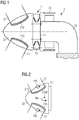
- the bearing is a two-row tapered roller bearing so that each bearing ring - inner ring and outer ring - has two raceways or seats.
- a raceway closest to the hub is referred to as an upwind raceway, and a raceway furthest from the hub is referred to as a downwind raceway.
- the raceways are angled in a "V" formation, as will become clear from the diagrams.
- the inventive method may be performed as part of a final grinding procedure.
- the bearing ring to be machined or ground will already have been finished to a high level of precision, and only a very small amount of material - e.g. only 100 ⁇ m or less - will be removed in the final machining stage.
- a grinding pattern is previously determined for the entire bearing ring, whereby the grinding depth for each local hard zone and each intermediate region (a region between local hard zones) is determined in advance.
- a grinding depth is to be understood as the depth to which material is to be removed from a local hard zone.
- the desired grinding pattern may comprise an alternating pattern of x and y, where x > y, and whereby x is the grinding depth within each of three blade regions, and y is the grinding depth in each of the intermediate regions.
- x is the grinding depth within each of three blade regions
- y is the grinding depth in each of the intermediate regions.
- the optimal grinding depth profile can be calculated by a suitable analysis tool such as advanced FEM analysis.
- the grinding depth for a surface is calculated on the basis of a specific predicted loading pattern that will arise from the rotor - i.e. the hub and blades - of that type of wind turbine.
- the specific predicted loading pattern established in the course of the invention takes a "fatigue characteristic load case" into consideration in order to achieve a best possible improvement in lifetime for a specific bearing type.
- the fatigue characteristic load case is related to a wind speed interval (e.g. a wind speed of 9 - 11 m/s for a wind turbine that will use that bearing type), and the relevant bearing parameters are generally optimised on the "worst case" assumption that the wind turbine will operate continually in this wind speed interval, at which the power output of the wind turbine is adjusted to its nominal value.
- the inventive method also effectively eliminates or minimizes any local hard zones in a wind turbine main bearing.
- a representative rotor position for obtaining the specific predicted loading pattern in the bearing is a position with one blade pointing vertically downwards, and the other two blades pointing upward and outward. This position is known as the "bunny" position since it is similar to the nose section of a rabbit. In the case of a three-blade rotor, this position is reached three times during each full revolution of the rotor.
- This grinding pattern favourably allows the bearing to operate, to a large extent, without local hard zones during a high number of operational hours resulting in lower bearing lifetime consumption.
- the deeper grinding depth (x) within a blade region preferably exceeds the shallower grinding depth (y) by a few microns, for example by 30 - 100 ⁇ m in the case of a main bearing with a diameter of 2 - 4 m.
- the grinding surface can be any surface of a bearing ring that is subject to uneven loading as the rotor rotates. This uneven loading may apply to a flange of the bearing, for example, and the flange surface can be ground using the inventive method after identifying the blade regions on that flange surface.
- a grinding surface is the raceway of a bearing ring.
- material is preferably removed from the raceway in a blade region to achieve an essentially constant bearing ring thickness over the blade region.
- the grinding wheel is controlled to achieve a smooth transition between a local hard zone and a neighbouring region.
- the grinding wheel could be controlled to obtain a movement up and down along on axis perpendicular to a raceway of the bearing ring while the bearing ring is being turned as it rests on a horizontal turning table.
- the grinding wheel position and position of bearing ring on the turning table are fully correlated via a control unit, to ensure a very precise grinding pattern.
- the grinding wheel is shifted slightly inwards or outwards to a new position corresponding to a different diameter.
- the grinding process in the circumferential direction is then repeated. This grinding process continues until the complete raceway has been ground to give the desired profile.
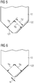
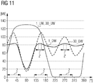
- a first curve 30_UW shows the roller forces for the upwind race.
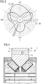
- Fig 6 shows results of a second embodiment of the inventive method when applied to grind the downwind raceway 122 of the outer ring 12 of the main bearing 1 of a direct-drive wind turbine.
- the downwind raceway 122 of the outer ring 12 has been ground to achieve an angular correction in the blade regions, with the ring thickness being reduced in a linear and gradual manner from the outer circumference of the raceway to the inner circumference of the raceway.
- the grinding is performed to take into account any underlying profile of the raceway 122 in order to maintain that underlying profile over the local hard zone also.
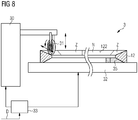
- Fig 7 shows a simplified plan view of an embodiment of the inventive grinding assembly.
- the bearing ring to be processed - in this case the outer bearing ring 12 of a wind turbine main bearing - is shown resting on a flat support such as a turning table 32.
- the turning table 32 can rotate the bearing ring 12 about its axis of rotation R.
- Three blade regions Z have been previously identified for this bearing ring 12. These are indicated by the dotted lines in the diagram, and it will be understood that these virtual positions may be defined in a suitable coordinate system that can be understood by a control unit of the grinding assembly.
- the top mark 19 of the bearing can be used to define the position of the bearing in that coordinate system. Any relevant data can be provided to a control program of the control unit in the usual manner.
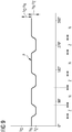
- Fig 9 illustrates a greatly simplified grinding pattern P or machining depth profile P achieved using the inventive method.
- the diagram serves to illustrate the final grinding pattern, and shows the alternating "deeper" regions corresponding to local hard zones Z, and nominal or shallower regions that correspond to intermediate or non-blade regions N.
- the diagram is not drawn to scale: the circumference of the bearing ring (from 0° to 360°) can be in the region of 12 m, while the grinding depth from the initial level h 0 to the final depth h N in a non-blade region N may be less than two tenths of a millimetre (i.e.
- the critical hard zones Z associated with uneven roller loading in the conventionally ground bearing are also indicated in the diagram, and a local hard zone Z can extend over about 30° - 40°.
- the maximum roller forces are significantly higher than the roller forces in the intermediate regions.
- the roller forces will be much more evenly distributed over the circumference of the bearing (rollers at the intermediate regions will now carry more load) and the maximum roller forces will be strongly reduced, indicated by the much smaller local hard zones Z' extending over only a few degrees at most.
- These smaller local hard zones Z' may be so small as to be negligible. This reduction in roller loading leads to bearing lifetime improvements in the range of 10% - 30%.
Landscapes
- Engineering & Computer Science (AREA)
- General Engineering & Computer Science (AREA)
- Mechanical Engineering (AREA)
- Manufacturing & Machinery (AREA)
- Rolling Contact Bearings (AREA)
Claims (15)
- Verfahren zum Bearbeiten eines Lagerrings (11, 12) eines Windturbinenlagers (1), wobei das Verfahren folgende Schritte umfasst:- Identifizieren einer Anzahl lokaler harter Zonen (Z) an einer Fläche (112, 122, 14) des Lagerrings (11, 12), wobei es sich bei einer harten Zone (Z) um einen Bereich handelt, in dem es im Vergleich zu den benachbarten Gebieten zu einer wesentlich höheren Belastung kommt, und- Entfernen von Material von der Fläche (112, 122, 14), so dass eine Lagerringdicke (hZ) in einer lokalen harten Zone (Z) geringer ist als eine Lagerringdicke (hN) außerhalb einer lokalen harten Zone (Z).
- Verfahren nach Anspruch 1, wobei es sich bei einer Fläche (112, 122) um eine Laufbahn (112, 122) des Lagerrings (11, 12) handelt.
- Verfahren nach Anspruch 1 oder 2, wobei es sich bei einer Fläche (14) um eine Flanschfläche (14) eines Lagerrings (12) handelt.
- Verfahren nach einem der vorhergehenden Ansprüche, wobei sich die Position einer lokalen harten Zone (Z) auf die Position einer Laufschaufel (21) in Bezug auf den Lagerring (11, 12) bezieht.
- Verfahren nach einem der vorhergehenden Ansprüche, das ein Bestimmen eines Bearbeitungstiefenprofils (P) entlang der Fläche umfasst.
- Verfahren nach einem der vorhergehenden Ansprüche, wobei Lagerringdicken (hZ, hN) und/oder ein Bearbeitungstiefenprofil (P) auf der Grundlage von Belastungswerten (30_DW) für den Windturbinenrotor bestimmt werden.
- Verfahren nach einem der vorhergehenden Ansprüche, wobei in einer lokalen harten Zone (Z) Material so von der Lagerfläche (112, 122, 14) entfernt wird, dass eine Winkelkorrektur für die Fläche (112, 122, 14) in der lokalen harten Zone (Z) bewirkt wird.
- Bearbeitungsbaugruppe (3), die Folgendes umfasst:- eine Auflage (32), die so ausgelegt ist, dass sie einen Lagerring (11, 12) einer Windturbine (2) bei einem Bearbeitungsvorgang hält,- ein Bearbeitungswerkzeug (31), das so angeordnet ist, dass es Material von einer Bearbeitungsfläche (112, 122, 14) des Lagerrings (11, 12) entfernt,- eine Steuereinheit (33), die so ausgelegt ist, dass sie zumindest das Bearbeitungswerkzeug (31) steuert, undwobei die Steuereinheit (33) so ausgelegt ist, dass sie Informationen (D) empfängt, die die Lage einer oder mehrerer lokaler harter Zonen (Z) an der Bearbeitungsfläche (112, 122, 14) bestimmen, wobei es sich bei einer harten Zone (Z) um einen Bereich handelt, in dem es im Vergleich zu den benachbarten Gebieten zu einer wesentlich höheren Belastung kommt, und das Bearbeitungswerkzeug (31) so steuert, dass es die Lagerringdicke in einer lokalen harten Zone (Z) stärker verringert als zwischen lokalen harten Zonen (Z), und/oder wobei die Bearbeitungsbaugruppe (3) eine Anzahl Verformungsmittel (35) umfasst, die so angeordnet sind, dass sie eine Anzahl lokaler harter Zonen (Z) näher zu dem Bearbeitungswerkzeug (31) bringen.
- Bearbeitungsbaugruppe nach Anspruch 8, wobei die Steuereinheit (33) ferner so ausgelegt ist, dass sie eine Relativbewegung zwischen dem Bearbeitungswerkzeug (31) und dem Lagerring (11, 12) bewirkt.
- Bearbeitungsbaugruppe nach Anspruch 8 oder 9, wobei die Auflage (32) drehbar und die Steuereinheit (33) ferner so ausgelegt ist, dass sie eine Drehung der Auflage (32) steuert.
- Bearbeitungsbaugruppe nach einem der Ansprüche 8 bis 10, wobei die Auflage (32) einen Auflagetisch (32) umfasst, der so angeordnet ist, dass er den Lagerring (11, 12) in horizontaler Position trägt.
- Bearbeitungsbaugruppe nach einem der Ansprüche 8 bis 11, wobei das Verformungsmittel (35) eine Anzahl Abstandhalter (35) umfasst, die in einer Position, die einer lokalen harten Zone (Z) entspricht, unter dem Lagerring (11, 12) angeordnet sind.
- Windturbinenlager (1) mit einem Lagerinnenring (11) und einem Lageraußenring (12), und wobei mindestens eine Schleiffläche (112, 122, 14) eines Lagerrings (11, 12) unter Verwendung des Verfahrens nach einem der Ansprüche 1 bis 7 geschliffen ist.
- Windturbine (2), die Folgendes umfasst:- mehrere Rotorblätter (21), die an einer Nabe (22) angebracht sind,- einen Generator mit einem außenliegenden Rotor und einem innenliegenden Stator und- ein Lager (1) mit einem festen Lagerinnenring (11) und einem drehbaren Lageraußenring (12), die so angeordnet sind, dass sie die Nabe (21) mit dem Generatorrotor verbinden,dadurch gekennzeichnet, dass ein Lagerring (11, 12) unter Verwendung des Verfahrens nach einem der Ansprüche 1 bis 7 hergestellt ist.
- Computerprogrammprodukt, das ein Computerprogramm umfasst, welches sich direkt in einen Speicher einer Steuereinheit einer Bearbeitungsbaugruppe (3) nach einem der Ansprüche 8 bis 13 laden lässt und Programmelemente umfasst, die Schritte des Verfahrens nach einem der Ansprüche 1 bis 7 durchführen, wenn das Computerprogramm von der Steuereinheit der Bearbeitungsbaugruppe (3) ausgeführt wird.
Applications Claiming Priority (2)
| Application Number | Priority Date | Filing Date | Title |
|---|---|---|---|
| DE102017204340 | 2017-03-15 | ||
| PCT/EP2018/050042 WO2018166661A1 (en) | 2017-03-15 | 2018-01-02 | Method of finishing a bearing ring |
Publications (2)
| Publication Number | Publication Date |
|---|---|
| EP3577360A1 EP3577360A1 (de) | 2019-12-11 |
| EP3577360B1 true EP3577360B1 (de) | 2021-03-17 |
Family
ID=61022298
Family Applications (1)
| Application Number | Title | Priority Date | Filing Date |
|---|---|---|---|
| EP18701091.3A Active EP3577360B1 (de) | 2017-03-15 | 2018-01-02 | Verfahren zum endbearbeiten eines lagerringes |
Country Status (5)
| Country | Link |
|---|---|
| US (1) | US11261915B2 (de) |
| EP (1) | EP3577360B1 (de) |
| CN (1) | CN110621895B (de) |
| DK (1) | DK3577360T3 (de) |
| WO (1) | WO2018166661A1 (de) |
Families Citing this family (3)
| Publication number | Priority date | Publication date | Assignee | Title |
|---|---|---|---|---|
| EP3577360B1 (de) | 2017-03-15 | 2021-03-17 | Siemens Gamesa Renewable Energy A/S | Verfahren zum endbearbeiten eines lagerringes |
| DE102019113897A1 (de) * | 2019-05-24 | 2020-11-26 | Liebherr-Components Biberach Gmbh | Wälzlager sowie Materialumschlags- und/oder Baumaschine mit einem solchen Wälzlager |
| CN119731431A (zh) * | 2023-07-26 | 2025-03-28 | 铁姆肯公司 | 用于风力涡轮主轴的轴承布置 |
Family Cites Families (13)
| Publication number | Priority date | Publication date | Assignee | Title |
|---|---|---|---|---|
| JPH065090B2 (ja) * | 1989-12-12 | 1994-01-19 | 日本精工株式会社 | ころがり軸受およびその製造方法 |
| US5286117A (en) | 1992-08-17 | 1994-02-15 | Ntn Corporation | Bearing with asymmetrical flexible section |
| US6616338B2 (en) * | 2001-06-13 | 2003-09-09 | Emerson Power Transmission Manufacturing, L.P. | Extended load zone bearing |
| JP2005090680A (ja) | 2003-09-19 | 2005-04-07 | Koyo Seiko Co Ltd | 転がり軸受部品およびその製造方法 |
| SE0302706L (sv) | 2003-10-14 | 2005-01-25 | Skf Ab | En metod för åstadkommande av förbättrade rullkontaktytor |
| JP2005325854A (ja) * | 2004-05-12 | 2005-11-24 | Ntn Corp | 硬質クロムメッキ部品の製造方法およびそれにより製造された部品 |
| BRPI0621045A2 (pt) | 2006-01-23 | 2011-11-29 | Vestas Wind Sys As | mancal, turbina eólica, método para a fabricação de um mancal, e uso de um mancal |
| US20110311362A1 (en) | 2008-12-04 | 2011-12-22 | Jochen Corts | Compound Steel Bearings and Methods of Manufacturing |
| JP5752351B2 (ja) * | 2009-12-02 | 2015-07-22 | Ntn株式会社 | 加工方法および軸受 |
| WO2013088201A1 (en) * | 2011-12-14 | 2013-06-20 | AMSC Austria GmbH | Bearing, wind energy converter and method of manufacturing a bearing |
| GB2514845B (en) | 2013-06-07 | 2019-11-13 | Equinor Energy As | Wind turbine control |
| US20160108895A1 (en) | 2014-10-17 | 2016-04-21 | General Electric Company | Method for machining a shaft and apparatus made thereby |
| EP3577360B1 (de) | 2017-03-15 | 2021-03-17 | Siemens Gamesa Renewable Energy A/S | Verfahren zum endbearbeiten eines lagerringes |
-
2018
- 2018-01-02 EP EP18701091.3A patent/EP3577360B1/de active Active
- 2018-01-02 DK DK18701091.3T patent/DK3577360T3/da active
- 2018-01-02 CN CN201880032586.6A patent/CN110621895B/zh active Active
- 2018-01-02 US US16/493,891 patent/US11261915B2/en active Active
- 2018-01-02 WO PCT/EP2018/050042 patent/WO2018166661A1/en not_active Ceased
Non-Patent Citations (1)
| Title |
|---|
| None * |
Also Published As
| Publication number | Publication date |
|---|---|
| CN110621895B (zh) | 2022-06-03 |
| WO2018166661A1 (en) | 2018-09-20 |
| US11261915B2 (en) | 2022-03-01 |
| EP3577360A1 (de) | 2019-12-11 |
| US20200088238A1 (en) | 2020-03-19 |
| CN110621895A (zh) | 2019-12-27 |
| DK3577360T3 (da) | 2021-05-03 |
Similar Documents
| Publication | Publication Date | Title |
|---|---|---|
| EP3276192B1 (de) | Lageranordnung | |
| CN103502664B (zh) | 轴向-径向滚动轴承以及具有该轴承的风力发电机 | |
| US9181982B2 (en) | Blade bearing with support structure having non-uniform stiffness and method manufacture | |
| EP3577360B1 (de) | Verfahren zum endbearbeiten eines lagerringes | |
| EP3460268B1 (de) | Axiallager für eine windturbine | |
| EP2372146B1 (de) | Windturbine und Walzlager für eine Windturbine | |
| US10458469B2 (en) | Bearing unit | |
| EP2541049B1 (de) | Nabenanordnung zur Verwendung mit einer Windturbine und Herstellungsverfahren dafür | |
| EP3428449B1 (de) | Antriebsstrang für eine windkraftanlage und verfahren zur positionierung eines hauptlagers des antriebsstrangs | |
| US10794422B1 (en) | System and method for assembling a slewing ring bearing with a predetermined preload | |
| WO2018153419A1 (en) | Wind turbine main rotor arrangement having improved bearing abutment configuration | |
| CN113468691B (zh) | 风力发电机组的传动轴系的设计方法 | |
| CN119572637B (zh) | 一种风电轴系支撑结构及其游隙配磨方法 | |
| US20130270834A1 (en) | Wind turbine generator with a stator support structure | |
| EP2679815A1 (de) | Rotationsanordnung für Windturbine und Windturbine mit solch einer Rotationsanordnung | |
| JP5951877B2 (ja) | 軸受構造及び風力発電装置 | |
| EP3872334A1 (de) | Verfahren zur verlängerung der blattlagerlebensdauer sowie blattlager | |
| EP4607050A1 (de) | Hauptlagereinheit | |
| JP2006177504A (ja) | ダイレクトドライブモータ | |
| US20250012325A1 (en) | An angular contact self-aligning toroidal rolling element bearing | |
| EP4459147A1 (de) | Lagerring, lager, windturbine und verfahren zur herstellung eines lagerrings | |
| US11873864B2 (en) | Method for increasing the load-bearing capacity, and rolling device for hard rolling a surface-hardened rolling-bearing raceway | |
| US20230296077A1 (en) | Wind turbine operation in extreme wind conditions | |
| DK202530137A1 (en) | Wind turbine main shaft arrangement | |
| JP2024131742A (ja) | 軸受装置 |
Legal Events
| Date | Code | Title | Description |
|---|---|---|---|
| STAA | Information on the status of an ep patent application or granted ep patent |
Free format text: STATUS: UNKNOWN |
|
| STAA | Information on the status of an ep patent application or granted ep patent |
Free format text: STATUS: THE INTERNATIONAL PUBLICATION HAS BEEN MADE |
|
| PUAI | Public reference made under article 153(3) epc to a published international application that has entered the european phase |
Free format text: ORIGINAL CODE: 0009012 |
|
| STAA | Information on the status of an ep patent application or granted ep patent |
Free format text: STATUS: REQUEST FOR EXAMINATION WAS MADE |
|
| 17P | Request for examination filed |
Effective date: 20190904 |
|
| AK | Designated contracting states |
Kind code of ref document: A1 Designated state(s): AL AT BE BG CH CY CZ DE DK EE ES FI FR GB GR HR HU IE IS IT LI LT LU LV MC MK MT NL NO PL PT RO RS SE SI SK SM TR |
|
| AX | Request for extension of the european patent |
Extension state: BA ME |
|
| DAV | Request for validation of the european patent (deleted) | ||
| DAX | Request for extension of the european patent (deleted) | ||
| GRAP | Despatch of communication of intention to grant a patent |
Free format text: ORIGINAL CODE: EPIDOSNIGR1 |
|
| STAA | Information on the status of an ep patent application or granted ep patent |
Free format text: STATUS: GRANT OF PATENT IS INTENDED |
|
| INTG | Intention to grant announced |
Effective date: 20201112 |
|
| GRAS | Grant fee paid |
Free format text: ORIGINAL CODE: EPIDOSNIGR3 |
|
| GRAA | (expected) grant |
Free format text: ORIGINAL CODE: 0009210 |
|
| STAA | Information on the status of an ep patent application or granted ep patent |
Free format text: STATUS: THE PATENT HAS BEEN GRANTED |
|
| AK | Designated contracting states |
Kind code of ref document: B1 Designated state(s): AL AT BE BG CH CY CZ DE DK EE ES FI FR GB GR HR HU IE IS IT LI LT LU LV MC MK MT NL NO PL PT RO RS SE SI SK SM TR |
|
| REG | Reference to a national code |
Ref country code: GB Ref legal event code: FG4D |
|
| REG | Reference to a national code |
Ref country code: CH Ref legal event code: EP |
|
| REG | Reference to a national code |
Ref country code: DE Ref legal event code: R096 Ref document number: 602018014035 Country of ref document: DE |
|
| REG | Reference to a national code |
Ref country code: IE Ref legal event code: FG4D |
|
| REG | Reference to a national code |
Ref country code: AT Ref legal event code: REF Ref document number: 1372507 Country of ref document: AT Kind code of ref document: T Effective date: 20210415 |
|
| REG | Reference to a national code |
Ref country code: DK Ref legal event code: T3 Effective date: 20210428 |
|
| REG | Reference to a national code |
Ref country code: SE Ref legal event code: TRGR |
|
| REG | Reference to a national code |
Ref country code: LT Ref legal event code: MG9D |
|
| PG25 | Lapsed in a contracting state [announced via postgrant information from national office to epo] |
Ref country code: FI Free format text: LAPSE BECAUSE OF FAILURE TO SUBMIT A TRANSLATION OF THE DESCRIPTION OR TO PAY THE FEE WITHIN THE PRESCRIBED TIME-LIMIT Effective date: 20210317 Ref country code: GR Free format text: LAPSE BECAUSE OF FAILURE TO SUBMIT A TRANSLATION OF THE DESCRIPTION OR TO PAY THE FEE WITHIN THE PRESCRIBED TIME-LIMIT Effective date: 20210618 Ref country code: HR Free format text: LAPSE BECAUSE OF FAILURE TO SUBMIT A TRANSLATION OF THE DESCRIPTION OR TO PAY THE FEE WITHIN THE PRESCRIBED TIME-LIMIT Effective date: 20210317 Ref country code: BG Free format text: LAPSE BECAUSE OF FAILURE TO SUBMIT A TRANSLATION OF THE DESCRIPTION OR TO PAY THE FEE WITHIN THE PRESCRIBED TIME-LIMIT Effective date: 20210617 Ref country code: NO Free format text: LAPSE BECAUSE OF FAILURE TO SUBMIT A TRANSLATION OF THE DESCRIPTION OR TO PAY THE FEE WITHIN THE PRESCRIBED TIME-LIMIT Effective date: 20210617 |
|
| REG | Reference to a national code |
Ref country code: AT Ref legal event code: MK05 Ref document number: 1372507 Country of ref document: AT Kind code of ref document: T Effective date: 20210317 |
|
| REG | Reference to a national code |
Ref country code: NL Ref legal event code: MP Effective date: 20210317 |
|
| PG25 | Lapsed in a contracting state [announced via postgrant information from national office to epo] |
Ref country code: RS Free format text: LAPSE BECAUSE OF FAILURE TO SUBMIT A TRANSLATION OF THE DESCRIPTION OR TO PAY THE FEE WITHIN THE PRESCRIBED TIME-LIMIT Effective date: 20210317 Ref country code: LV Free format text: LAPSE BECAUSE OF FAILURE TO SUBMIT A TRANSLATION OF THE DESCRIPTION OR TO PAY THE FEE WITHIN THE PRESCRIBED TIME-LIMIT Effective date: 20210317 |
|
| PG25 | Lapsed in a contracting state [announced via postgrant information from national office to epo] |
Ref country code: NL Free format text: LAPSE BECAUSE OF FAILURE TO SUBMIT A TRANSLATION OF THE DESCRIPTION OR TO PAY THE FEE WITHIN THE PRESCRIBED TIME-LIMIT Effective date: 20210317 |
|
| PG25 | Lapsed in a contracting state [announced via postgrant information from national office to epo] |
Ref country code: EE Free format text: LAPSE BECAUSE OF FAILURE TO SUBMIT A TRANSLATION OF THE DESCRIPTION OR TO PAY THE FEE WITHIN THE PRESCRIBED TIME-LIMIT Effective date: 20210317 Ref country code: CZ Free format text: LAPSE BECAUSE OF FAILURE TO SUBMIT A TRANSLATION OF THE DESCRIPTION OR TO PAY THE FEE WITHIN THE PRESCRIBED TIME-LIMIT Effective date: 20210317 Ref country code: LT Free format text: LAPSE BECAUSE OF FAILURE TO SUBMIT A TRANSLATION OF THE DESCRIPTION OR TO PAY THE FEE WITHIN THE PRESCRIBED TIME-LIMIT Effective date: 20210317 Ref country code: SM Free format text: LAPSE BECAUSE OF FAILURE TO SUBMIT A TRANSLATION OF THE DESCRIPTION OR TO PAY THE FEE WITHIN THE PRESCRIBED TIME-LIMIT Effective date: 20210317 Ref country code: AT Free format text: LAPSE BECAUSE OF FAILURE TO SUBMIT A TRANSLATION OF THE DESCRIPTION OR TO PAY THE FEE WITHIN THE PRESCRIBED TIME-LIMIT Effective date: 20210317 |
|
| PG25 | Lapsed in a contracting state [announced via postgrant information from national office to epo] |
Ref country code: IS Free format text: LAPSE BECAUSE OF FAILURE TO SUBMIT A TRANSLATION OF THE DESCRIPTION OR TO PAY THE FEE WITHIN THE PRESCRIBED TIME-LIMIT Effective date: 20210717 Ref country code: PT Free format text: LAPSE BECAUSE OF FAILURE TO SUBMIT A TRANSLATION OF THE DESCRIPTION OR TO PAY THE FEE WITHIN THE PRESCRIBED TIME-LIMIT Effective date: 20210719 Ref country code: PL Free format text: LAPSE BECAUSE OF FAILURE TO SUBMIT A TRANSLATION OF THE DESCRIPTION OR TO PAY THE FEE WITHIN THE PRESCRIBED TIME-LIMIT Effective date: 20210317 Ref country code: RO Free format text: LAPSE BECAUSE OF FAILURE TO SUBMIT A TRANSLATION OF THE DESCRIPTION OR TO PAY THE FEE WITHIN THE PRESCRIBED TIME-LIMIT Effective date: 20210317 Ref country code: SK Free format text: LAPSE BECAUSE OF FAILURE TO SUBMIT A TRANSLATION OF THE DESCRIPTION OR TO PAY THE FEE WITHIN THE PRESCRIBED TIME-LIMIT Effective date: 20210317 |
|
| REG | Reference to a national code |
Ref country code: DE Ref legal event code: R097 Ref document number: 602018014035 Country of ref document: DE |
|
| PLBE | No opposition filed within time limit |
Free format text: ORIGINAL CODE: 0009261 |
|
| STAA | Information on the status of an ep patent application or granted ep patent |
Free format text: STATUS: NO OPPOSITION FILED WITHIN TIME LIMIT |
|
| PG25 | Lapsed in a contracting state [announced via postgrant information from national office to epo] |
Ref country code: ES Free format text: LAPSE BECAUSE OF FAILURE TO SUBMIT A TRANSLATION OF THE DESCRIPTION OR TO PAY THE FEE WITHIN THE PRESCRIBED TIME-LIMIT Effective date: 20210317 Ref country code: AL Free format text: LAPSE BECAUSE OF FAILURE TO SUBMIT A TRANSLATION OF THE DESCRIPTION OR TO PAY THE FEE WITHIN THE PRESCRIBED TIME-LIMIT Effective date: 20210317 |
|
| 26N | No opposition filed |
Effective date: 20211220 |
|
| PG25 | Lapsed in a contracting state [announced via postgrant information from national office to epo] |
Ref country code: SI Free format text: LAPSE BECAUSE OF FAILURE TO SUBMIT A TRANSLATION OF THE DESCRIPTION OR TO PAY THE FEE WITHIN THE PRESCRIBED TIME-LIMIT Effective date: 20210317 |
|
| PG25 | Lapsed in a contracting state [announced via postgrant information from national office to epo] |
Ref country code: IT Free format text: LAPSE BECAUSE OF FAILURE TO SUBMIT A TRANSLATION OF THE DESCRIPTION OR TO PAY THE FEE WITHIN THE PRESCRIBED TIME-LIMIT Effective date: 20210317 |
|
| PG25 | Lapsed in a contracting state [announced via postgrant information from national office to epo] |
Ref country code: IS Free format text: LAPSE BECAUSE OF FAILURE TO SUBMIT A TRANSLATION OF THE DESCRIPTION OR TO PAY THE FEE WITHIN THE PRESCRIBED TIME-LIMIT Effective date: 20210717 |
|
| PG25 | Lapsed in a contracting state [announced via postgrant information from national office to epo] |
Ref country code: MC Free format text: LAPSE BECAUSE OF FAILURE TO SUBMIT A TRANSLATION OF THE DESCRIPTION OR TO PAY THE FEE WITHIN THE PRESCRIBED TIME-LIMIT Effective date: 20210317 |
|
| REG | Reference to a national code |
Ref country code: CH Ref legal event code: PL |
|
| REG | Reference to a national code |
Ref country code: BE Ref legal event code: MM Effective date: 20220131 |
|
| PG25 | Lapsed in a contracting state [announced via postgrant information from national office to epo] |
Ref country code: LU Free format text: LAPSE BECAUSE OF NON-PAYMENT OF DUE FEES Effective date: 20220102 |
|
| PG25 | Lapsed in a contracting state [announced via postgrant information from national office to epo] |
Ref country code: BE Free format text: LAPSE BECAUSE OF NON-PAYMENT OF DUE FEES Effective date: 20220131 |
|
| PG25 | Lapsed in a contracting state [announced via postgrant information from national office to epo] |
Ref country code: LI Free format text: LAPSE BECAUSE OF NON-PAYMENT OF DUE FEES Effective date: 20220131 Ref country code: CH Free format text: LAPSE BECAUSE OF NON-PAYMENT OF DUE FEES Effective date: 20220131 |
|
| PG25 | Lapsed in a contracting state [announced via postgrant information from national office to epo] |
Ref country code: IE Free format text: LAPSE BECAUSE OF NON-PAYMENT OF DUE FEES Effective date: 20220102 |
|
| PG25 | Lapsed in a contracting state [announced via postgrant information from national office to epo] |
Ref country code: MK Free format text: LAPSE BECAUSE OF FAILURE TO SUBMIT A TRANSLATION OF THE DESCRIPTION OR TO PAY THE FEE WITHIN THE PRESCRIBED TIME-LIMIT Effective date: 20210317 Ref country code: CY Free format text: LAPSE BECAUSE OF FAILURE TO SUBMIT A TRANSLATION OF THE DESCRIPTION OR TO PAY THE FEE WITHIN THE PRESCRIBED TIME-LIMIT Effective date: 20210317 |
|
| PG25 | Lapsed in a contracting state [announced via postgrant information from national office to epo] |
Ref country code: HU Free format text: LAPSE BECAUSE OF FAILURE TO SUBMIT A TRANSLATION OF THE DESCRIPTION OR TO PAY THE FEE WITHIN THE PRESCRIBED TIME-LIMIT; INVALID AB INITIO Effective date: 20180102 |
|
| PG25 | Lapsed in a contracting state [announced via postgrant information from national office to epo] |
Ref country code: MT Free format text: LAPSE BECAUSE OF FAILURE TO SUBMIT A TRANSLATION OF THE DESCRIPTION OR TO PAY THE FEE WITHIN THE PRESCRIBED TIME-LIMIT Effective date: 20210317 |
|
| PGFP | Annual fee paid to national office [announced via postgrant information from national office to epo] |
Ref country code: DE Payment date: 20250129 Year of fee payment: 8 |
|
| PGFP | Annual fee paid to national office [announced via postgrant information from national office to epo] |
Ref country code: DK Payment date: 20250127 Year of fee payment: 8 |
|
| PGFP | Annual fee paid to national office [announced via postgrant information from national office to epo] |
Ref country code: SE Payment date: 20250127 Year of fee payment: 8 |
|
| PGFP | Annual fee paid to national office [announced via postgrant information from national office to epo] |
Ref country code: FR Payment date: 20250127 Year of fee payment: 8 |
|
| PGFP | Annual fee paid to national office [announced via postgrant information from national office to epo] |
Ref country code: GB Payment date: 20250121 Year of fee payment: 8 |
|
| PG25 | Lapsed in a contracting state [announced via postgrant information from national office to epo] |
Ref country code: TR Free format text: LAPSE BECAUSE OF FAILURE TO SUBMIT A TRANSLATION OF THE DESCRIPTION OR TO PAY THE FEE WITHIN THE PRESCRIBED TIME-LIMIT Effective date: 20210317 |