EP3576885B1 - Prägesystem - Google Patents
Prägesystem Download PDFInfo
- Publication number
- EP3576885B1 EP3576885B1 EP18713375.6A EP18713375A EP3576885B1 EP 3576885 B1 EP3576885 B1 EP 3576885B1 EP 18713375 A EP18713375 A EP 18713375A EP 3576885 B1 EP3576885 B1 EP 3576885B1
- Authority
- EP
- European Patent Office
- Prior art keywords
- embossing
- roller
- unit
- amplitude
- data
- Prior art date
- Legal status (The legal status is an assumption and is not a legal conclusion. Google has not performed a legal analysis and makes no representation as to the accuracy of the status listed.)
- Active
Links
- 238000004049 embossing Methods 0.000 title claims description 38
- 239000003292 glue Substances 0.000 claims description 38
- 238000004026 adhesive bonding Methods 0.000 claims description 24
- 238000000034 method Methods 0.000 claims description 6
- 238000009826 distribution Methods 0.000 claims description 5
- 238000012360 testing method Methods 0.000 claims description 5
- 230000002159 abnormal effect Effects 0.000 claims description 3
- 238000007774 anilox coating Methods 0.000 description 9
- 238000005461 lubrication Methods 0.000 description 6
- 230000015572 biosynthetic process Effects 0.000 description 5
- 239000000463 material Substances 0.000 description 4
- 238000005259 measurement Methods 0.000 description 4
- 238000011144 upstream manufacturing Methods 0.000 description 3
- 238000010521 absorption reaction Methods 0.000 description 2
- 230000004913 activation Effects 0.000 description 2
- 239000007788 liquid Substances 0.000 description 2
- 238000004519 manufacturing process Methods 0.000 description 2
- 238000013021 overheating Methods 0.000 description 2
- XLYOFNOQVPJJNP-UHFFFAOYSA-N water Substances O XLYOFNOQVPJJNP-UHFFFAOYSA-N 0.000 description 2
- 238000004804 winding Methods 0.000 description 2
- 230000002547 anomalous effect Effects 0.000 description 1
- 238000006243 chemical reaction Methods 0.000 description 1
- 239000002131 composite material Substances 0.000 description 1
- 238000010276 construction Methods 0.000 description 1
- 238000005520 cutting process Methods 0.000 description 1
- 230000003111 delayed effect Effects 0.000 description 1
- 230000001419 dependent effect Effects 0.000 description 1
- 238000001514 detection method Methods 0.000 description 1
- 238000010586 diagram Methods 0.000 description 1
- 230000006870 function Effects 0.000 description 1
- 230000007246 mechanism Effects 0.000 description 1
- 230000002093 peripheral effect Effects 0.000 description 1
- 238000003825 pressing Methods 0.000 description 1
- 230000008569 process Effects 0.000 description 1
- 230000009467 reduction Effects 0.000 description 1
- 230000004044 response Effects 0.000 description 1
- 238000007493 shaping process Methods 0.000 description 1
Images

Classifications
-
- B—PERFORMING OPERATIONS; TRANSPORTING
- B31—MAKING ARTICLES OF PAPER, CARDBOARD OR MATERIAL WORKED IN A MANNER ANALOGOUS TO PAPER; WORKING PAPER, CARDBOARD OR MATERIAL WORKED IN A MANNER ANALOGOUS TO PAPER
- B31F—MECHANICAL WORKING OR DEFORMATION OF PAPER, CARDBOARD OR MATERIAL WORKED IN A MANNER ANALOGOUS TO PAPER
- B31F1/00—Mechanical deformation without removing material, e.g. in combination with laminating
- B31F1/07—Embossing, i.e. producing impressions formed by locally deep-drawing, e.g. using rolls provided with complementary profiles
-
- B—PERFORMING OPERATIONS; TRANSPORTING
- B31—MAKING ARTICLES OF PAPER, CARDBOARD OR MATERIAL WORKED IN A MANNER ANALOGOUS TO PAPER; WORKING PAPER, CARDBOARD OR MATERIAL WORKED IN A MANNER ANALOGOUS TO PAPER
- B31F—MECHANICAL WORKING OR DEFORMATION OF PAPER, CARDBOARD OR MATERIAL WORKED IN A MANNER ANALOGOUS TO PAPER
- B31F1/00—Mechanical deformation without removing material, e.g. in combination with laminating
- B31F1/20—Corrugating; Corrugating combined with laminating to other layers
- B31F1/24—Making webs in which the channel of each corrugation is transverse to the web feed
- B31F1/26—Making webs in which the channel of each corrugation is transverse to the web feed by interengaging toothed cylinders cylinder constructions
- B31F1/28—Making webs in which the channel of each corrugation is transverse to the web feed by interengaging toothed cylinders cylinder constructions combined with uniting the corrugated webs to flat webs ; Making double-faced corrugated cardboard
- B31F1/2818—Glue application specially adapted therefor
-
- B—PERFORMING OPERATIONS; TRANSPORTING
- B31—MAKING ARTICLES OF PAPER, CARDBOARD OR MATERIAL WORKED IN A MANNER ANALOGOUS TO PAPER; WORKING PAPER, CARDBOARD OR MATERIAL WORKED IN A MANNER ANALOGOUS TO PAPER
- B31F—MECHANICAL WORKING OR DEFORMATION OF PAPER, CARDBOARD OR MATERIAL WORKED IN A MANNER ANALOGOUS TO PAPER
- B31F2201/00—Mechanical deformation of paper or cardboard without removing material
- B31F2201/07—Embossing
- B31F2201/0707—Embossing by tools working continuously
- B31F2201/0715—The tools being rollers
- B31F2201/0717—Methods and means for forming the embossments
-
- B—PERFORMING OPERATIONS; TRANSPORTING
- B31—MAKING ARTICLES OF PAPER, CARDBOARD OR MATERIAL WORKED IN A MANNER ANALOGOUS TO PAPER; WORKING PAPER, CARDBOARD OR MATERIAL WORKED IN A MANNER ANALOGOUS TO PAPER
- B31F—MECHANICAL WORKING OR DEFORMATION OF PAPER, CARDBOARD OR MATERIAL WORKED IN A MANNER ANALOGOUS TO PAPER
- B31F2201/00—Mechanical deformation of paper or cardboard without removing material
- B31F2201/07—Embossing
- B31F2201/0758—Characteristics of the embossed product
- B31F2201/0761—Multi-layered
- B31F2201/0764—Multi-layered the layers being nested
-
- B—PERFORMING OPERATIONS; TRANSPORTING
- B31—MAKING ARTICLES OF PAPER, CARDBOARD OR MATERIAL WORKED IN A MANNER ANALOGOUS TO PAPER; WORKING PAPER, CARDBOARD OR MATERIAL WORKED IN A MANNER ANALOGOUS TO PAPER
- B31F—MECHANICAL WORKING OR DEFORMATION OF PAPER, CARDBOARD OR MATERIAL WORKED IN A MANNER ANALOGOUS TO PAPER
- B31F2201/00—Mechanical deformation of paper or cardboard without removing material
- B31F2201/07—Embossing
- B31F2201/0771—Other aspects of the embossing operations
-
- B—PERFORMING OPERATIONS; TRANSPORTING
- B31—MAKING ARTICLES OF PAPER, CARDBOARD OR MATERIAL WORKED IN A MANNER ANALOGOUS TO PAPER; WORKING PAPER, CARDBOARD OR MATERIAL WORKED IN A MANNER ANALOGOUS TO PAPER
- B31F—MECHANICAL WORKING OR DEFORMATION OF PAPER, CARDBOARD OR MATERIAL WORKED IN A MANNER ANALOGOUS TO PAPER
- B31F2201/00—Mechanical deformation of paper or cardboard without removing material
- B31F2201/07—Embossing
- B31F2201/0779—Control
-
- B—PERFORMING OPERATIONS; TRANSPORTING
- B31—MAKING ARTICLES OF PAPER, CARDBOARD OR MATERIAL WORKED IN A MANNER ANALOGOUS TO PAPER; WORKING PAPER, CARDBOARD OR MATERIAL WORKED IN A MANNER ANALOGOUS TO PAPER
- B31F—MECHANICAL WORKING OR DEFORMATION OF PAPER, CARDBOARD OR MATERIAL WORKED IN A MANNER ANALOGOUS TO PAPER
- B31F2201/00—Mechanical deformation of paper or cardboard without removing material
- B31F2201/07—Embossing
- B31F2201/0784—Auxiliary operations
- B31F2201/0787—Applying adhesive
-
- B—PERFORMING OPERATIONS; TRANSPORTING
- B31—MAKING ARTICLES OF PAPER, CARDBOARD OR MATERIAL WORKED IN A MANNER ANALOGOUS TO PAPER; WORKING PAPER, CARDBOARD OR MATERIAL WORKED IN A MANNER ANALOGOUS TO PAPER
- B31F—MECHANICAL WORKING OR DEFORMATION OF PAPER, CARDBOARD OR MATERIAL WORKED IN A MANNER ANALOGOUS TO PAPER
- B31F5/00—Attaching together sheets, strips or webs; Reinforcing edges
- B31F5/04—Attaching together sheets, strips or webs; Reinforcing edges by exclusive use of adhesives
Definitions
- the present invention relates to an embossing system.
- the present invention relates to an embossing system in which glue is used to join together two or more webs of paper material to produce rolls of paper commonly called "logs" from which are obtained rolls of toilet paper, rolls of kitchen paper etc.
- logs of paper material from which are obtained, for example, rolls of toilet paper or rolls of kitchen paper
- the production of logs of paper material implies the feeding of a web of paper, formed by one or more superimposed layers, on a predetermined path along which various operations are performed before proceeding to the formation of the logs, including a transversal pre-incision of the web to form pre-cut lines which divide it into separable tear-off sheets.
- the formation of logs implies the use of cardboard tubes, commonly called “cores" on the surface of which a predetermined amount of glue is distributed to allow the paper web to be bonded onto the cores gradually introduced into the machine which produces the logs, machine commonly called “rewinder”.
- the formation of the logs also implies the use of winding rollers located at the cradle, which impose on each core to rotate about its longitudinal axis thus determining the winding of the web on the same core.
- One of the rollers is located below the cradle, while other rollers are placed above the cradle.
- the process ends when a predetermined number of sheets is wound on the core, with the gluing of a flap of the last sheet on the underlying sheet of the roll thus formed (so-called "closing flap" operation).
- the last sheet of the log being completed is separated from the first sheet of the next log, for example by a jet of compressed air directed towards a corresponding pre-cutting line.
- the log is downloaded from the rewinder.
- the patent EP1700805 describes a rewinding machine that operates according to the above operating scheme.
- the paper web used by the rewinding machine can be made up of several plies which are previously embossed and joined together by gluing in a unit comprising a predetermined number of embossing rollers to which is associated a gluing unit for distributing glue on at least one of the plies subjected to embossing.
- the gluing unit comprises an anilox roller which picks up the glue from a special intake tank and a cliche roller which receives by contact the glue from the anilox roller and distributes it onto the veil to be glued.
- the contact between the latter and the cliche roller causes overheating which, in particular, can damage the cliché roller.
- the systems based on the temperature control of the cliche roller are inadequate because they are delayed since the detection of overheating occurs when this phenomenon has already occurred.
- US5876530A discloses a glue application roll rotating at a given circumferential velocity is moved to touch a downstream side corrugating roll or an upper corrugating roll rotating at another circumferential velocity via a core paper and, in response to variation in vibration, noise, drive torque or pressing reaction force of the glue application roll caused thereby, a setting position of the glue application roll to the downstream side corrugating roll is adjusted, thus a gap between the glue application roll and the downstream side corrugating roll is maintained approximately at a thickness of the core paper.
- US6470294B1 discloses a system and a method for determining the rate of application of liquid glue to corrugated board on a corrugator.
- a sensor employing the principle of infrared absorption measures the amount of water on the surface of the glue roll upstream of the point of application of the glue to the corrugated board's medium.
- a second sensor employing the principle of infrared absorption measurers the amount of water on the surface of the glue roll downstream of the point of application of the glue to the corrugated board's medium.
- the two sensor's output signals are then converted into film thickness measurements.
- the downstream film thickness measurement is then subtracted from the upstream film thickness measurement to compute the reduction in film thickness caused by the intervening application of the glue to the medium.
- WO2004/096684 discloses an apparatus for causing paper webs to tear off within rewinding machines, the webs being provided, at regular intervals, with transverse perforation which subdivide the webs into sheets joined to each other but able to be separated in correspondence of said perforation lines.
- the apparatus comprises means to cause the tearing of the webs upon the passage of a perforation line which separates the last sheet of a log) in the course of formation from the first sheet of the next log to be formed.
- the tearing means are of pneumatic type able to direct a jet of compressed air towards the perforation line.
- US2001/047850 relates to a device for manufacturing a composite sheet comprising at least one corrugated sheet and at least one flat sheet that is glued to the wave peaks of the corrugated sheet, said device comprising at least one fluted roller for shaping and/or maintaining the shape of the corrugated sheet, said roller being covered with the corrugated sheet around a portion of its circumference during operation, and a gluing unit for applying a liquid glue used to attach the corrugated sheet to the flat sheet, with said gluing unit having a gluing roller whose outer surface is continuously coated with a glue film and whose axis is essentially parallel to that of the fluted roller, said gluing roller being driven at approximately the same peripheral speed as that of the fluted roller, and with it being possible, using means for moving the rollers closer together, to move said gluing roller, with its outer surface against the portion of the circumference of the fluted roller that is covered with the corrugated sheet, into a close-up position that allows the glue to be transmitted to the wave peaks of
- the main object of the present invention is to propose an embossing /gluing system provided with a particularly rapid and efficient control mechanism.
- the vibrations of the cliche roller during operation with a reference model previously formed in a testing phase of the unit in which the cliche roller is installed, having observed that the vibrations of said component may vary according to the amount of glue actually present on its surface.
- the reference model can be constructed by running the embosser in different regimes, i.e. under conditions of correct and respectively incorrect distribution of the glue on the cliche roller, detecting its vibrations.
- a sensor device detects the vibrations of the cliché roller and produces corresponding electrical signals which, converted into numerical data, are used by a control unit which compares them with the data detected and recorded in the reference model.
- the control unit If the instantaneous values detected during the use of the system differ from the previously acquired reference values, the control unit generates an electrical alarm signal that can be used to drive an acoustic and / or luminous signal and / or to control the stop of the plant or the slowing down of the units that form the plant itself until the correct operating conditions are restored.
- a sensor device is used, preferably the same device subsequently used when the system is in operation, suitable for producing electrical signals of amplitude and frequency related to the vibrations of the system under test.
- the operating unit (OU) schematically represented in Fig. 1 comprises a pair of embossing rollers with relative counter-rollers (G1, G2) arranged vertically overlapped, i.e. with the corresponding rotation axes horizontally oriented and aligned along the same vertical axis.
- the unit (OU) also comprises a glue distributor with a tank (T), an anilox roller (AR) and a cliché roller (CR) whose axes are parallel to those of the embossing rollers.
- the tank (T) contains the glue used to glue together two plies of paper material (VI, V2) supplied by respective reels placed on unwinders (not shown in the drawings) arranged upstream of the unit (UO) with respect to the direction (A) from which the same plies (VI, V2) come.
- the latters passing between the embossing rollers and the relative counter-rollers (G1, G2), are embossed.
- the anilox roller (AR) rotating around its own axis, picks up the glue from the tank (T) and transfers it to the cliche roller (CR) which, in turn, distributes it on the ply (V1) subjected to embossing by the respective roller and counter-roller (G1).
- the ply (V1) will therefore stick to the ply (V2) treated by the roller and by the counter-roller (G2) forming the web (W) that comes out of the unit (OU) along the direction (AW) to feed a rewinder (RW), prepared downstream, which wind the web (W) to produce logs destined to be cut transversely to obtain rolls of toilet paper, kitchen paper etc.
- the cliche roller and the anilox roller have different rotation speeds to allow the glue to be dosed differently depending on the product to be produced.
- the structure and operation of such an operating unit are known to those skilled in the art.
- the structure and operation of the rewinders as well as the structure and operation of the unwinders are also known.
- a ply (V2) is not embossed in the unit (OU) .
- the roller and the counter-roller of the couple (G2) form a guide device for the ply (V2) which remains smooth and is glued to the ply (V1) which is instead embossed.
- the gluing unit (T, AR, CR) is positioned on a respective support structure (S) which allows it to be placed in operative position (set-up in which the cliche roller CR is coupled to an embossing roller) and in inoperative position (set-up in which the cliché roller CR is spaced from the embossing roller to which it is instead approached in the operating phase).
- the aforesaid operating unit (OU) is controlled by a programmable control unit (1) which controls the motors (M1, M2) which determine the rotation of the embossing rollers and of the relative counter-rollers (G1, G2), the motors (MA, MC) of the anilox (AR) and cliche (CR) rollers, and the actuator (AS) which determines the movement of the mobile support (S) of the gluing unit (T, AR, CR).
- a sensor (2) able to detect the vibrations of the cliché roller (CR) is connected to a corresponding input of the control unit (1).
- said sensor (2) is an accelerometer of the SKF CMSS2200 type.
- this sensor (2) detects the vibrations of a bearing supporting one end of the cliche roller (CR) shaft in such a way as to detect the vibrations of the shaft itself.
- the sensor (2) produces electrical signals representative of the vibrations to which the cliche roller (CR) is subjected during its operation.
- the electrical signals produced by the sensor (2) are signals of amplitude and frequency determined by the vibrations of the cliché roller (CR).
- the operating unit (OU) is operated under normal conditions (i.e. under conditions of proper lubrication of the cliché roller CR which receives glue from the anilox roller AR in sufficient quantity to guarantee lubrication), and in conditions of poor lubrication (i.e. in conditions of insufficient lubrication of the cliche roller CR which receives glue from the anilox roller AR in insufficient quantity to guarantee a correct lubrication), detecting the vibrations of the cliche roller (CR) in each of these operating conditions specially reproduced.
- said vibrations are detected with the same sensor (2) subsequently used during operation of the system. Said measurements, i.e.
- a data file (DB) which is used by the control unit (1) as further indicated below.
- the file (DB) can be registered in a memory section of the control unit (1).
- both normal and abnormal operating conditions of the unit (OU) are reproduced and data of amplitude and / or frequency of electrical signals produced by the vibrations of the cliche roller (CR) are recorded by a transducer that converts such vibrations into electrical signals.
- the data thus recorded are then used as a reference model in the phase of actual productive use of the operational unit (OU).
- the control unit (1) continuously receives the data corresponding to the signals produced by the sensor (2) and compares them with the data of the file (DB). If the data related to the vibrations detected by the sensor (2) correspond to the data of the file (DB) representing anomalous operating conditions, the control unit (1) intervenes on the motors (M1, M2, MA, MC) to slow down the rotation of the rollers connected to them or also to stop the rotation thereof. In the latter case, the control unit (1) can also be programmed to drive the actuator (AS) so as to distance the gluing unit (T, AR, CR) from the embossing rollers.
- AS actuator
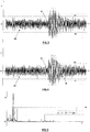
- Fig.3 schematically represents the time course of the electrical signal (SH) produced by the sensor (2) during operation (operational use phase) of the unit (OU).
- the dotted lines (UL, LL) represent the upper (UL) and lower (LL) limits of a field within which the amplitude (y) of the signal (SH) may vary over time (t) without the unit of control (1) generate any alarm signal.
- the values (UL, LL) are determined in the testing phase of the unit (OU) and represent two limit values of the signal amplitude (SH) detected in conditions of correct lubrication of the cliche roller (CR).
- the control unit (1) generates the alarm signal which determines the activation of the programmed procedure (slowing down or stopping the system).
- the control unit (1) can be programmed to generate said alarm signal if the signal trend (SH) is such that the limit values (UL, LL) are exceeded for a predetermined number (N) of times in a time interval ( ⁇ T) also preestablished.
- Fig.5 schematically represents the instantaneous values (a) of the signal produced by the sensor (2) as a function of the frequencies (f).
- a possible distribution DF
- aL limit value assumed as reference for the control unit (1), similarly to what previously stated with reference to the amplitude data of the signal produced by the sensor (2).
- an embossing system comprises:
Claims (7)
- Prägesystem, umfassend:- eine Prägeeinheit mit mindestens einer Prägewalze (G1; G2), die zum Prägen einer Papierbahn (V1; V2) angeordnet ist, die durch Verleimen mit einer weiteren Bahn (V2, V1) aneinandergefügt werden soll; und- eine Verleimeinheit, die der Prägeeinheit zugeordnet ist, mit einem Tank (T), der den Leim enthält, der verwendet wird, um das Verleimen durchzuführen, und einer Leimabgabevorrichtung (GD), die eine Klischeewalze (CR) umfasst, die dazu ausgelegt ist, durch Kontakt den in dem Tank (T) enthaltenen Leim auf einer der Bahnen (VI, V2) zu verteilen, während das Prägen durchgeführt wird, wobei sich die Klischeewalze (CR) mit einer vorbestimmten Winkelgeschwindigkeit um eine Achse (x) parallel zu der mindestens einen Prägewalze (G1; G2) dreht;- einen Sensor (2), der in der Lage ist, elektrische Signale zu erzeugen, deren Amplitude und/oder Frequenz mit den Vibrationen in Zusammenhang stehen, denen die Klischeewalze (CR) momentan ausgesetzt ist, während sich diese um die Achse (x) dreht;- eine Steuereinheit (1), die während des Betriebs des Systems momentane Daten der Amplitude und/oder Frequenz der von dem Sensor (2) erzeugten Signale empfängt und sie mit Referenzdaten vergleicht; dadurch gekennzeichnet, dass die Referenzdaten in einer Datei (DB) enthalten sind, die zuvor durch Testen der Prägeeinheit und der Verleimeinheit unter Bedingungen einer regelmäßigen bzw. unregelmäßigen Verteilung des Leims auf der Klischeewalze (CR) erhalten wurde, wobei die Referenzdaten aus einem ersten Satz von Amplituden- und/oder Frequenzdaten, die für normale Schwingungen repräsentativ sind, und einem zweiten Satz von Amplituden- und/oder Frequenzdaten, die für anormale Schwingungen repräsentativ sind, bestehen, wobei die Steuereinheit (1) so programmiert ist, dass sie ein Alarmsignal erzeugt, wenn mindestens ein momentaner Bezugspunkt der Amplitude und/oder Frequenz der von dem Sensor (2) erzeugten Signale mindestens einem Bezugspunkt der Amplitude und/oder Frequenz des zweiten Satzes entspricht.
- Prägesystem nach Anspruch 1, dadurch gekennzeichnet, dass die Daten des ersten und zweiten Datensatzes mittels des Sensors (2) erfasst werden, der die momentanen Daten in der Betriebsphase des Systems erzeugt.
- Prägesystem nach Anspruch 1, dadurch gekennzeichnet, dass der Sensor (2) die Vibrationen eines Lagers detektiert, das ein Ende der Klischeewalzenwelle in einer solchen Weise trägt, dass die Vibrationen der Welle selbst detektiert werden, während sich die Klischeewalze um die Drehachse (x) dreht.
- Prägen nach Anspruch 1, dadurch gekennzeichnet, dass das Alarmsignal ein Verfahren zum Verlangsamen oder Anhalten des von der Steuereinheit (1) gesteuerten Prägesystems aktiviert.
- Prägesystem nach Anspruch 1, wobei die Klischeewalze und die Prägewalzen von jeweiligen Antriebseinheiten (MC, M1, M2) angetrieben werden, dadurch gekennzeichnet, dass das Alarmsignal ein Verfahren zum Verlangsamen oder Anhalten der von der Steuereinheit (1) gesteuerten Antriebseinheiten aktiviert.
- Prägesystem nach Anspruch 1, wobei die Verleimeinheit auf einem entsprechenden Träger (S) montiert ist, der das Entfernen derselben von der Prägeeinheit mittels eines Stellantriebs (AS) ermöglicht, dadurch gekennzeichnet, dass das Alarmsignal den Stellantrieb (AS) aktiviert und so das Entfernen bestimmt.
- Prägesystem nach Anspruch 1, dadurch gekennzeichnet, dass die Steuereinheit (1) das Alarmsignal erzeugt, wenn die momentanen Daten der Amplitude und/oder Frequenz der vom Sensor (2) erzeugten Signale den Daten des zweiten Satzes für eine vorbestimmte Anzahl von Malen in einem ebenfalls vorbestimmten Zeitintervall entsprechen.
Priority Applications (2)
| Application Number | Priority Date | Filing Date | Title |
|---|---|---|---|
| PL18713375T PL3576885T3 (pl) | 2017-02-03 | 2018-01-23 | System wytłaczania |
| RS20201579A RS61354B1 (sr) | 2017-02-03 | 2018-01-23 | Sistem za utiskivanje |
Applications Claiming Priority (2)
| Application Number | Priority Date | Filing Date | Title |
|---|---|---|---|
| IT102017000011824A IT201700011824A1 (it) | 2017-02-03 | 2017-02-03 | Sistema di goffratura. |
| PCT/IT2018/000008 WO2018142434A1 (en) | 2017-02-03 | 2018-01-23 | Embossing system |
Publications (2)
| Publication Number | Publication Date |
|---|---|
| EP3576885A1 EP3576885A1 (de) | 2019-12-11 |
| EP3576885B1 true EP3576885B1 (de) | 2020-11-18 |
Family
ID=58779320
Family Applications (1)
| Application Number | Title | Priority Date | Filing Date |
|---|---|---|---|
| EP18713375.6A Active EP3576885B1 (de) | 2017-02-03 | 2018-01-23 | Prägesystem |
Country Status (11)
| Country | Link |
|---|---|
| US (1) | US11084243B2 (de) |
| EP (1) | EP3576885B1 (de) |
| JP (1) | JP2020506092A (de) |
| CN (1) | CN110087780B (de) |
| BR (1) | BR112019011440A2 (de) |
| ES (1) | ES2836728T3 (de) |
| IT (1) | IT201700011824A1 (de) |
| PL (1) | PL3576885T3 (de) |
| RS (1) | RS61354B1 (de) |
| RU (1) | RU2744409C2 (de) |
| WO (1) | WO2018142434A1 (de) |
Families Citing this family (1)
| Publication number | Priority date | Publication date | Assignee | Title |
|---|---|---|---|---|
| ITUB20160458A1 (it) * | 2016-01-25 | 2017-07-25 | Futura Spa | Sistema per la movimentazione di rulli goffratori |
Family Cites Families (13)
| Publication number | Priority date | Publication date | Assignee | Title |
|---|---|---|---|---|
| FR1455170A (fr) * | 1965-06-17 | 1966-04-01 | Marius Martin | Machine d'enduction à transfert contrôlé |
| JPS62251128A (ja) * | 1986-04-25 | 1987-10-31 | 三菱重工業株式会社 | シングルフエ−サの糊付着量制御方法 |
| CH688084A5 (fr) * | 1992-06-19 | 1997-05-15 | Peters W Maschf | Dispositif de réglage de l'ecart entre un cylindre applicateur de colle et un cylindre de passage d'une bande. |
| US5702524A (en) * | 1993-02-11 | 1997-12-30 | Eastman Kodak Company | Flywheel for coating rolls |
| JP2837126B2 (ja) * | 1996-01-23 | 1998-12-14 | 三菱重工業株式会社 | シングルフェーサの糊付調整方法及び装置 |
| DE19715174B4 (de) * | 1997-04-11 | 2006-11-09 | Bhs Corrugated Maschinen- Und Anlagenbau Gmbh | Einrichtung zur Herstellung einer Verbundschichtbahn |
| US6470294B1 (en) * | 1999-04-13 | 2002-10-22 | Qualitek-Vib, Inc. | System and method for the on-line measurement of glue application rate on a corrugator |
| WO2003064764A1 (en) * | 2002-01-29 | 2003-08-07 | Metso Paper, Inc. | Processing device for processing a coated or uncoated fibrous web |
| ITFI20030118A1 (it) * | 2003-04-28 | 2004-10-29 | Fabio Perini | Dispositivo e metodo per provocare lo strappo di nastri cartacei in macchine ribobinatrici |
| CN2664793Y (zh) * | 2003-08-13 | 2004-12-22 | 房坚 | 一种上胶机 |
| JP5904663B2 (ja) * | 2012-03-27 | 2016-04-13 | 株式会社Isowa | 段ボール機械の自動点検装置、および自動点検機能を有する段ボール機械 |
| DE102013216828A1 (de) * | 2013-08-23 | 2015-02-26 | Bhs Corrugated Maschinen- Und Anlagenbau Gmbh | Vorrichtung zur Herstellung einer mindestens einseitig kaschierten Wellpappebahn |
| JP6306963B2 (ja) * | 2013-09-03 | 2018-04-04 | 株式会社Isowa | シングルフェーサ |
-
2017
- 2017-02-03 IT IT102017000011824A patent/IT201700011824A1/it unknown
-
2018
- 2018-01-23 JP JP2019542187A patent/JP2020506092A/ja not_active Ceased
- 2018-01-23 EP EP18713375.6A patent/EP3576885B1/de active Active
- 2018-01-23 WO PCT/IT2018/000008 patent/WO2018142434A1/en unknown
- 2018-01-23 BR BR112019011440A patent/BR112019011440A2/pt not_active Application Discontinuation
- 2018-01-23 PL PL18713375T patent/PL3576885T3/pl unknown
- 2018-01-23 ES ES18713375T patent/ES2836728T3/es active Active
- 2018-01-23 RS RS20201579A patent/RS61354B1/sr unknown
- 2018-01-23 RU RU2019118646A patent/RU2744409C2/ru active
- 2018-01-23 CN CN201880005051.XA patent/CN110087780B/zh not_active Expired - Fee Related
- 2018-01-23 US US16/462,269 patent/US11084243B2/en active Active
Non-Patent Citations (1)
| Title |
|---|
| None * |
Also Published As
| Publication number | Publication date |
|---|---|
| BR112019011440A2 (pt) | 2019-10-08 |
| RU2019118646A (ru) | 2021-03-03 |
| CN110087780B (zh) | 2021-07-09 |
| ES2836728T3 (es) | 2021-06-28 |
| IT201700011824A1 (it) | 2018-08-03 |
| US11084243B2 (en) | 2021-08-10 |
| RU2019118646A3 (de) | 2021-03-03 |
| JP2020506092A (ja) | 2020-02-27 |
| RU2744409C2 (ru) | 2021-03-09 |
| US20190322068A1 (en) | 2019-10-24 |
| CN110087780A (zh) | 2019-08-02 |
| PL3576885T3 (pl) | 2021-05-31 |
| EP3576885A1 (de) | 2019-12-11 |
| WO2018142434A1 (en) | 2018-08-09 |
| RS61354B1 (sr) | 2021-02-26 |
Similar Documents
| Publication | Publication Date | Title |
|---|---|---|
| EP1700806B1 (de) | Vorrichtung zum Verursachen des Reissens von Papierbahnen in Umwickelmaschinen | |
| US5861083A (en) | Automated fabrication of corrugated paper products | |
| JP4563311B2 (ja) | コルゲートマシンおよびこれに用いる生産管理装置 | |
| EP3576885B1 (de) | Prägesystem | |
| JP4481170B2 (ja) | ウェブ材料のロールを巻き戻すための方法 | |
| WO2020025494A1 (en) | Device and method for cutting a continuous web material into strips | |
| EP3576911A1 (de) | Verfahren zur überprüfung des korrekten betriebs einer vorschneide- und umspulmaschine | |
| US8574383B2 (en) | Method and apparatus for determining blowout in a corrugation | |
| JP4095745B2 (ja) | シングルフェーサの糊付装置 | |
| JP3477331B2 (ja) | 反り発生防止装置付き貼合シート材製造システム | |
| JPH07290613A (ja) | コルゲータにおける接着不良のモニタリング装置 | |
| EP4081472B1 (de) | Aufwicklungsmaschine und verfahren zur produktion von bahnmaterialrollen | |
| JP2010006539A (ja) | 紙製品の製造方法 | |
| EP3204321B1 (de) | Vorrichtung zur unterbrechung bei kurzer spannung | |
| JP3691596B2 (ja) | 段ボールシートの接着不良検出装置 | |
| JP2003145649A (ja) | 段ボールシートの反り防止装置 |
Legal Events
| Date | Code | Title | Description |
|---|---|---|---|
| STAA | Information on the status of an ep patent application or granted ep patent |
Free format text: STATUS: UNKNOWN |
|
| STAA | Information on the status of an ep patent application or granted ep patent |
Free format text: STATUS: THE INTERNATIONAL PUBLICATION HAS BEEN MADE |
|
| PUAI | Public reference made under article 153(3) epc to a published international application that has entered the european phase |
Free format text: ORIGINAL CODE: 0009012 |
|
| STAA | Information on the status of an ep patent application or granted ep patent |
Free format text: STATUS: REQUEST FOR EXAMINATION WAS MADE |
|
| 17P | Request for examination filed |
Effective date: 20190507 |
|
| AK | Designated contracting states |
Kind code of ref document: A1 Designated state(s): AL AT BE BG CH CY CZ DE DK EE ES FI FR GB GR HR HU IE IS IT LI LT LU LV MC MK MT NL NO PL PT RO RS SE SI SK SM TR |
|
| AX | Request for extension of the european patent |
Extension state: BA ME |
|
| DAV | Request for validation of the european patent (deleted) | ||
| DAX | Request for extension of the european patent (deleted) | ||
| GRAP | Despatch of communication of intention to grant a patent |
Free format text: ORIGINAL CODE: EPIDOSNIGR1 |
|
| STAA | Information on the status of an ep patent application or granted ep patent |
Free format text: STATUS: GRANT OF PATENT IS INTENDED |
|
| INTG | Intention to grant announced |
Effective date: 20200811 |
|
| GRAS | Grant fee paid |
Free format text: ORIGINAL CODE: EPIDOSNIGR3 |
|
| GRAA | (expected) grant |
Free format text: ORIGINAL CODE: 0009210 |
|
| STAA | Information on the status of an ep patent application or granted ep patent |
Free format text: STATUS: THE PATENT HAS BEEN GRANTED |
|
| AK | Designated contracting states |
Kind code of ref document: B1 Designated state(s): AL AT BE BG CH CY CZ DE DK EE ES FI FR GB GR HR HU IE IS IT LI LT LU LV MC MK MT NL NO PL PT RO RS SE SI SK SM TR |
|
| REG | Reference to a national code |
Ref country code: GB Ref legal event code: FG4D |
|
| REG | Reference to a national code |
Ref country code: CH Ref legal event code: EP |
|
| REG | Reference to a national code |
Ref country code: DE Ref legal event code: R096 Ref document number: 602018009904 Country of ref document: DE |
|
| REG | Reference to a national code |
Ref country code: IE Ref legal event code: FG4D |
|
| REG | Reference to a national code |
Ref country code: AT Ref legal event code: REF Ref document number: 1335159 Country of ref document: AT Kind code of ref document: T Effective date: 20201215 |
|
| REG | Reference to a national code |
Ref country code: FI Ref legal event code: FGE |
|
| REG | Reference to a national code |
Ref country code: RO Ref legal event code: EPE |
|
| REG | Reference to a national code |
Ref country code: AT Ref legal event code: MK05 Ref document number: 1335159 Country of ref document: AT Kind code of ref document: T Effective date: 20201118 |
|
| REG | Reference to a national code |
Ref country code: NL Ref legal event code: MP Effective date: 20201118 |
|
| PG25 | Lapsed in a contracting state [announced via postgrant information from national office to epo] |
Ref country code: PT Free format text: LAPSE BECAUSE OF FAILURE TO SUBMIT A TRANSLATION OF THE DESCRIPTION OR TO PAY THE FEE WITHIN THE PRESCRIBED TIME-LIMIT Effective date: 20210318 Ref country code: NO Free format text: LAPSE BECAUSE OF FAILURE TO SUBMIT A TRANSLATION OF THE DESCRIPTION OR TO PAY THE FEE WITHIN THE PRESCRIBED TIME-LIMIT Effective date: 20210218 Ref country code: GR Free format text: LAPSE BECAUSE OF FAILURE TO SUBMIT A TRANSLATION OF THE DESCRIPTION OR TO PAY THE FEE WITHIN THE PRESCRIBED TIME-LIMIT Effective date: 20210219 |
|
| PG25 | Lapsed in a contracting state [announced via postgrant information from national office to epo] |
Ref country code: IS Free format text: LAPSE BECAUSE OF FAILURE TO SUBMIT A TRANSLATION OF THE DESCRIPTION OR TO PAY THE FEE WITHIN THE PRESCRIBED TIME-LIMIT Effective date: 20210318 Ref country code: LV Free format text: LAPSE BECAUSE OF FAILURE TO SUBMIT A TRANSLATION OF THE DESCRIPTION OR TO PAY THE FEE WITHIN THE PRESCRIBED TIME-LIMIT Effective date: 20201118 Ref country code: BG Free format text: LAPSE BECAUSE OF FAILURE TO SUBMIT A TRANSLATION OF THE DESCRIPTION OR TO PAY THE FEE WITHIN THE PRESCRIBED TIME-LIMIT Effective date: 20210218 Ref country code: AT Free format text: LAPSE BECAUSE OF FAILURE TO SUBMIT A TRANSLATION OF THE DESCRIPTION OR TO PAY THE FEE WITHIN THE PRESCRIBED TIME-LIMIT Effective date: 20201118 |
|
| REG | Reference to a national code |
Ref country code: LT Ref legal event code: MG9D |
|
| REG | Reference to a national code |
Ref country code: ES Ref legal event code: FG2A Ref document number: 2836728 Country of ref document: ES Kind code of ref document: T3 Effective date: 20210628 |
|
| PG25 | Lapsed in a contracting state [announced via postgrant information from national office to epo] |
Ref country code: HR Free format text: LAPSE BECAUSE OF FAILURE TO SUBMIT A TRANSLATION OF THE DESCRIPTION OR TO PAY THE FEE WITHIN THE PRESCRIBED TIME-LIMIT Effective date: 20201118 |
|
| PG25 | Lapsed in a contracting state [announced via postgrant information from national office to epo] |
Ref country code: LT Free format text: LAPSE BECAUSE OF FAILURE TO SUBMIT A TRANSLATION OF THE DESCRIPTION OR TO PAY THE FEE WITHIN THE PRESCRIBED TIME-LIMIT Effective date: 20201118 Ref country code: SM Free format text: LAPSE BECAUSE OF FAILURE TO SUBMIT A TRANSLATION OF THE DESCRIPTION OR TO PAY THE FEE WITHIN THE PRESCRIBED TIME-LIMIT Effective date: 20201118 Ref country code: SK Free format text: LAPSE BECAUSE OF FAILURE TO SUBMIT A TRANSLATION OF THE DESCRIPTION OR TO PAY THE FEE WITHIN THE PRESCRIBED TIME-LIMIT Effective date: 20201118 Ref country code: CZ Free format text: LAPSE BECAUSE OF FAILURE TO SUBMIT A TRANSLATION OF THE DESCRIPTION OR TO PAY THE FEE WITHIN THE PRESCRIBED TIME-LIMIT Effective date: 20201118 Ref country code: EE Free format text: LAPSE BECAUSE OF FAILURE TO SUBMIT A TRANSLATION OF THE DESCRIPTION OR TO PAY THE FEE WITHIN THE PRESCRIBED TIME-LIMIT Effective date: 20201118 |
|
| REG | Reference to a national code |
Ref country code: DE Ref legal event code: R097 Ref document number: 602018009904 Country of ref document: DE |
|
| PG25 | Lapsed in a contracting state [announced via postgrant information from national office to epo] |
Ref country code: MC Free format text: LAPSE BECAUSE OF FAILURE TO SUBMIT A TRANSLATION OF THE DESCRIPTION OR TO PAY THE FEE WITHIN THE PRESCRIBED TIME-LIMIT Effective date: 20201118 Ref country code: DK Free format text: LAPSE BECAUSE OF FAILURE TO SUBMIT A TRANSLATION OF THE DESCRIPTION OR TO PAY THE FEE WITHIN THE PRESCRIBED TIME-LIMIT Effective date: 20201118 |
|
| REG | Reference to a national code |
Ref country code: CH Ref legal event code: PL |
|
| PLBE | No opposition filed within time limit |
Free format text: ORIGINAL CODE: 0009261 |
|
| STAA | Information on the status of an ep patent application or granted ep patent |
Free format text: STATUS: NO OPPOSITION FILED WITHIN TIME LIMIT |
|
| PG25 | Lapsed in a contracting state [announced via postgrant information from national office to epo] |
Ref country code: LU Free format text: LAPSE BECAUSE OF NON-PAYMENT OF DUE FEES Effective date: 20210123 |
|
| REG | Reference to a national code |
Ref country code: BE Ref legal event code: MM Effective date: 20210131 |
|
| 26N | No opposition filed |
Effective date: 20210819 |
|
| PG25 | Lapsed in a contracting state [announced via postgrant information from national office to epo] |
Ref country code: AL Free format text: LAPSE BECAUSE OF FAILURE TO SUBMIT A TRANSLATION OF THE DESCRIPTION OR TO PAY THE FEE WITHIN THE PRESCRIBED TIME-LIMIT Effective date: 20201118 Ref country code: NL Free format text: LAPSE BECAUSE OF FAILURE TO SUBMIT A TRANSLATION OF THE DESCRIPTION OR TO PAY THE FEE WITHIN THE PRESCRIBED TIME-LIMIT Effective date: 20201118 |
|
| PG25 | Lapsed in a contracting state [announced via postgrant information from national office to epo] |
Ref country code: CH Free format text: LAPSE BECAUSE OF NON-PAYMENT OF DUE FEES Effective date: 20210131 Ref country code: SI Free format text: LAPSE BECAUSE OF FAILURE TO SUBMIT A TRANSLATION OF THE DESCRIPTION OR TO PAY THE FEE WITHIN THE PRESCRIBED TIME-LIMIT Effective date: 20201118 Ref country code: LI Free format text: LAPSE BECAUSE OF NON-PAYMENT OF DUE FEES Effective date: 20210131 |
|
| PG25 | Lapsed in a contracting state [announced via postgrant information from national office to epo] |
Ref country code: IE Free format text: LAPSE BECAUSE OF NON-PAYMENT OF DUE FEES Effective date: 20210123 |
|
| PGFP | Annual fee paid to national office [announced via postgrant information from national office to epo] |
Ref country code: RS Payment date: 20220114 Year of fee payment: 5 Ref country code: GB Payment date: 20220119 Year of fee payment: 5 Ref country code: FI Payment date: 20220120 Year of fee payment: 5 Ref country code: DE Payment date: 20220119 Year of fee payment: 5 |
|
| PG25 | Lapsed in a contracting state [announced via postgrant information from national office to epo] |
Ref country code: IS Free format text: LAPSE BECAUSE OF FAILURE TO SUBMIT A TRANSLATION OF THE DESCRIPTION OR TO PAY THE FEE WITHIN THE PRESCRIBED TIME-LIMIT Effective date: 20210318 |
|
| PGFP | Annual fee paid to national office [announced via postgrant information from national office to epo] |
Ref country code: TR Payment date: 20220119 Year of fee payment: 5 Ref country code: SE Payment date: 20220119 Year of fee payment: 5 Ref country code: RO Payment date: 20220114 Year of fee payment: 5 Ref country code: PL Payment date: 20220118 Year of fee payment: 5 Ref country code: FR Payment date: 20220119 Year of fee payment: 5 Ref country code: ES Payment date: 20220328 Year of fee payment: 5 |
|
| PG25 | Lapsed in a contracting state [announced via postgrant information from national office to epo] |
Ref country code: BE Free format text: LAPSE BECAUSE OF NON-PAYMENT OF DUE FEES Effective date: 20210131 |
|
| PGFP | Annual fee paid to national office [announced via postgrant information from national office to epo] |
Ref country code: IT Payment date: 20230116 Year of fee payment: 6 |
|
| PG25 | Lapsed in a contracting state [announced via postgrant information from national office to epo] |
Ref country code: CY Free format text: LAPSE BECAUSE OF FAILURE TO SUBMIT A TRANSLATION OF THE DESCRIPTION OR TO PAY THE FEE WITHIN THE PRESCRIBED TIME-LIMIT Effective date: 20201118 |
|
| PG25 | Lapsed in a contracting state [announced via postgrant information from national office to epo] |
Ref country code: HU Free format text: LAPSE BECAUSE OF FAILURE TO SUBMIT A TRANSLATION OF THE DESCRIPTION OR TO PAY THE FEE WITHIN THE PRESCRIBED TIME-LIMIT; INVALID AB INITIO Effective date: 20180123 |
|
| REG | Reference to a national code |
Ref country code: DE Ref legal event code: R119 Ref document number: 602018009904 Country of ref document: DE |
|
| REG | Reference to a national code |
Ref country code: SE Ref legal event code: EUG |
|
| GBPC | Gb: european patent ceased through non-payment of renewal fee |
Effective date: 20230123 |
|
| PG25 | Lapsed in a contracting state [announced via postgrant information from national office to epo] |
Ref country code: SE Free format text: LAPSE BECAUSE OF NON-PAYMENT OF DUE FEES Effective date: 20230124 Ref country code: RO Free format text: LAPSE BECAUSE OF NON-PAYMENT OF DUE FEES Effective date: 20230123 Ref country code: GB Free format text: LAPSE BECAUSE OF NON-PAYMENT OF DUE FEES Effective date: 20230123 Ref country code: FI Free format text: LAPSE BECAUSE OF NON-PAYMENT OF DUE FEES Effective date: 20230123 Ref country code: DE Free format text: LAPSE BECAUSE OF NON-PAYMENT OF DUE FEES Effective date: 20230801 |
|
| PG25 | Lapsed in a contracting state [announced via postgrant information from national office to epo] |
Ref country code: RS Free format text: LAPSE BECAUSE OF NON-PAYMENT OF DUE FEES Effective date: 20230727 Ref country code: FR Free format text: LAPSE BECAUSE OF NON-PAYMENT OF DUE FEES Effective date: 20230131 |
|
| REG | Reference to a national code |
Ref country code: ES Ref legal event code: FD2A Effective date: 20240327 |
|
| PG25 | Lapsed in a contracting state [announced via postgrant information from national office to epo] |
Ref country code: ES Free format text: LAPSE BECAUSE OF NON-PAYMENT OF DUE FEES Effective date: 20230124 |
|
| PG25 | Lapsed in a contracting state [announced via postgrant information from national office to epo] |
Ref country code: MK Free format text: LAPSE BECAUSE OF FAILURE TO SUBMIT A TRANSLATION OF THE DESCRIPTION OR TO PAY THE FEE WITHIN THE PRESCRIBED TIME-LIMIT Effective date: 20201118 Ref country code: ES Free format text: LAPSE BECAUSE OF NON-PAYMENT OF DUE FEES Effective date: 20230124 |