EP3576313B1 - Basisstation und zugehöriges steuerungsverfahren - Google Patents
Basisstation und zugehöriges steuerungsverfahren Download PDFInfo
- Publication number
- EP3576313B1 EP3576313B1 EP18744761.0A EP18744761A EP3576313B1 EP 3576313 B1 EP3576313 B1 EP 3576313B1 EP 18744761 A EP18744761 A EP 18744761A EP 3576313 B1 EP3576313 B1 EP 3576313B1
- Authority
- EP
- European Patent Office
- Prior art keywords
- unit
- signal
- control
- notification
- units
- Prior art date
- Legal status (The legal status is an assumption and is not a legal conclusion. Google has not performed a legal analysis and makes no representation as to the accuracy of the status listed.)
- Active
Links
Images


Classifications
-
- H—ELECTRICITY
- H04—ELECTRIC COMMUNICATION TECHNIQUE
- H04B—TRANSMISSION
- H04B7/00—Radio transmission systems, i.e. using radiation field
- H04B7/02—Diversity systems; Multi-antenna system, i.e. transmission or reception using multiple antennas
- H04B7/04—Diversity systems; Multi-antenna system, i.e. transmission or reception using multiple antennas using two or more spaced independent antennas
- H04B7/06—Diversity systems; Multi-antenna system, i.e. transmission or reception using multiple antennas using two or more spaced independent antennas at the transmitting station
- H04B7/0602—Diversity systems; Multi-antenna system, i.e. transmission or reception using multiple antennas using two or more spaced independent antennas at the transmitting station using antenna switching
-
- H—ELECTRICITY
- H04—ELECTRIC COMMUNICATION TECHNIQUE
- H04B—TRANSMISSION
- H04B7/00—Radio transmission systems, i.e. using radiation field
- H04B7/02—Diversity systems; Multi-antenna system, i.e. transmission or reception using multiple antennas
- H04B7/04—Diversity systems; Multi-antenna system, i.e. transmission or reception using multiple antennas using two or more spaced independent antennas
- H04B7/0413—MIMO systems
- H04B7/0426—Power distribution
-
- H—ELECTRICITY
- H04—ELECTRIC COMMUNICATION TECHNIQUE
- H04B—TRANSMISSION
- H04B7/00—Radio transmission systems, i.e. using radiation field
- H04B7/02—Diversity systems; Multi-antenna system, i.e. transmission or reception using multiple antennas
- H04B7/04—Diversity systems; Multi-antenna system, i.e. transmission or reception using multiple antennas using two or more spaced independent antennas
- H04B7/06—Diversity systems; Multi-antenna system, i.e. transmission or reception using multiple antennas using two or more spaced independent antennas at the transmitting station
- H04B7/0686—Hybrid systems, i.e. switching and simultaneous transmission
- H04B7/0691—Hybrid systems, i.e. switching and simultaneous transmission using subgroups of transmit antennas
- H04B7/0693—Hybrid systems, i.e. switching and simultaneous transmission using subgroups of transmit antennas switching off a diversity branch, e.g. to save power
-
- H—ELECTRICITY
- H04—ELECTRIC COMMUNICATION TECHNIQUE
- H04W—WIRELESS COMMUNICATION NETWORKS
- H04W16/00—Network planning, e.g. coverage or traffic planning tools; Network deployment, e.g. resource partitioning or cells structures
- H04W16/24—Cell structures
- H04W16/28—Cell structures using beam steering
-
- H—ELECTRICITY
- H04—ELECTRIC COMMUNICATION TECHNIQUE
- H04W—WIRELESS COMMUNICATION NETWORKS
- H04W52/00—Power management, e.g. Transmission Power Control [TPC] or power classes
- H04W52/04—Transmission power control [TPC]
- H04W52/38—TPC being performed in particular situations
- H04W52/42—TPC being performed in particular situations in systems with time, space, frequency or polarisation diversity
-
- H—ELECTRICITY
- H04—ELECTRIC COMMUNICATION TECHNIQUE
- H04W—WIRELESS COMMUNICATION NETWORKS
- H04W68/00—User notification, e.g. alerting and paging, for incoming communication, change of service or the like
- H04W68/005—Transmission of information for alerting of incoming communication
-
- H—ELECTRICITY
- H04—ELECTRIC COMMUNICATION TECHNIQUE
- H04W—WIRELESS COMMUNICATION NETWORKS
- H04W72/00—Local resource management
- H04W72/20—Control channels or signalling for resource management
-
- H—ELECTRICITY
- H04—ELECTRIC COMMUNICATION TECHNIQUE
- H04W—WIRELESS COMMUNICATION NETWORKS
- H04W84/00—Network topologies
- H04W84/02—Hierarchically pre-organised networks, e.g. paging networks, cellular networks, WLAN [Wireless Local Area Network] or WLL [Wireless Local Loop]
- H04W84/10—Small scale networks; Flat hierarchical networks
- H04W84/12—WLAN [Wireless Local Area Networks]
-
- H—ELECTRICITY
- H04—ELECTRIC COMMUNICATION TECHNIQUE
- H04B—TRANSMISSION
- H04B7/00—Radio transmission systems, i.e. using radiation field
- H04B7/02—Diversity systems; Multi-antenna system, i.e. transmission or reception using multiple antennas
- H04B7/04—Diversity systems; Multi-antenna system, i.e. transmission or reception using multiple antennas using two or more spaced independent antennas
- H04B7/0413—MIMO systems
-
- H—ELECTRICITY
- H04—ELECTRIC COMMUNICATION TECHNIQUE
- H04W—WIRELESS COMMUNICATION NETWORKS
- H04W72/00—Local resource management
- H04W72/04—Wireless resource allocation
- H04W72/044—Wireless resource allocation based on the type of the allocated resource
- H04W72/0453—Resources in frequency domain, e.g. a carrier in FDMA
-
- H—ELECTRICITY
- H04—ELECTRIC COMMUNICATION TECHNIQUE
- H04W—WIRELESS COMMUNICATION NETWORKS
- H04W88/00—Devices specially adapted for wireless communication networks, e.g. terminals, base stations or access point devices
- H04W88/08—Access point devices
Definitions
- the present invention relates to a base station that efficiently controls antenna switching and controls, in prescribed combination, a phase, a timing, a frequency, and a power of a signal that is transmitted or received in each antenna in the base station that performs wireless communication by sharing the same frequency channel as one or more terminals using a distributed antenna, and a method of controlling the base station.
- wireless LANs in compliance with the IEEE 802.1 1 standard have come into wide use not only in companies and public spaces, but also in ordinary houses.
- the wireless LANs in compliance with the IEEE 802.11 standard there is a wireless LAN in compliance with the IEEE 802.11b/g/n standard that uses a 2.4 GHz band, and a wireless LAN in compliance with the IEEE 802.11a/n/ac standard that uses a 5 GHz band.
- 13 standard channels are prepared at intervals of 5 MHz in a bandwidth of 2400 MHz to 2483.5 MHz.
- channels that are not in the same band are used.
- a maximum of three channels are used, and up to four channels can be used at the same time, depending on the place where the channels are used.
- a maximum transfer speed in the wireless LAN is 11 Mbps in the IEEE 802.11b standard and is 54 Mbps in the IEEE 802.11a standard or the IEEE 802.11g standard.
- the transfer speed here is a transfer speed on a physical layer. Because a transfer efficiency in the Medium Access Control (MAC) layer is actually approximately 50 to 70%, an upper limit value of actual throughput is approximately 5 Mbps in the IEEE 802.11b standard and is approximately 30 Mbps in the IEEE 802.11a standard or the IEEE 802.11g standard. Furthermore, if the number of wireless stations that are going to transmit information increases, the transfer speed further decreases.
- MAC Medium Access Control
- Non-Patent Document 1 a technology is studied in which a power that caused interference to each wireless station is suppressed by adaptively controlling a transmission power of a wireless station conforming with a situation of a communication partner, and in which, as a result, the number of opportunities of each wireless station to perform communication is increased.
- a method of controlling a transmission power include a method of controlling amplitude of a transmission signal using a power adjustment apparatus such as a variable resistor or a variable amplifier.
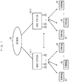
- FIG. 7 illustrates an example of a configuration of a wireless communication system that is assumed according to the present invention.
- base stations 10-1 and 10-2 that are connected to a network 30 are configured to use the same frequency channel and perform wireless communication with terminals 20 under the control of the base stations 10-1 and 10-2, respectively.
- each of the base stations 10-1 and 10-2 includes multiple antennas and is configured to perform MIMO communication with one or multiple terminals 20.
- the base stations 10-1 and 10-2 also include a function of adjusting a transmission or reception power of each antenna according to the terminal that is a destination.
- FIG. 8 illustrates an example of a configuration of a base station in the related art.
- the base station includes n (n is an integer of two or more) antennas 101 -1 to 101-n, power change units 102-1 to 102-n that change a transmission power and a reception power, transmission and reception units 103-1 to 103-n that perform transmission processing and reception processing of signals that are transmitted or received, respectively, in n antennas, a signal processing control unit 104 that performs conversion processing of a signal that is input or output into or from a network that is connected to the base station, and the signal that is transmitted or received in each of the n antennas, a power notification unit 105 that outputs a notification signal that includes an amount of power change by each of the power change units 102-1 to 102-n in accordance with a target terminal that is a destination or source of the signal that is transmitted or received, and a power control unit 106 that performs control of power changing by the power change units 102-1 to 102-n according to the notification signal. It is noted that the power notification unit 105 is present within the signal processing control unit 104.
- the power notification unit 105 extracts transmission power information that corresponds to each antenna for the target terminal that is set in advance, before performing the transmission processing, and notifies the power control unit 106 of the transmission power information that corresponds to each antenna. According to the notification signal from the power notification unit 105, the power control unit 106 performs control in such a manner that the transmission powers are changed by the power change units 102-1 to 102-n that correspond to the antennas 101-1 to 101-n, respectively. The same is true for the control of the reception power of a reception signal. Accordingly, because optimal transmission power control is performed on the target terminal, it is possible that a power that causes interference to any other wireless station is suppressed at the same time and that the number of opportunities for the entire wireless communication system to perform communication is increased. Thus, an improvement in throughput is expected.
- Non-Patent Document 2 As a technology that increases an effect of reducing the transmission power, progress has been made in a study on a distributed antenna technology that arranges multiple antennas that the base station has, in a distributed manner and thus shortens a distance between a base station antenna and a terminal antenna, thereby resulting in an increase in the reception power of each wireless station (Non-Patent Document 2).
- the reception power that increased is reduced, it is possible that the same communication quality as in the related art is secured. Because of this, a further reduction in the transmission power is also possible.
- WO 2016/175144 Aldiscloses a base station that combines digital precoding and analog beamforming.
- Transceiver antenna elements are divided into a plurality of antenna groups.
- An analog beamformer has a plurality of branches corresponding to the plurality of antenna groups. Each branch has a plurality of sub-branches, and each sub-branch is connected to one antenna element.
- self calibration it is possible to identify which antenna element of the plurality of antenna elements belonging to one antenna group sent a pilot signal received by an antenna element belonging to another antenna group. It is also possible to identify which antenna element among the plurality of antenna elements belonging to one antenna group received a pilot signal.
- the power control unit 106 performs control in such a manner that powers of signals that are transmitted or received in the antennas 101-1 to 101-n according to the target terminal are changed by the power change units 102-1 to 102-n, respectively, of the base station that is illustrated in FIG. 8 .
- the amount of power change that corresponds to each antenna is generated in the power notification unit 105 of the signal processing control unit 104 according to the target terminal and the generated amount of power change is notified to the power control unit 106.
- schemes for transfer of the notification signal that notifies the amount of power change that corresponds to each antenna the following two methods are considered.
- pieces of power change control information E1 to En for controlling the power change units 102-1 to 102-n, using n control lines, respectively, are notified in parallel.
- the pieces of power change control information E1 to En can be notified in a short time from the power notification unit 105 to the power control unit 106, and changing of the power of the signal that is transmitted or received in each antenna can be realized at a high speed.
- the n control lines are necessary, a problem of increasing a circuit scale and the cost occurs.
- the number of antennas of the base station increases greatly in the future, there is a need to solve this problem.
- the pieces of power change control information E1 to En for controlling the power change units 102-1 to 102-n, respectively, using one control line are notified in series.
- the number of control lines can be 1, but, depending on the number n of antennas, it takes time to notify all pieces of power change control information E1 to En. For example, there is a need to perform control to the precision of seconds or less to perform transmission power control on a per-wireless packet basis, and a problem of shortening the transfer time of the notification signal occurs.
- the distributed antenna is used for the purpose of further increasing a transmission power control effect, there is a need for a configuration in which the distributed antenna is selected on a per-wireless packet basis.
- there is a need for addition of an antenna switch unit and thus there is also a need for a control signal for controlling the antenna switch unit. Therefore, there is a need for not only an amount of power change that corresponds to each antenna but also a technology for efficiently notifying switch information for the antenna switch unit.
- the antenna switch unit and each change unit that changes the phase, the timing, the frequency, and the power for every antenna will differ in terms of a reaction time from the starting of switching and changing operations to the ending of switching and changing operations. Because of this, control is also necessary considering the reaction time of each unit.
- a proposition of the present invention is to provide a base station that is capable of performing at a high speed switching control and changing control of signals that are transmitted or received in multiple antennas, considering reaction times of each antenna switch unit and each change unit that changes the phase, the timing, the frequency, and the power of each signal, and a method of controlling the base station.
- a base station in a wireless communication system in which the base station and one or more terminals share the same frequency channel, the base station includes n antenna sets, , where n is an integer of two or more, each of the antenna sets contains multiple antennas; n number of antenna switch units selecting one antenna from each of the antenna sets; n number of signal change units each changing a combination of one or more of a phase, a timing, a frequency, and a power of each signal transmitted or received in n number of antennas being selected from the antenna sets, respectively, in the antenna switch units; a notification unit outputting a notification signal, in which control information on the antenna switch units and the signal change units according to a target terminal being a destination or source of the signals transmitted or received in the n number of antennas, are arranged according to a switch time of each of the antenna switch units and a change time of each of the signal change units (reaction time of each unit); and a control unit sequentially starting control of switching by each of the antenna switch units and control
- the notification unit is configured to arrange the control information on the each unit in the notification signal in order of decreasing amount of the reaction time of the each unit.
- the notification unit is configured to arrange the control information on the each unit in the notification signal so as to end the control of switching by each of the antenna switch units and the control of changing by each of the signal change units within a designated time.
- the notification unit is configured to reduce an amount of the control information on the each unit in the notification signal
- control unit, the antenna switch units, and the signal change units are configured to perform the control of switching and the control of changing, which correspond to the reduced amount of the control information.
- a change unit of at least one of the phase, the timing, the frequency, and the power of the signal change units is configured to connect multiple devices that differ in the reaction time; and the notification unit is configured to sequentially arrange the control information of the each unit in the notification signal starting from the control information on the devices having the longer reaction time.
- a control method of the base station includes a step of causing the base station to extract a target terminal for which a signal input from an external network is destined, and to determine control information based on a signal format according to the target terminal, an antenna to which each of the antenna switch units switches, and an amount of change in the phase, the timing, the frequency, and the power by the each unit of the signal change units; a step of causing the notification unit to generate a notification signal in which the control information on the each unit, which corresponds to the target terminal is arranged according to the reaction time of the each unit, and to transmit the generated notification signal to the control unit; and a step of causing the control unit to start the control of switching by the antenna switch units and the control of changing by the signal change units at the same time that the control information on the each unit in the notification signal arrives, in which a signal is transmitted and received after the controlling of the antenna switch units and the signal change units is finished.
- the notification unit arranges the control information on the each unit in the notification signal in order of decreasing amount of the reaction time of the each unit.
- the notification unit arranges the control information on the each unit in the notification signal so as to end the control of switching by each of the antenna switch units and the control of changing by each of the signal change units within a designated time.
- a notification signal in accordance with reaction times of each antenna switch unit and each signal change unit with respect to a phase, a timing, a frequency, and a power is configured and control is started at the same time that control information for each of the switching and changing arrives.
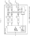
- FIG. 1 illustrates an example of a configuration of a base station according to the present invention.
- antenna sets 11-1 to 11-n of the base station are n sets of multiple antennas (n is an integer of two or more).
- Antenna switch units 12-1 to 12-n select an antenna from each of the antenna sets that is, select n antennas in total.
- Signal change units 13-1 to 13-n change phases, timings, frequencies, and powers of signals that are transmitted or received in the n antennas that are selected from the antenna sets, respectively.
- Transmission and reception units 14-1 to 14-n performs transmission processing and reception processing of signals that are transmitted or received in the n antennas, respectively.
- a signal processing control unit 15 performs the conversion processing of a signal that is input and output into and form a network that is connected to the base station and a signal that is transmitted or received in each antenna.
- a notification unit 16 outputs a notification signal that includes pieces of control information for the antenna switch units 12-1 to 12-n and the signal change units 13-1 to 13-n in accordance with a target terminal that is a destination or source of signals which are transmitted or received. According to the notification signal, a control unit 17 controls switch processing by the antenna switch units 12-1 to 12-n and change processing by the signal change units 13-1 to 13-n.
- each antenna in the antenna sets 11-1 to 11-n may be arranged in a distributed manner. Furthermore, a configuration that has directivity which differs among the antennas may be employed.
- One or all change units that make up the signal change units 13-1 to 13-n, which are responsible for a phase, a timing, a frequency, and a power are change targets according to the target terminal, and the control information of the notification signal is configured according to a combination of units that are the change targets among the units.
- the change units differ in terms of a reaction time from the starting of a change operation to the ending of the change operation, and each change unit may have a configuration in which multiple devices that differ in terms of the reaction time are connected in a multistage manner.
- FIG. 2 illustrates a procedure for signal transmission by the base station according to the present invention.
- the signal processing control unit 15 when a signal that is transmitted from an external network to the target terminal is input (S11), the signal processing control unit 15 extracts a target terminal for which the transmission signal is destined, determines a signal format in accordance with the target terminal, an antenna to which each of the antenna switch units 12-1 to 12-n switches, and an amount of change by each of the signal change units 13-1 to 13-n, and notifies the notification unit 16 of a result of the determination (S12).
- the signal processing control unit 15 retains these pieces of information in state of being associated with the target terminal, but a configuration may be employed in which an external control apparatus that is connected to a network notifies the notification unit 16 of the pieces of information.
- the signal format in accordance with the target terminal corresponds to a SU-MIMO signal that corresponds to one target terminal, an MU-MIMO signal that corresponds to multiple target terminals, a multicast signal, or the like, as each of the signals that are transmitted or received in n antennas to which the antenna switch units 12-1 to 12-n switch.
- the notification unit 16 generates the notification signal in which the pieces of information for control of switching and changing by each unit that corresponds to the target terminal are arranged according to a reaction time of each unit, and transmits the generated notification signal to the control unit 17 (S13).
- the control unit 1 7 starts the control of the switching by each of the antenna switch units 12-1 to 12-n and the control of the changing by each of the signal change units 13-1 to 13-n at the same time that the control information for each unit, of the notification signal arrives (S14). After the control for the antenna switch units 12-1 to 12-n and the signal change units 13-1 to 13-n is finished, a signal is transmitted (S15).
- steps that are to be performed after the signal processing control unit 15 and the notification unit 16 end signal transmission and then an amount of change for reception for each unit is determined as the control information are the same as those in the procedure for the signal transmission.
- a reception procedure is established in which the notification signal in which the pieces of control information for the units that correspond to the target terminal are arranged according to the reaction times of the units is generated and the generated notification signal is transmitted to the control unit 17, in which the control unit 17 starts the control of the switching by each of the antenna switch units 12-1 to 12-n and the control of the changing by each of the signal change units 13-1 to 13-n at the same time that the control information for each unit, of the notification signal arrives, and in which a signal waits to be received after completing such control.
- the notification unit 16 notifies the control unit 17 of an ending timing of the signal transmission, but the notification unit 16 or the control unit 17 considers the time that a signal takes to start from the transmission and reception units 14-1 to 14-n and pass through the antenna switch units 12-1 to 12-n.
- the point of the present invention is that the reaction time of each of the antenna switch units 12-1 to 12-n and the signal change units 13-1 to 13-n is considered and that the time to ending of the control for each unit, after which signal transmission or reception is possible, is shortened. This will be described in detail below.
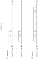
- FIG. 3 illustrates a first example of a configuration of the notification signal according to the present invention.
- pieces of antenna switch control information A1 to An for the antenna switch units 12-1 to 12-n, pieces of phase change control information B1 to Bn for the signal change units 13-1 to 13-n, pieces of timing change control information C1 to Cn, pieces of frequency change control information D1 to Dn, and pieces of power change control information E1 to En are arranged on a time axis.
- the notification signal that includes the control information that performs antenna switching and collectively changes a phase, a timing, a frequency, a power of the signal that is transmitted or received in each antenna, using one signal line from the notification unit 16 to the control unit 17 is described here, but the notification signal may be a notification signal that is made up of pieces of control information in accordance with a combination of two or more of the phase, the timing, the frequency, and the power, which are to be changed.
- the control unit 17 analyzes the notification signal into the control information for each of the antenna switch units 12-1 to 12-n and the signal change units 13-1 to 13-n, and sends resulting pieces of control information to the antenna switch units 12-1 to 12-n and the signal change units 13-1 to 13-n, respectively.
- a reaction time of the antenna switch units 12-1 to 12-n with respect to the control information is t1
- reaction times for the phase, the timing, the frequency, and the power, of each of the signal change units 13-1 to 13-n with respect to the control information are t2 to t5, respectively, and that, for example, a relationship among the reaction times is t1 ⁇ t5 ⁇ t2 ⁇ t3 ⁇ t4.
- a first feature of the present invention is that at the same time that the control information for each unit, of the notification signal is notified, the control unit 17 sequentially starts the control of the switching by each of the antenna switch units 12-1 to 12-n and the control of the changing by each of the signal change units 13-1 to 13-n. Accordingly, as long as the pieces of control information D1 to Dn for the frequency changing, the reaction time for which is longest do not occupy the last portion of the notification signal, the ending of all switching and changing is advanced and thus starting of the signal transmission or reception can be advanced.
- a second feature of the present invention is that the notification unit 16 generates the notification signal in which pieces of control information for the units are arranged in order of decreasing the reaction time. Accordingly, because the pieces of control information A1 to An for antenna switching, the reaction time of which is shortest occupies the last portion of the notification signal, the ending of all changing is reliably advanced and thus the starting of the signal transmission or reception can be advanced.
- the control of the switching by each of the antenna switch units 12-1 to 12-n and the control of the changing by each of the signal change units 13-1 to 13-n are started, as a starting operation, all together, after all n pieces of control information that correspond to all antennas arrive.
- an operation of controlling each unit may be started with respect to every control information for each antenna.
- the antenna switch units 12-1 to 12-n may start switching control all together with respect to the pieces of control information A1 to An, and the antenna switch unit 12-1 may start the switching control with respect to the control information A1 and may start the switching control sequentially thereafter.
- FIG. 4 is a second example of the configuration of the notification signal according to the present invention.
- (1) of FIG. 4 illustrates an example of (3) of FIG. 3 for comparison.
- the notification unit 16 In (2) of FIG. 4 , the notification unit 16 generates the notification signal in which the antenna switch units 12-1 to 12-n and the signal change units 13-1 to 13-n as a whole are arranged in such a manner that operations by the units are controlled to be ended within a designated time. That is, the notification unit 16 may select one from among combinations of notification signals with which the operations by the units are controlled to be ended within the designated time. If a condition that, with a combination of notification signals that is initially found, the operations be finished within the designated time is satisfied, this may be acceptable (First fit). Consequently, as illustrated in (1) of FIG.
- the pieces of control information D1 to Dn for the frequency changing, the reaction time for which is longest, are not limited to the first portion of the notification signal, or the pieces of control information A1 to An for the switch switching, the reaction time for which is shortest, are not limited to the last portion of the notification signal.
- FIG. 5 illustrates a third example of the configuration of the notification signal according to the present invention.
- (1) of FIG. 5 illustrates an example of (3) of FIG. 3 for comparison.
- a range of control for each of the antenna switch units 12-1 to 12-n and the signal change units 13-1 to 13-n, or resolution is limited, and thus the control information may be shortened, and the time taken for all switching and changing may be shortened.
- all pieces of control information for changing other than the pieces of antenna switch control information A1 to An are shortened, but one or several of the pieces of control information may be shortened.
- the control information may be shortened by a reduction in the number of antennas. Furthermore, even if the designated time that is designated in FIG. 4 is short, it is possible that this is dealt with by shortening each piece of control information.
- FIG. 6 illustrates a fourth example of the configuration of the notification signal according to the present invention.
- each of the signal change units 13-1 to 13-n has a configuration in which multiple devices that differ in terms of the reaction time are connected in a multistage manner, and an example of a configuration of the notification signal that corresponds to a frequency change unit which has a two-stage configuration is illustrated in FIG. 6 .
- control information for a first-stage device of the frequency change unit is defined as D1-1 to Dn-1, and control information for a second-state device as D1-2 to Dn-2, and reaction time t4-1 of the first-stage device is set to be longer than reaction time t4-2 of the second-stage device.
- arranging pieces of control information D1-1 to Dn - 1 for the first-stage device of the frequency change unit, of which the reaction time is long, into the head portion, and starting the frequency changing by the first stage device after the pieces of control information arrive can advance the time for ending all frequency changing, much more than arranging pieces of control information Di-1 and Di-2 for the first-stage device and the second-stage device in a set.
- inspection bits such as parity check bits or a frame check sequence
- the switching control or the changing control is started, but, if an error in the notification signal is detected with the inspection bits, the switching control or the changing control that is started in advance may be reset.
Landscapes
- Engineering & Computer Science (AREA)
- Computer Networks & Wireless Communication (AREA)
- Signal Processing (AREA)
- Power Engineering (AREA)
- Mobile Radio Communication Systems (AREA)
Claims (8)
- Basisstation (10) in einem drahtlosen Kommunikationssystem, in dem sich die Basisstation (10) und eines oder mehrere Endgeräte (20) denselben Frequenzkanal teilen, wobei die Basisstation (10) umfasst:n Antennensätze (11), wobei n eine ganze Zahl von zwei oder mehr ist, wobei jeder der Antennensätze (11) mehrere Antennen (101) enthält;n Anzahl von Antennenschalteinheiten (12), die eine Antenne aus jedem der Antennensätze (11) auswählen;n Anzahl von Signaländerungseinheiten (13), von denen jede eine Kombination aus einer oder mehreren einer Phase, einem Timing, einer Frequenz und einer Leistung jedes Signals, dass übertragen oder empfangen wird, in n Anzahl von Antennen, die aus den jeweiligen Antennensätzen (11) ausgewählt werden, in den Antennenschalteinheiten (12) ändert;eine Benachrichtigungseinheit (16), die ein Benachrichtigungssignal ausgibt, in dem Steuerinformationen über die Antennenschalteinheiten (12) und die Signaländerungseinheiten (13) gemäß einem Zielendgerät, dass ein Ziel oder eine Quelle der übertragenen oder empfangenen Signale ist, in n Anzahl von Antennen, die gemäß einer Schaltzeit jeder der Antennenschalteinheiten (12) und einer Schaltzeit jeder der Signaländerungseinheiten (13) angeordnet ist, die im Folgenden als "Reaktionszeit jeder Einheit" bezeichnet wird; undeine Steuereinheit (17), die sequentiell die Steuerung des Schaltens durch jede der Antennenschalteinheiten (12) und die Steuerung des Änderns durch jede der Signaländerungseinheiten (13) startet, in der Reihenfolge, in der die Steuerinformationen über jede Einheit in dem Benachrichtigungssignal gemeldet werden.
- Basisstation (10) nach Anspruch 1, wobei
die Benachrichtigungseinheit (16) konfiguriert ist, um die Steuerinformationen über jede Einheit in dem Benachrichtigungssignal in der Reihenfolge des abnehmenden Betrags der Reaktionszeit jeder Einheit anzuordnen. - Basisstation (10) nach Anspruch 1, wobei
die Benachrichtigungseinheit (16) konfiguriert ist, um die Steuerinformationen über jede Einheit in dem Benachrichtigungssignal anzuordnen, um die Steuerung des Schaltens durch jede der Antennenschalteinheiten (12) und die Steuerung des Änderns durch jede der Signaländerungseinheiten (13) innerhalb einer angegebenen Zeit zu beenden. - Basisstation (10) nach Anspruch 1, wobei:die Benachrichtigungseinheit (16) konfiguriert ist, um einen Betrag der Steuerinformationen über jede Einheit in dem Benachrichtigungssignal zu reduzieren; unddie Steuereinheit (17), die Antennenschalteinheiten (12) und die Signaländerungseinheiten (13) konfiguriert sind, um die Schaltsteuerung und die Änderungssteuerung durchzuführen, die dem reduzierten Betrag der Steuerinformationen entsprechen.
- Basisstation (10) nach Anspruch 1, wobei:eine Änderungseinheit von zumindest einem von der Phase, dem Timing, der Frequenz und/oder der Leistung der Signaländerungseinheiten (13) konfiguriert ist, um mehrere Vorrichtungen zu verbinden, die sich in der Reaktionszeit unterscheiden; unddie Benachrichtigungseinheit (16) konfiguriert ist, um die Steuerinformationen über jede Einheit in dem Benachrichtigungssignal sequentiell ausgehend von den Steuerinformationen über die Vorrichtungen mit einer längeren Reaktionszeit anzuordnen.
- Steuerverfahren der Basisstation (10) nach Anspruch 1, wobei das Verfahren umfasst:einen Schritt, der die Basisstation (10) veranlasst, ein Zielendgerät zu extrahieren, für das eine Signaleingabe von einem externen Netzwerk bestimmt ist, und um Steuerinformationen basierend auf einem Signalformat gemäß dem Zielendgerät, einer Antenne, zu der jede der Antennenschalteinheiten (12) schaltet, und einen Änderungsbetrag der Phase, des Timings, der Frequenz und der Leistung durch jede Einheit der Signaländerungseinheiten (13) zu bestimmen;einen Schritt, der die Benachrichtigungseinheit (16) veranlasst, ein Benachrichtigungssignal zu generieren, in dem die Steuerinformationen über jede Einheit, die dem Zielendgerät entspricht, gemäß der Reaktionszeit jeder Einheit anzuordnen, und das generierte Benachrichtigungssignal an die Steuereinheit (17) zu übertragen; undeinen Schritt, der die Steuereinheit (17) veranlasst, die Steuerung des Schaltens durch die Antennenschalteinheiten (12) und die Steuerung des Änderns durch jede der die Signaländerungseinheiten (13) zu starten, während gleichzeitig die Steuerinformationen über jede Einheit in dem Benachrichtigungssignal ankommen, wobeiein Signal übertragen und empfangen wird, nachdem die Steuerung der Antennenschalteinheiten (12) und der Signaländerungseinheiten (13) abgeschlossen ist.
- Steuerverfahren der Basisstation (10) nach Anspruch 6, wobei
die Benachrichtigungseinheit (16) die Steuerinformationen über jede Einheit in dem Benachrichtigungssignal in der Reihenfolge des abnehmenden Betrags der Reaktionszeit jeder Einheit anordnet. - Steuerverfahren der Basisstation (10) nach Anspruch 6, wobei
die Benachrichtigungseinheit (16) die Steuerinformationen über jede Einheit in dem Benachrichtigungssignal anordnet, um die Steuerung des Schaltens durch jede der Antennenschalteinheiten (12) und die Steuerung des Änderns durch jede der Signaländerungseinheiten (13) innerhalb einer angegebenen Zeit zu beenden.
Applications Claiming Priority (2)
| Application Number | Priority Date | Filing Date | Title |
|---|---|---|---|
| JP2017013222 | 2017-01-27 | ||
| PCT/JP2018/002295 WO2018139539A1 (ja) | 2017-01-27 | 2018-01-25 | 無線基地局およびその制御方法 |
Publications (3)
| Publication Number | Publication Date |
|---|---|
| EP3576313A1 EP3576313A1 (de) | 2019-12-04 |
| EP3576313A4 EP3576313A4 (de) | 2020-10-28 |
| EP3576313B1 true EP3576313B1 (de) | 2021-09-15 |
Family
ID=62978391
Family Applications (1)
| Application Number | Title | Priority Date | Filing Date |
|---|---|---|---|
| EP18744761.0A Active EP3576313B1 (de) | 2017-01-27 | 2018-01-25 | Basisstation und zugehöriges steuerungsverfahren |
Country Status (7)
| Country | Link |
|---|---|
| US (1) | US11005545B2 (de) |
| EP (1) | EP3576313B1 (de) |
| JP (1) | JP6742446B2 (de) |
| KR (1) | KR102236797B1 (de) |
| CN (1) | CN110268639B (de) |
| TW (1) | TWI646790B (de) |
| WO (1) | WO2018139539A1 (de) |
Families Citing this family (3)
| Publication number | Priority date | Publication date | Assignee | Title |
|---|---|---|---|---|
| US10334085B2 (en) * | 2015-01-29 | 2019-06-25 | Splunk Inc. | Facilitating custom content extraction from network packets |
| CN109474964A (zh) * | 2018-11-21 | 2019-03-15 | Tcl移动通信科技(宁波)有限公司 | 移动终端lte频段选择处理方法、移动终端及存储介质 |
| JP2023142065A (ja) * | 2022-03-24 | 2023-10-05 | 株式会社国際電気通信基礎技術研究所 | 推定装置、それを備える無線通信システムおよびコンピュータに実行させるためのプログラム |
Family Cites Families (20)
| Publication number | Priority date | Publication date | Assignee | Title |
|---|---|---|---|---|
| WO2002025859A1 (en) * | 2000-09-12 | 2002-03-28 | Kvaser Consultant Ab | An arrangement with a number of units that can communicate with each other via a wireless connection system and a method for use with such a system |
| CN1225849C (zh) * | 2003-07-18 | 2005-11-02 | 大唐移动通信设备有限公司 | 一种对无线信号进行双向同步转发的方法及装置 |
| JP2005341531A (ja) | 2004-04-27 | 2005-12-08 | Matsushita Electric Ind Co Ltd | 無線通信システム及び無線局 |
| US7826807B2 (en) * | 2005-03-09 | 2010-11-02 | Qualcomm Incorporated | Methods and apparatus for antenna control in a wireless terminal |
| JP2007295253A (ja) * | 2006-04-25 | 2007-11-08 | Fujitsu Ten Ltd | 受信制御装置並びに切替制御方法 |
| JP5069298B2 (ja) * | 2006-08-07 | 2012-11-07 | クゥアルコム・インコーポレイテッド | 非同期無線通信に関するメッセージ交換方式 |
| US8107915B2 (en) * | 2008-04-28 | 2012-01-31 | Delphi Technologies, Inc. | Receiver system and method for receiving signals |
| US20100304773A1 (en) * | 2009-05-27 | 2010-12-02 | Ramprashad Sean A | Method for selective antenna activation and per antenna or antenna group power assignments in cooperative signaling wireless mimo systems |
| CN102340860B (zh) * | 2010-07-27 | 2014-04-02 | 杭州华三通信技术有限公司 | 一种智能天线系统的功率控制方法和装置 |
| EP2624478B1 (de) * | 2010-09-30 | 2022-07-20 | Panasonic Holdings Corporation | Funkkommunikationsgerät |
| JP5289486B2 (ja) * | 2011-03-08 | 2013-09-11 | 株式会社東芝 | 無線基地局装置、無線部制御装置及び無線通信方法 |
| US20120274154A1 (en) * | 2011-04-27 | 2012-11-01 | Research In Motion Limited | Methods and apparatuses for wireless power transfer |
| JP2015008363A (ja) * | 2013-06-24 | 2015-01-15 | 株式会社東芝 | 分散アンテナシステム、管理制御装置、管理制御装置の制御方法及び制御プログラム |
| US10396885B2 (en) * | 2013-09-11 | 2019-08-27 | Intel Corporation | Dynamic partitioning of modular phased array architectures for multiple uses |
| JPWO2015146340A1 (ja) * | 2014-03-26 | 2017-04-13 | ソニー株式会社 | 装置及び方法 |
| WO2016175144A1 (ja) | 2015-04-30 | 2016-11-03 | 株式会社Nttドコモ | 無線基地局 |
| WO2016174774A1 (ja) * | 2015-04-30 | 2016-11-03 | 三菱電機株式会社 | 送信局、制御局、受信局、データ伝送システムおよびデータ伝送方法 |
| US10686487B2 (en) * | 2015-06-23 | 2020-06-16 | Eridan Communications, Inc. | Universal transmit/receive module for radar and communications |
| US10863424B2 (en) * | 2016-04-27 | 2020-12-08 | Telefonaktiebolaget Lm Ericsson (Publ) | Technique for transmitting discovery-related signals from a transmission point to a user equipment |
| US20180198204A1 (en) * | 2016-12-13 | 2018-07-12 | Skyworks Solutions, Inc. | Apparatus and methods for dynamic management of antenna arrays |
-
2018
- 2018-01-25 WO PCT/JP2018/002295 patent/WO2018139539A1/ja not_active Ceased
- 2018-01-25 KR KR1020197021945A patent/KR102236797B1/ko active Active
- 2018-01-25 JP JP2018564629A patent/JP6742446B2/ja active Active
- 2018-01-25 EP EP18744761.0A patent/EP3576313B1/de active Active
- 2018-01-25 US US16/480,122 patent/US11005545B2/en active Active
- 2018-01-25 CN CN201880008662.XA patent/CN110268639B/zh active Active
- 2018-01-26 TW TW107102906A patent/TWI646790B/zh active
Also Published As
| Publication number | Publication date |
|---|---|
| EP3576313A4 (de) | 2020-10-28 |
| JPWO2018139539A1 (ja) | 2019-12-19 |
| CN110268639B (zh) | 2022-04-01 |
| WO2018139539A1 (ja) | 2018-08-02 |
| US20190386724A1 (en) | 2019-12-19 |
| CN110268639A (zh) | 2019-09-20 |
| TWI646790B (zh) | 2019-01-01 |
| EP3576313A1 (de) | 2019-12-04 |
| US11005545B2 (en) | 2021-05-11 |
| TW201832490A (zh) | 2018-09-01 |
| KR102236797B1 (ko) | 2021-04-06 |
| JP6742446B2 (ja) | 2020-08-19 |
| KR20190095480A (ko) | 2019-08-14 |
Similar Documents
| Publication | Publication Date | Title |
|---|---|---|
| US11044720B2 (en) | Beam sweep configuration | |
| CN107078771B (zh) | 无线通信系统中多用户波束成形的方法和装置 | |
| CN109905153B (zh) | 自适应mu-mimo波束成形 | |
| US10680685B2 (en) | Method and node in a wireless communication network | |
| US11075677B2 (en) | Method and device for sending beam refinement protocol packet | |
| EP2661787B1 (de) | Gruppenantenne zur unterstützung von mehrstrahlarchitekturen | |
| US12388509B2 (en) | Method for selecting cyclic shift diversity sequence, and related apparatus | |
| US11528628B2 (en) | Radio base station using distributed antenna and scheduling method | |
| EP3576313B1 (de) | Basisstation und zugehöriges steuerungsverfahren | |
| JP6509758B2 (ja) | 指向性切替アンテナを用いた無線基地局およびアンテナ指向性切替方法 | |
| KR102329454B1 (ko) | 무선망 환경에서의 간섭정렬 및 다중안테나 신호처리 방법 및 장치 | |
| US11962527B2 (en) | Communication method and apparatus | |
| US10827436B2 (en) | Base station and method of controlling transmission/reception power |
Legal Events
| Date | Code | Title | Description |
|---|---|---|---|
| STAA | Information on the status of an ep patent application or granted ep patent |
Free format text: STATUS: THE INTERNATIONAL PUBLICATION HAS BEEN MADE |
|
| PUAI | Public reference made under article 153(3) epc to a published international application that has entered the european phase |
Free format text: ORIGINAL CODE: 0009012 |
|
| STAA | Information on the status of an ep patent application or granted ep patent |
Free format text: STATUS: REQUEST FOR EXAMINATION WAS MADE |
|
| 17P | Request for examination filed |
Effective date: 20190724 |
|
| AK | Designated contracting states |
Kind code of ref document: A1 Designated state(s): AL AT BE BG CH CY CZ DE DK EE ES FI FR GB GR HR HU IE IS IT LI LT LU LV MC MK MT NL NO PL PT RO RS SE SI SK SM TR |
|
| AX | Request for extension of the european patent |
Extension state: BA ME |
|
| DAV | Request for validation of the european patent (deleted) | ||
| DAX | Request for extension of the european patent (deleted) | ||
| A4 | Supplementary search report drawn up and despatched |
Effective date: 20200925 |
|
| RIC1 | Information provided on ipc code assigned before grant |
Ipc: H04W 16/28 20090101ALI20200921BHEP Ipc: H04W 52/42 20090101ALI20200921BHEP Ipc: H04W 88/08 20090101ALI20200921BHEP Ipc: H04W 84/12 20090101ALI20200921BHEP Ipc: H01Q 3/26 20060101ALI20200921BHEP Ipc: H04B 7/06 20060101AFI20200921BHEP Ipc: H04B 7/0413 20170101ALN20200921BHEP |
|
| STAA | Information on the status of an ep patent application or granted ep patent |
Free format text: STATUS: EXAMINATION IS IN PROGRESS |
|
| 17Q | First examination report despatched |
Effective date: 20201117 |
|
| GRAP | Despatch of communication of intention to grant a patent |
Free format text: ORIGINAL CODE: EPIDOSNIGR1 |
|
| STAA | Information on the status of an ep patent application or granted ep patent |
Free format text: STATUS: GRANT OF PATENT IS INTENDED |
|
| RIC1 | Information provided on ipc code assigned before grant |
Ipc: H04B 7/0413 20170101ALN20210428BHEP Ipc: H01Q 3/26 20060101ALI20210428BHEP Ipc: H04W 88/08 20090101ALI20210428BHEP Ipc: H04W 84/12 20090101ALI20210428BHEP Ipc: H04W 16/28 20090101ALI20210428BHEP Ipc: H04W 52/42 20090101ALI20210428BHEP Ipc: H04B 7/06 20060101AFI20210428BHEP |
|
| INTG | Intention to grant announced |
Effective date: 20210527 |
|
| GRAS | Grant fee paid |
Free format text: ORIGINAL CODE: EPIDOSNIGR3 |
|
| GRAA | (expected) grant |
Free format text: ORIGINAL CODE: 0009210 |
|
| STAA | Information on the status of an ep patent application or granted ep patent |
Free format text: STATUS: THE PATENT HAS BEEN GRANTED |
|
| AK | Designated contracting states |
Kind code of ref document: B1 Designated state(s): AL AT BE BG CH CY CZ DE DK EE ES FI FR GB GR HR HU IE IS IT LI LT LU LV MC MK MT NL NO PL PT RO RS SE SI SK SM TR |
|
| REG | Reference to a national code |
Ref country code: CH Ref legal event code: EP |
|
| REG | Reference to a national code |
Ref country code: DE Ref legal event code: R096 Ref document number: 602018023626 Country of ref document: DE |
|
| REG | Reference to a national code |
Ref country code: IE Ref legal event code: FG4D |
|
| REG | Reference to a national code |
Ref country code: AT Ref legal event code: REF Ref document number: 1431345 Country of ref document: AT Kind code of ref document: T Effective date: 20211015 |
|
| REG | Reference to a national code |
Ref country code: LT Ref legal event code: MG9D |
|
| REG | Reference to a national code |
Ref country code: NL Ref legal event code: MP Effective date: 20210915 |
|
| PG25 | Lapsed in a contracting state [announced via postgrant information from national office to epo] |
Ref country code: NO Free format text: LAPSE BECAUSE OF FAILURE TO SUBMIT A TRANSLATION OF THE DESCRIPTION OR TO PAY THE FEE WITHIN THE PRESCRIBED TIME-LIMIT Effective date: 20211215 Ref country code: LT Free format text: LAPSE BECAUSE OF FAILURE TO SUBMIT A TRANSLATION OF THE DESCRIPTION OR TO PAY THE FEE WITHIN THE PRESCRIBED TIME-LIMIT Effective date: 20210915 Ref country code: BG Free format text: LAPSE BECAUSE OF FAILURE TO SUBMIT A TRANSLATION OF THE DESCRIPTION OR TO PAY THE FEE WITHIN THE PRESCRIBED TIME-LIMIT Effective date: 20211215 Ref country code: SE Free format text: LAPSE BECAUSE OF FAILURE TO SUBMIT A TRANSLATION OF THE DESCRIPTION OR TO PAY THE FEE WITHIN THE PRESCRIBED TIME-LIMIT Effective date: 20210915 Ref country code: RS Free format text: LAPSE BECAUSE OF FAILURE TO SUBMIT A TRANSLATION OF THE DESCRIPTION OR TO PAY THE FEE WITHIN THE PRESCRIBED TIME-LIMIT Effective date: 20210915 Ref country code: HR Free format text: LAPSE BECAUSE OF FAILURE TO SUBMIT A TRANSLATION OF THE DESCRIPTION OR TO PAY THE FEE WITHIN THE PRESCRIBED TIME-LIMIT Effective date: 20210915 Ref country code: FI Free format text: LAPSE BECAUSE OF FAILURE TO SUBMIT A TRANSLATION OF THE DESCRIPTION OR TO PAY THE FEE WITHIN THE PRESCRIBED TIME-LIMIT Effective date: 20210915 |
|
| REG | Reference to a national code |
Ref country code: AT Ref legal event code: MK05 Ref document number: 1431345 Country of ref document: AT Kind code of ref document: T Effective date: 20210915 |
|
| PG25 | Lapsed in a contracting state [announced via postgrant information from national office to epo] |
Ref country code: LV Free format text: LAPSE BECAUSE OF FAILURE TO SUBMIT A TRANSLATION OF THE DESCRIPTION OR TO PAY THE FEE WITHIN THE PRESCRIBED TIME-LIMIT Effective date: 20210915 Ref country code: GR Free format text: LAPSE BECAUSE OF FAILURE TO SUBMIT A TRANSLATION OF THE DESCRIPTION OR TO PAY THE FEE WITHIN THE PRESCRIBED TIME-LIMIT Effective date: 20211216 |
|
| PG25 | Lapsed in a contracting state [announced via postgrant information from national office to epo] |
Ref country code: AT Free format text: LAPSE BECAUSE OF FAILURE TO SUBMIT A TRANSLATION OF THE DESCRIPTION OR TO PAY THE FEE WITHIN THE PRESCRIBED TIME-LIMIT Effective date: 20210915 |
|
| PG25 | Lapsed in a contracting state [announced via postgrant information from national office to epo] |
Ref country code: IS Free format text: LAPSE BECAUSE OF FAILURE TO SUBMIT A TRANSLATION OF THE DESCRIPTION OR TO PAY THE FEE WITHIN THE PRESCRIBED TIME-LIMIT Effective date: 20220115 Ref country code: SM Free format text: LAPSE BECAUSE OF FAILURE TO SUBMIT A TRANSLATION OF THE DESCRIPTION OR TO PAY THE FEE WITHIN THE PRESCRIBED TIME-LIMIT Effective date: 20210915 Ref country code: SK Free format text: LAPSE BECAUSE OF FAILURE TO SUBMIT A TRANSLATION OF THE DESCRIPTION OR TO PAY THE FEE WITHIN THE PRESCRIBED TIME-LIMIT Effective date: 20210915 Ref country code: RO Free format text: LAPSE BECAUSE OF FAILURE TO SUBMIT A TRANSLATION OF THE DESCRIPTION OR TO PAY THE FEE WITHIN THE PRESCRIBED TIME-LIMIT Effective date: 20210915 Ref country code: PT Free format text: LAPSE BECAUSE OF FAILURE TO SUBMIT A TRANSLATION OF THE DESCRIPTION OR TO PAY THE FEE WITHIN THE PRESCRIBED TIME-LIMIT Effective date: 20220117 Ref country code: PL Free format text: LAPSE BECAUSE OF FAILURE TO SUBMIT A TRANSLATION OF THE DESCRIPTION OR TO PAY THE FEE WITHIN THE PRESCRIBED TIME-LIMIT Effective date: 20210915 Ref country code: NL Free format text: LAPSE BECAUSE OF FAILURE TO SUBMIT A TRANSLATION OF THE DESCRIPTION OR TO PAY THE FEE WITHIN THE PRESCRIBED TIME-LIMIT Effective date: 20210915 Ref country code: ES Free format text: LAPSE BECAUSE OF FAILURE TO SUBMIT A TRANSLATION OF THE DESCRIPTION OR TO PAY THE FEE WITHIN THE PRESCRIBED TIME-LIMIT Effective date: 20210915 Ref country code: EE Free format text: LAPSE BECAUSE OF FAILURE TO SUBMIT A TRANSLATION OF THE DESCRIPTION OR TO PAY THE FEE WITHIN THE PRESCRIBED TIME-LIMIT Effective date: 20210915 Ref country code: CZ Free format text: LAPSE BECAUSE OF FAILURE TO SUBMIT A TRANSLATION OF THE DESCRIPTION OR TO PAY THE FEE WITHIN THE PRESCRIBED TIME-LIMIT Effective date: 20210915 Ref country code: AL Free format text: LAPSE BECAUSE OF FAILURE TO SUBMIT A TRANSLATION OF THE DESCRIPTION OR TO PAY THE FEE WITHIN THE PRESCRIBED TIME-LIMIT Effective date: 20210915 |
|
| REG | Reference to a national code |
Ref country code: DE Ref legal event code: R097 Ref document number: 602018023626 Country of ref document: DE |
|
| PLBE | No opposition filed within time limit |
Free format text: ORIGINAL CODE: 0009261 |
|
| STAA | Information on the status of an ep patent application or granted ep patent |
Free format text: STATUS: NO OPPOSITION FILED WITHIN TIME LIMIT |
|
| PG25 | Lapsed in a contracting state [announced via postgrant information from national office to epo] |
Ref country code: DK Free format text: LAPSE BECAUSE OF FAILURE TO SUBMIT A TRANSLATION OF THE DESCRIPTION OR TO PAY THE FEE WITHIN THE PRESCRIBED TIME-LIMIT Effective date: 20210915 |
|
| 26N | No opposition filed |
Effective date: 20220616 |
|
| PG25 | Lapsed in a contracting state [announced via postgrant information from national office to epo] |
Ref country code: SI Free format text: LAPSE BECAUSE OF FAILURE TO SUBMIT A TRANSLATION OF THE DESCRIPTION OR TO PAY THE FEE WITHIN THE PRESCRIBED TIME-LIMIT Effective date: 20210915 Ref country code: MC Free format text: LAPSE BECAUSE OF FAILURE TO SUBMIT A TRANSLATION OF THE DESCRIPTION OR TO PAY THE FEE WITHIN THE PRESCRIBED TIME-LIMIT Effective date: 20210915 |
|
| REG | Reference to a national code |
Ref country code: CH Ref legal event code: PL |
|
| REG | Reference to a national code |
Ref country code: BE Ref legal event code: MM Effective date: 20220131 |
|
| PG25 | Lapsed in a contracting state [announced via postgrant information from national office to epo] |
Ref country code: LU Free format text: LAPSE BECAUSE OF NON-PAYMENT OF DUE FEES Effective date: 20220125 |
|
| PG25 | Lapsed in a contracting state [announced via postgrant information from national office to epo] |
Ref country code: BE Free format text: LAPSE BECAUSE OF NON-PAYMENT OF DUE FEES Effective date: 20220131 |
|
| PG25 | Lapsed in a contracting state [announced via postgrant information from national office to epo] |
Ref country code: LI Free format text: LAPSE BECAUSE OF NON-PAYMENT OF DUE FEES Effective date: 20220131 Ref country code: CH Free format text: LAPSE BECAUSE OF NON-PAYMENT OF DUE FEES Effective date: 20220131 |
|
| PG25 | Lapsed in a contracting state [announced via postgrant information from national office to epo] |
Ref country code: IT Free format text: LAPSE BECAUSE OF FAILURE TO SUBMIT A TRANSLATION OF THE DESCRIPTION OR TO PAY THE FEE WITHIN THE PRESCRIBED TIME-LIMIT Effective date: 20210915 Ref country code: IE Free format text: LAPSE BECAUSE OF NON-PAYMENT OF DUE FEES Effective date: 20220125 |
|
| PG25 | Lapsed in a contracting state [announced via postgrant information from national office to epo] |
Ref country code: MK Free format text: LAPSE BECAUSE OF FAILURE TO SUBMIT A TRANSLATION OF THE DESCRIPTION OR TO PAY THE FEE WITHIN THE PRESCRIBED TIME-LIMIT Effective date: 20210915 Ref country code: CY Free format text: LAPSE BECAUSE OF FAILURE TO SUBMIT A TRANSLATION OF THE DESCRIPTION OR TO PAY THE FEE WITHIN THE PRESCRIBED TIME-LIMIT Effective date: 20210915 |
|
| PG25 | Lapsed in a contracting state [announced via postgrant information from national office to epo] |
Ref country code: HU Free format text: LAPSE BECAUSE OF FAILURE TO SUBMIT A TRANSLATION OF THE DESCRIPTION OR TO PAY THE FEE WITHIN THE PRESCRIBED TIME-LIMIT; INVALID AB INITIO Effective date: 20180125 |
|
| PG25 | Lapsed in a contracting state [announced via postgrant information from national office to epo] |
Ref country code: MT Free format text: LAPSE BECAUSE OF FAILURE TO SUBMIT A TRANSLATION OF THE DESCRIPTION OR TO PAY THE FEE WITHIN THE PRESCRIBED TIME-LIMIT Effective date: 20210915 |
|
| PGFP | Annual fee paid to national office [announced via postgrant information from national office to epo] |
Ref country code: DE Payment date: 20250121 Year of fee payment: 8 |
|
| PGFP | Annual fee paid to national office [announced via postgrant information from national office to epo] |
Ref country code: FR Payment date: 20250127 Year of fee payment: 8 |
|
| PGFP | Annual fee paid to national office [announced via postgrant information from national office to epo] |
Ref country code: GB Payment date: 20250128 Year of fee payment: 8 |
|
| PG25 | Lapsed in a contracting state [announced via postgrant information from national office to epo] |
Ref country code: TR Free format text: LAPSE BECAUSE OF FAILURE TO SUBMIT A TRANSLATION OF THE DESCRIPTION OR TO PAY THE FEE WITHIN THE PRESCRIBED TIME-LIMIT Effective date: 20210915 |