EP3576025A1 - Flux control of qubit under resonant excitation - Google Patents
Flux control of qubit under resonant excitation Download PDFInfo
- Publication number
- EP3576025A1 EP3576025A1 EP19187630.9A EP19187630A EP3576025A1 EP 3576025 A1 EP3576025 A1 EP 3576025A1 EP 19187630 A EP19187630 A EP 19187630A EP 3576025 A1 EP3576025 A1 EP 3576025A1
- Authority
- EP
- European Patent Office
- Prior art keywords
- qubit
- flux
- frequency
- rabi oscillation
- energy spectrum
- Prior art date
- Legal status (The legal status is an assumption and is not a legal conclusion. Google has not performed a legal analysis and makes no representation as to the accuracy of the status listed.)
- Granted
Links
Images

Classifications
-
- G—PHYSICS
- G06—COMPUTING OR CALCULATING; COUNTING
- G06N—COMPUTING ARRANGEMENTS BASED ON SPECIFIC COMPUTATIONAL MODELS
- G06N10/00—Quantum computing, i.e. information processing based on quantum-mechanical phenomena
- G06N10/40—Physical realisations or architectures of quantum processors or components for manipulating qubits, e.g. qubit coupling or qubit control
-
- H—ELECTRICITY
- H04—ELECTRIC COMMUNICATION TECHNIQUE
- H04B—TRANSMISSION
- H04B10/00—Transmission systems employing electromagnetic waves other than radio-waves, e.g. infrared, visible or ultraviolet light, or employing corpuscular radiation, e.g. quantum communication
- H04B10/70—Photonic quantum communication
-
- H—ELECTRICITY
- H04—ELECTRIC COMMUNICATION TECHNIQUE
- H04B—TRANSMISSION
- H04B10/00—Transmission systems employing electromagnetic waves other than radio-waves, e.g. infrared, visible or ultraviolet light, or employing corpuscular radiation, e.g. quantum communication
- H04B10/90—Non-optical transmission systems, e.g. transmission systems employing non-photonic corpuscular radiation
-
- B—PERFORMING OPERATIONS; TRANSPORTING
- B82—NANOTECHNOLOGY
- B82Y—SPECIFIC USES OR APPLICATIONS OF NANOSTRUCTURES; MEASUREMENT OR ANALYSIS OF NANOSTRUCTURES; MANUFACTURE OR TREATMENT OF NANOSTRUCTURES
- B82Y10/00—Nanotechnology for information processing, storage or transmission, e.g. quantum computing or single electron logic
Definitions
- the invention relates generally to quantum computing, and more specifically, to flux control of qubit under resonant excitation.
- Quantum information processing requires large numbers and high densities of qubits to implement quantum algorithms, and even greater amounts of classical control and readout hardware to operate the qubits.
- quantum algorithms and even greater amounts of classical control and readout hardware to operate the qubits.
- cryogenic hardware capable of the control and readout of qubits.
- the qubit with the current record for coherence times and process fidelities, the transmon, is currently controlled with bulky room temperature microwave equipment.
- a system for flux control of a qubit.
- a quantum system includes a microwave transmitter configured to provide a continuous microwave tone, and a qubit configured such that a portion of an energy spectrum of the qubit is responsive to an applied flux.
- the qubit also has an inductive element responsive to the continuous microwave tone to produce a Rabi oscillation within the qubit.
- a flux source is configured to apply a flux to the qubit.
- a method for performing an X rotation of a qubit.
- the qubit is configured such that the qubit is responsive to the continuous microwave tone to produce a Rabi oscillation within the qubit and a portion of an energy spectrum of the qubit is responsive to an applied flux.
- a continuous microwave tone is provided to the qubit.
- a flux pulse is provided to the qubit as to tune the energy spectrum of the qubit to a frequency of the Rabi oscillation for a predetermined time. The flux pulse is adjusted to detune the energy spectrum of the qubit from the frequency of the Rabi oscillation after the predetermined time.
- a method for performing a Y rotation of a qubit.
- the qubit is configured such that the qubit is responsive to the continuous microwave tone to produce a Rabi oscillation within the qubit and a portion of an energy spectrum of the qubit is responsive to an applied flux.
- a continuous microwave tone is provided to the qubit.
- a flux pulse is provided to the qubit as to detune the energy spectrum of the qubit from a frequency of the Rabi oscillation by a first predetermined amount for a predetermined time.
- the flux pulse to the qubit is adjusted as to detune the energy spectrum of the qubit from a frequency of the Rabi oscillation by a second predetermined amount for the predetermined time.
- the second predetermined amount is the additive inverse of the first predetermined amount.
- phase and amplitude modulated burst of microwaves have been used to control transmon qubits. These systems require two high sample rate arbitrary waveform channels and a series of bulky room temperature microwave components per qubit.
- the proposed system and methods allows for the control of a superconducting qubit using a single waveform channel capable of making a square wave pulse, rather than the traditional shaped microwave burst.
- This control method is compatible with Single Flux Quantum (SFQ) systems, which can generate the control signals on chip at cryogenic temperatures, improving the scalability of the qubit control hardware.
- SFQ Single Flux Quantum
- the system can eliminate the need for room temperature signal generation or sophisticated microwave techniques through the use of continuous resonant microwave excitations and quasi-static flux pulses to achieve orthogonal, universal control of a single qubit precise control of a superconducting qubit with a Single Flux Quantum (SFQ) style flux.
- SFQ Single Flux Quantum
- FIG. 1 illustrates a quantum system 10 for controlling a state of at least one qubit 12.
- the qubit 12 is configured such that a portion of an energy spectrum of the qubit is responsive to an applied flux. Specifically, at least a portion of the energy spectrum of the qubit must be linearly dependent on an applied flux. Examples of such qubits include flux qubits and transmon qubits.
- the qubit 12 includes an inductive element (not shown) responsive to a continuous microwave tone to produce a coherent Rabi oscillation within the qubit.
- the system 10 further includes a microwave transmitter 14 configured to provide a continuous microwave tone to the qubit. When the microwave transmitter 14 is active, a Rabi oscillation having a known frequency is induced within the qubit. It will be appreciated that the microwave transmitter 14 can be located outside of a cryogenic portion of the system 10, and is capable of broadcasting to multiple qubits.
- the illustrated system 10 allows the qubit 12 to be controlled using flux pulses instead of shaped microwave bursts.
- the system 10 includes a flux source 16 controlled by a system control 18 as to selectively apply flux to the qubit, such that a qubit resonance frequency associated with the energy spectrum of the qubit can be selectively tuned to a frequency of the Rabi oscillation.
- the flux source 16 and the system control 18 are implemented as a single flux quantum (SFQ) logic circuit.
- the flux source 16 tunes a transition energy, and thus an accompanying characteristic frequency, between a ground state of the qubit 12 and a first excited state.
- this transition can be tuned relative to the Rabi frequency, as to rotate the state of qubit along one of two orthogonal axes.
- the flux source 16 can be located within the cryogenic portion of the system with the qubit, with the system control 18 located outside of this region.
- the system control 18 can be implemented as software executed by a general-purpose processor, dedicated hardware, or a mix of software and dedicated hardware.
- the qubit resonance frequency is controlled by the application of a flux to a junction loop of the qubit. Changes to the qubit resonance frequency adjust the detuning to the constant microwave tone, thereby adjusting ⁇ .
- microwave tone This differs significantly from traditional microwave control, with the continuous wave nature of the microwave tone, in contrast to existing shaped microwave pulse approaches allows the microwave tone to be applied to many qubits simultaneously.
- the individual qubits can be controlled using compact, cryogenic circuitry, such as single flux quantum circuits.
- the presence of the always on tone results in a population of the second excited state due to off resonant excitation of the two photon transition between ground and the second excited state and the single photon transition between the first and second excited states.
- a steady state population of the second excited states state depends on the Rabi oscillation frequency, the amplitude of the microwave tone, and an anharmonicity of the qubit states. The population is, for a given frequency and anharmonicity, directly proportional to the signal amplitude, and is lower for lower Rabi oscillation frequencies. The leakage is dramatically reduced with increases in the anharmonicity.
- the system control 18 is configured to tune the qubit 12 resonance frequency to the frequency of the Rabi oscillation for a predetermined period of time.
- the transition frequency of the qubit 12 is tuned to the frequency of the Rabi oscillation, the qubit rotates around an X-axis of the Bloch sphere, changing the state of the qubit.
- the time for which the qubit is in tune to the Rabi frequency can be predetermined according to a desired angle of the rotation, such that a controlled X rotation of the qubit state is achieved. Specifically, this predetermined time is equal to a ratio of a desired angle of the X rotation to the frequency of the Rabi oscillation.
- the system control 18 is configured to tune the transition frequency of the qubit 12 such that the qubit is selectively detuned.
- the detuning is pulsed symmetrically around a zero point, such that the qubit resonant frequency is detuned from the frequency of the Rabi oscillation by a first amount for a predetermined period of time and then detuned from the frequency of the Rabi oscillation by a second amount for the predetermined period of time, with the second amount is the additive inverse of the first amount.
- the predetermined time can be determined as ⁇ cos ⁇ 4 ⁇ , where ⁇ is a desired angle of the Y rotation, and ⁇ is the frequency of the Rabi oscillation, and the magnitude of the detuning can be selected as ⁇ tan ⁇ 4 .
- the system control is configured to tune the qubit resonance frequency such that the detuning is pulsed symmetrically around a zero point with a delay, such that the qubit resonant frequency is detuned from the frequency of the Rabi oscillation by a first amount for a first predetermined period of time, tuned to the frequency of the Rabi oscillation for a second predetermined period of time, and then detuned from the frequency of the Rabi oscillation by a second amount for the first predetermined period of time, where the second amount is the additive inverse of the first amount.
- the times for which the qubit is detuned is equal to ⁇ cos ⁇ 2 ⁇ , where ⁇ is a desired angle of the Y rotation, and ⁇ is the frequency of the Rabi oscillation, the magnitude of the detuning is equal to ⁇ tan ⁇ 2 , and the time for which the qubit is tuned to the Rabi frequency is equal to ⁇ ⁇ .
- FIG. 2 illustrates one example of a qubit assembly 50 that could be used in the quantum system of FIG. 1 , specifically a split junction transmon qubit assembly. It will be appreciated, however, that this is not an exclusive example, and that any qubit with at least a portion of its energy spectrum that is responsive to a received flux could be used including at least transmon qubits of other configurations, flux qubits, and phase qubits.
- the illustrated tunable transmon assembly 50 includes a first capacitor 52, having a capacitance, C, on a first path between a transmission line and a circuit ground.
- Second and third Josephson junctions 56 and 58 are arranged in parallel with one another on a second path between a transmission line and a circuit ground to form a direct current superconducting quantum interference device (DC SQUID) 60, each having a inductance ⁇ I c , where ⁇ is a number between zero and one referred to herein as an asymmetry of the qubit assembly 50.
- the DC SQUID is arranged in parallel with the first capacitor 52.
- a second capacitor 62 is arranged in parallel with the first Josephson junction and the DC SQUID on a third path between a transmission line and a circuit ground.
- the tunable transmon qubit assembly 50 includes an inductive element 64 that receives flux pulses to tune the energy spectrum of the qubit.
- the flux pulse is provided to the DC SQUID 60, but one of skill in the art will appreciate that the pulses could be applied to the qubit assembly 50 in a similar fashion.
- FIGS. 3-5 In view of the foregoing structural and functional features described above, methods in accordance with various aspects of the present invention will be better appreciated with reference to FIGS. 3-5 . While, for purposes of simplicity of explanation, the methods of FIGS. 3-5 are shown and described as executing serially, it is to be understood and appreciated that the present invention is not limited by the illustrated order, as some aspects could, in accordance with the present invention, occur in different orders and/or concurrently with other aspects from that shown and described herein. Moreover, not all illustrated features may be required to implement a method in accordance with an aspect the present invention.
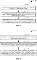
- FIG. 3 illustrates a method 100 for performing an X rotation of a qubit.
- the qubit is configured to be responsive to the continuous microwave tone to produce a Rabi oscillation within the qubit. Further, a portion of an energy spectrum of the qubit is responsive to an applied flux.
- a continuous microwave tone is provided to the qubit to induce the Rabi oscillation in the qubit.
- a flux pulse is provided to the qubit as to tune the energy spectrum of the qubit to a frequency of the Rabi oscillation for a predetermined time. For example, a ground-to-first excited state transition frequency of the qubit can be tuned to the frequency of the Rabi oscillation.
- the flux pulse is adjusted to detune the energy spectrum of the qubit from the frequency of the Rabi oscillation after the predetermined time.
- the predetermined time is equal to a ratio of a desired angle of the X rotation to the frequency of the Rabi oscillation.
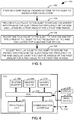
- FIG. 4 illustrates a first method 130 for performing a Y rotation of a qubit.
- the qubit is configured to be responsive to the continuous microwave tone to produce a Rabi oscillation within the qubit. Further, a portion of an energy spectrum of the qubit is responsive to an applied flux.
- the method utilizes a symmetrical detuning, with a first flux pulse providing a first detuning followed immediately by a second flux pulse providing a detuning equal in magnitude and duration but opposite in direction.
- a continuous microwave tone is provided to the qubit.
- a flux pulse is provided to the qubit as to detune the energy spectrum of the qubit from a frequency of the Rabi oscillation by a first predetermined amount for a predetermined time.
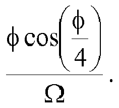
- a ground-to-first excited state transition frequency of the qubit can be detuned from the frequency of the Rabi oscillation by the predetermined amount, equal to ⁇ tan ⁇ 4 , for a time equal to ⁇ cos ⁇ 4 ⁇ , where ⁇ is a desired angle of the Y rotation, and ⁇ is the frequency of the Rabi oscillation.
- the flux pulse to the qubit is adjusted as to detune the energy spectrum of the qubit from a frequency of the Rabi oscillation by a second predetermined amount equal to the additive inverse of the first predetermined amount, for the same time period. Accordingly, in the example given previously, the energy spectrum would be detuned from the Rabi oscillation by an amount ⁇ ⁇ tan ⁇ 4 for a time equal to ⁇ cos ⁇ 4 ⁇ .
- FIG. 5 illustrates a second method 150 for performing a Y rotation of a qubit.
- the qubit is configured to be responsive to the continuous microwave tone to produce a Rabi oscillation within the qubit. Further, a portion of an energy spectrum of the qubit is responsive to an applied flux.
- the method utilizes a modified symmetrical detuning, with a first flux pulse providing a first detuning followed after a delay, during which the spectrum is tuned to the Rabi frequency, by a second flux pulse providing a detuning equal in magnitude and duration but opposite in direction.
- a continuous microwave tone is provided to the qubit.
- a flux pulse is provided to the qubit as to detune the energy spectrum of the qubit from a frequency of the Rabi oscillation by a first predetermined amount for a first predetermined time.
- a ground-to-first excited state transition frequency of the qubit can be detuned from the frequency of the Rabi oscillation by the predetermined amount, equal to ⁇ tan ⁇ 2 , for a time equal to ⁇ cos ⁇ 2 ⁇ , where ⁇ is a desired angle of the Y rotation, and ⁇ is the frequency of the Rabi oscillation.
- the flux pulse to the qubit is adjusted as to tune the energy spectrum of the qubit to the frequency of the Rabi oscillation.
- the energy spectrum can be tuned to the Rabi frequency for a second predetermined time. In the example given previously, this second predetermined time can be equal to ⁇ ⁇ .
- the flux pulse to the qubit is adjusted as to detune the energy spectrum of the qubit from a frequency of the Rabi oscillation by a second predetermined amount equal to the additive inverse of the first predetermined amount, for the same time period, that is, the first predetermined time.
- the energy spectrum would be detuned from the Rabi oscillation by an amount ⁇ ⁇ tan ⁇ 2 for a time equal to ⁇ cos ⁇ 2 ⁇ .
- this method 150 trades a factor of two in the rotation angle ⁇ for a two-fold increase in detuning noise immunity.
- FIG. 6 is a schematic block diagram illustrating an exemplary system 200 of hardware components capable of implementing examples of the systems and methods disclosed in FIGS. 1-5 , such as the system control 18 of FIG. 1 .
- the system 200 can include various systems and subsystems.
- the system 200 can be a personal computer, a laptop computer, a workstation, a computer system, an appliance, an application-specific integrated circuit (ASIC), a server, a server blade center, a server farm, etc.
- ASIC application-specific integrated circuit
- the system 200 can includes a system bus 202, a processing unit 204, a system memory 206, memory devices 208 and 210, a communication interface 212 (e.g., a network interface), a communication link 214, a display 216 (e.g., a video screen), and an input device 218 (e.g., a keyboard and/or a mouse).
- the system bus 202 can be in communication with the processing unit 204 and the system memory 206.
- the additional memory devices 208 and 210 such as a hard disk drive, server, stand-alone database, or other non-volatile memory, can also be in communication with the system bus 202.
- the system bus 202 interconnects the processing unit 204, the memory devices 206-210, the communication interface 212, the display 216, and the input device 218. In some examples, the system bus 202 also interconnects an additional port (not shown), such as a universal serial bus (USB) port.
- USB universal serial bus
- the processing unit 204 can be a computing device and can include an application-specific integrated circuit (ASIC).
- the processing unit 204 executes a set of instructions to implement the operations of examples disclosed herein.
- the processing unit can include a processing core.
- the additional memory devices 206, 208 and 210 can store data, programs, instructions, database queries in text or compiled form, and any other information that can be needed to operate a computer.
- the memories 206, 208 and 210 can be implemented as computer-readable media (integrated or removable) such as a memory card, disk drive, compact disk (CD), or server accessible over a network.
- the memories 206, 208 and 210 can comprise text, images, video, and/or audio, portions of which can be available in formats comprehensible to human beings.
- system 200 can access an external data source or query source through the communication interface 212, which can communicate with the system bus 202 and the communication link 214.
- the system 200 can be used to implement one or more parts of a system control for monitoring and controlling a quantum computing system.
- Computer executable logic for implementing the system control 126 resides on one or more of the system memory 206, and the memory devices 208, 210 in accordance with certain examples.
- the processing unit 204 executes one or more computer executable instructions originating from the system memory 206 and the memory devices 208 and 210.
- the term "computer readable medium” as used herein refers to a medium that participates in providing instructions to the processing unit 204 for execution, and can include either a single medium or multiple non-transitory media operatively connected to the processing unit 204.
- a quantum system comprising:
- the qubit is a transmon qubit.
- the flux source is implemented as a single flux quantum logic circuit.
- the system comprises a system control configured to control the flux source as to selectively apply flux to the qubit, such that a qubit resonance frequency associated with the energy spectrum of the qubit can be selectively tuned to a frequency of the Rabi oscillation.
- the system control is configured to tune the qubit resonance frequency to the frequency of the Rabi oscillation for a predetermined period of time, such that an X rotation of the qubit state is achieved.
- the predetermined time is equal to a ratio of a desired angle of the X rotation to the frequency of the Rabi oscillation.
- the system control is configured to tune the qubit resonance frequency such that the detuning is pulsed symmetrically around a zero point, such that the qubit resonant frequency is detuned from the frequency of the Rabi oscillation by a first amount for a predetermined period of time and then detuned from the frequency of the Rabi oscillation by a second amount for the predetermined period of time, where the second amount is the additive inverse of the first amount.
- the system control is configured such that the predetermined time is equal to ⁇ cos ⁇ 4 ⁇ , where ⁇ is a desired angle of the Y rotation, and ⁇ is the frequency of the Rabi oscillation.
- the system control is configured such that the first amount is equal to ⁇ tan ⁇ 4 , where ⁇ is a desired angle of the Y rotation, and ⁇ is the frequency of the Rabi oscillation.
- the system control is configured to tune the qubit resonance frequency such that the detuning is pulsed symmetrically around a zero point, such that the qubit resonant frequency is detuned from the frequency of the Rabi oscillation by a first amount for a first predetermined period of time, tuned to the frequency of the Rabi oscillation for a second predetermined period of time, and then detuned from the frequency of the Rabi oscillation by a second amount for the first predetermined period of time, where the second amount is the additive inverse of the first amount.
- the system control is configured such that the first predetermined time is equal to ⁇ cos ⁇ 2 ⁇ , where ⁇ is a desired angle of the Y rotation, and ⁇ is the frequency of the Rabi oscillation.
- the system control is configured such that the first amount is equal to ⁇ tan ⁇ 2 , where ⁇ is a desired angle of the Y rotation, and ⁇ is the frequency of the Rabi oscillation.
- the system control is configured such that the second predetermined time is equal to ⁇ ⁇ , where ⁇ is the frequency of the Rabi oscillation.
- a method for performing an X rotation of a qubit configured such that the qubit is responsive to the continuous microwave tone to produce a Rabi oscillation within the qubit and a portion of an energy spectrum of the qubit is responsive to an applied flux, the method comprising:
- the predetermined time is equal to a ratio of a desired angle of the X rotation to the frequency of the Rabi oscillation.
- a method for performing a Y rotation of a qubit configured such that the qubit is responsive to the continuous microwave tone to produce a Rabi oscillation within the qubit and a portion of an energy spectrum of the qubit is responsive to an applied flux, the method comprising:
- the predetermined time is equal to ⁇ cos ⁇ 4 ⁇ and the first amount is equal to ⁇ tan ⁇ 4 where ⁇ is a desired angle of the Y rotation, and ⁇ is the frequency of the Rabi oscillation.
- the predetermined time is a first predetermined time and the method further comprises adjusting the flux pulse to the qubit as to tune the energy spectrum of the qubit to the frequency of the Rabi oscillation for a second predetermined time.
- the flux pulse is adjusted to the qubit as to tune the energy spectrum of the qubit to the frequency of the Rabi oscillation after the flux pulse is provided to the qubit and before the flux pulse is adjusted as to detune the energy spectrum of the qubit from a frequency of the Rabi oscillation by a second predetermined amount.
- the first predetermined time is equal to ⁇ cos ⁇ 2 ⁇
- the first amount is equal to ⁇ tan ⁇ 2
- the second predetermined time is equal to ⁇ ⁇ , where ⁇ is a desired angle of the Y rotation, and ⁇ is the frequency of the Rabi oscillation.
Landscapes
- Engineering & Computer Science (AREA)
- Physics & Mathematics (AREA)
- General Physics & Mathematics (AREA)
- Theoretical Computer Science (AREA)
- Computing Systems (AREA)
- Mathematical Optimization (AREA)
- Artificial Intelligence (AREA)
- Computational Mathematics (AREA)
- Condensed Matter Physics & Semiconductors (AREA)
- Data Mining & Analysis (AREA)
- Evolutionary Computation (AREA)
- Software Systems (AREA)
- Mathematical Analysis (AREA)
- Mathematical Physics (AREA)
- Pure & Applied Mathematics (AREA)
- General Engineering & Computer Science (AREA)
- Electromagnetism (AREA)
- Signal Processing (AREA)
- Computer Networks & Wireless Communication (AREA)
- Optics & Photonics (AREA)
- Superconductor Devices And Manufacturing Methods Thereof (AREA)
Abstract
Description
- This invention was made with Government support under Contract No. SAP PO 30059298. The Government has certain rights in this invention.
- This application claims priority from
U.S. Patent Application No. 14/616473, filed 6 February 2015 - The invention relates generally to quantum computing, and more specifically, to flux control of qubit under resonant excitation.
- Quantum information processing requires large numbers and high densities of qubits to implement quantum algorithms, and even greater amounts of classical control and readout hardware to operate the qubits. In the field of superconducting qubits, there is a need for high density, cryogenic hardware capable of the control and readout of qubits. The qubit with the current record for coherence times and process fidelities, the transmon, is currently controlled with bulky room temperature microwave equipment.
- In one example, a system is provided for flux control of a qubit. A quantum system includes a microwave transmitter configured to provide a continuous microwave tone, and a qubit configured such that a portion of an energy spectrum of the qubit is responsive to an applied flux. The qubit also has an inductive element responsive to the continuous microwave tone to produce a Rabi oscillation within the qubit. A flux source is configured to apply a flux to the qubit.
- In another example, a method is provided for performing an X rotation of a qubit. The qubit is configured such that the qubit is responsive to the continuous microwave tone to produce a Rabi oscillation within the qubit and a portion of an energy spectrum of the qubit is responsive to an applied flux. A continuous microwave tone is provided to the qubit. A flux pulse is provided to the qubit as to tune the energy spectrum of the qubit to a frequency of the Rabi oscillation for a predetermined time. The flux pulse is adjusted to detune the energy spectrum of the qubit from the frequency of the Rabi oscillation after the predetermined time.
- In yet another example, a method is provided for performing a Y rotation of a qubit. The qubit is configured such that the qubit is responsive to the continuous microwave tone to produce a Rabi oscillation within the qubit and a portion of an energy spectrum of the qubit is responsive to an applied flux. A continuous microwave tone is provided to the qubit. A flux pulse is provided to the qubit as to detune the energy spectrum of the qubit from a frequency of the Rabi oscillation by a first predetermined amount for a predetermined time. The flux pulse to the qubit is adjusted as to detune the energy spectrum of the qubit from a frequency of the Rabi oscillation by a second predetermined amount for the predetermined time. The second predetermined amount is the additive inverse of the first predetermined amount.
- The features, objects, and advantages of the invention will become more apparent from the detailed description set forth below when taken in conjunction with the drawings, wherein:
-
FIG. 1 illustrates a quantum system for controlling a state of at least one qubit; -
FIG. 2 illustrates one example of a qubit assembly that could be used in the quantum system ofFIG. 1 , specifically a split junction transmon qubit assembly; -
FIG. 3 illustrates a method for performing an X rotation of a qubit; -
FIG. 4 illustrates a first method for performing a Y rotation of a qubit; -
FIG. 5 illustrates a second method for performing a Y rotation of a qubit; and -
FIG. 6 illustrates a schematic block diagram illustrating an exemplary system of hardware components capable of implementing examples of the systems and methods disclosed inFIGS. 1-5 . - In general, phase and amplitude modulated burst of microwaves have been used to control transmon qubits. These systems require two high sample rate arbitrary waveform channels and a series of bulky room temperature microwave components per qubit. The proposed system and methods allows for the control of a superconducting qubit using a single waveform channel capable of making a square wave pulse, rather than the traditional shaped microwave burst. This control method is compatible with Single Flux Quantum (SFQ) systems, which can generate the control signals on chip at cryogenic temperatures, improving the scalability of the qubit control hardware. Accordingly, the system can eliminate the need for room temperature signal generation or sophisticated microwave techniques through the use of continuous resonant microwave excitations and quasi-static flux pulses to achieve orthogonal, universal control of a single qubit precise control of a superconducting qubit with a Single Flux Quantum (SFQ) style flux.
-
FIG. 1 illustrates aquantum system 10 for controlling a state of at least onequbit 12. In the illustratedsystem 10, thequbit 12 is configured such that a portion of an energy spectrum of the qubit is responsive to an applied flux. Specifically, at least a portion of the energy spectrum of the qubit must be linearly dependent on an applied flux. Examples of such qubits include flux qubits and transmon qubits. Further, thequbit 12 includes an inductive element (not shown) responsive to a continuous microwave tone to produce a coherent Rabi oscillation within the qubit. To this end, thesystem 10 further includes amicrowave transmitter 14 configured to provide a continuous microwave tone to the qubit. When themicrowave transmitter 14 is active, a Rabi oscillation having a known frequency is induced within the qubit. It will be appreciated that themicrowave transmitter 14 can be located outside of a cryogenic portion of thesystem 10, and is capable of broadcasting to multiple qubits. - The illustrated
system 10 allows thequbit 12 to be controlled using flux pulses instead of shaped microwave bursts. Accordingly, thesystem 10 includes aflux source 16 controlled by asystem control 18 as to selectively apply flux to the qubit, such that a qubit resonance frequency associated with the energy spectrum of the qubit can be selectively tuned to a frequency of the Rabi oscillation. In one implementation, one or both of theflux source 16 and thesystem control 18 are implemented as a single flux quantum (SFQ) logic circuit. In general, theflux source 16 tunes a transition energy, and thus an accompanying characteristic frequency, between a ground state of thequbit 12 and a first excited state. Accordingly, this transition can be tuned relative to the Rabi frequency, as to rotate the state of qubit along one of two orthogonal axes. In practice, theflux source 16 can be located within the cryogenic portion of the system with the qubit, with thesystem control 18 located outside of this region. It will be appreciated that thesystem control 18 can be implemented as software executed by a general-purpose processor, dedicated hardware, or a mix of software and dedicated hardware. - In the rotating frame, the single qubit Hamiltonian can be written as

- The presence of the always on tone results in a population of the second excited state due to off resonant excitation of the two photon transition between ground and the second excited state and the single photon transition between the first and second excited states. Unlike existing microwave burst control, there is no resonant excitation due to Fourier side peaks on the microwave burst; since the tone here is continuous, its spectrum is free of spurs. A steady state population of the second excited states state depends on the Rabi oscillation frequency, the amplitude of the microwave tone, and an anharmonicity of the qubit states. The population is, for a given frequency and anharmonicity, directly proportional to the signal amplitude, and is lower for lower Rabi oscillation frequencies. The leakage is dramatically reduced with increases in the anharmonicity.
- In one implementation, the
system control 18 is configured to tune thequbit 12 resonance frequency to the frequency of the Rabi oscillation for a predetermined period of time. When the transition frequency of thequbit 12 is tuned to the frequency of the Rabi oscillation, the qubit rotates around an X-axis of the Bloch sphere, changing the state of the qubit. The time for which the qubit is in tune to the Rabi frequency can be predetermined according to a desired angle of the rotation, such that a controlled X rotation of the qubit state is achieved. Specifically, this predetermined time is equal to a ratio of a desired angle of the X rotation to the frequency of the Rabi oscillation. - In another implementation, the
system control 18 is configured to tune the transition frequency of thequbit 12 such that the qubit is selectively detuned. Specifically, the detuning is pulsed symmetrically around a zero point, such that the qubit resonant frequency is detuned from the frequency of the Rabi oscillation by a first amount for a predetermined period of time and then detuned from the frequency of the Rabi oscillation by a second amount for the predetermined period of time, with the second amount is the additive inverse of the first amount. This results in a rotation around the Y-axis of the Bloch sphere, with the amount of the Y rotation being controlled by the length of the pulse and the amount of the deflection. In one implementation, the predetermined time can be determined as

- In still another implementation, the system control is configured to tune the qubit resonance frequency such that the detuning is pulsed symmetrically around a zero point with a delay, such that the qubit resonant frequency is detuned from the frequency of the Rabi oscillation by a first amount for a first predetermined period of time, tuned to the frequency of the Rabi oscillation for a second predetermined period of time, and then detuned from the frequency of the Rabi oscillation by a second amount for the first predetermined period of time, where the second amount is the additive inverse of the first amount. In one example, the times for which the qubit is detuned is equal to


-
FIG. 2 illustrates one example of aqubit assembly 50 that could be used in the quantum system ofFIG. 1 , specifically a split junction transmon qubit assembly. It will be appreciated, however, that this is not an exclusive example, and that any qubit with at least a portion of its energy spectrum that is responsive to a received flux could be used including at least transmon qubits of other configurations, flux qubits, and phase qubits. The illustratedtunable transmon assembly 50 includes afirst capacitor 52, having a capacitance, C, on a first path between a transmission line and a circuit ground. Second andthird Josephson junctions qubit assembly 50. The DC SQUID is arranged in parallel with thefirst capacitor 52. Asecond capacitor 62 is arranged in parallel with the first Josephson junction and the DC SQUID on a third path between a transmission line and a circuit ground. - The tunable
transmon qubit assembly 50 includes aninductive element 64 that receives flux pulses to tune the energy spectrum of the qubit. In the illustrated implementation, the flux pulse is provided to theDC SQUID 60, but one of skill in the art will appreciate that the pulses could be applied to thequbit assembly 50 in a similar fashion. - In view of the foregoing structural and functional features described above, methods in accordance with various aspects of the present invention will be better appreciated with reference to
FIGS. 3-5 . While, for purposes of simplicity of explanation, the methods ofFIGS. 3-5 are shown and described as executing serially, it is to be understood and appreciated that the present invention is not limited by the illustrated order, as some aspects could, in accordance with the present invention, occur in different orders and/or concurrently with other aspects from that shown and described herein. Moreover, not all illustrated features may be required to implement a method in accordance with an aspect the present invention. -
FIG. 3 illustrates amethod 100 for performing an X rotation of a qubit. In the illustratedmethod 100, the qubit is configured to be responsive to the continuous microwave tone to produce a Rabi oscillation within the qubit. Further, a portion of an energy spectrum of the qubit is responsive to an applied flux. At 102, a continuous microwave tone is provided to the qubit to induce the Rabi oscillation in the qubit. At 104, a flux pulse is provided to the qubit as to tune the energy spectrum of the qubit to a frequency of the Rabi oscillation for a predetermined time. For example, a ground-to-first excited state transition frequency of the qubit can be tuned to the frequency of the Rabi oscillation. At 106, the flux pulse is adjusted to detune the energy spectrum of the qubit from the frequency of the Rabi oscillation after the predetermined time. In one implementation, the predetermined time is equal to a ratio of a desired angle of the X rotation to the frequency of the Rabi oscillation. -
FIG. 4 illustrates afirst method 130 for performing a Y rotation of a qubit. In the illustratedmethod 130, the qubit is configured to be responsive to the continuous microwave tone to produce a Rabi oscillation within the qubit. Further, a portion of an energy spectrum of the qubit is responsive to an applied flux. The method utilizes a symmetrical detuning, with a first flux pulse providing a first detuning followed immediately by a second flux pulse providing a detuning equal in magnitude and duration but opposite in direction. At 132, a continuous microwave tone is provided to the qubit. At 134, a flux pulse is provided to the qubit as to detune the energy spectrum of the qubit from a frequency of the Rabi oscillation by a first predetermined amount for a predetermined time. For example, a ground-to-first excited state transition frequency of the qubit can be detuned from the frequency of the Rabi oscillation by the predetermined amount, equal to


-
FIG. 5 illustrates asecond method 150 for performing a Y rotation of a qubit. In the illustratedmethod 150, the qubit is configured to be responsive to the continuous microwave tone to produce a Rabi oscillation within the qubit. Further, a portion of an energy spectrum of the qubit is responsive to an applied flux. The method utilizes a modified symmetrical detuning, with a first flux pulse providing a first detuning followed after a delay, during which the spectrum is tuned to the Rabi frequency, by a second flux pulse providing a detuning equal in magnitude and duration but opposite in direction. At 152, a continuous microwave tone is provided to the qubit. At 154, a flux pulse is provided to the qubit as to detune the energy spectrum of the qubit from a frequency of the Rabi oscillation by a first predetermined amount for a first predetermined time. For example, a ground-to-first excited state transition frequency of the qubit can be detuned from the frequency of the Rabi oscillation by the predetermined amount, equal to

- At 156, the flux pulse to the qubit is adjusted as to tune the energy spectrum of the qubit to the frequency of the Rabi oscillation. The energy spectrum can be tuned to the Rabi frequency for a second predetermined time. In the example given previously, this second predetermined time can be equal to


method 130 shown inFIG. 4 , thismethod 150 trades a factor of two in the rotation angle φ for a two-fold increase in detuning noise immunity. -
FIG. 6 is a schematic block diagram illustrating anexemplary system 200 of hardware components capable of implementing examples of the systems and methods disclosed inFIGS. 1-5 , such as thesystem control 18 ofFIG. 1 . Thesystem 200 can include various systems and subsystems. Thesystem 200 can be a personal computer, a laptop computer, a workstation, a computer system, an appliance, an application-specific integrated circuit (ASIC), a server, a server blade center, a server farm, etc. - The
system 200 can includes asystem bus 202, aprocessing unit 204, asystem memory 206,memory devices communication link 214, a display 216 (e.g., a video screen), and an input device 218 (e.g., a keyboard and/or a mouse). Thesystem bus 202 can be in communication with theprocessing unit 204 and thesystem memory 206. Theadditional memory devices system bus 202. Thesystem bus 202 interconnects theprocessing unit 204, the memory devices 206-210, thecommunication interface 212, thedisplay 216, and theinput device 218. In some examples, thesystem bus 202 also interconnects an additional port (not shown), such as a universal serial bus (USB) port. - The
processing unit 204 can be a computing device and can include an application-specific integrated circuit (ASIC). Theprocessing unit 204 executes a set of instructions to implement the operations of examples disclosed herein. The processing unit can include a processing core. - The
additional memory devices memories memories - Additionally or alternatively, the
system 200 can access an external data source or query source through thecommunication interface 212, which can communicate with thesystem bus 202 and thecommunication link 214. - In operation, the
system 200 can be used to implement one or more parts of a system control for monitoring and controlling a quantum computing system. Computer executable logic for implementing the system control 126 resides on one or more of thesystem memory 206, and thememory devices processing unit 204 executes one or more computer executable instructions originating from thesystem memory 206 and thememory devices processing unit 204 for execution, and can include either a single medium or multiple non-transitory media operatively connected to theprocessing unit 204. - The invention has been disclosed illustratively. Accordingly, the terminology employed throughout the disclosure should be read in an exemplary rather than a limiting manner. Although minor modifications of the invention will occur to those well versed in the art, it shall be understood that what is intended to be circumscribed within the scope of the patent warranted hereon are all such embodiments that reasonably fall within the scope of the advancement to the art hereby contributed, and that that scope shall not be restricted, except in light of the appended claims and their equivalents.
- Additional aspects of the invention are set out below.
- A quantum system comprising:
- a microwave transmitter configured to provide a continuous microwave tone;
- a qubit configured such that a portion of an energy spectrum of the qubit is responsive to an applied flux, the qubit having an inductive element responsive to the continuous microwave tone to produce a Rabi oscillation within the qubit; and
- a flux source configured to apply a flux to the qubit.
- Preferably, the qubit is a transmon qubit.
- Preferably, the flux source is implemented as a single flux quantum logic circuit.
- Preferably, the system comprises a system control configured to control the flux source as to selectively apply flux to the qubit, such that a qubit resonance frequency associated with the energy spectrum of the qubit can be selectively tuned to a frequency of the Rabi oscillation.
- Preferably, the system control is configured to tune the qubit resonance frequency to the frequency of the Rabi oscillation for a predetermined period of time, such that an X rotation of the qubit state is achieved.
- Preferably, the predetermined time is equal to a ratio of a desired angle of the X rotation to the frequency of the Rabi oscillation.
- Preferably, the system control is configured to tune the qubit resonance frequency such that the detuning is pulsed symmetrically around a zero point, such that the qubit resonant frequency is detuned from the frequency of the Rabi oscillation by a first amount for a predetermined period of time and then detuned from the frequency of the Rabi oscillation by a second amount for the predetermined period of time, where the second amount is the additive inverse of the first amount.
- Preferably, the system control is configured such that the predetermined time is equal to

- Preferably, the system control is configured such that the first amount is equal to

- Preferably, the system control is configured to tune the qubit resonance frequency such that the detuning is pulsed symmetrically around a zero point, such that the qubit resonant frequency is detuned from the frequency of the Rabi oscillation by a first amount for a first predetermined period of time, tuned to the frequency of the Rabi oscillation for a second predetermined period of time, and then detuned from the frequency of the Rabi oscillation by a second amount for the first predetermined period of time, where the second amount is the additive inverse of the first amount.
- Preferably, the system control is configured such that the first predetermined time is equal to

- Preferably, the system control is configured such that the first amount is equal to

- Preferably, the system control is configured such that the second predetermined time is equal to

- A method for performing an X rotation of a qubit configured such that the qubit is responsive to the continuous microwave tone to produce a Rabi oscillation within the qubit and a portion of an energy spectrum of the qubit is responsive to an applied flux, the method comprising:
- providing a continuous microwave tone to the qubit;
- providing a flux pulse to the qubit as to tune the energy spectrum of the qubit to a frequency of the Rabi oscillation for a predetermined time; and
- adjusting the flux pulse to detune the energy spectrum of the qubit from the frequency of the Rabi oscillation after the predetermined time.
- Preferably, the predetermined time is equal to a ratio of a desired angle of the X rotation to the frequency of the Rabi oscillation.
- A method for performing a Y rotation of a qubit configured such that the qubit is responsive to the continuous microwave tone to produce a Rabi oscillation within the qubit and a portion of an energy spectrum of the qubit is responsive to an applied flux, the method comprising:
- providing a continuous microwave tone to the qubit;
- providing a flux pulse to the qubit as to detune the energy spectrum of the qubit from a frequency of the Rabi oscillation by a first predetermined amount for a predetermined time; and
- adjusting the flux pulse to the qubit as to detune the energy spectrum of the qubit from a frequency of the Rabi oscillation by a second predetermined amount for the predetermined time, wherein the second predetermined amount is the additive inverse of the first predetermined amount.
- Preferably, the predetermined time is equal to


- Preferably, the predetermined time is a first predetermined time and the method further comprises adjusting the flux pulse to the qubit as to tune the energy spectrum of the qubit to the frequency of the Rabi oscillation for a second predetermined time.
- Preferably, the flux pulse is adjusted to the qubit as to tune the energy spectrum of the qubit to the frequency of the Rabi oscillation after the flux pulse is provided to the qubit and before the flux pulse is adjusted as to detune the energy spectrum of the qubit from a frequency of the Rabi oscillation by a second predetermined amount.
- Preferably, the first predetermined time is equal to


Claims (8)
- A quantum system comprising:a microwave transmitter configured to provide a continuous microwave tone;a qubit configured such that a portion of an energy spectrum of the qubit is responsive to an applied flux, the qubit having an inductive element responsive to the continuous microwave tone to produce a Rabi oscillation within the qubit;a flux source configured to apply a flux to the qubit; anda system control configured to:control the flux source as to selectively apply flux to the qubit, such that a qubit resonance frequency associated with the energy spectrum of the qubit can be selectively tuned to a frequency of the Rabi oscillation; andtune the qubit resonance frequency to the frequency of the Rabi oscillation for a predetermined period of time, such that an X rotation of the qubit state is achieved, wherein the predetermined time is equal to a ratio of a desired angle of the X rotation to the frequency of the Rabi oscillation.
- The quantum system of claim 1, wherein the qubit is a transmon qubit.
- The quantum system of claim 1, wherein the flux source is implemented as a single flux quantum logic circuit.
- The quantum system of claim 1, wherein the qubit is a first qubit, the quantum system further comprising a second qubit, and the microwave transmitter being configured to provide the continuous microwave tone to each of the first qubit and the second qubit.
- The quantum system of claim 1, wherein each of the qubit and the flux source are located within a cryogenic portion of the quantum system and the microwave transmitter is located outside of the cryogenic portion of the quantum system.
- A method for performing an X rotation of a qubit configured such that the qubit is responsive to the continuous microwave tone to produce a Rabi oscillation within the qubit and a portion of an energy spectrum of the qubit is responsive to an applied flux, the method comprising:providing a continuous microwave tone to the qubit;providing a flux pulse to the qubit as to tune a qubit resonance frequency associated with the energy spectrum of the qubit to a frequency of the Rabi oscillation for a predetermined time; andadjusting the flux pulse to detune the qubit resonance frequency associated with the energy spectrum of the qubit away from the frequency of the Rabi oscillation after the predetermined time equal to a ratio of a desired angle of the X rotation to the frequency of the Rabi oscillation.
- The method of claim 6, wherein the qubit is a transmon qubit.
- The method of claim 6, wherein the flux source is implemented as a single flux quantum logic circuit.
Applications Claiming Priority (3)
| Application Number | Priority Date | Filing Date | Title |
|---|---|---|---|
| US14/616,473 US10650319B2 (en) | 2015-02-06 | 2015-02-06 | Flux control of qubit under resonant excitation |
| PCT/US2016/016625 WO2016126979A1 (en) | 2015-02-06 | 2016-02-04 | Flux control of qubit under resonant excitation |
| EP16706466.6A EP3254241B1 (en) | 2015-02-06 | 2016-02-04 | Flux control of qubit under resonant excitation |
Related Parent Applications (2)
| Application Number | Title | Priority Date | Filing Date |
|---|---|---|---|
| EP16706466.6A Division-Into EP3254241B1 (en) | 2015-02-06 | 2016-02-04 | Flux control of qubit under resonant excitation |
| EP16706466.6A Division EP3254241B1 (en) | 2015-02-06 | 2016-02-04 | Flux control of qubit under resonant excitation |
Publications (2)
| Publication Number | Publication Date |
|---|---|
| EP3576025A1 true EP3576025A1 (en) | 2019-12-04 |
| EP3576025B1 EP3576025B1 (en) | 2022-07-27 |
Family
ID=55436161
Family Applications (2)
| Application Number | Title | Priority Date | Filing Date |
|---|---|---|---|
| EP19187630.9A Active EP3576025B1 (en) | 2015-02-06 | 2016-02-04 | Flux control of qubit under resonant excitation |
| EP16706466.6A Active EP3254241B1 (en) | 2015-02-06 | 2016-02-04 | Flux control of qubit under resonant excitation |
Family Applications After (1)
| Application Number | Title | Priority Date | Filing Date |
|---|---|---|---|
| EP16706466.6A Active EP3254241B1 (en) | 2015-02-06 | 2016-02-04 | Flux control of qubit under resonant excitation |
Country Status (7)
| Country | Link |
|---|---|
| US (2) | US10650319B2 (en) |
| EP (2) | EP3576025B1 (en) |
| JP (2) | JP6415737B2 (en) |
| KR (1) | KR102035149B1 (en) |
| AU (1) | AU2016215234B2 (en) |
| CA (1) | CA2974106C (en) |
| WO (1) | WO2016126979A1 (en) |
Families Citing this family (32)
| Publication number | Priority date | Publication date | Assignee | Title |
|---|---|---|---|---|
| US10650319B2 (en) | 2015-02-06 | 2020-05-12 | Northrop Grumman Systems Corporation | Flux control of qubit under resonant excitation |
| JP2018513452A (en) | 2015-02-27 | 2018-05-24 | イェール ユニバーシティーYale University | Techniques and related systems and methods for universal quantum control of quantum coherent states |
| KR20170123657A (en) | 2015-02-27 | 2017-11-08 | 예일 유니버시티 | Oscillator control technology for quantum information processing and related systems and methods |
| CA2993006C (en) * | 2015-07-24 | 2023-10-03 | Yale University | Techniques of oscillator state manipulation for quantum information processing and related systems and methods |
| CN108290733B (en) | 2015-12-04 | 2022-04-26 | 耶鲁大学 | Techniques for quantum error correction using boson mode and related systems and methods |
| GB2553848B (en) * | 2016-09-19 | 2022-06-22 | Royal Holloway & Bedford New College | Quantum power sensor |
| US10776709B2 (en) | 2016-11-10 | 2020-09-15 | Yale University | Generalized quantum channels |
| CN110073375B (en) * | 2016-12-13 | 2023-08-25 | 谷歌有限责任公司 | Compensation pulse for qubit readout |
| US10176432B2 (en) * | 2017-03-07 | 2019-01-08 | International Business Machines Corporation | Weakly tunable qubit based on two coupled disparate transmons |
| WO2019055430A1 (en) * | 2017-09-12 | 2019-03-21 | Irwin Klee M | Topological quantum computing apparatus, system, and method |
| US10332023B2 (en) * | 2017-09-22 | 2019-06-25 | International Business Machines Corporation | Hardware-efficient variational quantum eigenvalue solver for quantum computing machines |
| US10756712B2 (en) | 2017-11-13 | 2020-08-25 | Northrop Grumman Systems Corporation | RQL phase-mode flip-flop |
| WO2019156759A2 (en) | 2018-01-05 | 2019-08-15 | Yale University | Robust quantum logical gates |
| US11782779B2 (en) | 2018-01-05 | 2023-10-10 | Yale University | Techniques for error correction of a logical qubit and related systems and methods |
| US10554207B1 (en) | 2018-07-31 | 2020-02-04 | Northrop Grumman Systems Corporation | Superconducting non-destructive readout circuits |
| US10510943B1 (en) | 2018-08-28 | 2019-12-17 | International Business Machines Corporation | Structure for an antenna chip for qubit annealing |
| US10475983B1 (en) | 2018-08-28 | 2019-11-12 | International Business Machines Corporation | Antenna-based qubit annealing method |
| US11050009B2 (en) | 2018-08-28 | 2021-06-29 | International Business Machines Corporation | Methods for annealing qubits with an antenna chip |
| US11121302B2 (en) | 2018-10-11 | 2021-09-14 | SeeQC, Inc. | System and method for superconducting multi-chip module |
| US10726351B1 (en) * | 2019-02-01 | 2020-07-28 | Wisconsin Alumni Research Foundation | System and method for controlling superconducting qubits using single flux quantum logic |
| US11909451B2 (en) | 2019-03-28 | 2024-02-20 | Yale University | Error correction while maintaining bosonic nature of the system |
| US11461688B2 (en) * | 2019-05-22 | 2022-10-04 | IonQ, Inc. | Simultaneously entangling gates for trapped-ion quantum computers |
| EP3997608A4 (en) * | 2019-07-12 | 2023-07-26 | D-Wave Systems Inc. | Systems and methods for simulating a quantum processor |
| CN112444714B (en) * | 2019-08-28 | 2023-04-25 | 合肥本源量子计算科技有限责任公司 | Quantum bit working parameter detection method |
| US11695483B2 (en) | 2020-02-19 | 2023-07-04 | International Business Machines Corporation | Target qubit decoupling in an echoed cross-resonance gate |
| US11201608B2 (en) | 2020-04-24 | 2021-12-14 | Northrop Grumman Systems Corporation | Superconducting latch system |
| CN112149832B (en) * | 2020-10-09 | 2022-05-10 | 腾讯科技(深圳)有限公司 | Frequency control signal processing method of quantum bit, superconducting quantum chip |
| US12048256B2 (en) * | 2021-04-27 | 2024-07-23 | Microsoft Technology Licensing, Llc | Interfacing with superconducting circuitry |
| AU2022289736A1 (en) | 2021-06-11 | 2024-02-01 | Caleb JORDAN | System and method of flux bias for superconducting quantum circuits |
| GB2609443A (en) * | 2021-07-30 | 2023-02-08 | Universal Quantum Ltd | Improvements in or relating to quantum computing |
| EP4453810A4 (en) | 2021-12-22 | 2025-07-23 | Univ Yale | QUANTUM ERROR CORRECTION TECHNIQUES USING MULTIMODAL LATTICE STATES AND CORRESPONDING SYSTEMS AND METHODS |
| WO2025147277A2 (en) * | 2023-03-03 | 2025-07-10 | Google Llc | Implementing quantum logic gates using pulse analysis for quantum computing system |
Citations (2)
| Publication number | Priority date | Publication date | Assignee | Title |
|---|---|---|---|---|
| JP2006165812A (en) * | 2004-12-03 | 2006-06-22 | Nippon Telegr & Teleph Corp <Ntt> | Quantum entangled state control method between quantum circuit and multiple qubit devices |
| US20090289638A1 (en) * | 2008-05-23 | 2009-11-26 | International Business Machines Corporation | Microwave readout for flux-biased qubits |
Family Cites Families (71)
| Publication number | Priority date | Publication date | Assignee | Title |
|---|---|---|---|---|
| US4360898A (en) | 1980-06-30 | 1982-11-23 | International Business Machines Corporation | Programmable logic array system incorporating Josephson devices |
| JPS58135141A (en) | 1982-02-04 | 1983-08-11 | Sumitomo Electric Ind Ltd | Method for manufacturing single polarization optical fiber |
| JPS60163487A (en) | 1984-02-03 | 1985-08-26 | Nec Corp | Semiconductor laser |
| JP2802446B2 (en) | 1989-11-27 | 1998-09-24 | 科学技術振興事業団 | Superconducting logic circuit |
| US5250859A (en) | 1991-09-27 | 1993-10-05 | Kaplinsky Cecil H | Low power multifunction logic array |
| JPH05190922A (en) | 1992-01-09 | 1993-07-30 | Hitachi Ltd | Quantum memory device |
| JPH08148989A (en) | 1994-11-18 | 1996-06-07 | Hitachi Ltd | Superconducting FPGA device |
| JP2688011B2 (en) | 1994-12-16 | 1997-12-08 | 工業技術院長 | Unit circuit for building asynchronous superconducting logic circuits |
| US6026129A (en) * | 1996-03-27 | 2000-02-15 | Matsushita Electric Industrial Co., Ltd. | Radio receiving apparatus for receiving communication signals of different bandwidths |
| US5963351A (en) | 1996-08-23 | 1999-10-05 | Conductus, Inc. | Digital optical receiver with instantaneous Josephson clock recovery circuit |
| JP2000124794A (en) | 1998-10-12 | 2000-04-28 | Science & Tech Agency | Superconductive logic circuit |
| US6734699B1 (en) | 1999-07-14 | 2004-05-11 | Northrop Grumman Corporation | Self-clocked complementary logic |
| WO2002027653A2 (en) | 2000-09-26 | 2002-04-04 | Robert Raussendorf | Method for quantum computing |
| US6420895B1 (en) | 2001-03-23 | 2002-07-16 | Trw Inc. | High-sensitivity, self-clocked receiver for multi-chip superconductor circuits |
| JP2002344306A (en) | 2001-05-17 | 2002-11-29 | Seiko Instruments Inc | Logic gate based on single flux quantum theory |
| JP3806619B2 (en) | 2001-06-15 | 2006-08-09 | 株式会社日立製作所 | Superconducting single flux quantum circuit |
| US6518786B2 (en) | 2001-06-15 | 2003-02-11 | Trw Inc. | Combinational logic using asynchronous single-flux quantum gates |
| US7280623B2 (en) | 2002-08-02 | 2007-10-09 | Hypres, Inc. | Digital RF correlator for multipurpose digital signal processing |
| US6781435B1 (en) | 2003-02-03 | 2004-08-24 | Hypres, Inc. | Apparatus and method for converting a multi-bit signal to a serial pulse stream |
| US20050250651A1 (en) | 2004-03-29 | 2005-11-10 | Amin Mohammad H S | Adiabatic quantum computation with superconducting qubits |
| US7533068B2 (en) | 2004-12-23 | 2009-05-12 | D-Wave Systems, Inc. | Analog processor comprising quantum devices |
| JP4690791B2 (en) | 2005-06-22 | 2011-06-01 | 株式会社日立製作所 | Current signal input type single flux quantum circuit |
| US7554369B2 (en) | 2005-10-04 | 2009-06-30 | Hypres, Inc. | Digital programmable frequency divider |
| US7680474B2 (en) | 2005-10-04 | 2010-03-16 | Hypres Inc. | Superconducting digital mixer |
| US8159825B1 (en) | 2006-08-25 | 2012-04-17 | Hypres Inc. | Method for fabrication of electrical contacts to superconducting circuits |
| EP2100376B1 (en) | 2007-01-18 | 2018-01-10 | Northrop Grumman Systems Corporation | Single flux quantum circuits |
| US7782077B2 (en) | 2007-01-18 | 2010-08-24 | Northrop Grumman Systems Corporation | Method and apparatus for ballistic single flux quantum logic |
| US7843209B2 (en) | 2007-04-25 | 2010-11-30 | D-Wave Systems Inc. | Architecture for local programming of quantum processor elements using latching qubits |
| US7570075B2 (en) | 2007-06-29 | 2009-08-04 | Hypres, Inc. | Ultra fast differential transimpedance digital amplifier for superconducting circuits |
| US7498832B2 (en) | 2007-08-03 | 2009-03-03 | Northrop Grumman Systems Corporation | Arbitrary quantum operations with a common coupled resonator |
| US7893708B2 (en) | 2007-08-03 | 2011-02-22 | Northrop Grumman Systems Corporation | Quantum gate operations with a common coupled resonator |
| US7598897B2 (en) | 2007-12-13 | 2009-10-06 | Hypres, Inc. | Superconductor analog-to-digital converter |
| JP4996521B2 (en) | 2008-03-28 | 2012-08-08 | 本田技研工業株式会社 | Radiator reserve tank arrangement structure for motorcycles |
| US7772871B2 (en) | 2008-04-28 | 2010-08-10 | Northrop Grumman Corporation | Method and apparatus for high density superconductor circuit |
| US7969178B2 (en) * | 2008-05-29 | 2011-06-28 | Northrop Grumman Systems Corporation | Method and apparatus for controlling qubits with single flux quantum logic |
| US7975195B1 (en) | 2008-08-28 | 2011-07-05 | Marvell International Ltd. | Scan architecture for full custom blocks with improved scan latch |
| US7772872B2 (en) | 2008-09-08 | 2010-08-10 | Altera Corporation | Multi-row block supporting row level redundancy in a PLD |
| US7786786B2 (en) | 2008-12-17 | 2010-08-31 | Hypres, Inc. | Multiphase clock for superconducting electronics |
| US7786748B1 (en) | 2009-05-15 | 2010-08-31 | Northrop Grumman Systems Corporation | Method and apparatus for signal inversion in superconducting logic gates |
| CN101626233B (en) | 2009-08-03 | 2011-07-20 | 杭州电子科技大学 | Resistive superconductive asynchronous bilinear logic universal gate circuit |
| CN101626234B (en) | 2009-08-03 | 2011-04-06 | 杭州电子科技大学 | Resistive superconductive asynchronous bilinear logic AND gate circuit |
| US8571614B1 (en) | 2009-10-12 | 2013-10-29 | Hypres, Inc. | Low-power biasing networks for superconducting integrated circuits |
| US8270209B2 (en) | 2010-04-30 | 2012-09-18 | Northrop Grumman Systems Corporation | Josephson magnetic random access memory system and method |
| JP5497596B2 (en) | 2010-09-14 | 2014-05-21 | 日本電信電話株式会社 | Quantum state control method |
| US8242799B2 (en) | 2010-11-16 | 2012-08-14 | Northrop Grumman Systems Corporation | System and method for phase error reduction in quantum systems |
| US8111083B1 (en) | 2010-12-01 | 2012-02-07 | Northrop Grumman Systems Corporation | Quantum processor |
| US8971977B2 (en) | 2011-01-17 | 2015-03-03 | Hypres, Inc. | Superconducting devices with ferromagnetic barrier junctions |
| US8654578B2 (en) | 2011-06-17 | 2014-02-18 | Northrop Grumman Systems Corporation | Phase qubit cell having enhanced coherence |
| US8489163B2 (en) | 2011-08-12 | 2013-07-16 | Northrop Grumman Systems Corporation | Superconducting latch system |
| US9787312B2 (en) | 2012-08-14 | 2017-10-10 | Northrop Grumman Systems Corporation | Systems and methods for applying flux to a quantum-coherent superconducting circuit |
| US8957699B2 (en) | 2012-10-26 | 2015-02-17 | Northrop Grumman Systems Corporation | Efficient Toffoli state generation from low-fidelity single qubit magic states |
| EP2954416B1 (en) | 2013-02-05 | 2021-05-12 | D-Wave Systems, Inc. | Systems and methods for error correction in quantum computation |
| US9350460B2 (en) * | 2013-04-23 | 2016-05-24 | Raytheon Bbn Technologies Corp. | System and method for quantum information transfer between optical photons and superconductive qubits |
| JP6042777B2 (en) * | 2013-06-12 | 2016-12-14 | 日本電信電話株式会社 | Qubit control method |
| US9208861B2 (en) | 2013-10-01 | 2015-12-08 | Northrop Grumman Systems Corporation | Phase hysteretic magnetic Josephson junction memory cell |
| US10037493B2 (en) | 2013-10-22 | 2018-07-31 | D-Wave Systems Inc. | Universal adiabatic quantum computing with superconducting qubits |
| US20160189053A1 (en) | 2014-12-31 | 2016-06-30 | Invent.ly LLC | Freezing a subject's contextualization of a proposition considered in a quantum representation by using a Quantum Zeno effect |
| US9355364B2 (en) | 2014-03-10 | 2016-05-31 | Northrop Grumman Systems Corporation | Reciprocal quantum logic comparator for qubit readout |
| US9369133B2 (en) * | 2014-05-29 | 2016-06-14 | Northrop Grumman Systems Corporation | Hybrid quantum circuit assembly |
| EP3167450B1 (en) | 2014-07-08 | 2020-09-16 | Northrop Grumman Systems Corporation | Superconductive gate system |
| US9292642B2 (en) | 2014-08-01 | 2016-03-22 | Northrop Grumman Systems Corporation | Superconducting circuit physical layout system and method |
| KR101942303B1 (en) | 2014-10-29 | 2019-01-25 | 노스롭 그루먼 시스템즈 코포레이션 | Reciprocal quantum logic (rql) circuit synthesis |
| US10650319B2 (en) | 2015-02-06 | 2020-05-12 | Northrop Grumman Systems Corporation | Flux control of qubit under resonant excitation |
| US9543959B1 (en) | 2015-10-21 | 2017-01-10 | Microsoft Technology Licensing, Llc | Phase-mode based superconducting logic |
| US10311369B2 (en) | 2016-08-01 | 2019-06-04 | Northrop Grumman Systems Corporation | Quantum gates via multi-step adiabatic drag |
| US9812192B1 (en) | 2016-09-02 | 2017-11-07 | Northrop Grumman Systems Corporation | Superconducting gate memory circuit |
| US10158363B1 (en) | 2017-11-13 | 2018-12-18 | Northrop Grumman Systems Corporation | Josephson and/or gate |
| US10171087B1 (en) | 2017-11-13 | 2019-01-01 | Northrop Grumman Systems Corporation | Large fan-in RQL gates |
| US10756712B2 (en) | 2017-11-13 | 2020-08-25 | Northrop Grumman Systems Corporation | RQL phase-mode flip-flop |
| US10158348B1 (en) | 2018-02-01 | 2018-12-18 | Northrop Grumman Systems Corporation | Tri-stable storage loops |
| US10554207B1 (en) | 2018-07-31 | 2020-02-04 | Northrop Grumman Systems Corporation | Superconducting non-destructive readout circuits |
-
2015
- 2015-02-06 US US14/616,473 patent/US10650319B2/en active Active
-
2016
- 2016-02-04 KR KR1020177021776A patent/KR102035149B1/en active Active
- 2016-02-04 WO PCT/US2016/016625 patent/WO2016126979A1/en not_active Ceased
- 2016-02-04 CA CA2974106A patent/CA2974106C/en active Active
- 2016-02-04 AU AU2016215234A patent/AU2016215234B2/en active Active
- 2016-02-04 JP JP2017540149A patent/JP6415737B2/en active Active
- 2016-02-04 EP EP19187630.9A patent/EP3576025B1/en active Active
- 2016-02-04 EP EP16706466.6A patent/EP3254241B1/en active Active
-
2018
- 2018-10-02 JP JP2018187270A patent/JP6771009B2/en active Active
-
2020
- 2020-04-02 US US16/839,011 patent/US11010686B2/en active Active
Patent Citations (2)
| Publication number | Priority date | Publication date | Assignee | Title |
|---|---|---|---|---|
| JP2006165812A (en) * | 2004-12-03 | 2006-06-22 | Nippon Telegr & Teleph Corp <Ntt> | Quantum entangled state control method between quantum circuit and multiple qubit devices |
| US20090289638A1 (en) * | 2008-05-23 | 2009-11-26 | International Business Machines Corporation | Microwave readout for flux-biased qubits |
Non-Patent Citations (5)
| Title |
|---|
| A. LAUCHT ET AL: "Electrically controlling single-spin qubits in a continuous microwave field", SCIENCE, vol. 1, no. 3, 10 April 2015 (2015-04-10), US, pages e1500022 - e1500022, XP055267170, ISSN: 0036-8075, DOI: 10.1126/sciadv.1500022 * |
| DICARLO L ET AL: "Demonstration of Two-Qubit Algorithms with a Superconducting Quantum Processor", ARXIV.ORG, CORNELL UNIVERSITY LIBRARY, 201 OLIN LIBRARY CORNELL UNIVERSITY ITHACA, NY 14853, 11 March 2009 (2009-03-11), XP080314862, DOI: 10.1038/NATURE08121 * |
| JERGER M ET AL: "Frequency division multiplexing readout and simultaneous manipulation of an array of flux qubits", APPLIED PHYSICS LETTERS, A I P PUBLISHING LLC, US, vol. 101, no. 4, 23 July 2012 (2012-07-23), pages 42604 - 42604, XP012164086, ISSN: 0003-6951, [retrieved on 20120727], DOI: 10.1063/1.4739454 * |
| JIAN LI ET AL: "Dynamical Autler-Townes control of a phase qubit", SCIENTIFIC REPORTS, vol. 2, 11 December 2012 (2012-12-11), XP055268241, DOI: 10.1038/srep00645 * |
| JIAN LI ET AL: "Operation of a phase qubit as a quantum switch", ARXIV.ORG, CORNELL UNIVERSITY LIBRARY, 201 OLIN LIBRARY CORNELL UNIVERSITY ITHACA, NY 14853, 14 March 2011 (2011-03-14), XP080543914, DOI: 10.1038/SREP00645 * |
Also Published As
| Publication number | Publication date |
|---|---|
| WO2016126979A1 (en) | 2016-08-11 |
| CA2974106C (en) | 2019-10-01 |
| JP2019047126A (en) | 2019-03-22 |
| US20160233965A1 (en) | 2016-08-11 |
| US20200234173A1 (en) | 2020-07-23 |
| JP2018511848A (en) | 2018-04-26 |
| KR102035149B1 (en) | 2019-10-22 |
| EP3254241B1 (en) | 2019-09-11 |
| US10650319B2 (en) | 2020-05-12 |
| EP3254241A1 (en) | 2017-12-13 |
| EP3576025B1 (en) | 2022-07-27 |
| CA2974106A1 (en) | 2016-08-11 |
| AU2016215234B2 (en) | 2018-12-06 |
| KR20170103866A (en) | 2017-09-13 |
| US11010686B2 (en) | 2021-05-18 |
| AU2016215234A1 (en) | 2017-08-10 |
| JP6771009B2 (en) | 2020-10-21 |
| JP6415737B2 (en) | 2018-10-31 |
Similar Documents
| Publication | Publication Date | Title |
|---|---|---|
| US11010686B2 (en) | Flux control of qubit under resonant excitation | |
| US10572816B1 (en) | System and method for controlling superconducting qubits | |
| Bengtsson et al. | Improved success probability with greater circuit depth for the quantum approximate optimization algorithm | |
| US10719776B1 (en) | Quantum bit multi-state reset | |
| US10056908B2 (en) | Operating a coupler device to perform quantum logic gates | |
| US11790259B2 (en) | Systems and methods for tuning capacitance in quantum devices | |
| EP3192017B1 (en) | Tunable transmon circuit assembly | |
| US10090043B2 (en) | Providing controlled pulses for quantum computing | |
| US11112842B1 (en) | Resetting qubits in a superconducting quantum processor | |
| EP4564236A1 (en) | Method and circuit for implementing two-qubit gate | |
| Bengtsson et al. | Quantum approximate optimization of the exact-cover problem on a superconducting quantum processor | |
| JP2009049631A (en) | Device state readout device, method, and transmission type Josephson resonance circuit | |
| Lundin et al. | Decoherence-Induced Stabilization of the Multiple-Quantum NMR-Spectrum Width | |
| Oi et al. | Quantum system characterization with limited resources | |
| Dzheparov et al. | Nuclear Magnetic Resonance in Gaussian Stochastic Local Field | |
| Das et al. | Experimental implementation of a quantum algorithm in a multiqubit NMR system formed by an oriented 7∕ 2 spin | |
| Deka et al. | A practical under-sampling pattern for compressed sensing MRI | |
| US20240311671A1 (en) | Calibration of iSWAP Gate on a Superconducting Quantum Processing Unit | |
| WO2025177136A1 (en) | Quantum processor architecture | |
| Reuer | Entangling Itinerant Microwave Photons using Superconducting Circuits | |
| Wang et al. | Control of the frozen geometric quantum correlation by applying the time-dependent electromagnetic field |
Legal Events
| Date | Code | Title | Description |
|---|---|---|---|
| PUAI | Public reference made under article 153(3) epc to a published international application that has entered the european phase |
Free format text: ORIGINAL CODE: 0009012 |
|
| STAA | Information on the status of an ep patent application or granted ep patent |
Free format text: STATUS: THE APPLICATION HAS BEEN PUBLISHED |
|
| AC | Divisional application: reference to earlier application |
Ref document number: 3254241 Country of ref document: EP Kind code of ref document: P |
|
| AK | Designated contracting states |
Kind code of ref document: A1 Designated state(s): AL AT BE BG CH CY CZ DE DK EE ES FI FR GB GR HR HU IE IS IT LI LT LU LV MC MK MT NL NO PL PT RO RS SE SI SK SM TR |
|
| STAA | Information on the status of an ep patent application or granted ep patent |
Free format text: STATUS: REQUEST FOR EXAMINATION WAS MADE |
|
| 17P | Request for examination filed |
Effective date: 20200203 |
|
| RBV | Designated contracting states (corrected) |
Designated state(s): AL AT BE BG CH CY CZ DE DK EE ES FI FR GB GR HR HU IE IS IT LI LT LU LV MC MK MT NL NO PL PT RO RS SE SI SK SM TR |
|
| RIN1 | Information on inventor provided before grant (corrected) |
Inventor name: MEDFORD, JAMES R. |
|
| STAA | Information on the status of an ep patent application or granted ep patent |
Free format text: STATUS: EXAMINATION IS IN PROGRESS |
|
| 17Q | First examination report despatched |
Effective date: 20210401 |
|
| GRAP | Despatch of communication of intention to grant a patent |
Free format text: ORIGINAL CODE: EPIDOSNIGR1 |
|
| STAA | Information on the status of an ep patent application or granted ep patent |
Free format text: STATUS: GRANT OF PATENT IS INTENDED |
|
| INTG | Intention to grant announced |
Effective date: 20220304 |
|
| GRAS | Grant fee paid |
Free format text: ORIGINAL CODE: EPIDOSNIGR3 |
|
| GRAA | (expected) grant |
Free format text: ORIGINAL CODE: 0009210 |
|
| STAA | Information on the status of an ep patent application or granted ep patent |
Free format text: STATUS: THE PATENT HAS BEEN GRANTED |
|
| AC | Divisional application: reference to earlier application |
Ref document number: 3254241 Country of ref document: EP Kind code of ref document: P |
|
| AK | Designated contracting states |
Kind code of ref document: B1 Designated state(s): AL AT BE BG CH CY CZ DE DK EE ES FI FR GB GR HR HU IE IS IT LI LT LU LV MC MK MT NL NO PL PT RO RS SE SI SK SM TR |
|
| REG | Reference to a national code |
Ref country code: CH Ref legal event code: EP |
|
| REG | Reference to a national code |
Ref country code: AT Ref legal event code: REF Ref document number: 1507568 Country of ref document: AT Kind code of ref document: T Effective date: 20220815 |
|
| REG | Reference to a national code |
Ref country code: NL Ref legal event code: FP |
|
| REG | Reference to a national code |
Ref country code: DE Ref legal event code: R096 Ref document number: 602016073888 Country of ref document: DE |
|
| REG | Reference to a national code |
Ref country code: IE Ref legal event code: FG4D |
|
| REG | Reference to a national code |
Ref country code: LT Ref legal event code: MG9D |
|
| PG25 | Lapsed in a contracting state [announced via postgrant information from national office to epo] |
Ref country code: SE Free format text: LAPSE BECAUSE OF FAILURE TO SUBMIT A TRANSLATION OF THE DESCRIPTION OR TO PAY THE FEE WITHIN THE PRESCRIBED TIME-LIMIT Effective date: 20220727 Ref country code: RS Free format text: LAPSE BECAUSE OF FAILURE TO SUBMIT A TRANSLATION OF THE DESCRIPTION OR TO PAY THE FEE WITHIN THE PRESCRIBED TIME-LIMIT Effective date: 20220727 Ref country code: PT Free format text: LAPSE BECAUSE OF FAILURE TO SUBMIT A TRANSLATION OF THE DESCRIPTION OR TO PAY THE FEE WITHIN THE PRESCRIBED TIME-LIMIT Effective date: 20221128 Ref country code: NO Free format text: LAPSE BECAUSE OF FAILURE TO SUBMIT A TRANSLATION OF THE DESCRIPTION OR TO PAY THE FEE WITHIN THE PRESCRIBED TIME-LIMIT Effective date: 20221027 Ref country code: LV Free format text: LAPSE BECAUSE OF FAILURE TO SUBMIT A TRANSLATION OF THE DESCRIPTION OR TO PAY THE FEE WITHIN THE PRESCRIBED TIME-LIMIT Effective date: 20220727 Ref country code: LT Free format text: LAPSE BECAUSE OF FAILURE TO SUBMIT A TRANSLATION OF THE DESCRIPTION OR TO PAY THE FEE WITHIN THE PRESCRIBED TIME-LIMIT Effective date: 20220727 Ref country code: FI Free format text: LAPSE BECAUSE OF FAILURE TO SUBMIT A TRANSLATION OF THE DESCRIPTION OR TO PAY THE FEE WITHIN THE PRESCRIBED TIME-LIMIT Effective date: 20220727 Ref country code: ES Free format text: LAPSE BECAUSE OF FAILURE TO SUBMIT A TRANSLATION OF THE DESCRIPTION OR TO PAY THE FEE WITHIN THE PRESCRIBED TIME-LIMIT Effective date: 20220727 |
|
| REG | Reference to a national code |
Ref country code: AT Ref legal event code: MK05 Ref document number: 1507568 Country of ref document: AT Kind code of ref document: T Effective date: 20220727 |
|
| PG25 | Lapsed in a contracting state [announced via postgrant information from national office to epo] |
Ref country code: PL Free format text: LAPSE BECAUSE OF FAILURE TO SUBMIT A TRANSLATION OF THE DESCRIPTION OR TO PAY THE FEE WITHIN THE PRESCRIBED TIME-LIMIT Effective date: 20220727 Ref country code: IS Free format text: LAPSE BECAUSE OF FAILURE TO SUBMIT A TRANSLATION OF THE DESCRIPTION OR TO PAY THE FEE WITHIN THE PRESCRIBED TIME-LIMIT Effective date: 20221127 Ref country code: HR Free format text: LAPSE BECAUSE OF FAILURE TO SUBMIT A TRANSLATION OF THE DESCRIPTION OR TO PAY THE FEE WITHIN THE PRESCRIBED TIME-LIMIT Effective date: 20220727 Ref country code: GR Free format text: LAPSE BECAUSE OF FAILURE TO SUBMIT A TRANSLATION OF THE DESCRIPTION OR TO PAY THE FEE WITHIN THE PRESCRIBED TIME-LIMIT Effective date: 20221028 |
|
| PG25 | Lapsed in a contracting state [announced via postgrant information from national office to epo] |
Ref country code: SM Free format text: LAPSE BECAUSE OF FAILURE TO SUBMIT A TRANSLATION OF THE DESCRIPTION OR TO PAY THE FEE WITHIN THE PRESCRIBED TIME-LIMIT Effective date: 20220727 Ref country code: RO Free format text: LAPSE BECAUSE OF FAILURE TO SUBMIT A TRANSLATION OF THE DESCRIPTION OR TO PAY THE FEE WITHIN THE PRESCRIBED TIME-LIMIT Effective date: 20220727 Ref country code: DK Free format text: LAPSE BECAUSE OF FAILURE TO SUBMIT A TRANSLATION OF THE DESCRIPTION OR TO PAY THE FEE WITHIN THE PRESCRIBED TIME-LIMIT Effective date: 20220727 Ref country code: CZ Free format text: LAPSE BECAUSE OF FAILURE TO SUBMIT A TRANSLATION OF THE DESCRIPTION OR TO PAY THE FEE WITHIN THE PRESCRIBED TIME-LIMIT Effective date: 20220727 Ref country code: AT Free format text: LAPSE BECAUSE OF FAILURE TO SUBMIT A TRANSLATION OF THE DESCRIPTION OR TO PAY THE FEE WITHIN THE PRESCRIBED TIME-LIMIT Effective date: 20220727 |
|
| REG | Reference to a national code |
Ref country code: DE Ref legal event code: R097 Ref document number: 602016073888 Country of ref document: DE |
|
| PG25 | Lapsed in a contracting state [announced via postgrant information from national office to epo] |
Ref country code: SK Free format text: LAPSE BECAUSE OF FAILURE TO SUBMIT A TRANSLATION OF THE DESCRIPTION OR TO PAY THE FEE WITHIN THE PRESCRIBED TIME-LIMIT Effective date: 20220727 Ref country code: EE Free format text: LAPSE BECAUSE OF FAILURE TO SUBMIT A TRANSLATION OF THE DESCRIPTION OR TO PAY THE FEE WITHIN THE PRESCRIBED TIME-LIMIT Effective date: 20220727 |
|
| PLBE | No opposition filed within time limit |
Free format text: ORIGINAL CODE: 0009261 |
|
| STAA | Information on the status of an ep patent application or granted ep patent |
Free format text: STATUS: NO OPPOSITION FILED WITHIN TIME LIMIT |
|
| PG25 | Lapsed in a contracting state [announced via postgrant information from national office to epo] |
Ref country code: AL Free format text: LAPSE BECAUSE OF FAILURE TO SUBMIT A TRANSLATION OF THE DESCRIPTION OR TO PAY THE FEE WITHIN THE PRESCRIBED TIME-LIMIT Effective date: 20220727 |
|
| 26N | No opposition filed |
Effective date: 20230502 |
|
| P01 | Opt-out of the competence of the unified patent court (upc) registered |
Effective date: 20230607 |
|
| PG25 | Lapsed in a contracting state [announced via postgrant information from national office to epo] |
Ref country code: SI Free format text: LAPSE BECAUSE OF FAILURE TO SUBMIT A TRANSLATION OF THE DESCRIPTION OR TO PAY THE FEE WITHIN THE PRESCRIBED TIME-LIMIT Effective date: 20220727 |
|
| REG | Reference to a national code |
Ref country code: DE Ref legal event code: R119 Ref document number: 602016073888 Country of ref document: DE |
|
| PG25 | Lapsed in a contracting state [announced via postgrant information from national office to epo] |
Ref country code: MC Free format text: LAPSE BECAUSE OF FAILURE TO SUBMIT A TRANSLATION OF THE DESCRIPTION OR TO PAY THE FEE WITHIN THE PRESCRIBED TIME-LIMIT Effective date: 20220727 |
|
| REG | Reference to a national code |
Ref country code: CH Ref legal event code: PL |
|
| PG25 | Lapsed in a contracting state [announced via postgrant information from national office to epo] |
Ref country code: LU Free format text: LAPSE BECAUSE OF NON-PAYMENT OF DUE FEES Effective date: 20230204 Ref country code: LI Free format text: LAPSE BECAUSE OF NON-PAYMENT OF DUE FEES Effective date: 20230228 Ref country code: CH Free format text: LAPSE BECAUSE OF NON-PAYMENT OF DUE FEES Effective date: 20230228 |
|
| REG | Reference to a national code |
Ref country code: IE Ref legal event code: MM4A |
|
| PG25 | Lapsed in a contracting state [announced via postgrant information from national office to epo] |
Ref country code: IE Free format text: LAPSE BECAUSE OF NON-PAYMENT OF DUE FEES Effective date: 20230204 Ref country code: DE Free format text: LAPSE BECAUSE OF NON-PAYMENT OF DUE FEES Effective date: 20230901 |
|
| PG25 | Lapsed in a contracting state [announced via postgrant information from national office to epo] |
Ref country code: IT Free format text: LAPSE BECAUSE OF FAILURE TO SUBMIT A TRANSLATION OF THE DESCRIPTION OR TO PAY THE FEE WITHIN THE PRESCRIBED TIME-LIMIT Effective date: 20220727 |
|
| PG25 | Lapsed in a contracting state [announced via postgrant information from national office to epo] |
Ref country code: BG Free format text: LAPSE BECAUSE OF FAILURE TO SUBMIT A TRANSLATION OF THE DESCRIPTION OR TO PAY THE FEE WITHIN THE PRESCRIBED TIME-LIMIT Effective date: 20220727 |
|
| PG25 | Lapsed in a contracting state [announced via postgrant information from national office to epo] |
Ref country code: BG Free format text: LAPSE BECAUSE OF FAILURE TO SUBMIT A TRANSLATION OF THE DESCRIPTION OR TO PAY THE FEE WITHIN THE PRESCRIBED TIME-LIMIT Effective date: 20220727 |
|
| PG25 | Lapsed in a contracting state [announced via postgrant information from national office to epo] |
Ref country code: CY Free format text: LAPSE BECAUSE OF FAILURE TO SUBMIT A TRANSLATION OF THE DESCRIPTION OR TO PAY THE FEE WITHIN THE PRESCRIBED TIME-LIMIT; INVALID AB INITIO Effective date: 20160204 |
|
| PG25 | Lapsed in a contracting state [announced via postgrant information from national office to epo] |
Ref country code: HU Free format text: LAPSE BECAUSE OF FAILURE TO SUBMIT A TRANSLATION OF THE DESCRIPTION OR TO PAY THE FEE WITHIN THE PRESCRIBED TIME-LIMIT; INVALID AB INITIO Effective date: 20160204 |
|
| PG25 | Lapsed in a contracting state [announced via postgrant information from national office to epo] |
Ref country code: TR Free format text: LAPSE BECAUSE OF FAILURE TO SUBMIT A TRANSLATION OF THE DESCRIPTION OR TO PAY THE FEE WITHIN THE PRESCRIBED TIME-LIMIT Effective date: 20220727 |
|
| PGFP | Annual fee paid to national office [announced via postgrant information from national office to epo] |
Ref country code: NL Payment date: 20260218 Year of fee payment: 11 |
|
| PGFP | Annual fee paid to national office [announced via postgrant information from national office to epo] |
Ref country code: GB Payment date: 20260219 Year of fee payment: 11 |
|
| PGFP | Annual fee paid to national office [announced via postgrant information from national office to epo] |
Ref country code: BE Payment date: 20260218 Year of fee payment: 11 |
|
| PGFP | Annual fee paid to national office [announced via postgrant information from national office to epo] |
Ref country code: FR Payment date: 20260218 Year of fee payment: 11 |