EP3575729B1 - Luftkühler - Google Patents
Luftkühler Download PDFInfo
- Publication number
- EP3575729B1 EP3575729B1 EP19177575.8A EP19177575A EP3575729B1 EP 3575729 B1 EP3575729 B1 EP 3575729B1 EP 19177575 A EP19177575 A EP 19177575A EP 3575729 B1 EP3575729 B1 EP 3575729B1
- Authority
- EP
- European Patent Office
- Prior art keywords
- air cooler
- air
- fins
- tube
- longitudinal axis
- Prior art date
- Legal status (The legal status is an assumption and is not a legal conclusion. Google has not performed a legal analysis and makes no representation as to the accuracy of the status listed.)
- Active
Links
Images

Classifications
-
- F—MECHANICAL ENGINEERING; LIGHTING; HEATING; WEAPONS; BLASTING
- F28—HEAT EXCHANGE IN GENERAL
- F28F—DETAILS OF HEAT-EXCHANGE AND HEAT-TRANSFER APPARATUS, OF GENERAL APPLICATION
- F28F1/00—Tubular elements; Assemblies of tubular elements
- F28F1/10—Tubular elements and assemblies thereof with means for increasing heat-transfer area, e.g. with fins, with projections, with recesses
- F28F1/42—Tubular elements and assemblies thereof with means for increasing heat-transfer area, e.g. with fins, with projections, with recesses the means being both outside and inside the tubular element
- F28F1/424—Means comprising outside portions integral with inside portions
- F28F1/426—Means comprising outside portions integral with inside portions the outside portions and the inside portions forming parts of complementary shape, e.g. concave and convex
-
- B—PERFORMING OPERATIONS; TRANSPORTING
- B01—PHYSICAL OR CHEMICAL PROCESSES OR APPARATUS IN GENERAL
- B01D—SEPARATION
- B01D3/00—Distillation or related exchange processes in which liquids are contacted with gaseous media, e.g. stripping
- B01D3/02—Distillation or related exchange processes in which liquids are contacted with gaseous media, e.g. stripping in boilers or stills
-
- B—PERFORMING OPERATIONS; TRANSPORTING
- B01—PHYSICAL OR CHEMICAL PROCESSES OR APPARATUS IN GENERAL
- B01D—SEPARATION
- B01D5/00—Condensation of vapours; Recovering volatile solvents by condensation
- B01D5/0003—Condensation of vapours; Recovering volatile solvents by condensation by using heat-exchange surfaces for indirect contact between gases or vapours and the cooling medium
- B01D5/0012—Vertical tubes
-
- F—MECHANICAL ENGINEERING; LIGHTING; HEATING; WEAPONS; BLASTING
- F28—HEAT EXCHANGE IN GENERAL
- F28F—DETAILS OF HEAT-EXCHANGE AND HEAT-TRANSFER APPARATUS, OF GENERAL APPLICATION
- F28F21/00—Constructions of heat-exchange apparatus characterised by the selection of particular materials
- F28F21/006—Constructions of heat-exchange apparatus characterised by the selection of particular materials of glass
-
- F—MECHANICAL ENGINEERING; LIGHTING; HEATING; WEAPONS; BLASTING
- F28—HEAT EXCHANGE IN GENERAL
- F28F—DETAILS OF HEAT-EXCHANGE AND HEAT-TRANSFER APPARATUS, OF GENERAL APPLICATION
- F28F21/00—Constructions of heat-exchange apparatus characterised by the selection of particular materials
- F28F21/06—Constructions of heat-exchange apparatus characterised by the selection of particular materials of plastics material
-
- B—PERFORMING OPERATIONS; TRANSPORTING
- B01—PHYSICAL OR CHEMICAL PROCESSES OR APPARATUS IN GENERAL
- B01L—CHEMICAL OR PHYSICAL LABORATORY APPARATUS FOR GENERAL USE
- B01L3/00—Containers or dishes for laboratory use, e.g. laboratory glassware; Droppers
- B01L3/08—Flasks
-
- B—PERFORMING OPERATIONS; TRANSPORTING
- B01—PHYSICAL OR CHEMICAL PROCESSES OR APPARATUS IN GENERAL
- B01L—CHEMICAL OR PHYSICAL LABORATORY APPARATUS FOR GENERAL USE
- B01L7/00—Heating or cooling apparatus; Heat insulating devices
Definitions
- the present invention relates to an air cooling device, in particular an air laboratory coolant particularly suitable for use in an experimental setup in a chemical laboratory.
- Refrigerants or refrigerant tubes are objects frequently used in experimental setups, particularly in organic chemistry. They consist of a tube, typically made of glass, normally intended to be placed above a balloon in an experimental setup. When the product heated in the flask transforms into vapors, the latter rise into the refrigerant placed above. The role of the refrigerant is then to cool the product vapors so that they condense and fall back into the flask. Thus, product loss is limited.
- the most commonly used refrigerants are water refrigerants which use a liquid promoting the cooling of vapors, usually water, and are classified into three categories: straight, ball or coil, depending on the shape of the internal conduit of the device, through which the steam to be condensed or the water intended to cool said steam will circulate.
- the circulation of the liquid in water refrigerants takes place either in a conduit confined inside the refrigerant, as is the case for example with coil refrigerants, or at the periphery of the refrigerant as for example straight or coil refrigerants. balls.
- refrigerants combining several of these forms, such as those illustrated for example in US4333523A .
- This circulation of liquid makes it possible to maintain a wall, intended to be in contact with the vapors, at a temperature lower than that of the vapors. When the vapors encounter this cooler wall, they liquefy and flow, usually into the tank connected below the refrigerant. The colder the wall, the more vapor that liquefies instead of escaping from the system is important.
- water coolers are particularly effective because the circulation of a liquid makes it possible to continually cool the wall in contact with the hot vapors.
- these refrigerants are the cause of significant water consumption.
- the connection to the water supply network becomes defective while it is not monitored, leaks or even flooding can occur.
- the peripheral tank is not accessible for cleaning and it is common for algae to develop there as it is used.
- Air coolers have been developed which have lateral enlargements intended to increase the heat exchange surface with the ambient air. However, these refrigerants do not provide results comparable to those obtained with water-based refrigerants.
- US 2013/325361 A1 describes an air cooler according to the preamble of claim 1.
- the air cooler 1 is provided with fins 2 which extend towards the inside of the cooler, beyond a central longitudinal axis AA' of the cooler.
- an object of the invention relates to an air cooler according to claim 1.
- the air refrigerant comprises the characteristics corresponding to one or more of claims 2 to 7, taken in isolation or in all technically possible combinations.
- a second object according to the invention relates to a device according to claim 8.
- a third object according to the invention relates to a manufacturing process according to claim 9.
- said method comprises the characteristics corresponding to claim 10.
- the use comprises the characteristics corresponding to one or more of claims 12 and 13, taken in isolation or in all technically possible combinations.
- the present invention relates to an air cooler 1, in particular a laboratory air cooler, comprising at least two fins 2 extending inside the cooler beyond the central longitudinal axis A-A' of said cooler.
- the term “approximately” is used to indicate that a value includes the variations inherent in the margin of error linked to the use of a measuring device, the method used to determine the value or the method used to manufacture the refrigerant.
- the term “approximately”, placed in front of a value corresponds to plus or minus 10% of this value.
- air refrigerant designate a device making it possible to cool steam circulating inside said device, thanks to the temperature difference existing between the ambient air outside the device. and said steam.
- ambient air is understood as any gas located around the device, for example air, or a particular gas such as an inert gas when the device is used in a box-type hood. with gloves for example.
- an air refrigerant differs from a water refrigerant in that at least one additional particular circuit is not provided, on the periphery or inside the refrigerant, in which water or water will circulate. another liquid.
- a “tube” to designate the general shape of the air cooler, before or after the formation of the fins.
- the term “tube” is used to designate a shape which is essentially that of a cylinder of revolution.
- the term “tube” then designates the essentially cylindrical shape of the tube used for the manufacture of the refrigerant according to the invention before transformation, or the general shape of a refrigerant manufactured according to the invention, without taking into account the hollows or bumps formed by the fins, lugs, lugs, beads, and/or other elements added by welding or deformation during the design of said refrigerant.
- the central longitudinal axis of the air cooler is for example an axis of revolution of the “tube”.
- the axis of revolution of a cylinder of revolution is defined as the line passing through the centers of the bases of the cylinder of revolution, which is perpendicular to the bases.
- the terms “lower end” of an air cooler according to the invention designate the end part of the cooler which, when it is positioned in a conventional experimental setup, is located downwards.
- the terms “upper end” of an air cooler according to the invention designate the end part of the cooler which, when it is positioned in a conventional experimental setup, is located upwards.
- the term “fin” designates an extension towards the interior of the tube intended to increase the heat exchange surface between the interior and exterior environments of said tube.
- an air cooler 1 having an essentially cylindrical or tube shape and having at least two fins 2 which extend towards the inside of the tube beyond the central longitudinal axis AA' of said refrigerant 1.
- the air cooler 1 has a general non-cylindrical tubular shape.
- the central longitudinal axis A-A' is in the example shown an axis of revolution of general tubular shape.
- the general shape of the air cooler 1 does not rotate around the central longitudinal axis A-A'.
- the general shape is square, elliptical, or oblong in section perpendicular to the central longitudinal axis A-A'.
- the air coolant 1 is intended to be used in an experimental setup, including in particular a flask and a heating mantle.
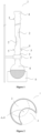
- FIG 1 illustrates an example of experimental setup comprising an air cooler 1 according to one embodiment of the invention, a tank 8, a heating mantle 9 and a support provided with a clamp 7 which supports the air cooler 1 by its end lower.
- a product such as a solvent, is (grayed area on the figure 1 ) heated in flask 8 until its boiling temperature. The product will then evaporate and the vapors will rise inside the air cooler 1. They will then come into contact with at least one fin 2, on which they will condense and liquefy. The droplets thus formed can then fall back into the balloon 8.
- the fins 2 extend from the general tubular shape towards the inside of the general tubular shape. Seen from the outside of the air cooler 1, the fins 2 for example only form recesses in the surface of the generally tubular shape.
- the air cooler 1 comprises two fins 2 which for example form essentially spherical invaginations of the wall towards the interior of the cooler 1 and which extend beyond the central longitudinal axis AA' (shown schematically in figure 2 , 3 and 4 ) of the air cooler 1. It also includes at least one lug 5 on its exterior wall, positioned on at least one bead 6. The presence of at least one lug and/or at least one bead is optional.
- the upper end of air cooler 1 shown in the experimental setup of the figure 1 was machined in female conical ground 4, and the lower end in male conical ground 3.
- the presence of a ground at at least one end of an air cooler 1 according to the invention makes it possible to adapt it to other elements of an experimental setup, for example a tank 8, and is optional depending on the uses of the air coolant 1.
- the fins 2 are advantageously arranged so as to reduce as much as possible the rectilinear spaces inside the air cooler 1, through which the vapors could pass through the air cooler from one end to the other without encountering a fin.
- the fins of an air cooler according to the invention are arranged so that, when the cooler is viewed from above, all together they cover approximately at least 60%, approximately at least 70%, approximately at least 80% or approximately at least 90% of the surface of the tube section. More preferably, the fins 2 are arranged in the refrigerant according to the invention so that there is no rectilinear space inside. of the air cooler 1 through which the vapors could pass through the air cooler from one end to the other without encountering a fin.
- the fins 2 are distributed inside an air cooler 1 so as not to overlap.
- Two adjacent fins can have part of the edges of their wall in contact with each other.
- the walls of two adjacent fins do not come into contact with each other.
- the smallest distance which separates the walls of two adjacent fins is approximately at least one, approximately at least two, approximately at least three, approximately at least four, approximately at least five, approximately at least six, about at least seven, about at least eight, or about at least nine millimeters.
- the smallest distance which separates the walls of two adjacent fins is approximately one centimeter. More preferably, the smallest distance which separates the walls of two adjacent fins is approximately one and a half centimeters, preferably two centimeters.
- the smallest distance which separates the walls of two adjacent fins varies between different pairs of adjacent fins within the same air cooler.
- the distances which separate two adjacent fins 2 are essentially identical.
- the fins 2 are arranged helically along the air cooler 1, i. e. around the central longitudinal axis A-A'.
- the propeller pitch then comprises approximately two, approximately three, approximately four, approximately five, approximately six, approximately seven, approximately eight, approximately nine, or approximately ten blades 2.
- the air cooler 1 can have a size suitable for use on a benchtop, that is to say a few tens of centimeters in length for a diameter of a few centimeters.
- the air cooler according to the invention can have a much larger size to allow the vapors of large quantities of product (several liters) to be condensed, in particular to meet industrial needs.
- the length and/or height of the air cooler according to the invention may be adapted, independently of one another, according to a factor of 2, 3, 4, 5, 6, 7, 8, 9, 10, 15, 20 or more.
- the air cooler according to the invention can have a length of approximately 200 cm and a diameter of approximately 30 cm.
- FIG. 2 shows a top view of a cross section made at the middle of the height of a fin 2 of the air cooler 1.
- Another fin 2 located below, is shown by a line formed by dashes.
- the wall of the air cooler at other heights is symbolized by the dotted line.
- the central longitudinal axis AA' of the air cooler is shown in the center thereof.
- the rectilinear spaces inside the refrigerant through which the vapors could pass through the refrigerant from one end to the other without encountering a fin are limited to the spaces which, on the example of the figure 2 , are both inside the refrigerant 1 and outside the zones corresponding to the fins 2.
- the air cooler 1 comprises at least two fins 2, preferably placed at an angle of approximately 180° between two successive fins.
- the air cooler 1 comprises at least three fins 2, arranged in an essentially helical manner forming an angle of approximately 120° between two successive fins, that is to say with a pitch of propeller comprising approximately three blades.
- FIG. 3 shows a longitudinal section of the lower part of an air cooler 1 according to another embodiment of the invention, on which are shown three fins 2 positioned helically with an angle of approximately 120° between two successive fins.
- the central longitudinal axis AA' is shown, as well as a bead 6 and a lug 5.
- the air cooler according to the Figure 3 ends at its lower end with a conical male grounding 3.
- FIG 4 is a cross-sectional view along section BB' shown on the Figure 3 .
- the fins 2 arranged helically with three fins per propeller pitch cover a larger surface area than the fins arranged opposite each other as illustrated in figure 2 , that is to say, they leave fewer rectilinear spaces through which vapors could escape without coming into contact with a fin.
- Three lugs 5 are shown, positioned on a bead 6.
- the air cooler 1 comprises a running-in at at least one of its ends.
- the air cooler 1 comprises a male conical grounding 3 at the lower end intended to be placed downwards in the experimental setup, for example to interoperate with a balloon, and/or a female conical grounding 4 at its upper end.
- the male conical grounding is located at the upper end and the female conical grounding at the lower end of an air cooler according to the invention.
- the air cooler according to the invention has a male connection at each of its ends, or alternatively a female connection at each of its ends.
- a conical lapping in the context of the invention is also called a conical connection or standardized cone.
- Known standardized cones are for example CN 14/23, 19/26, 24/29, 29/32, 34/35, 40/38, 45/40, 50/42, 55/44, 60/46, 70 /50, 85/55, 100/60, male or female, in particular the male cone CNM 29/32 or the female cone CNF 19/26, the numbers giving the indication of their opening dimensions.
- the air cooler 1 according to the invention comprises at least one lug 5 allowing its stabilization.
- a lug for an air cooler according to the invention corresponds to a protuberance located on the outside of the wall of the air cooler, which prevents the air cooler from rotating several times along its central longitudinal axis A-A' when It is placed on a horizontal support, such as a table or a bench for example.
- a lug according to the invention can take different shapes, for example essentially spherical or essentially cubic.
- the lugs 5 are located on an enlarged part of the tube which forms a bead 6.
- at least one, at least two, at least three, at least four or at least five lugs are present on the wall of an air cooler 1.
- the air cooler 1 is made of thermoplastic material comprising glass, a material which is suitable for use involving vapor flows, in other words which offers good resistance to the temperature and humidity conditions generated by the evaporation of 'a product.
- the thermoplastic material is glass.
- the type of glass suitable for an air cooler according to the invention comprises any type of glass conventionally used to manufacture laboratory glassware.
- the glass can be chosen from ordinary white glass, soda lime glass, borosilicate glass consisting essentially of boron and silica, or brown glass.
- an air cooler according to the invention is made of thermoplastic composite material, such as for example the fiberglass and thermoplastic polymer materials described in the patent EP1734076B1 .
- the fins 2 are made of the same material as the wall of the air cooler 1, preferably glass. According to another embodiment, the fins 2 are formed in a material different from that of the wall of the air cooler 1.
- a device according to the invention comprising the air cooler 1, a tank 8 and a heater tank 9.
- the device further comprises a support provided with a clamp 7.
- the balloons 8 and heating mantles 9 are chosen according to the desired experiment and their compatibility. These products are well known and described in many catalogs of laboratory product suppliers. According to this object, the dimensions of the air coolant 1 can be modulated so as to allow it to interoperate with the tank 8, for example by adapting the diameter of the coolant to that of the neck of the tank, for example by welding a running-in conical at the lower end of the refrigerant.
- a process for manufacturing the air refrigerant 1 is also described.
- the heated zone is deformed by applying a vacuum inside the tube made of thermoplastic material, for example by sucking with the mouth at one of the ends of said tube.
- the fins 2 are made by suction to the mouth at one end of the tube and form half-spheres also called “suction balls”.
- the fins 2 are arranged helically along the tube, for example with at least two, at least three or at least four fins per propeller pitch.
- a fin in the context of the invention, can have an essentially planar general shape (for example a furrow), essentially cylindrical, or essentially spherical, more particularly essentially the shape of a half-sphere.
- the method of manufacturing a refrigerant according to the invention further comprises the welding of a conical rod at at least one end.
- the running-in can be carried out by any means known to those skilled in the art. For example, it can be made by a numerically controlled machine, or by a glass blower.
- the manufacture of the lapping is usually carried out in two stages, including a first hot shaping stage, during which the lapping has a translucent appearance, and a second so-called lapping stage, during which the glass is worn by hand by the successive use of carborundum or silica carbide abrasives whose grain size decreases successively, or automatically using diamond tools.
- Conventional lappings are available commercially.
- the lapping can be welded to the tube before or after the fins are formed, preferably before.
- the method of manufacturing an air cooler according to the invention further comprises the addition of at least one lug outside the cooler.
- the additional step of adding a lug can be carried out by any means known to those skilled in the art.
- a lug can be made of glass and made by melting one end of a glass rod so as to deposit on the exterior wall of the air cooler a drop of glass which will harden as it cools.
- the air cooler 1 is for example used to cool a vapor or a mixture of vapors circulating inside the air cooler by heat exchange with ambient air outside the air cooler.
- ambient air is for example ordinary (atmospheric) air, or a inert gas, the air refrigerant 1 then being located in a hood (not shown).
- the ambient air enters the housings formed by each of the fins 2.
- a heat exchange occurs between the vapor(s) and the ambient air via the thermoplastic material.
- the fins 2 advantageously have the effect of increasing the contact surface between the vapor(s) and the thermoplastic material cooled by the ambient air.
- Cooling continues advantageously until one or more of said vapors condense.
- a 29/32 male cone type grounding was welded to a 28 mm diameter glass tube with a wall thickness of 2 mm.
- a bead was made 25 mm away from the male grounding, by heating the glass tube to the corresponding distance and blowing inside the tube.
- a 19/26 female cone type grounding was welded to the desired final length of the air cooler, here 500mm.
- a first rounded lug was welded to the bead using the glass rod, then a second lug was welded to the bead at 120° of the first, and finally a third lug was welded to the bead at 120° of the first two .
- the lugs were used as marks to align the fins which were subsequently produced.
- the first fin was made 25 mm from the bead by gently heating, that is to say with a soft or stiff flame, the tube in the corresponding zone and by sucking into the mouth at one of the ends of the tube, from so as to obtain a fin in the shape of a suction ball which extends towards the interior of the refrigerant beyond the central longitudinal axis AA' of the tube.
- the diameter at the base of the fin was approximately 25 mm.
- the second suction ball fin was made in the same way, taking the next lug as a reference, and placing it 25 mm from the first fin, in the direction of the female lapping. In this way, the vertices of the first and the second fin were spaced at a height of approximately 25 mm.
- the following fins were made by repeating these steps until the desired length.
- the inventors produced an air refrigerant according to the method described above and compared the performances of said air refrigerant to those of other commercially available refrigerants.
- a volume of 150 mL of solvent was placed in a 150 mL flask and heated to reflux using a DrySyn ® reaction block for 6 or 16 hours.
- the room temperature was constant and equal to 20°C.
- the seal between the refrigerant and the tank was achieved by a Teflon ® seal.
- Table 1 presents, for the four solvents tested, their density and their boiling temperature (Teb). This table also reports the temperature experimental (Texp) applied to solvents and the heating time (exp. time). Finally, Table 1 presents the results obtained in percentages of total product loss. It appears from these data that the air refrigerant according to the invention has an efficiency at least equivalent to that of a coil refrigerant, which is a water refrigerant. For example, the results are comparable for ether and toluene.
- the air coolant according to the invention is approximately twice as effective as the water coolant for the solvents dichloromethane and acetonitrile, regardless of the duration of the experiment.
- a second experiment consisted of introducing 150 mL of solvent heated to reflux into a 150 mL flask for 8 hours. Heating was carried out using a DrySyn ® reaction block. The heating temperature was 5 to 20°C above the boiling temperature of the solvent. The seal between the refrigerant and the tank was achieved by a Teflon ® seal. The ambient temperature measured in the room was constant and 20°C.
Landscapes
- Engineering & Computer Science (AREA)
- Physics & Mathematics (AREA)
- Thermal Sciences (AREA)
- Mechanical Engineering (AREA)
- General Engineering & Computer Science (AREA)
- Chemical & Material Sciences (AREA)
- Chemical Kinetics & Catalysis (AREA)
- Geometry (AREA)
- Heat-Exchange Devices With Radiators And Conduit Assemblies (AREA)
- Devices For Use In Laboratory Experiments (AREA)
Claims (13)
- Luftkühler (1) mit allgemein röhrenförmiger Form, der eine mittlere Längsachse (A-A') definiert, wobei der Luftkühler (1) aus einem thermoplastischen Material besteht, das Glas umfasst, dadurch gekennzeichnet, dass der Luftkühler (1) mindestens zwei Rippen (2) umfasst, die zur Innenseite des Luftkühlers (1) gerichtet sind, wobei sich die Rippen (2) über die mittlere Längsachse (A-A') hinaus erstrecken.
- Luftkühler (1) nach Anspruch 1, dadurch gekennzeichnet, dass er aus Glas besteht.
- Luftkühler (1) nach Anspruch 1 oder 2, wobei die mittlere Längsachse (A-A') eine Drehachse der allgemein röhrenförmigen Form ist.
- Luftkühlmittel (1) nach einem der vorherigen Ansprüche, ferner umfassend mindestens einen Stift (5).
- Luftkühler (1) nach einem der vorherigen Ansprüche, ferner umfassend ein Läppen an einem oberen Ende (4) entlang der mittleren Längsachse (A-A') und/oder ein Läppen an einem unteren Ende (3) entlang der mittleren Längsachse (A-A').
- Luftkühler (1) nach einem der Ansprüche 1 bis 5, wobei die Rippen (2) spiralförmig entlang des Luftkühlers (1) angeordnet sind.
- Luftkühler (1) nach einem der Ansprüche 1 bis 6, wobei die Innenseite und der Umfang des Luftkühlers (1) frei von jeglichen zusätzlichen Kreisläufen sind, die für den Umlauf einer Kühlflüssigkeit bestimmt sind.
- Vorrichtung, umfassend einen Luftkühler (1) nach einem der vorherigen Ansprüche, einen Ballon (8) und einen Ballonwärmer (9).
- Verfahren zur Herstellung eines Luftkühlers (1) nach einem der Ansprüche 1 bis 7, umfassend die folgenden Schritte:i) Erwärmen eines zu verformenden Bereichs eines Rohrs aus thermoplastischem Material,ii) Verformen des erwärmten Bereichs, um eine Rippe (2) zu erzeugen, die in die Innenseite des Rohrs gerichtet ist und sich über die mittlere Längsachse (A-A') hinaus erstreckt, wobei Schritt ii) durch Erzeugen eines Unterdrucks in dem Rohr durchgeführt wird, undiii) Wiederholen von Schritt i) und ii), bis eine gewünschte Anzahl von Rippen (2) erreicht ist.
- Verfahren nach Anspruch 9, wobei Schritt ii) durchgeführt wird, indem ein Ende des Rohrs angesaugt wird, um den Rippen (2) aus einer angesaugten Kugel zu erzeugen.
- Verwendung eines Luftkühlers (1) nach einem der Ansprüche 1 bis 7 oder einer Vorrichtung nach Anspruch 8, wobei mindestens ein innerhalb des Luftkühlers (1) zirkulierender Dampf durch Wärmeaustausch mit einer außerhalb des Luftkühlers (1) befindlichen Umgebungsluft gekühlt wird.
- Verwendung nach Anspruch 11, wobei der abgekühlte Dampf kondensiert.
- Verwendung nach Anspruch 11 oder 12, wobei die Umgebungsluft wie folgt ist:- atmosphärische Luft oder- ein Inertgas, wobei sich der Luftkühler (1) dann in einer Haube befindet.
Applications Claiming Priority (1)
| Application Number | Priority Date | Filing Date | Title |
|---|---|---|---|
| FR1870631A FR3081979B1 (fr) | 2018-05-31 | 2018-05-31 | Refrigerant a air |
Publications (2)
| Publication Number | Publication Date |
|---|---|
| EP3575729A1 EP3575729A1 (de) | 2019-12-04 |
| EP3575729B1 true EP3575729B1 (de) | 2023-11-29 |
Family
ID=63491816
Family Applications (1)
| Application Number | Title | Priority Date | Filing Date |
|---|---|---|---|
| EP19177575.8A Active EP3575729B1 (de) | 2018-05-31 | 2019-05-31 | Luftkühler |
Country Status (2)
| Country | Link |
|---|---|
| EP (1) | EP3575729B1 (de) |
| FR (1) | FR3081979B1 (de) |
Families Citing this family (1)
| Publication number | Priority date | Publication date | Assignee | Title |
|---|---|---|---|---|
| CN110975962B (zh) * | 2019-12-31 | 2021-07-23 | 中国人民解放军陆军军医大学第一附属医院 | 一种电热恒温水浴箱 |
Citations (2)
| Publication number | Priority date | Publication date | Assignee | Title |
|---|---|---|---|---|
| CA2693509C (en) * | 2009-03-05 | 2012-07-10 | Yutaka Giken Co., Ltd. | Heat exchange tube |
| US20130325361A1 (en) * | 2012-06-01 | 2013-12-05 | Nanjing University | Device and method for evaluating scale inhibitor |
Family Cites Families (4)
| Publication number | Priority date | Publication date | Assignee | Title |
|---|---|---|---|---|
| GB811722A (en) * | 1954-08-06 | 1959-04-08 | Sulzer Ag | Fluid separator tubes |
| US4333523A (en) * | 1979-11-01 | 1982-06-08 | Miles Laboratories, Inc. | Reflux condenser |
| US20060287429A1 (en) | 2005-06-17 | 2006-12-21 | Gaggar Satish K | Glass fiber thermoplastic composite |
| PL232219B1 (pl) * | 2015-07-05 | 2019-05-31 | Aic Spolka Akcyjna | Rura płomienna kondensacyjnego wymiennika ciepła |
-
2018
- 2018-05-31 FR FR1870631A patent/FR3081979B1/fr active Active
-
2019
- 2019-05-31 EP EP19177575.8A patent/EP3575729B1/de active Active
Patent Citations (2)
| Publication number | Priority date | Publication date | Assignee | Title |
|---|---|---|---|---|
| CA2693509C (en) * | 2009-03-05 | 2012-07-10 | Yutaka Giken Co., Ltd. | Heat exchange tube |
| US20130325361A1 (en) * | 2012-06-01 | 2013-12-05 | Nanjing University | Device and method for evaluating scale inhibitor |
Also Published As
| Publication number | Publication date |
|---|---|
| FR3081979B1 (fr) | 2020-07-03 |
| FR3081979A1 (fr) | 2019-12-06 |
| EP3575729A1 (de) | 2019-12-04 |
Similar Documents
| Publication | Publication Date | Title |
|---|---|---|
| KR102768655B1 (ko) | 하이브리드 리프트 핀 | |
| CN212205767U (zh) | 均温板 | |
| EP0678186B1 (de) | Wärmetauschelement, verfahren und vorrichtung zu dessen herstellung | |
| EP3575729B1 (de) | Luftkühler | |
| FR2591799A1 (fr) | Tube a double paroi en verre de silice pour l'execution de processus de la technologie des semi-conducteurs | |
| WO2008119900A2 (fr) | Procede de fabrication d'un dispositif de type echangeur de chaleur en ceramique et dispositifs obtenus par le procede | |
| US20060197245A1 (en) | Method of manufacturing heat pipe having sintered powder wick | |
| US20100126701A1 (en) | Plate-type heat pipe and method for manufacturing the same | |
| FR2928449A1 (fr) | Dispositif d'echange de chaleur et procede de fabrication d'un element d'echange de chaleur pour un dispositif d'echange de chaleur | |
| FR2490801A1 (fr) | Elements transmetteurs de chaleur pour echange thermique par regeneration | |
| WO2018019865A1 (fr) | Echangeur de chaleur a tubes verticaux et procede d'echange de chaleur | |
| WO2012168352A1 (fr) | Reacteur solide / gaz caloporteur et reactif comprenant un conduit helicoïdal dans lequel le solide et le gaz circulent a contre-courant | |
| FR2847759A1 (fr) | Systeme de chauffage | |
| FR2963024A1 (fr) | Reacteur de depot chimique en phase gazeuse ameliore | |
| CN102719810A (zh) | 薄膜沉积系统 | |
| WO2011104479A1 (fr) | Panneau solaire thermique a rendement eleve | |
| WO2012049433A1 (fr) | Procede de bombage et support de trempe thermique | |
| WO2017212148A1 (fr) | Dispositif cryogenique a echangeur compact | |
| FR2953919A1 (fr) | Echangeur de chaleur en aluminium brase | |
| EP0588733B1 (de) | Flüssiggas Kontaktapparat des fallenden Filmtyps | |
| TW201908253A (zh) | 層疊型石英及層疊型石英製造方法 | |
| CN109244803A (zh) | 一种管状激光增益介质及其封装方法 | |
| EP3529549B1 (de) | Eisbasierte thermische energiespeichervorrichtung | |
| EP3194874B1 (de) | Wärmerohr und verfahren zur herstellung eines wärmerohrs | |
| FR2866872A1 (fr) | Plaque vitroceramique et son procede de fabrication |
Legal Events
| Date | Code | Title | Description |
|---|---|---|---|
| PUAI | Public reference made under article 153(3) epc to a published international application that has entered the european phase |
Free format text: ORIGINAL CODE: 0009012 |
|
| STAA | Information on the status of an ep patent application or granted ep patent |
Free format text: STATUS: THE APPLICATION HAS BEEN PUBLISHED |
|
| AK | Designated contracting states |
Kind code of ref document: A1 Designated state(s): AL AT BE BG CH CY CZ DE DK EE ES FI FR GB GR HR HU IE IS IT LI LT LU LV MC MK MT NL NO PL PT RO RS SE SI SK SM TR |
|
| AX | Request for extension of the european patent |
Extension state: BA ME |
|
| STAA | Information on the status of an ep patent application or granted ep patent |
Free format text: STATUS: REQUEST FOR EXAMINATION WAS MADE |
|
| 17P | Request for examination filed |
Effective date: 20200505 |
|
| RBV | Designated contracting states (corrected) |
Designated state(s): AL AT BE BG CH CY CZ DE DK EE ES FI FR GB GR HR HU IE IS IT LI LT LU LV MC MK MT NL NO PL PT RO RS SE SI SK SM TR |
|
| STAA | Information on the status of an ep patent application or granted ep patent |
Free format text: STATUS: EXAMINATION IS IN PROGRESS |
|
| 17Q | First examination report despatched |
Effective date: 20200622 |
|
| GRAP | Despatch of communication of intention to grant a patent |
Free format text: ORIGINAL CODE: EPIDOSNIGR1 |
|
| STAA | Information on the status of an ep patent application or granted ep patent |
Free format text: STATUS: GRANT OF PATENT IS INTENDED |
|
| INTG | Intention to grant announced |
Effective date: 20230224 |
|
| GRAJ | Information related to disapproval of communication of intention to grant by the applicant or resumption of examination proceedings by the epo deleted |
Free format text: ORIGINAL CODE: EPIDOSDIGR1 |
|
| STAA | Information on the status of an ep patent application or granted ep patent |
Free format text: STATUS: EXAMINATION IS IN PROGRESS |
|
| RAP1 | Party data changed (applicant data changed or rights of an application transferred) |
Owner name: CENTRE NATIONAL DE LA RECHERCHE SCIENTIFIQUE Owner name: UNIVERSITE DE RENNES |
|
| INTC | Intention to grant announced (deleted) | ||
| P01 | Opt-out of the competence of the unified patent court (upc) registered |
Effective date: 20230527 |
|
| GRAP | Despatch of communication of intention to grant a patent |
Free format text: ORIGINAL CODE: EPIDOSNIGR1 |
|
| STAA | Information on the status of an ep patent application or granted ep patent |
Free format text: STATUS: GRANT OF PATENT IS INTENDED |
|
| INTG | Intention to grant announced |
Effective date: 20230714 |
|
| RIC1 | Information provided on ipc code assigned before grant |
Ipc: A61F 2/68 20060101ALN20230630BHEP Ipc: F28F 1/42 20060101AFI20230630BHEP |
|
| GRAS | Grant fee paid |
Free format text: ORIGINAL CODE: EPIDOSNIGR3 |
|
| GRAA | (expected) grant |
Free format text: ORIGINAL CODE: 0009210 |
|
| STAA | Information on the status of an ep patent application or granted ep patent |
Free format text: STATUS: THE PATENT HAS BEEN GRANTED |
|
| AK | Designated contracting states |
Kind code of ref document: B1 Designated state(s): AL AT BE BG CH CY CZ DE DK EE ES FI FR GB GR HR HU IE IS IT LI LT LU LV MC MK MT NL NO PL PT RO RS SE SI SK SM TR |
|
| REG | Reference to a national code |
Ref country code: GB Ref legal event code: FG4D Free format text: NOT ENGLISH |
|
| REG | Reference to a national code |
Ref country code: CH Ref legal event code: EP |
|
| REG | Reference to a national code |
Ref country code: DE Ref legal event code: R096 Ref document number: 602019042207 Country of ref document: DE |
|
| REG | Reference to a national code |
Ref country code: IE Ref legal event code: FG4D Free format text: LANGUAGE OF EP DOCUMENT: FRENCH |
|
| REG | Reference to a national code |
Ref country code: LT Ref legal event code: MG9D |
|
| REG | Reference to a national code |
Ref country code: NL Ref legal event code: MP Effective date: 20231129 |
|
| PG25 | Lapsed in a contracting state [announced via postgrant information from national office to epo] |
Ref country code: GR Free format text: LAPSE BECAUSE OF FAILURE TO SUBMIT A TRANSLATION OF THE DESCRIPTION OR TO PAY THE FEE WITHIN THE PRESCRIBED TIME-LIMIT Effective date: 20240301 |
|
| PG25 | Lapsed in a contracting state [announced via postgrant information from national office to epo] |
Ref country code: IS Free format text: LAPSE BECAUSE OF FAILURE TO SUBMIT A TRANSLATION OF THE DESCRIPTION OR TO PAY THE FEE WITHIN THE PRESCRIBED TIME-LIMIT Effective date: 20240329 |
|
| PG25 | Lapsed in a contracting state [announced via postgrant information from national office to epo] |
Ref country code: LT Free format text: LAPSE BECAUSE OF FAILURE TO SUBMIT A TRANSLATION OF THE DESCRIPTION OR TO PAY THE FEE WITHIN THE PRESCRIBED TIME-LIMIT Effective date: 20231129 |
|
| PG25 | Lapsed in a contracting state [announced via postgrant information from national office to epo] |
Ref country code: ES Free format text: LAPSE BECAUSE OF FAILURE TO SUBMIT A TRANSLATION OF THE DESCRIPTION OR TO PAY THE FEE WITHIN THE PRESCRIBED TIME-LIMIT Effective date: 20231129 |
|
| PG25 | Lapsed in a contracting state [announced via postgrant information from national office to epo] |
Ref country code: LT Free format text: LAPSE BECAUSE OF FAILURE TO SUBMIT A TRANSLATION OF THE DESCRIPTION OR TO PAY THE FEE WITHIN THE PRESCRIBED TIME-LIMIT Effective date: 20231129 Ref country code: IS Free format text: LAPSE BECAUSE OF FAILURE TO SUBMIT A TRANSLATION OF THE DESCRIPTION OR TO PAY THE FEE WITHIN THE PRESCRIBED TIME-LIMIT Effective date: 20240329 Ref country code: GR Free format text: LAPSE BECAUSE OF FAILURE TO SUBMIT A TRANSLATION OF THE DESCRIPTION OR TO PAY THE FEE WITHIN THE PRESCRIBED TIME-LIMIT Effective date: 20240301 Ref country code: ES Free format text: LAPSE BECAUSE OF FAILURE TO SUBMIT A TRANSLATION OF THE DESCRIPTION OR TO PAY THE FEE WITHIN THE PRESCRIBED TIME-LIMIT Effective date: 20231129 Ref country code: BG Free format text: LAPSE BECAUSE OF FAILURE TO SUBMIT A TRANSLATION OF THE DESCRIPTION OR TO PAY THE FEE WITHIN THE PRESCRIBED TIME-LIMIT Effective date: 20240229 |
|
| REG | Reference to a national code |
Ref country code: AT Ref legal event code: MK05 Ref document number: 1636531 Country of ref document: AT Kind code of ref document: T Effective date: 20231129 |
|
| PG25 | Lapsed in a contracting state [announced via postgrant information from national office to epo] |
Ref country code: NL Free format text: LAPSE BECAUSE OF FAILURE TO SUBMIT A TRANSLATION OF THE DESCRIPTION OR TO PAY THE FEE WITHIN THE PRESCRIBED TIME-LIMIT Effective date: 20231129 |
|
| PG25 | Lapsed in a contracting state [announced via postgrant information from national office to epo] |
Ref country code: SE Free format text: LAPSE BECAUSE OF FAILURE TO SUBMIT A TRANSLATION OF THE DESCRIPTION OR TO PAY THE FEE WITHIN THE PRESCRIBED TIME-LIMIT Effective date: 20231129 Ref country code: RS Free format text: LAPSE BECAUSE OF FAILURE TO SUBMIT A TRANSLATION OF THE DESCRIPTION OR TO PAY THE FEE WITHIN THE PRESCRIBED TIME-LIMIT Effective date: 20231129 Ref country code: PL Free format text: LAPSE BECAUSE OF FAILURE TO SUBMIT A TRANSLATION OF THE DESCRIPTION OR TO PAY THE FEE WITHIN THE PRESCRIBED TIME-LIMIT Effective date: 20231129 Ref country code: NO Free format text: LAPSE BECAUSE OF FAILURE TO SUBMIT A TRANSLATION OF THE DESCRIPTION OR TO PAY THE FEE WITHIN THE PRESCRIBED TIME-LIMIT Effective date: 20240229 Ref country code: NL Free format text: LAPSE BECAUSE OF FAILURE TO SUBMIT A TRANSLATION OF THE DESCRIPTION OR TO PAY THE FEE WITHIN THE PRESCRIBED TIME-LIMIT Effective date: 20231129 Ref country code: LV Free format text: LAPSE BECAUSE OF FAILURE TO SUBMIT A TRANSLATION OF THE DESCRIPTION OR TO PAY THE FEE WITHIN THE PRESCRIBED TIME-LIMIT Effective date: 20231129 Ref country code: HR Free format text: LAPSE BECAUSE OF FAILURE TO SUBMIT A TRANSLATION OF THE DESCRIPTION OR TO PAY THE FEE WITHIN THE PRESCRIBED TIME-LIMIT Effective date: 20231129 |
|
| PG25 | Lapsed in a contracting state [announced via postgrant information from national office to epo] |
Ref country code: DK Free format text: LAPSE BECAUSE OF FAILURE TO SUBMIT A TRANSLATION OF THE DESCRIPTION OR TO PAY THE FEE WITHIN THE PRESCRIBED TIME-LIMIT Effective date: 20231129 |
|
| PG25 | Lapsed in a contracting state [announced via postgrant information from national office to epo] |
Ref country code: AT Free format text: LAPSE BECAUSE OF FAILURE TO SUBMIT A TRANSLATION OF THE DESCRIPTION OR TO PAY THE FEE WITHIN THE PRESCRIBED TIME-LIMIT Effective date: 20231129 |
|
| PG25 | Lapsed in a contracting state [announced via postgrant information from national office to epo] |
Ref country code: SK Free format text: LAPSE BECAUSE OF FAILURE TO SUBMIT A TRANSLATION OF THE DESCRIPTION OR TO PAY THE FEE WITHIN THE PRESCRIBED TIME-LIMIT Effective date: 20231129 |
|
| PG25 | Lapsed in a contracting state [announced via postgrant information from national office to epo] |
Ref country code: SM Free format text: LAPSE BECAUSE OF FAILURE TO SUBMIT A TRANSLATION OF THE DESCRIPTION OR TO PAY THE FEE WITHIN THE PRESCRIBED TIME-LIMIT Effective date: 20231129 Ref country code: SK Free format text: LAPSE BECAUSE OF FAILURE TO SUBMIT A TRANSLATION OF THE DESCRIPTION OR TO PAY THE FEE WITHIN THE PRESCRIBED TIME-LIMIT Effective date: 20231129 Ref country code: RO Free format text: LAPSE BECAUSE OF FAILURE TO SUBMIT A TRANSLATION OF THE DESCRIPTION OR TO PAY THE FEE WITHIN THE PRESCRIBED TIME-LIMIT Effective date: 20231129 Ref country code: IT Free format text: LAPSE BECAUSE OF FAILURE TO SUBMIT A TRANSLATION OF THE DESCRIPTION OR TO PAY THE FEE WITHIN THE PRESCRIBED TIME-LIMIT Effective date: 20231129 Ref country code: EE Free format text: LAPSE BECAUSE OF FAILURE TO SUBMIT A TRANSLATION OF THE DESCRIPTION OR TO PAY THE FEE WITHIN THE PRESCRIBED TIME-LIMIT Effective date: 20231129 Ref country code: DK Free format text: LAPSE BECAUSE OF FAILURE TO SUBMIT A TRANSLATION OF THE DESCRIPTION OR TO PAY THE FEE WITHIN THE PRESCRIBED TIME-LIMIT Effective date: 20231129 Ref country code: AT Free format text: LAPSE BECAUSE OF FAILURE TO SUBMIT A TRANSLATION OF THE DESCRIPTION OR TO PAY THE FEE WITHIN THE PRESCRIBED TIME-LIMIT Effective date: 20231129 |
|
| PG25 | Lapsed in a contracting state [announced via postgrant information from national office to epo] |
Ref country code: PT Free format text: LAPSE BECAUSE OF FAILURE TO SUBMIT A TRANSLATION OF THE DESCRIPTION OR TO PAY THE FEE WITHIN THE PRESCRIBED TIME-LIMIT Effective date: 20240401 |
|
| PG25 | Lapsed in a contracting state [announced via postgrant information from national office to epo] |
Ref country code: PT Free format text: LAPSE BECAUSE OF FAILURE TO SUBMIT A TRANSLATION OF THE DESCRIPTION OR TO PAY THE FEE WITHIN THE PRESCRIBED TIME-LIMIT Effective date: 20240401 |
|
| REG | Reference to a national code |
Ref country code: DE Ref legal event code: R097 Ref document number: 602019042207 Country of ref document: DE |
|
| PLBE | No opposition filed within time limit |
Free format text: ORIGINAL CODE: 0009261 |
|
| STAA | Information on the status of an ep patent application or granted ep patent |
Free format text: STATUS: NO OPPOSITION FILED WITHIN TIME LIMIT |
|
| PG25 | Lapsed in a contracting state [announced via postgrant information from national office to epo] |
Ref country code: SI Free format text: LAPSE BECAUSE OF FAILURE TO SUBMIT A TRANSLATION OF THE DESCRIPTION OR TO PAY THE FEE WITHIN THE PRESCRIBED TIME-LIMIT Effective date: 20231129 |
|
| PG25 | Lapsed in a contracting state [announced via postgrant information from national office to epo] |
Ref country code: SI Free format text: LAPSE BECAUSE OF FAILURE TO SUBMIT A TRANSLATION OF THE DESCRIPTION OR TO PAY THE FEE WITHIN THE PRESCRIBED TIME-LIMIT Effective date: 20231129 |
|
| 26N | No opposition filed |
Effective date: 20240830 |
|
| REG | Reference to a national code |
Ref country code: CH Ref legal event code: PL |
|
| PG25 | Lapsed in a contracting state [announced via postgrant information from national office to epo] |
Ref country code: MC Free format text: LAPSE BECAUSE OF FAILURE TO SUBMIT A TRANSLATION OF THE DESCRIPTION OR TO PAY THE FEE WITHIN THE PRESCRIBED TIME-LIMIT Effective date: 20231129 |
|
| PG25 | Lapsed in a contracting state [announced via postgrant information from national office to epo] |
Ref country code: MC Free format text: LAPSE BECAUSE OF FAILURE TO SUBMIT A TRANSLATION OF THE DESCRIPTION OR TO PAY THE FEE WITHIN THE PRESCRIBED TIME-LIMIT Effective date: 20231129 Ref country code: CH Free format text: LAPSE BECAUSE OF NON-PAYMENT OF DUE FEES Effective date: 20240531 |
|
| PG25 | Lapsed in a contracting state [announced via postgrant information from national office to epo] |
Ref country code: IE Free format text: LAPSE BECAUSE OF NON-PAYMENT OF DUE FEES Effective date: 20240531 |
|
| PG25 | Lapsed in a contracting state [announced via postgrant information from national office to epo] |
Ref country code: FR Free format text: LAPSE BECAUSE OF NON-PAYMENT OF DUE FEES Effective date: 20240531 |
|
| PGFP | Annual fee paid to national office [announced via postgrant information from national office to epo] |
Ref country code: LU Payment date: 20250429 Year of fee payment: 7 |
|
| PGFP | Annual fee paid to national office [announced via postgrant information from national office to epo] |
Ref country code: DE Payment date: 20250513 Year of fee payment: 7 |
|
| PGFP | Annual fee paid to national office [announced via postgrant information from national office to epo] |
Ref country code: GB Payment date: 20250521 Year of fee payment: 7 |
|
| PGFP | Annual fee paid to national office [announced via postgrant information from national office to epo] |
Ref country code: BE Payment date: 20250527 Year of fee payment: 7 |
|
| PGFP | Annual fee paid to national office [announced via postgrant information from national office to epo] |
Ref country code: CZ Payment date: 20250526 Year of fee payment: 7 |
|
| PG25 | Lapsed in a contracting state [announced via postgrant information from national office to epo] |
Ref country code: CY Free format text: LAPSE BECAUSE OF FAILURE TO SUBMIT A TRANSLATION OF THE DESCRIPTION OR TO PAY THE FEE WITHIN THE PRESCRIBED TIME-LIMIT; INVALID AB INITIO Effective date: 20190531 |
|
| PG25 | Lapsed in a contracting state [announced via postgrant information from national office to epo] |
Ref country code: FI Free format text: LAPSE BECAUSE OF FAILURE TO SUBMIT A TRANSLATION OF THE DESCRIPTION OR TO PAY THE FEE WITHIN THE PRESCRIBED TIME-LIMIT Effective date: 20231129 |
|
| PG25 | Lapsed in a contracting state [announced via postgrant information from national office to epo] |
Ref country code: HU Free format text: LAPSE BECAUSE OF FAILURE TO SUBMIT A TRANSLATION OF THE DESCRIPTION OR TO PAY THE FEE WITHIN THE PRESCRIBED TIME-LIMIT; INVALID AB INITIO Effective date: 20190531 |