EP3575729A1 - Réfrigérant à air - Google Patents
Réfrigérant à air Download PDFInfo
- Publication number
- EP3575729A1 EP3575729A1 EP19177575.8A EP19177575A EP3575729A1 EP 3575729 A1 EP3575729 A1 EP 3575729A1 EP 19177575 A EP19177575 A EP 19177575A EP 3575729 A1 EP3575729 A1 EP 3575729A1
- Authority
- EP
- European Patent Office
- Prior art keywords
- air cooler
- air
- fins
- refrigerant
- tube
- Prior art date
- Legal status (The legal status is an assumption and is not a legal conclusion. Google has not performed a legal analysis and makes no representation as to the accuracy of the status listed.)
- Granted
Links
Images

Classifications
-
- F—MECHANICAL ENGINEERING; LIGHTING; HEATING; WEAPONS; BLASTING
- F28—HEAT EXCHANGE IN GENERAL
- F28F—DETAILS OF HEAT-EXCHANGE AND HEAT-TRANSFER APPARATUS, OF GENERAL APPLICATION
- F28F1/00—Tubular elements; Assemblies of tubular elements
- F28F1/10—Tubular elements and assemblies thereof with means for increasing heat-transfer area, e.g. with fins, with projections, with recesses
- F28F1/42—Tubular elements and assemblies thereof with means for increasing heat-transfer area, e.g. with fins, with projections, with recesses the means being both outside and inside the tubular element
- F28F1/424—Means comprising outside portions integral with inside portions
- F28F1/426—Means comprising outside portions integral with inside portions the outside portions and the inside portions forming parts of complementary shape, e.g. concave and convex
-
- B—PERFORMING OPERATIONS; TRANSPORTING
- B01—PHYSICAL OR CHEMICAL PROCESSES OR APPARATUS IN GENERAL
- B01D—SEPARATION
- B01D3/00—Distillation or related exchange processes in which liquids are contacted with gaseous media, e.g. stripping
- B01D3/02—Distillation or related exchange processes in which liquids are contacted with gaseous media, e.g. stripping in boilers or stills
-
- B—PERFORMING OPERATIONS; TRANSPORTING
- B01—PHYSICAL OR CHEMICAL PROCESSES OR APPARATUS IN GENERAL
- B01D—SEPARATION
- B01D5/00—Condensation of vapours; Recovering volatile solvents by condensation
- B01D5/0003—Condensation of vapours; Recovering volatile solvents by condensation by using heat-exchange surfaces for indirect contact between gases or vapours and the cooling medium
- B01D5/0012—Vertical tubes
-
- F—MECHANICAL ENGINEERING; LIGHTING; HEATING; WEAPONS; BLASTING
- F28—HEAT EXCHANGE IN GENERAL
- F28F—DETAILS OF HEAT-EXCHANGE AND HEAT-TRANSFER APPARATUS, OF GENERAL APPLICATION
- F28F21/00—Constructions of heat-exchange apparatus characterised by the selection of particular materials
- F28F21/006—Constructions of heat-exchange apparatus characterised by the selection of particular materials of glass
-
- F—MECHANICAL ENGINEERING; LIGHTING; HEATING; WEAPONS; BLASTING
- F28—HEAT EXCHANGE IN GENERAL
- F28F—DETAILS OF HEAT-EXCHANGE AND HEAT-TRANSFER APPARATUS, OF GENERAL APPLICATION
- F28F21/00—Constructions of heat-exchange apparatus characterised by the selection of particular materials
- F28F21/06—Constructions of heat-exchange apparatus characterised by the selection of particular materials of plastics material
-
- B—PERFORMING OPERATIONS; TRANSPORTING
- B01—PHYSICAL OR CHEMICAL PROCESSES OR APPARATUS IN GENERAL
- B01L—CHEMICAL OR PHYSICAL LABORATORY APPARATUS FOR GENERAL USE
- B01L3/00—Containers or dishes for laboratory use, e.g. laboratory glassware; Droppers
- B01L3/08—Flasks
-
- B—PERFORMING OPERATIONS; TRANSPORTING
- B01—PHYSICAL OR CHEMICAL PROCESSES OR APPARATUS IN GENERAL
- B01L—CHEMICAL OR PHYSICAL LABORATORY APPARATUS FOR GENERAL USE
- B01L7/00—Heating or cooling apparatus; Heat insulating devices
Definitions
- the present invention relates to a cooling device, in particular an air-to-air laboratory refrigerant which is particularly suitable for use in an experimental assembly in a chemistry laboratory.
- Refrigerants or refrigerant tubes are objects frequently used in experimental setups, particularly in organic chemistry. They consist of a tube, typically glass, normally intended to be placed above a balloon in an experimental setup. When the product heated in the balloon turns into vapors, they go back into the refrigerant placed above. The role of the refrigerant is then to cool the product vapors so that the latter condense and fall back into the balloon. Thus, product loss is limited.
- refrigerants are water-based refrigerants which use a liquid that promotes the cooling of vapors, usually water, and are classified into three categories: straight, ball or serpentine, depending on the shape of the internal duct. of the device, through which will flow the vapor to be condensed or the water for cooling said vapor.
- the circulation of the liquid in the water coolers takes place either in a duct confined within the refrigerant, as is the case, for example, with coiled refrigerants or at the periphery of the refrigerant, for example the straight or at least one refrigerant. balls.
- refrigerants combining several of these forms, such as those illustrated for example in US4333523A .
- This circulation of liquid makes it possible to maintain a wall, intended to be in contact with the vapors, at a temperature lower than that of the vapors. When the vapors meet this cooler wall, they liquefy and flow, usually in the flask connected below the refrigerant. The colder the wall, the more vapor that liquefies instead of escaping system is important.
- water coolers are particularly effective because the circulation of a liquid makes it possible to continuously cool the wall in contact with the hot vapors.
- these refrigerants are at the origin of a significant water consumption.
- the connection to the water supply network becomes defective while it is not monitored, leakage or even flooding may occur.
- Another disadvantage is that the peripheral tank is not accessible for cleaning and it is common for seaweed to grow as the uses.
- air coolers which consist of a single straight tube in which the vapors circulate. There too, they will liquefy in contact with the wall of the tube whose temperature is lower than that of the vapors. It is then the ambient air that keeps the temperature of the tube wall below that of the steam.
- the ambient air temperature generally between 15 and 25 ° C, is higher than that of the circulating water coming from a cold water supply network (approximately 10 ° C), these straight tubes known from the state of the art are less effective than the water coolers described above, that is, they liquefy smaller amounts of vapors, which will then escape the refrigerant.
- Air coolers have been developed which have lateral enlargements intended to increase the surface of thermal exchanges with the ambient air. However, these refrigerants do not provide results comparable to those obtained with water coolers.
- the inventors have developed an air cooler which makes it possible to obtain a more effective condensation of vapors than the refrigerants of the prior art and which is freed from cooling by water. More particularly, the air cooler 1 according to the invention is provided with fins 2 which extend inwardly of the coolant, beyond a central longitudinal axis AA 'of the refrigerant.
- an object of the invention relates to an air cooler according to claim 1.
- the air cooler comprises the features corresponding to one or more of claims 2 to 7, taken singly or in any technically possible combination.
- a second object according to the invention relates to a device according to claim 8.
- a third object according to the invention relates to a manufacturing method according to claim 9.
- said method comprises the characteristics corresponding to claim 10.
- the invention finally relates to a use according to claim 11.
- the use comprises the features corresponding to one or more of claims 12 and 13, taken in isolation or in any technically possible combination.
- the present invention relates to an air cooler 1, in particular a laboratory air cooler, comprising at least two fins 2 extending inside the refrigerant beyond the central longitudinal axis A-A 'of said refrigerant.
- the term "about” is used to indicate that a value includes variations inherent in the margin of error related to the use of a measuring apparatus, the method used to determine the value or the method used to manufacture the refrigerant.
- the term "about”, placed in front of a value corresponds to plus or minus 10% of this value.
- air refrigerant denotes a device for cooling the vapor circulating inside said device, thanks to the temperature difference existing between the ambient air outside the device and said vapor.
- the ambient air is understood as any gas located around the device, for example air, or a particular gas such as an inert gas when the device is used in a box-type hood. gloves for example.
- an air cooler differs from a water cooler in that there is not provided at least one additional special circuit, at the periphery or inside the refrigerant, in which water will circulate or another liquid.
- the term "tube” serves to designate a shape that is essentially that of a cylinder of revolution.
- the term “tube” then designates the essentially cylindrical shape of the tube used for the manufacture of the refrigerant according to the invention before transformation, or the general form of a refrigerant manufactured according to the invention, without taking into account the hollows or bumps formed. by the fins, lapping, pins, beads, and / or other elements added by welding or deformation during the design of said refrigerant.
- the central longitudinal axis of the air cooler is for example an axis of revolution of the "tube".
- the axis of revolution of a cylinder of revolution is defined as the line passing through the centers of the bases of the cylinder of revolution, which is perpendicular to the bases.
- the term "lower end” of an air cooler according to the invention denotes the terminal portion of the refrigerant which, when it is positioned in a conventional experimental setup, is located downwards.
- the term "upper end” of an air cooler according to the invention denotes the terminal portion of the refrigerant which, when it is positioned in a conventional experimental setup, is upward.
- fuse means an extension towards the inside of the tube intended to increase the heat exchange surface between the inner and outer environments of said tube.
- an air cooler 1 having a substantially cylindrical or tubular shape and having at least two fins 2 which extend inwardly of the tube beyond the central longitudinal axis AA 'of said refrigerant 1.
- the air cooler 1 has a generally non-cylindrical tubular shape.
- the central longitudinal axis A-A ' is in the example represented an axis of revolution of the generally tubular shape.
- the general shape of the air cooler 1 is not of revolution about the central longitudinal axis A-A '.
- the general shape is square, elliptical, or oblong perpendicular to the central longitudinal axis A-A '.
- the air cooler 1 is intended to be used in an experimental setup, including in particular a balloon and a heating balloon.
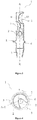
- the figure 1 illustrates an exemplary experimental setup comprising an air cooler 1 according to an embodiment of the invention, a balloon 8, a heater balloon 9 and a support provided with a clamp 7 which supports the air cooler 1 by its end lower.
- a product such as a solvent, is (gray area on the figure 1 ) heated in the flask 8 to its boiling point. The product will then evaporate and the vapors will go up inside the air cooler 1. They will then come into contact with at least one fin 2, on which they will condense and liquefy. The droplets thus formed can then fall back into the balloon 8.
- the fins 2 extend from the generally tubular shape inward to the generally tubular shape. Viewed from the outside of the air cooler 1, the fins 2 form for example only hollows in the surface of the generally tubular shape.
- the air cooler 1 comprises two fins 2 which form, for example, essentially spherical invaginations of the wall towards the inside of the cooler 1 and which extend beyond the central longitudinal axis AA '(shown schematically in FIG. figures 2 , 3 and 4 ) of the air cooler 1. It also comprises at least one lug 5 on its outer wall, positioned on at least one bead 6. The presence of at least one lug and / or at least one bead is optional.
- the upper end of the air cooler 1 illustrated in the experimental setup of the figure 1 has been machined in female conical lapping 4, and the lower end in male conical lapping 3.
- the presence of a lapping at least one end of an air cooler 1 according to the invention allows to adapt it to d ' other elements of an experimental setup, for example a balloon 8, and is optional depending on the uses of the air cooler 1.
- the fins 2 are advantageously arranged so as to reduce as much as possible the rectilinear spaces inside the air cooler 1, through which the vapors could pass through the air cooler from one end to the other without encountering a fin.
- the fins of an air cooler according to the invention are arranged so that, when the refrigerant is observed from above, all together they cover about at least 60%, at least about 70%, about minus 80% or at least 90% of the cross sectional area of the tube. More preferably, the fins 2 are arranged in the refrigerant according to the invention so that there is no rectilinear space inside. air cooler 1 through which the vapors could pass through the air cooler from one end to the other without encountering a fin.
- the fins 2 are distributed inside an air cooler 1 so as not to be superimposed.
- Two adjacent fins may have part of the edges of their wall in contact with each other.
- the walls of two adjacent fins do not come into contact with each other.
- the smallest distance separating the walls of two adjacent fins is at least about one, at least about two, at least about three, at least about four, about at least about five, about at least about six, about at least seven, at least about eight, or about at least nine millimeters.
- the smallest distance separating the walls of two adjacent fins is about one centimeter. More preferably, the smallest distance separating the walls of two adjacent fins is about one and a half centimeters, preferably two centimeters.
- the smallest distance separating the walls of two adjacent fins varies between different pairs of adjacent fins within the same air cooler.
- the distances separating two adjacent fins 2 are essentially identical.
- the fins 2 are helically arranged along the air cooler 1, i. e. around the central longitudinal axis A-A '.
- the pitch of the helix then comprises about two, about three, about four, about five, about six, about seven, about eight, about nine, or about ten fins 2.
- the air cooler 1 may have a size suitable for use on bench, that is to say a few tens of centimeters in length to a diameter of a few centimeters.
- the air refrigerant according to the invention may have a much larger size to allow the vapors to condense large quantities of product (several liters), in particular to meet industrial needs.
- the length and / or the height of the air refrigerant according to the invention can be adjusted, independently of one another, by a factor of 2, 3, 4, 5, 6, 7, 8, 9, 10, 15, 20 or more.
- the air refrigerant according to the invention may have a length of about 200 cm and a diameter of about 30 cm.
- the figure 2 shows a top view of a cross-section taken at the center of the height of a fin 2 of the air cooler 1.
- Another fin 2 located below is represented by a line formed by dashes.
- the wall of the air cooler at other heights is symbolized by the dashed line.
- the central longitudinal axis AA 'of the air cooler is represented in the center thereof.
- the rectilinear spaces inside the refrigerant through which the vapors could cross the refrigerant from one end to the other without meeting a fin are limited to the spaces which, on the example of the figure 2 , are both inside the refrigerant 1 and outside the zones corresponding to the fins 2.
- the air cooler 1 comprises at least two fins 2, preferably placed at an angle of about 180 ° between two successive fins.
- the air cooler 1 comprises at least three fins 2, arranged substantially helically at an angle of approximately 120 ° between two successive fins, that is to say with a pitch of helix comprising about three fins.
- the figure 3 shows a longitudinal section of the lower part of an air cooler 1 according to another embodiment of the invention, on which are represented three fins 2 helically positioned with an angle of about 120 ° between two successive fins.
- the central longitudinal axis AA ' is represented, as well as a bead 6 and a lug 5.
- the air cooler according to the figure 3 terminates at its lower end by a male taper.
- the figure 4 is a cross-sectional view along section BB 'shown in FIG. figure 3 .
- the fins 2 helically arranged with three fins per pitch cover a larger area than the fins arranged vis-à-vis as illustrated in FIG. figure 2 that is, they leave fewer straight spaces through which vapors could escape without coming into contact with a fin.
- Three pins 5 are shown, positioned on a bead 6.
- the air cooler 1 comprises a lapping at least one of its ends.
- the air refrigerant 1 comprises a male taper in the bottom end 3 to be placed down in the experimental assembly, for example to inter-operate with a balloon, and / or a female taper in its upper end.
- the male taper is in the upper end and the female taper in the lower end of an air cooler according to the invention.
- the air refrigerant according to the invention it is also possible for the air refrigerant according to the invention to have a male break-in at each of its ends, or alternatively a female break-in at each of its ends.
- a conical break-in in the context of the invention is also called conical connection or standardized cone.
- Known standardized cones are, for example, CN 14/23, 19/26, 24/29, 29/32, 34/35, 40/38, 45/40, 50/42, 55/44, 60/46, 70 / 50, 85/55, 100/60, male or female, in particular the CNM 29/32 male cone or the CNF 19/26 female cone, the numbers giving the indication of their opening dimensions.
- the air cooler 1 comprises at least one lug 5 for stabilizing it.
- a lug for air refrigerant according to the invention corresponds to a protuberance located on the outside of the wall of the air cooler, which makes it possible to prevent the air cooler from making several rotations along its central longitudinal axis AA 'when it is placed on a horizontal support, such as a table or a bench for example.
- a pin according to the invention can take different forms, for example essentially spherical or essentially cubic.
- the lugs 5 are located on an enlarged portion of the tube which forms a bead 6.
- at least one, at least two, at least three, at least four or at least five lugs are present on the wall of an air cooler 1.
- the air cooler 1 is made of a thermoplastic material comprising glass, a material which is suitable for use involving vapor streams, that is to say which offers good resistance to the temperature and humidity conditions generated by the evaporation of water. 'a product.
- the thermoplastic material is glass.
- the type of glass suitable for an air refrigerant according to the invention comprises any type of glass conventionally used to manufacture laboratory glassware.
- the glass may be selected from ordinary white glass, soda-lime glass, borosilicate glass consisting essentially of boron and silica, or brown glass.
- an air cooler according to the invention is made of a thermoplastic composite material, such as for example the fiberglass and thermoplastic polymer materials described in the patent. EP1734076B1 .
- the fins 2 are made of the same material as the wall of the air cooler 1, preferably glass. According to another embodiment, the fins 2 are formed in a material different from that of the wall of the air cooler 1.
- the device comprising the air cooler 1, a balloon 8 and a balloon heater 9.
- the device further comprises a support provided with a gripper 7.
- Balloons 8 and balloon heaters 9 are chosen according to the desired experimentation and their compatibility. These products are well known and described in numerous catalogs of suppliers of laboratory products. According to this object, the dimensions of the air cooler 1 can be modulated so as to allow it to inter-operate with the balloon 8, for example by adapting the diameter of the coolant to that of the neck of the balloon, for example by welding a break-in conical at the lower end of the refrigerant.
- a method of manufacturing the air cooler 1 is also described.
- the heated zone is deformed by the application of a vacuum inside the thermoplastic material tube, for example by sucking with the mouth at one end of said tube.
- the fins 2 are made by suction to the mouth at one end of the tube and form half-spheres also called "aspirated balls”.
- the fins 2 are helically arranged along the tube, for example with at least two, at least three or at least four fins per pitch of the helix.
- a fin may have a generally planar (for example a groove), essentially cylindrical, or essentially spherical shape, more particularly substantially in the shape of a hemisphere.
- the method of manufacturing a refrigerant according to the invention further comprises welding a taper in at least one end.
- Lapping can be achieved by any means known to those skilled in the art. For example, it can be done by a numerically controlled machine, or by a glass blower. Lapping is usually done in two stages, including a first hot forming step, during which the lapping has a translucent appearance, and a second so-called lapping step, during which the glass is worn by hand. by the successive use of carborundum or silica carbide abrasives whose grain size decreases successively, or automatically thanks to diamond tools. Conventional lapping is commercially available. The lapping can be welded to the tube before or after the formation of the fins, preferably before.
- the method for manufacturing an air cooler according to the invention further comprises adding at least one lug to the outside of the refrigerant.
- the additional step of adding a pin can be accomplished by any means known to those skilled in the art.
- a pin may be made of glass and made by melting an end of a glass rod so as to deposit on the outer wall of the air cooler a drop of glass which will harden on cooling.
- the air cooler 1 is for example used to cool a vapor or a mixture of vapors circulating inside the air cooler by heat exchange with ambient air outside the air cooler.
- the ambient air is for example ordinary air (atmospheric), or a inert gas, the air cooler 1 then being located in a hood (not shown).
- the ambient air enters the housing formed by each of the fins 2.
- a heat exchange occurs between the vapor or vapors and the ambient air via the thermoplastic material.
- the fins 2 advantageously have the effect of increasing the contact surface between the vapor or vapors and the thermoplastic material cooled by the ambient air.
- the cooling is advantageously continued until the condensation of one or more of said vapors.
- a method of manufacturing an air cooler according to the invention is a method of manufacturing an air cooler according to the invention.
- the inventors have made an air cooler according to the method described below.
- a 29/32 male cone lapping was welded to a glass tube 28 mm in diameter and whose wall has a thickness of 2 mm.
- a bead was made at 25 mm distance from the ground break, by heating the glass tube to the corresponding distance and blowing inside the tube.
- a 19/26 female cone-type break-in was welded to the desired final length of the air cooler, here 500 mm.
- a first rounded lug was welded on the bead with the glass rod, then a second lug was welded on the bead at 120 ° of the first, and finally a third lug was welded on the bead at 120 ° of the first two .
- the lugs were used as pins to align the fins that were subsequently made.
- the first fin was made 25 mm from the bead by heating gently, that is to say in soft or stiff flame, the tube in the corresponding area and by sucking the mouth at one end of the tube, in order to obtain an aspirated ball-shaped fin which extends inwardly of the coolant beyond the central longitudinal axis AA 'of the tube.
- the diameter at the base of the fin was about 25 mm.
- the second wing in aspirated ball was made in the same way, taking as a reference the next lug, and being placed 25 mm from the first fin, towards the female lapping. In this way, the summits of the first and the second fin were spaced from a height of about 25 mm.
- the following fins were made by repeating these steps to the desired length.
- the inventors made an air cooler according to the method described above and compared the performance of said air cooler with those of other commercially available refrigerants.
- a volume of 150 mL of solvent was placed in a 150 mL flask and heated under reflux with a DrySyn® reaction block for 6 or 16 hours.
- the temperature of the room was constant and equal to 20 ° C.
- the seal between the refrigerant and the flask was made by a Teflon ® seal.
- Table 1 shows, for the four solvents tested, their density and their boiling point (Teb). This table also reports the temperature Experimental (Texp) applied to solvents and heating time (exp. Finally, Table 1 presents the results obtained in percentages of total product loss.
- Table 1 shows, for the four solvents tested, their density and their boiling point (Teb). This table also reports the temperature Experimental (Texp) applied to solvents and heating time (exp. Finally, Table 1 presents the results obtained in percentages of total product loss.
- a second experiment consisted in introducing 150 ml of solvent heated under reflux in a 150 ml flask for 8 hours. The heating was carried out thanks to a DrySyn ® reaction block. The heating temperature was 5 to 20 ° C above the boiling point of the solvent. The seal between the refrigerant and the flask was made by a Teflon ® seal. The ambient temperature measured in the room was constant and 20 ° C.
Landscapes
- Engineering & Computer Science (AREA)
- Physics & Mathematics (AREA)
- Thermal Sciences (AREA)
- Mechanical Engineering (AREA)
- General Engineering & Computer Science (AREA)
- Chemical & Material Sciences (AREA)
- Chemical Kinetics & Catalysis (AREA)
- Geometry (AREA)
- Heat-Exchange Devices With Radiators And Conduit Assemblies (AREA)
- Devices For Use In Laboratory Experiments (AREA)
Abstract
Description
- La présente invention concerne un dispositif de refroidissement, en particulier un réfrigérant de laboratoire à air convenant notamment à une utilisation dans un montage expérimental en laboratoire de chimie.
- Les réfrigérants ou tubes réfrigérants sont des objets fréquemment utilisés dans les montages expérimentaux notamment en chimie organique. Ils se composent d'un tube, typiquement en verre, normalement destiné à être placé au dessus d'un ballon dans un montage expérimental. Lorsque le produit mis à chauffer dans le ballon se transforme en vapeurs, ces dernières remontent dans le réfrigérant placé au-dessus. Le rôle du réfrigérant est alors de refroidir les vapeurs de produit pour que ces dernières se condensent et retombent dans le ballon. Ainsi, la perte de produit est limitée.
- Les réfrigérants les plus communément utilisés sont des réfrigérants à eau qui mettent en oeuvre un liquide favorisant le refroidissement des vapeurs, habituellement de l'eau, et sont classés en trois catégories : droits, à boules ou à serpentin, selon la forme du conduit interne du dispositif, par lequel va circuler la vapeur à condenser ou l'eau destinée à refroidir ladite vapeur.
- La circulation du liquide dans les réfrigérants à eau s'opère soit dans un conduit confiné à l'intérieur du réfrigérant, comme c'est le cas par exemple des réfrigérants à serpentin, soit en périphérie du réfrigérant comme par exemple les réfrigérants droits ou à boules. Il existe des réfrigérants combinant plusieurs de ces formes, tels que ceux illustrés par exemple dans
US4333523A . Cette circulation de liquide permet de maintenir une paroi, destinée à être en contact avec les vapeurs, à une température inférieure à celle des vapeurs. Lorsque les vapeurs rencontrent cette paroi plus froide, elles se liquéfient et s'écoulent, généralement dans le ballon connecté en dessous du réfrigérant. Plus la paroi est froide, plus la quantité de vapeur qui se liquéfie au lieu de s'échapper du système est importante. Ainsi, les réfrigérants à eau sont particulièrement efficaces car la circulation d'un liquide permet de refroidir continuellement la paroi en contact avec les vapeurs chaudes. Cependant, ces réfrigérants sont à l'origine d'une consommation d'eau importante. Notamment, lorsque le raccordement au réseau d'alimentation en eau devient défectueux alors qu'il n'est pas surveillé, des fuites voire des inondations peuvent se produire. Un autre inconvénient est que le réservoir périphérique n'est pas accessible pour le nettoyage et qu'il est fréquent que des algues s'y développent à mesure des utilisations. - Il existe des réfrigérants à air, qui se composent d'un tube droit unique dans lequel circulent les vapeurs. Là aussi, celles-ci vont se liquéfier au contact de la paroi du tube dont la température est inférieure à celle des vapeurs. C'est alors l'air ambiant qui maintient la température de la paroi du tube en dessous de celle de la vapeur. La température de l'air ambiant, généralement comprise entre 15 et 25°C, étant supérieure à celle de l'eau circulante provenant d'un réseau d'alimentation en eau froide (environ 10°C), ces tubes droits connus de l'état de l'art sont moins efficaces que les réfrigérants à eau décrits ci-dessus, c'est-à-dire qu'ils liquéfient des quantités moins importantes de vapeurs, qui vont alors s'échapper du réfrigérant.
- Des réfrigérants à air ont été développés qui présentent des élargissements latéraux destinés à augmenter la surface d'échanges thermiques avec l'air ambiant. Cependant, ces réfrigérants ne permettent pas d'obtenir des résultats comparables à ceux obtenus grâce aux réfrigérants à eau.
- Ainsi, il existe un besoin pour un réfrigérant à air plus efficace, utilisable dans un montage expérimental classique de chimie organique.
- Les inventeurs ont mis au point un réfrigérant à air qui permet d'obtenir une condensation plus efficace des vapeurs que les réfrigérants de l'art antérieur et qui s'affranchit d'un refroidissement par l'eau. Plus particulièrement, le réfrigérant à air 1 selon l'invention est muni d'ailettes 2 qui s'étendent vers l'intérieur du réfrigérant, au-delà d'un axe longitudinal central A-A' du réfrigérant.
- Ainsi, un objet de l'invention concerne un réfrigérant à air selon la revendication 1.
- Selon des modes de réalisation particuliers, le réfrigérant à air comprend les caractéristiques correspondant à l'une ou plusieurs des revendications 2 à 7, prise(s) isolément ou selon toutes les combinaisons techniquement possibles.
- Un deuxième objet selon l'invention concerne un dispositif selon la revendication 8.
- Un troisième objet selon l'invention concerne un procédé de fabrication selon la revendication 9.
- Selon un mode de réalisation particulier, ledit procédé comprend les caractéristiques correspondant à la revendication 10.
- L'invention a enfin pour objet une utilisation selon la revendication 11.
- Selon des modes de réalisation particuliers, l'utilisation comprend les caractéristiques correspondant à l'une ou plusieurs des revendications 12 et 13, prise(s) isolément ou selon toutes les combinaisons techniquement possibles.
- L'invention sera mieux comprise à la lumière de la description détaillée et des figures suivantes qui ne sont qu'illustratives et ne sauraient en rien limiter l'invention.
- [
Fig.1 ] Schéma d'un montage expérimental comprenant un réfrigérant 1 selon un mode de réalisation de l'invention. - [
Fig.2 ] Vue schématique en coupe d'un réfrigérant 1 selon un mode de réalisation de l'invention montrant les ailettes 2. - [
Fig.3 ] Vue schématique d'une coupe longitudinale d'un réfrigérant 1 selon un autre mode de réalisation de l'invention. - [
Fig.4 ] Vue schématique en coupe transversale selon l'axe B-B' de lafigure 3 d'un réfrigérant 1 selon un mode de réalisation de l'invention. - La présente invention concerne un réfrigérant à air 1, en particulier un réfrigérant à air de laboratoire, comprenant au moins deux ailettes 2 s'étendant à l'intérieur du réfrigérant au-delà de l'axe longitudinal central A-A' dudit réfrigérant.
- Dans le contexte de l'invention, le terme « environ » est utilisé pour indiquer qu'une valeur comprend les variations inhérentes à la marge d'erreur liée à l'utilisation d'un appareil de mesure, la méthode employée pour déterminer la valeur ou la méthode utilisée pour la fabrication du réfrigérant. Ainsi, dans un mode de réalisation, le terme « environ », placé devant une valeur, correspond à plus ou moins 10% de cette valeur.
- Dans le contexte de l'invention, les termes « réfrigérant à air » désignent un dispositif permettant de refroidir de la vapeur circulant à l'intérieur dudit dispositif, grâce à la différence de température existant entre l'air ambiant à l'extérieur du dispositif et ladite vapeur. Dans le contexte de l'invention, l'air ambiant s'entend comme tout gaz situé autour du dispositif, par exemple l'air, ou un gaz particulier tel qu'un gaz inerte lorsque le dispositif est utilisé dans une hotte de type boîte à gants par exemple. Plus particulièrement, un réfrigérant à air diffère d'un réfrigérant à eau en ce qu'il n'est pas prévu au moins un circuit particulier supplémentaire, en périphérie ou à l'intérieur du réfrigérant, dans lequel va circuler de l'eau ou un autre liquide.
- Dans le contexte de l'invention, il est fait référence à un « tube » pour désigner la forme générale du réfrigérant à air, avant ou après la formation des ailettes.
- Selon un mode de réalisation particulier, le terme « tube » sert à désigner une forme qui est essentiellement celle d'un cylindre de révolution. Le terme « tube » désigne alors la forme essentiellement cylindrique du tube utilisé pour la fabrication du réfrigérant selon l'invention avant transformation, ou la forme générale d'un réfrigérant fabriqué selon l'invention, en ne tenant pas compte des creux ou bosses formés par les ailettes, rodages, ergots, bourrelets, et/ou les autres éléments ajoutés par soudage ou déformation au cours de la conception dudit réfrigérant.
- Dans le contexte de l'invention, l'axe longitudinal central du réfrigérant à air est par exemple un axe de révolution du « tube ». L'axe de révolution d'un cylindre de révolution se définit comme la droite passant par les centres des bases du cylindre de révolution, qui est perpendiculaire aux bases.
- Dans le contexte de l'invention, les termes « extrémité inférieure » d'un réfrigérant à air selon l'invention désignent la partie terminale du réfrigérant qui, lorsque celui-ci est positionné dans un montage expérimental classique, se situe vers le bas. Les termes « extrémité supérieure » d'un réfrigérant à air selon l'invention désignent la partie terminale du réfrigérant qui, lorsque celui-ci est positionné dans un montage expérimental classique, se situe vers le haut.
- Dans le contexte de l'invention, le terme « ailette » désigne une extension vers l'intérieur du tube destinée à augmenter la surface d'échange thermique entre les milieux intérieur et extérieur dudit tube.
- En référence aux
figures 1 et 2 , on décrit un réfrigérant à air 1 selon l'invention, ayant une forme essentiellement cylindrique ou en tube et présentant au moins deux ailettes 2 qui s'étendent vers l'intérieur du tube au-delà de l'axe longitudinal central A-A' dudit réfrigérant 1. - Selon une variante non représentée, le réfrigérant à air 1 possède une forme générale tubulaire non cylindrique.
- L'axe longitudinal central A-A' est dans l'exemple représenté un axe de révolution de la forme générale tubulaire.
- Selon une variante non représentée, la forme générale du réfrigérant à air 1 n'est pas de révolution autour de l'axe longitudinal central A-A'. Par exemple, la forme générale est à section carrée, elliptique, ou oblongue perpendiculairement à l'axe longitudinal central A-A'.
- Le réfrigérant à air 1 est destiné à être utilisé dans un montage expérimental, comprenant notamment un ballon et un chauffe-ballon. La
figure 1 illustre un exemple de montage expérimental comprenant un réfrigérant à air 1 selon un mode de réalisation de l'invention, un ballon 8, un chauffe-ballon 9 et un support muni d'une pince 7 qui soutient le réfrigérant à air 1 par son extrémité inférieure. Un produit, comme par exemple un solvant, est (aire grisée sur lafigure 1 ) mis à chauffer dans le ballon 8 jusqu'à sa température d'ébullition. Le produit va alors s'évaporer et les vapeurs vont remonter à l'intérieur du réfrigérant à air 1. Elles vont alors entrer en contact avec au moins une ailette 2, sur laquelle elles vont condenser et se liquéfier. Les gouttelettes ainsi formées peuvent alors retomber dans le ballon 8. - Les ailettes 2 s'étendent à partir de de la forme générale tubulaire vers l'intérieur de la forme générale tubulaire. Vues depuis l'extérieur du réfrigérant à air 1, les ailettes 2 forment par exemple uniquement des creux dans la surface de la forme générale tubulaire.
- Le réfrigérant à air 1 comprend deux ailettes 2 qui forment par exemple des invaginations essentiellement sphériques de la paroi vers l'intérieur du réfrigérant 1 et qui s'étendent au-delà de l'axe longitudinal central A-A' (schématisé en
figures 2 ,3 et 4 ) du réfrigérant à air 1. Il comprend également au moins un ergot 5 sur sa paroi extérieure, positionné sur au moins un bourrelet 6. La présence d'au moins un ergot et/ou au moins un bourrelet est optionnelle. - L'extrémité supérieure du réfrigérant à air 1 illustré dans le montage expérimental de la
figure 1 a été usinée en rodage conique femelle 4, et l'extrémité inférieure en rodage conique mâle 3. La présence d'un rodage à au moins une extrémité d'un réfrigérant à air 1 selon l'invention permet de l'adapter à d'autres éléments d'un montage expérimental, par exemple un ballon 8, et est optionnelle en fonction des utilisations du réfrigérant à air 1. - Les ailettes 2 sont avantageusement disposées de manière à réduire le plus possible les espaces rectilignes à l'intérieur du réfrigérant à air 1, par lesquels les vapeurs pourraient traverser le réfrigérant à air d'un bout à l'autre sans rencontrer d'ailette. Autrement dit, les ailettes d'un réfrigérant à air selon l'invention sont disposées de manière à ce que, lorsque le réfrigérant est observé par le dessus, toutes ensembles elles couvrent environ au moins 60%, environ au moins 70%, environ au moins 80% ou environ au moins 90% de la surface de la section du tube. De façon plus préférée, les ailettes 2 sont disposées dans le réfrigérant selon l'invention de manière à ce qu'il n'y ait aucun espace rectiligne à l'intérieur du réfrigérant à air 1 par lequel les vapeurs pourraient traverser le réfrigérant à air d'une extrémité à l'autre sans rencontrer d'ailette.
- Les ailettes 2 sont réparties à l'intérieur d'un réfrigérant à air 1 de manière à ne pas se superposer. Deux ailettes adjacentes peuvent avoir une partie des bords de leur paroi en contact l'une avec l'autre. De préférence, les parois de deux ailettes adjacentes n'entrent pas en contact les unes avec les autres. Selon un mode de réalisation, la plus petite distance qui sépare les parois de deux ailettes adjacentes est de environ au moins un, environ au moins deux, environ au moins trois, environ au moins quatre, environ au moins cinq, environ au moins six, environ au moins sept, environ au moins huit, ou environ au moins neuf millimètres. De préférence, la plus petite distance qui sépare les parois de deux ailettes adjacentes est d'environ un centimètre. Plus préférentiellement, la plus petite distance qui sépare les parois de deux ailettes adjacentes est d'environ un centimètre et demi, de préférence de deux centimètres.
- Selon un mode de réalisation, la plus petite distance qui sépare les parois de deux ailettes adjacentes varie entre différentes paires d'ailettes adjacentes au sein d'un même réfrigérant à air.
- Selon un autre mode de réalisation, les distances qui séparent deux ailettes 2 adjacentes sont essentiellement identiques. De façon préférée, les ailettes 2 sont disposées de façon hélicoïdale le long du réfrigérant à air 1, i. e. autour de l'axe longitudinal central A-A'. De préférence, le pas d'hélice comprend alors environ deux, environ trois, environ quatre, environ cinq, environ six, environ sept, environ huit, environ neuf, ou environ dix ailettes 2.
- Le réfrigérant à air 1 peut avoir une taille adaptée pour une utilisation sur paillasse, c'est-à-dire de quelques dizaines de centimètres de longueur pour un diamètre de quelques centimètres. Selon les besoins, le réfrigérant à air selon l'invention peut présenter une taille bien supérieure pour permettre de condenser les vapeurs de grandes quantités de produit (plusieurs litres), notamment pour répondre à des besoins industriels. Dans ce cas, la longueur et/ou la hauteur du réfrigérant à air selon l'invention pourront être adaptées, indépendamment l'une de l'autre, selon un facteur de 2, 3, 4, 5, 6, 7, 8, 9, 10, 15, 20 ou plus. Par exemple, le réfrigérant à air selon l'invention peut présenter une longueur d'environ 200 cm et un diamètre d'environ 30 cm.
- La
figure 2 montre une vue du dessus d'une coupe transversale effectuée au niveau du milieu de la hauteur d'une ailette 2 du réfrigérant à air 1. Une autre ailette 2, située en dessous, est représentée par une ligne formée par des tirets. La paroi du réfrigérant à air à d'autres hauteurs est symbolisée par la ligne en pointillés. L'axe longitudinal central A-A' du réfrigérant à air est représenté au centre de celui-ci. Les espaces rectilignes à l'intérieur du réfrigérant par lesquels les vapeurs pourraient traverser le réfrigérant d'un bout à l'autre sans rencontrer d'ailette sont limités aux espaces qui, sur l'exemple de lafigure 2 , sont à la fois à l'intérieur du réfrigérant 1 et à l'extérieur des zones correspondant aux ailettes 2. - Selon un mode de réalisation, le réfrigérant à air 1 comprend au moins deux ailettes 2, de préférence placées avec un angle d'environ 180° entre deux ailettes successives.
- Selon un mode de réalisation préféré, le réfrigérant à air 1 comprend au moins trois ailettes 2, disposées de manière essentiellement hélicoïdale en formant un angle d'environ 120° entre deux ailettes successives, c'est-à-dire avec un pas d'hélice comprenant environ trois ailettes.
- La
figure 3 montre une coupe longitudinale de la partie inférieure d'un réfrigérant à air 1 selon un autre mode de réalisation de l'invention, sur laquelle sont représentées trois ailettes 2 positionnées de façon hélicoïdale avec un angle d'environ 120° entre deux ailettes successives. L'axe longitudinal central A-A' est représenté, ainsi qu'un bourrelet 6 et un ergot 5. Le réfrigérant à air selon lafigure 3 s'achève en son extrémité inférieure par un rodage conique mâle 3. - La
figure 4 est une vue en coupe transversale selon la section B-B' représentée sur lafigure 3 . Les ailettes 2 disposées de manière hélicoïdale avec trois ailettes par pas d'hélice couvrent une plus grande surface que les ailettes disposées en vis-à-vis comme illustré enfigure 2 , c'est-à-dire qu'elles laissent moins d'espaces rectilignes par lesquels les vapeurs pourraient s'échapper sans entrer en contact avec une ailette. Trois ergots 5 sont représentés, positionnés sur un bourrelet 6. - De façon optionnelle, le réfrigérant à air 1 selon l'invention comprend un rodage à au moins l'une de ses extrémités. De préférence, le réfrigérant à air 1 comprend un rodage conique mâle 3 à l'extrémité inférieure destinée à être placée vers le bas dans le montage expérimental, par exemple pour inter-opérer avec un ballon, et/ou un rodage conique femelle 4 à son extrémité supérieure. En alternative, le rodage conique mâle se situe à l'extrémité supérieure et le rodage conique femelle à l'extrémité inférieure d'un réfrigérant à air selon l'invention. Il est également possible que le réfrigérant à air selon l'invention porte un rodage mâle à chacune de ses extrémités, ou en alternative un rodage femelle à chacune de ses extrémités.
- Un rodage conique dans le contexte de l'invention est également appelé liaison conique ou cône normalisé. Des cônes normalisés connus sont par exemple les CN 14/23, 19/26, 24/29, 29/32, 34/35, 40/38, 45/40, 50/42, 55/44, 60/46, 70/50, 85/55, 100/60, mâles ou femelles, notamment le cône mâle CNM 29/32 ou le cône femelle CNF 19/26, les nombres donnant l'indication de leurs dimensions d'ouverture.
- Selon un mode de réalisation, le réfrigérant à air 1 selon l'invention comprend au moins un ergot 5 permettant sa stabilisation. Un ergot pour réfrigérant à air selon l'invention correspond à une protubérance située sur l'extérieur de la paroi du réfrigérant à air, qui permet d'éviter que le réfrigérant à air n'effectue plusieurs rotations selon son axe longitudinal central A-A' lorsqu'il est posé sur un support horizontal, comme une table ou une paillasse par exemple. Ainsi, un ergot selon l'invention peut prendre différentes formes, par exemple essentiellement sphérique ou essentiellement cubique. De façon optionnelle, les ergots 5 sont situés sur une partie élargie du tube qui forme un bourrelet 6. Selon un mode de réalisation, au moins un, au moins deux, au moins trois, au moins quatre ou au moins cinq ergots sont présents sur la paroi d'un réfrigérant à air 1.
- Le réfrigérant à air 1 selon l'invention est en matériau thermoplastique comprenant du verre, matériau qui convient à une utilisation impliquant des flux de vapeurs, autrement dit qui offre une bonne résistance aux conditions de température et d'humidité générées par l'évaporation d'un produit.
- De préférence, le matériau thermoplastique est le verre. Le type de verre convenant à un réfrigérant à air selon l'invention comprend tout type de verre utilisé classiquement pour fabriquer la verrerie de laboratoire. Par exemple, le verre peut être choisi parmi un verre blanc ordinaire, un verre sodocalcique, un verre borosilicaté constitué essentiellement de bore et de silice, ou un verre brun.
- Selon un autre mode de réalisation, un réfrigérant à air selon l'invention est en matériau composite thermoplastique, comme par exemple les matériaux à fibre de verre et polymère thermoplastique décrits dans le brevet
EP1734076B1 . - Selon un mode de réalisation, les ailettes 2 sont constituées du même matériau que la paroi du réfrigérant à air 1, de préférence en verre. Selon un autre mode de réalisation, les ailettes 2 sont formées dans un matériau différent de celui de la paroi du réfrigérant à air 1.
- On décrit également un dispositif selon l'invention, comprenant le réfrigérant à air 1, un ballon 8 et un chauffe-ballon 9. De préférence, le dispositif comprend en outre un support muni d'une pince 7.
- Les ballons 8 et chauffe-ballons 9 sont choisis en fonction de l'expérimentation souhaitée et de leur compatibilité. Ces produits sont bien connus et décrits dans de nombreux catalogues de fournisseurs de produits de laboratoire. Selon cet objet, les dimensions du réfrigérant à air 1 pourront être modulées de façon à lui permettre d'inter-opérer avec le ballon 8, par exemple en adaptant le diamètre du réfrigérant à celui du col du ballon, par exemple en soudant un rodage conique à l'extrémité inférieure du réfrigérant.
- On décrit aussi un procédé de fabrication du réfrigérant à air 1.
- Selon un premier mode de réalisation, le réfrigérant à air 1 est formé à partir d'un tube en matériau thermoplastique, grâce aux étapes suivantes :
- i) chauffer une zone à déformer du tube en matériau thermoplastique,
- ii) déformer la zone chauffée en étape i) de manière à créer une des ailettes (2) orientée vers l'intérieur dudit tube et qui s'étend au-delà de l'axe longitudinal central A-A' dudit tube, et
- iii) répéter les étapes i) et ii) jusqu'à obtenir le nombre d'ailettes (2) souhaité.
- La zone chauffée est déformée par l'application d'une dépression à l'intérieur du tube en matériau thermoplastique, par exemple en aspirant avec la bouche à l'une des extrémités dudit tube. De préférence, les ailettes 2 sont réalisées par aspiration à la bouche à l'une des extrémités du tube et forment des demi-sphères encore appelées « boules aspirées ».
- De façon préférée, les ailettes 2 sont disposées de façon hélicoïdale le long du tube, par exemple avec au moins deux, au moins trois ou au moins quatre ailettes par pas d'hélice.
- Dans le contexte de l'invention, une ailette peut avoir une forme générale essentiellement plane (par exemple un sillon), essentiellement cylindrique, ou essentiellement sphérique, plus particulièrement essentiellement la forme d'une demi-sphère.
- De préférence, le procédé de fabrication d'un réfrigérant selon l'invention comprend en outre le soudage d'un rodage conique à au moins une extrémité.
- Le rodage peut être réalisé par n'importe quel moyen connu de l'homme de l'art. Par exemple, il peut être réalisé par une machine à commande numérique, ou par un souffleur de verre. La fabrication du rodage est habituellement réalisée en deux étapes, comprenant une première étape de façonnage à chaud, au cours de laquelle le rodage a un aspect translucide, et une seconde étape dite de rodage, au cours de laquelle le verre est usé à la main par l'utilisation successive d'abrasifs carborundum ou carbure de silice dont la taille du grain diminue successivement, ou automatiquement grâce à des outils diamantés. Les rodages conventionnels sont disponibles commercialement. Le rodage peut être soudé au tube avant ou après la formation des ailettes, de préférence avant.
- De façon préférée, le procédé de fabrication d'un réfrigérant à air selon l'invention comprend en outre l'ajout d'au moins un ergot à l'extérieur du réfrigérant. L'étape supplémentaire d'ajout d'un ergot peut être réalisée par n'importe quel moyen connu de l'homme de l'art. Par exemple, un ergot peut être en verre et réalisé par la fusion d'une extrémité d'une baguette en verre de manière à déposer sur la paroi extérieure du réfrigérant à air une goutte de verre qui durcira en refroidissant.
- Le réfrigérant à air 1 est par exemple utilisé pour refroidir une vapeur ou une mélange de vapeurs circulant à l'intérieur du réfrigérant à air par échange thermique avec un air ambiant à l'extérieur du réfrigérant à air. Comme déjà mentionné, l'air ambiant est par exemple de l'air ordinaire (atmosphérique), ou un gaz inerte, le réfrigérant à air 1 étant alors situé dans une hotte (non représentée).
- L'air ambiant pénètre dans les logements formés par chacune des ailettes 2. Un échange thermique se produit entre la ou les vapeurs et l'air ambiant via le matériau thermoplastique. Les ailettes 2 ont avantageusement pour effet d'augmenter la surface de contact entre la ou les vapeurs et le matériau thermoplastique refroidi par l'air ambiant.
- Le refroidissement se poursuit avantageusement jusqu'à la condensation d'une ou plusieurs desdites vapeurs.
- Procédé de fabrication d'un réfrigérant à air selon l'invention.
- Les inventeurs ont réalisé un réfrigérant à air selon le procédé décrit ci-après. Un rodage de type cône mâle 29/32 a été soudé à un tube de verre de 28 mm de diamètre et dont la paroi a une épaisseur de 2 mm. Un bourrelet a été réalisé à 25 mm de distance du rodage mâle, en chauffant le tube de verre à la distance correspondante et en soufflant à l'intérieur du tube. Ensuite, un rodage de type cône femelle 19/26 a été soudé à la longueur finale souhaitée du réfrigérant à air, ici 500 mm. Un premier ergot arrondi a été soudé sur le bourrelet grâce à la baguette de verre, puis un deuxième ergot a été soudé sur le bourrelet à 120° du premier, et enfin un troisième ergot a été soudé sur le bourrelet à 120° des deux premiers. Dans cet exemple, les ergots ont servi de repères pour aligner les ailettes qui ont été réalisées par la suite. La première ailette a été réalisée à 25 mm du bourrelet en chauffant doucement, c'est-à-dire en flamme molle ou raide, le tube dans la zone correspondante et en aspirant à la bouche à l'une des extrémités du tube, de manière à obtenir une ailette en forme de boule aspirée qui s'étend vers l'intérieur du réfrigérant au-delà de l'axe longitudinal central A-A' du tube. Le diamètre à la base de l'ailette était d'environ 25 mm. La deuxième ailette en boule aspirée a été réalisée de la même manière, en prenant pour repère l'ergot suivant, et en se plaçant à 25 mm de la première ailette, en direction du rodage femelle. De cette façon, les sommets de la première et de la deuxième ailette étaient espacés d'une hauteur environ 25 mm. Les ailettes suivantes ont été réalisées en répétant ces étapes jusqu'à la longueur souhaitée.
- Les inventeurs ont réalisé un réfrigérant à air selon la méthode décrite ci-dessus et ont comparé les performances dudit réfrigérant à air à celles d'autres réfrigérants disponible commercialement.
- Un volume de 150 mL de solvant a été placé dans un ballon de 150 mL et chauffé au reflux grâce à un bloc réactionnel DrySyn ® pendant 6 ou 16 heures. La température de la pièce était constante et égale à 20°C. L'étanchéité entre le réfrigérant et le ballon a été réalisée par un joint en Téflon ®.
- Les mêmes conditions ont été appliquées en utilisant, au lieu du réfrigérant à air selon l'invention (« RABA ») (longueur utile 40 cm ; diamètre 2,5 cm), un réfrigérant à air Condensyn (longueur utile 40 cm ; diamètre 4,0 cm) et un réfrigérant à eau à serpentin (longueur utile 25 cm ; diamètre 4,0 cm).
Tableau 1 : caractéristiques générales des solvants testés, conditions expérimentales et pourcentages (%) de perte totale observés. % perte totale Solvant Densité Teb Texp durée exp. RABA Condensyn serpentin éther 0,71 34,6 38 6h 0,9 1,8 1,0 16h 3,3 8,1 3,6 dichlorométhane 1,33 40 44 6h 0,5 1,4 0,9 16h 1,2 3,5 2,4 acétonitrile 0,8 82 90 6h 0,3 0,9 0,6 16h 0,7 2,1 1,4 toluène 0,87 110 121 6h 0,2 0,2 0,2 16h 0,4 0,5 0,4 - Le tableau 1 présente, pour les quatre solvants testés, leur densité et leur température d'ébullition (Teb). Ce tableau rapporte également la température expérimentale (Texp) appliquée aux solvants et la durée de chauffage (durée exp.). Enfin, le tableau 1 présente les résultats obtenus en pourcentages de perte de produit totale. Il ressort des ces données que le réfrigérant à air selon l'invention a une efficacité au moins équivalente à celle d'un réfrigérant à serpentin, qui est un réfrigérant à eau. Par exemple, les résultats sont comparables pour l'éther et le toluène. Le réfrigérant à air selon l'invention est environ deux fois plus efficace que le réfrigérant à eau pour les solvants dichlorométhane et acétonitrile, quelle que soit la durée de l'expérimentation. Son efficacité est également bien supérieure à celle de l'autre réfrigérant à air du commerce pour l'éther, l'acétonitrile et le dichlorométhane, pour les deux durées d'expérimentation testées. Pour le toluène, son efficacité est comparable à celle de l'autre réfrigérant à air du commerce. Il est à noter que, hormis pour le toluène, le réfrigérant à air connu de l'art antérieur est systématiquement moins efficace que le réfrigérant à eau en serpentin.
- Une seconde expérimentation a consisté à introduire 150 mL de solvant chauffé à reflux dans un ballon de 150 mL pendant 8h. Le chauffage a été réalisé grâce à un bloc réactionnel DrySyn ®. La température de chauffage était de 5 à 20°C au dessus de la température d'ébullition du solvant. L'étanchéité entre le réfrigérant et le ballon a été réalisée par un joint en Téflon ®. La température ambiante mesurée dans la pièce était constante et de 20°C.
- Les mêmes conditions ont été appliquées en utilisant, au lieu du réfrigérant à air selon l'invention, un réfrigérant à air Condensyn.
Tableau 2 : caractéristiques générales des solvants testés, conditions expérimentales et % de perte par heure observés. % perte /heure Solvant Teb Texp durée exp. RABA Condensyn dichlorométhane 40 50 8h 0,2 0,2 acétone 56 71 8h 0,2 0,2 THF 66 81 8h 0,1 0,3 acétonitrile 82 102 8h 0,05 0,2 eau 100 120 8h 0,1 0,4 toluène 110 130 8h 0,02 0,2 - Cette expérimentation confirme que le réfrigérant à air selon l'invention a une efficacité supérieure ou au moins équivalente à celle du réfrigérant à air connu.
Claims (13)
- Réfrigérant à air (1) de forme générale tubulaire définissant un axe longitudinal central (A-A'), le réfrigérant à air (1) comprenant au moins deux ailettes (2) orientées vers l'intérieur du réfrigérant à air (1) et étant constitué d'un matériau thermoplastique comprenant du verre, les ailettes (2) s'étendant au-delà de l'axe longitudinal central (A-A').
- Réfrigérant à air (1) selon la revendication 1, caractérisé en ce qu'il est constitué de verre.
- Réfrigérant à air (1) selon la revendication 1 ou 2, dans lequel l'axe longitudinal central (A-A') est un axe de révolution de la forme générale tubulaire.
- Réfrigérant à air (1) selon l'une quelconque des revendications précédentes, comprenant en outre au moins un ergot (5).
- Réfrigérant à air (1) selon l'une quelconque des revendications précédentes, comprenant en outre un rodage à une extrémité supérieure (4) selon l'axe longitudinal central (A-A'), et/ou un rodage à une extrémité inférieure (3) selon l'axe de longitudinal central (A-A').
- Réfrigérant à air (1) selon l'une quelconque des revendications 1 à 5, dans lequel les ailettes (2) sont disposées de manière hélicoïdale le long du réfrigérant à air (1).
- Réfrigérant à air (1) selon l'une quelconque des revendications 1 à 6, dans lequel l'intérieur et la périphérie du réfrigérant à air (1) sont dépourvus de tout circuit supplémentaire destiné à la circulation d'un liquide de refroidissement.
- Dispositif comprenant un réfrigérant à air (1) selon l'une quelconque des revendications précédentes, un ballon (8) et un chauffe-ballon (9).
- Procédé de fabrication d'un réfrigérant à air (1) selon l'une quelconque des revendications 1 à 7, comprenant les étapes suivantes :i) chauffer une zone à déformer d'un tube en matériau thermoplastique,ii) déformer la zone chauffée de manière à créer une ailette (2) orientée vers l'intérieur dudit tube et qui s'étend au-delà de l'axe longitudinal central (A-A'), l'étape ii) étant réalisée en créant une dépression dans le tube, etiii) répéter les étapes i) et ii) jusqu'à obtenir un nombre d'ailettes (2) souhaité.
- Procédé selon la revendication 9, dans lequel l'étape ii) est réalisée en effectuant une aspiration par une extrémité dudit tube, de façon à créer l'ailette (2) en boule aspirée.
- Utilisation d'un réfrigérant à air (1) selon l'une quelconque des revendications 1 à 7, ou d'un dispositif selon la revendication 8, dans laquelle au moins une vapeur circulant à l'intérieur du réfrigérant à air (1) est refroidie par échange thermique avec un air ambiant situé à l'extérieur du réfrigérant à air (1).
- Utilisation selon la revendication 11, dans laquelle ladite vapeur refroidie se condense.
- Utilisation selon la revendication 11 ou 12, dans laquelle l'air ambiant est :- de l'air atmosphérique, ou- un gaz inerte, le réfrigérant à air (1) étant alors situé dans une hotte.
Applications Claiming Priority (1)
| Application Number | Priority Date | Filing Date | Title |
|---|---|---|---|
| FR1870631A FR3081979B1 (fr) | 2018-05-31 | 2018-05-31 | Refrigerant a air |
Publications (2)
| Publication Number | Publication Date |
|---|---|
| EP3575729A1 true EP3575729A1 (fr) | 2019-12-04 |
| EP3575729B1 EP3575729B1 (fr) | 2023-11-29 |
Family
ID=63491816
Family Applications (1)
| Application Number | Title | Priority Date | Filing Date |
|---|---|---|---|
| EP19177575.8A Active EP3575729B1 (fr) | 2018-05-31 | 2019-05-31 | Réfrigérant à air |
Country Status (2)
| Country | Link |
|---|---|
| EP (1) | EP3575729B1 (fr) |
| FR (1) | FR3081979B1 (fr) |
Cited By (1)
| Publication number | Priority date | Publication date | Assignee | Title |
|---|---|---|---|---|
| CN110975962A (zh) * | 2019-12-31 | 2020-04-10 | 中国人民解放军陆军军医大学第一附属医院 | 一种电热恒温水浴箱 |
Citations (5)
| Publication number | Priority date | Publication date | Assignee | Title |
|---|---|---|---|---|
| GB811722A (en) * | 1954-08-06 | 1959-04-08 | Sulzer Ag | Fluid separator tubes |
| US4333523A (en) | 1979-11-01 | 1982-06-08 | Miles Laboratories, Inc. | Reflux condenser |
| EP1734076A1 (fr) | 2005-06-17 | 2006-12-20 | General Electronic Company | Matériau composite à fibre de verre et polymère thermoplastique |
| EP2226602A1 (fr) * | 2009-03-05 | 2010-09-08 | Yutaka Giken Co., Ltd. | Tube d'échange de chaleur |
| WO2017007350A1 (fr) * | 2015-07-05 | 2017-01-12 | Aic Społka Akcyjna | Tube d'évacuation d'échangeur de chaleur à condensation |
Family Cites Families (1)
| Publication number | Priority date | Publication date | Assignee | Title |
|---|---|---|---|---|
| CN102680350B (zh) * | 2012-06-01 | 2014-03-19 | 南京大学 | 一种适用于循环冷却水系统的阻垢剂性能的测定方法 |
-
2018
- 2018-05-31 FR FR1870631A patent/FR3081979B1/fr active Active
-
2019
- 2019-05-31 EP EP19177575.8A patent/EP3575729B1/fr active Active
Patent Citations (5)
| Publication number | Priority date | Publication date | Assignee | Title |
|---|---|---|---|---|
| GB811722A (en) * | 1954-08-06 | 1959-04-08 | Sulzer Ag | Fluid separator tubes |
| US4333523A (en) | 1979-11-01 | 1982-06-08 | Miles Laboratories, Inc. | Reflux condenser |
| EP1734076A1 (fr) | 2005-06-17 | 2006-12-20 | General Electronic Company | Matériau composite à fibre de verre et polymère thermoplastique |
| EP2226602A1 (fr) * | 2009-03-05 | 2010-09-08 | Yutaka Giken Co., Ltd. | Tube d'échange de chaleur |
| WO2017007350A1 (fr) * | 2015-07-05 | 2017-01-12 | Aic Społka Akcyjna | Tube d'évacuation d'échangeur de chaleur à condensation |
Cited By (2)
| Publication number | Priority date | Publication date | Assignee | Title |
|---|---|---|---|---|
| CN110975962A (zh) * | 2019-12-31 | 2020-04-10 | 中国人民解放军陆军军医大学第一附属医院 | 一种电热恒温水浴箱 |
| CN110975962B (zh) * | 2019-12-31 | 2021-07-23 | 中国人民解放军陆军军医大学第一附属医院 | 一种电热恒温水浴箱 |
Also Published As
| Publication number | Publication date |
|---|---|
| FR3081979B1 (fr) | 2020-07-03 |
| FR3081979A1 (fr) | 2019-12-06 |
| EP3575729B1 (fr) | 2023-11-29 |
Similar Documents
| Publication | Publication Date | Title |
|---|---|---|
| CN212205767U (zh) | 均温板 | |
| KR102768655B1 (ko) | 하이브리드 리프트 핀 | |
| EP0678186B1 (fr) | Element echangeur de chaleur, procede et dispositif pour le fabriquer | |
| FR2591799A1 (fr) | Tube a double paroi en verre de silice pour l'execution de processus de la technologie des semi-conducteurs | |
| EP3575729B1 (fr) | Réfrigérant à air | |
| US20100126701A1 (en) | Plate-type heat pipe and method for manufacturing the same | |
| US20060197245A1 (en) | Method of manufacturing heat pipe having sintered powder wick | |
| US20160001526A1 (en) | Ceramic joined body and flow passage body | |
| FR2902504A1 (fr) | Dispositif de recuperation de chaleur | |
| FR2490801A1 (fr) | Elements transmetteurs de chaleur pour echange thermique par regeneration | |
| CN102099641B (zh) | 视液镜 | |
| FR2928449A1 (fr) | Dispositif d'echange de chaleur et procede de fabrication d'un element d'echange de chaleur pour un dispositif d'echange de chaleur | |
| CN103633535A (zh) | 一种碱金属蒸气室及其装配制作方法 | |
| CN100535574C (zh) | 柱形热管的制造方法 | |
| CN105921840B (zh) | 一种钎焊工艺 | |
| US20250387728A1 (en) | Apparatus for manufacturing organic material and method of manufacturing organic material using the apparatus | |
| EP0012678A1 (fr) | Capteur solaire | |
| WO2017212148A1 (fr) | Dispositif cryogenique a echangeur compact | |
| FR2951811A1 (fr) | Collecteur solaire | |
| TW201908253A (zh) | 層疊型石英及層疊型石英製造方法 | |
| FR2520265A1 (fr) | Meche pour tube de chaleur | |
| US4277013A (en) | Method for braze-assembling metal components having low softening temperatures, without disrupting regions of stabilized dimensions | |
| FR2602857A1 (fr) | Echangeur de chaleur fumee/eau pour une chaudiere a combustible gazeux ou liquide pour production d'eau chaude, et corps de chauffe comportant un tel echangeur de chaleur | |
| EP3194874B1 (fr) | Caloduc et procédé de réalisation d'un caloduc. | |
| EP0338920B1 (fr) | Refroidisseur Joule-Thomson avec échangeur de chaleur formé d'une masse poreuse |
Legal Events
| Date | Code | Title | Description |
|---|---|---|---|
| PUAI | Public reference made under article 153(3) epc to a published international application that has entered the european phase |
Free format text: ORIGINAL CODE: 0009012 |
|
| STAA | Information on the status of an ep patent application or granted ep patent |
Free format text: STATUS: THE APPLICATION HAS BEEN PUBLISHED |
|
| AK | Designated contracting states |
Kind code of ref document: A1 Designated state(s): AL AT BE BG CH CY CZ DE DK EE ES FI FR GB GR HR HU IE IS IT LI LT LU LV MC MK MT NL NO PL PT RO RS SE SI SK SM TR |
|
| AX | Request for extension of the european patent |
Extension state: BA ME |
|
| STAA | Information on the status of an ep patent application or granted ep patent |
Free format text: STATUS: REQUEST FOR EXAMINATION WAS MADE |
|
| 17P | Request for examination filed |
Effective date: 20200505 |
|
| RBV | Designated contracting states (corrected) |
Designated state(s): AL AT BE BG CH CY CZ DE DK EE ES FI FR GB GR HR HU IE IS IT LI LT LU LV MC MK MT NL NO PL PT RO RS SE SI SK SM TR |
|
| STAA | Information on the status of an ep patent application or granted ep patent |
Free format text: STATUS: EXAMINATION IS IN PROGRESS |
|
| 17Q | First examination report despatched |
Effective date: 20200622 |
|
| GRAP | Despatch of communication of intention to grant a patent |
Free format text: ORIGINAL CODE: EPIDOSNIGR1 |
|
| STAA | Information on the status of an ep patent application or granted ep patent |
Free format text: STATUS: GRANT OF PATENT IS INTENDED |
|
| INTG | Intention to grant announced |
Effective date: 20230224 |
|
| GRAJ | Information related to disapproval of communication of intention to grant by the applicant or resumption of examination proceedings by the epo deleted |
Free format text: ORIGINAL CODE: EPIDOSDIGR1 |
|
| STAA | Information on the status of an ep patent application or granted ep patent |
Free format text: STATUS: EXAMINATION IS IN PROGRESS |
|
| RAP1 | Party data changed (applicant data changed or rights of an application transferred) |
Owner name: CENTRE NATIONAL DE LA RECHERCHE SCIENTIFIQUE Owner name: UNIVERSITE DE RENNES |
|
| INTC | Intention to grant announced (deleted) | ||
| P01 | Opt-out of the competence of the unified patent court (upc) registered |
Effective date: 20230527 |
|
| GRAP | Despatch of communication of intention to grant a patent |
Free format text: ORIGINAL CODE: EPIDOSNIGR1 |
|
| STAA | Information on the status of an ep patent application or granted ep patent |
Free format text: STATUS: GRANT OF PATENT IS INTENDED |
|
| INTG | Intention to grant announced |
Effective date: 20230714 |
|
| RIC1 | Information provided on ipc code assigned before grant |
Ipc: A61F 2/68 20060101ALN20230630BHEP Ipc: F28F 1/42 20060101AFI20230630BHEP |
|
| GRAS | Grant fee paid |
Free format text: ORIGINAL CODE: EPIDOSNIGR3 |
|
| GRAA | (expected) grant |
Free format text: ORIGINAL CODE: 0009210 |
|
| STAA | Information on the status of an ep patent application or granted ep patent |
Free format text: STATUS: THE PATENT HAS BEEN GRANTED |
|
| AK | Designated contracting states |
Kind code of ref document: B1 Designated state(s): AL AT BE BG CH CY CZ DE DK EE ES FI FR GB GR HR HU IE IS IT LI LT LU LV MC MK MT NL NO PL PT RO RS SE SI SK SM TR |
|
| REG | Reference to a national code |
Ref country code: GB Ref legal event code: FG4D Free format text: NOT ENGLISH |
|
| REG | Reference to a national code |
Ref country code: CH Ref legal event code: EP |
|
| REG | Reference to a national code |
Ref country code: DE Ref legal event code: R096 Ref document number: 602019042207 Country of ref document: DE |
|
| REG | Reference to a national code |
Ref country code: IE Ref legal event code: FG4D Free format text: LANGUAGE OF EP DOCUMENT: FRENCH |
|
| REG | Reference to a national code |
Ref country code: LT Ref legal event code: MG9D |
|
| REG | Reference to a national code |
Ref country code: NL Ref legal event code: MP Effective date: 20231129 |
|
| PG25 | Lapsed in a contracting state [announced via postgrant information from national office to epo] |
Ref country code: GR Free format text: LAPSE BECAUSE OF FAILURE TO SUBMIT A TRANSLATION OF THE DESCRIPTION OR TO PAY THE FEE WITHIN THE PRESCRIBED TIME-LIMIT Effective date: 20240301 |
|
| PG25 | Lapsed in a contracting state [announced via postgrant information from national office to epo] |
Ref country code: IS Free format text: LAPSE BECAUSE OF FAILURE TO SUBMIT A TRANSLATION OF THE DESCRIPTION OR TO PAY THE FEE WITHIN THE PRESCRIBED TIME-LIMIT Effective date: 20240329 |
|
| PG25 | Lapsed in a contracting state [announced via postgrant information from national office to epo] |
Ref country code: LT Free format text: LAPSE BECAUSE OF FAILURE TO SUBMIT A TRANSLATION OF THE DESCRIPTION OR TO PAY THE FEE WITHIN THE PRESCRIBED TIME-LIMIT Effective date: 20231129 |
|
| PG25 | Lapsed in a contracting state [announced via postgrant information from national office to epo] |
Ref country code: ES Free format text: LAPSE BECAUSE OF FAILURE TO SUBMIT A TRANSLATION OF THE DESCRIPTION OR TO PAY THE FEE WITHIN THE PRESCRIBED TIME-LIMIT Effective date: 20231129 |
|
| PG25 | Lapsed in a contracting state [announced via postgrant information from national office to epo] |
Ref country code: LT Free format text: LAPSE BECAUSE OF FAILURE TO SUBMIT A TRANSLATION OF THE DESCRIPTION OR TO PAY THE FEE WITHIN THE PRESCRIBED TIME-LIMIT Effective date: 20231129 Ref country code: IS Free format text: LAPSE BECAUSE OF FAILURE TO SUBMIT A TRANSLATION OF THE DESCRIPTION OR TO PAY THE FEE WITHIN THE PRESCRIBED TIME-LIMIT Effective date: 20240329 Ref country code: GR Free format text: LAPSE BECAUSE OF FAILURE TO SUBMIT A TRANSLATION OF THE DESCRIPTION OR TO PAY THE FEE WITHIN THE PRESCRIBED TIME-LIMIT Effective date: 20240301 Ref country code: ES Free format text: LAPSE BECAUSE OF FAILURE TO SUBMIT A TRANSLATION OF THE DESCRIPTION OR TO PAY THE FEE WITHIN THE PRESCRIBED TIME-LIMIT Effective date: 20231129 Ref country code: BG Free format text: LAPSE BECAUSE OF FAILURE TO SUBMIT A TRANSLATION OF THE DESCRIPTION OR TO PAY THE FEE WITHIN THE PRESCRIBED TIME-LIMIT Effective date: 20240229 |
|
| REG | Reference to a national code |
Ref country code: AT Ref legal event code: MK05 Ref document number: 1636531 Country of ref document: AT Kind code of ref document: T Effective date: 20231129 |
|
| PG25 | Lapsed in a contracting state [announced via postgrant information from national office to epo] |
Ref country code: NL Free format text: LAPSE BECAUSE OF FAILURE TO SUBMIT A TRANSLATION OF THE DESCRIPTION OR TO PAY THE FEE WITHIN THE PRESCRIBED TIME-LIMIT Effective date: 20231129 |
|
| PG25 | Lapsed in a contracting state [announced via postgrant information from national office to epo] |
Ref country code: SE Free format text: LAPSE BECAUSE OF FAILURE TO SUBMIT A TRANSLATION OF THE DESCRIPTION OR TO PAY THE FEE WITHIN THE PRESCRIBED TIME-LIMIT Effective date: 20231129 Ref country code: RS Free format text: LAPSE BECAUSE OF FAILURE TO SUBMIT A TRANSLATION OF THE DESCRIPTION OR TO PAY THE FEE WITHIN THE PRESCRIBED TIME-LIMIT Effective date: 20231129 Ref country code: PL Free format text: LAPSE BECAUSE OF FAILURE TO SUBMIT A TRANSLATION OF THE DESCRIPTION OR TO PAY THE FEE WITHIN THE PRESCRIBED TIME-LIMIT Effective date: 20231129 Ref country code: NO Free format text: LAPSE BECAUSE OF FAILURE TO SUBMIT A TRANSLATION OF THE DESCRIPTION OR TO PAY THE FEE WITHIN THE PRESCRIBED TIME-LIMIT Effective date: 20240229 Ref country code: NL Free format text: LAPSE BECAUSE OF FAILURE TO SUBMIT A TRANSLATION OF THE DESCRIPTION OR TO PAY THE FEE WITHIN THE PRESCRIBED TIME-LIMIT Effective date: 20231129 Ref country code: LV Free format text: LAPSE BECAUSE OF FAILURE TO SUBMIT A TRANSLATION OF THE DESCRIPTION OR TO PAY THE FEE WITHIN THE PRESCRIBED TIME-LIMIT Effective date: 20231129 Ref country code: HR Free format text: LAPSE BECAUSE OF FAILURE TO SUBMIT A TRANSLATION OF THE DESCRIPTION OR TO PAY THE FEE WITHIN THE PRESCRIBED TIME-LIMIT Effective date: 20231129 |
|
| PG25 | Lapsed in a contracting state [announced via postgrant information from national office to epo] |
Ref country code: DK Free format text: LAPSE BECAUSE OF FAILURE TO SUBMIT A TRANSLATION OF THE DESCRIPTION OR TO PAY THE FEE WITHIN THE PRESCRIBED TIME-LIMIT Effective date: 20231129 |
|
| PG25 | Lapsed in a contracting state [announced via postgrant information from national office to epo] |
Ref country code: AT Free format text: LAPSE BECAUSE OF FAILURE TO SUBMIT A TRANSLATION OF THE DESCRIPTION OR TO PAY THE FEE WITHIN THE PRESCRIBED TIME-LIMIT Effective date: 20231129 |
|
| PG25 | Lapsed in a contracting state [announced via postgrant information from national office to epo] |
Ref country code: SK Free format text: LAPSE BECAUSE OF FAILURE TO SUBMIT A TRANSLATION OF THE DESCRIPTION OR TO PAY THE FEE WITHIN THE PRESCRIBED TIME-LIMIT Effective date: 20231129 |
|
| PG25 | Lapsed in a contracting state [announced via postgrant information from national office to epo] |
Ref country code: SM Free format text: LAPSE BECAUSE OF FAILURE TO SUBMIT A TRANSLATION OF THE DESCRIPTION OR TO PAY THE FEE WITHIN THE PRESCRIBED TIME-LIMIT Effective date: 20231129 Ref country code: SK Free format text: LAPSE BECAUSE OF FAILURE TO SUBMIT A TRANSLATION OF THE DESCRIPTION OR TO PAY THE FEE WITHIN THE PRESCRIBED TIME-LIMIT Effective date: 20231129 Ref country code: RO Free format text: LAPSE BECAUSE OF FAILURE TO SUBMIT A TRANSLATION OF THE DESCRIPTION OR TO PAY THE FEE WITHIN THE PRESCRIBED TIME-LIMIT Effective date: 20231129 Ref country code: IT Free format text: LAPSE BECAUSE OF FAILURE TO SUBMIT A TRANSLATION OF THE DESCRIPTION OR TO PAY THE FEE WITHIN THE PRESCRIBED TIME-LIMIT Effective date: 20231129 Ref country code: EE Free format text: LAPSE BECAUSE OF FAILURE TO SUBMIT A TRANSLATION OF THE DESCRIPTION OR TO PAY THE FEE WITHIN THE PRESCRIBED TIME-LIMIT Effective date: 20231129 Ref country code: DK Free format text: LAPSE BECAUSE OF FAILURE TO SUBMIT A TRANSLATION OF THE DESCRIPTION OR TO PAY THE FEE WITHIN THE PRESCRIBED TIME-LIMIT Effective date: 20231129 Ref country code: AT Free format text: LAPSE BECAUSE OF FAILURE TO SUBMIT A TRANSLATION OF THE DESCRIPTION OR TO PAY THE FEE WITHIN THE PRESCRIBED TIME-LIMIT Effective date: 20231129 |
|
| PG25 | Lapsed in a contracting state [announced via postgrant information from national office to epo] |
Ref country code: PT Free format text: LAPSE BECAUSE OF FAILURE TO SUBMIT A TRANSLATION OF THE DESCRIPTION OR TO PAY THE FEE WITHIN THE PRESCRIBED TIME-LIMIT Effective date: 20240401 |
|
| PG25 | Lapsed in a contracting state [announced via postgrant information from national office to epo] |
Ref country code: PT Free format text: LAPSE BECAUSE OF FAILURE TO SUBMIT A TRANSLATION OF THE DESCRIPTION OR TO PAY THE FEE WITHIN THE PRESCRIBED TIME-LIMIT Effective date: 20240401 |
|
| REG | Reference to a national code |
Ref country code: DE Ref legal event code: R097 Ref document number: 602019042207 Country of ref document: DE |
|
| PLBE | No opposition filed within time limit |
Free format text: ORIGINAL CODE: 0009261 |
|
| STAA | Information on the status of an ep patent application or granted ep patent |
Free format text: STATUS: NO OPPOSITION FILED WITHIN TIME LIMIT |
|
| PG25 | Lapsed in a contracting state [announced via postgrant information from national office to epo] |
Ref country code: SI Free format text: LAPSE BECAUSE OF FAILURE TO SUBMIT A TRANSLATION OF THE DESCRIPTION OR TO PAY THE FEE WITHIN THE PRESCRIBED TIME-LIMIT Effective date: 20231129 |
|
| PG25 | Lapsed in a contracting state [announced via postgrant information from national office to epo] |
Ref country code: SI Free format text: LAPSE BECAUSE OF FAILURE TO SUBMIT A TRANSLATION OF THE DESCRIPTION OR TO PAY THE FEE WITHIN THE PRESCRIBED TIME-LIMIT Effective date: 20231129 |
|
| 26N | No opposition filed |
Effective date: 20240830 |
|
| REG | Reference to a national code |
Ref country code: CH Ref legal event code: PL |
|
| PG25 | Lapsed in a contracting state [announced via postgrant information from national office to epo] |
Ref country code: MC Free format text: LAPSE BECAUSE OF FAILURE TO SUBMIT A TRANSLATION OF THE DESCRIPTION OR TO PAY THE FEE WITHIN THE PRESCRIBED TIME-LIMIT Effective date: 20231129 |
|
| PG25 | Lapsed in a contracting state [announced via postgrant information from national office to epo] |
Ref country code: MC Free format text: LAPSE BECAUSE OF FAILURE TO SUBMIT A TRANSLATION OF THE DESCRIPTION OR TO PAY THE FEE WITHIN THE PRESCRIBED TIME-LIMIT Effective date: 20231129 Ref country code: CH Free format text: LAPSE BECAUSE OF NON-PAYMENT OF DUE FEES Effective date: 20240531 |
|
| PG25 | Lapsed in a contracting state [announced via postgrant information from national office to epo] |
Ref country code: IE Free format text: LAPSE BECAUSE OF NON-PAYMENT OF DUE FEES Effective date: 20240531 |
|
| PG25 | Lapsed in a contracting state [announced via postgrant information from national office to epo] |
Ref country code: FR Free format text: LAPSE BECAUSE OF NON-PAYMENT OF DUE FEES Effective date: 20240531 |
|
| PGFP | Annual fee paid to national office [announced via postgrant information from national office to epo] |
Ref country code: LU Payment date: 20250429 Year of fee payment: 7 |
|
| PGFP | Annual fee paid to national office [announced via postgrant information from national office to epo] |
Ref country code: DE Payment date: 20250513 Year of fee payment: 7 |
|
| PGFP | Annual fee paid to national office [announced via postgrant information from national office to epo] |
Ref country code: GB Payment date: 20250521 Year of fee payment: 7 |
|
| PGFP | Annual fee paid to national office [announced via postgrant information from national office to epo] |
Ref country code: BE Payment date: 20250527 Year of fee payment: 7 |
|
| PGFP | Annual fee paid to national office [announced via postgrant information from national office to epo] |
Ref country code: CZ Payment date: 20250526 Year of fee payment: 7 |
|
| PG25 | Lapsed in a contracting state [announced via postgrant information from national office to epo] |
Ref country code: CY Free format text: LAPSE BECAUSE OF FAILURE TO SUBMIT A TRANSLATION OF THE DESCRIPTION OR TO PAY THE FEE WITHIN THE PRESCRIBED TIME-LIMIT; INVALID AB INITIO Effective date: 20190531 |
|
| PG25 | Lapsed in a contracting state [announced via postgrant information from national office to epo] |
Ref country code: FI Free format text: LAPSE BECAUSE OF FAILURE TO SUBMIT A TRANSLATION OF THE DESCRIPTION OR TO PAY THE FEE WITHIN THE PRESCRIBED TIME-LIMIT Effective date: 20231129 |
|
| PG25 | Lapsed in a contracting state [announced via postgrant information from national office to epo] |
Ref country code: HU Free format text: LAPSE BECAUSE OF FAILURE TO SUBMIT A TRANSLATION OF THE DESCRIPTION OR TO PAY THE FEE WITHIN THE PRESCRIBED TIME-LIMIT; INVALID AB INITIO Effective date: 20190531 |