EP3575552B1 - Coriolis-optimierter u-kanal mit plattformkühlung - Google Patents
Coriolis-optimierter u-kanal mit plattformkühlung Download PDFInfo
- Publication number
- EP3575552B1 EP3575552B1 EP19171843.6A EP19171843A EP3575552B1 EP 3575552 B1 EP3575552 B1 EP 3575552B1 EP 19171843 A EP19171843 A EP 19171843A EP 3575552 B1 EP3575552 B1 EP 3575552B1
- Authority
- EP
- European Patent Office
- Prior art keywords
- platform
- passage
- airfoil
- cooling air
- component according
- Prior art date
- Legal status (The legal status is an assumption and is not a legal conclusion. Google has not performed a legal analysis and makes no representation as to the accuracy of the status listed.)
- Active
Links
Images

Classifications
-
- F—MECHANICAL ENGINEERING; LIGHTING; HEATING; WEAPONS; BLASTING
- F01—MACHINES OR ENGINES IN GENERAL; ENGINE PLANTS IN GENERAL; STEAM ENGINES
- F01D—NON-POSITIVE DISPLACEMENT MACHINES OR ENGINES, e.g. STEAM TURBINES
- F01D5/00—Blades; Blade-carrying members; Heating, heat-insulating, cooling or antivibration means on the blades or the members
- F01D5/12—Blades
- F01D5/14—Form or construction
- F01D5/18—Hollow blades, i.e. blades with cooling or heating channels or cavities; Heating, heat-insulating or cooling means on blades
- F01D5/187—Convection cooling
-
- F—MECHANICAL ENGINEERING; LIGHTING; HEATING; WEAPONS; BLASTING
- F05—INDEXING SCHEMES RELATING TO ENGINES OR PUMPS IN VARIOUS SUBCLASSES OF CLASSES F01-F04
- F05D—INDEXING SCHEME FOR ASPECTS RELATING TO NON-POSITIVE-DISPLACEMENT MACHINES OR ENGINES, GAS-TURBINES OR JET-PROPULSION PLANTS
- F05D2220/00—Application
- F05D2220/30—Application in turbines
- F05D2220/32—Application in turbines in gas turbines
-
- F—MECHANICAL ENGINEERING; LIGHTING; HEATING; WEAPONS; BLASTING
- F05—INDEXING SCHEMES RELATING TO ENGINES OR PUMPS IN VARIOUS SUBCLASSES OF CLASSES F01-F04
- F05D—INDEXING SCHEME FOR ASPECTS RELATING TO NON-POSITIVE-DISPLACEMENT MACHINES OR ENGINES, GAS-TURBINES OR JET-PROPULSION PLANTS
- F05D2240/00—Components
- F05D2240/20—Rotors
- F05D2240/30—Characteristics of rotor blades, i.e. of any element transforming dynamic fluid energy to or from rotational energy and being attached to a rotor
- F05D2240/304—Characteristics of rotor blades, i.e. of any element transforming dynamic fluid energy to or from rotational energy and being attached to a rotor related to the trailing edge of a rotor blade
-
- F—MECHANICAL ENGINEERING; LIGHTING; HEATING; WEAPONS; BLASTING
- F05—INDEXING SCHEMES RELATING TO ENGINES OR PUMPS IN VARIOUS SUBCLASSES OF CLASSES F01-F04
- F05D—INDEXING SCHEME FOR ASPECTS RELATING TO NON-POSITIVE-DISPLACEMENT MACHINES OR ENGINES, GAS-TURBINES OR JET-PROPULSION PLANTS
- F05D2240/00—Components
- F05D2240/20—Rotors
- F05D2240/30—Characteristics of rotor blades, i.e. of any element transforming dynamic fluid energy to or from rotational energy and being attached to a rotor
- F05D2240/305—Characteristics of rotor blades, i.e. of any element transforming dynamic fluid energy to or from rotational energy and being attached to a rotor related to the pressure side of a rotor blade
-
- F—MECHANICAL ENGINEERING; LIGHTING; HEATING; WEAPONS; BLASTING
- F05—INDEXING SCHEMES RELATING TO ENGINES OR PUMPS IN VARIOUS SUBCLASSES OF CLASSES F01-F04
- F05D—INDEXING SCHEME FOR ASPECTS RELATING TO NON-POSITIVE-DISPLACEMENT MACHINES OR ENGINES, GAS-TURBINES OR JET-PROPULSION PLANTS
- F05D2240/00—Components
- F05D2240/20—Rotors
- F05D2240/30—Characteristics of rotor blades, i.e. of any element transforming dynamic fluid energy to or from rotational energy and being attached to a rotor
- F05D2240/306—Characteristics of rotor blades, i.e. of any element transforming dynamic fluid energy to or from rotational energy and being attached to a rotor related to the suction side of a rotor blade
-
- F—MECHANICAL ENGINEERING; LIGHTING; HEATING; WEAPONS; BLASTING
- F05—INDEXING SCHEMES RELATING TO ENGINES OR PUMPS IN VARIOUS SUBCLASSES OF CLASSES F01-F04
- F05D—INDEXING SCHEME FOR ASPECTS RELATING TO NON-POSITIVE-DISPLACEMENT MACHINES OR ENGINES, GAS-TURBINES OR JET-PROPULSION PLANTS
- F05D2240/00—Components
- F05D2240/80—Platforms for stationary or moving blades
- F05D2240/81—Cooled platforms
-
- F—MECHANICAL ENGINEERING; LIGHTING; HEATING; WEAPONS; BLASTING
- F05—INDEXING SCHEMES RELATING TO ENGINES OR PUMPS IN VARIOUS SUBCLASSES OF CLASSES F01-F04
- F05D—INDEXING SCHEME FOR ASPECTS RELATING TO NON-POSITIVE-DISPLACEMENT MACHINES OR ENGINES, GAS-TURBINES OR JET-PROPULSION PLANTS
- F05D2260/00—Function
- F05D2260/20—Heat transfer, e.g. cooling
- F05D2260/202—Heat transfer, e.g. cooling by film cooling
-
- Y—GENERAL TAGGING OF NEW TECHNOLOGICAL DEVELOPMENTS; GENERAL TAGGING OF CROSS-SECTIONAL TECHNOLOGIES SPANNING OVER SEVERAL SECTIONS OF THE IPC; TECHNICAL SUBJECTS COVERED BY FORMER USPC CROSS-REFERENCE ART COLLECTIONS [XRACs] AND DIGESTS
- Y02—TECHNOLOGIES OR APPLICATIONS FOR MITIGATION OR ADAPTATION AGAINST CLIMATE CHANGE
- Y02T—CLIMATE CHANGE MITIGATION TECHNOLOGIES RELATED TO TRANSPORTATION
- Y02T50/00—Aeronautics or air transport
- Y02T50/60—Efficient propulsion technologies, e.g. for aircraft
Definitions
- This disclosure relates to gas turbine engines and particularly to internally cooled rotor blades.
- a gas turbine engine typically includes a fan section, a compressor section, a combustor section, and a turbine section. Air entering the compressor section is compressed and delivered into the combustion section where it is mixed with fuel and ignited to generate a high-temperature and pressure gas flow. The hot gas flow expands through the turbine section to drive the compressor and the fan section.
- Serpentine core cooling passages have been used to cool turbine blades.
- An example serpentine cooling passage is arranged between the leading and trailing edge core cooling passages in a chord-wise direction.
- Such a configuration typically provides "up" passages arranged near the leading and trailing edges fluidly joined by a “down” passage.
- the Coriolis effect may augment the heat transfer coefficient on the pressure side of an up pass and the suction side of a down pass. With a conventional serpentine design, this only allows one hot wall to take advantage of this augmentation.
- EP 1 205 634 A2 discloses a prior art gas turbine engine component as set forth in the preamble of claim 1.
- EP 1 826 360 discloses a prior art turbine bucket platform cooling circuit and method.
- WO 2014/052538 A1 discloses a prior art gas turbine engine airfoil with a vane platform cooling passage.
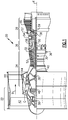
- FIG. 1 schematically illustrates a gas turbine engine 20.
- the gas turbine engine 20 is disclosed herein as a two-spool turbofan that generally incorporates a fan section 22, a compressor section 24, a combustor section 26 and a turbine section 28.
- the fan section 22 drives air along a bypass flow path B in a bypass duct defined within a nacelle 15, and also drives air along a core flow path C for compression and communication into the combustor section 26 then expansion through the turbine section 28.
- FIG. 1 schematic
- the exemplary engine 20 generally includes a low speed spool 30 and a high speed spool 32 mounted for rotation about an engine central longitudinal axis A relative to an engine static structure 36 via several bearing systems 38. It should be understood that various bearing systems 38 at various locations may alternatively or additionally be provided, and the location of bearing systems 38 may be varied as appropriate to the application.
- the low speed spool 30 generally includes an inner shaft 40 that interconnects, a first (or low) pressure compressor 44 and a first (or low) pressure turbine 46.
- the inner shaft 40 is connected to the fan 42 through a speed change mechanism, which in exemplary gas turbine engine 20 is illustrated as a geared architecture 48 to drive a fan 42 at a lower speed than the low speed spool 30.
- the high speed spool 32 includes an outer shaft 50 that interconnects a second (or high) pressure compressor 52 and a second (or high) pressure turbine 54.
- a combustor 56 is arranged in exemplary gas turbine engine 20 between the high pressure compressor 52 and the high pressure turbine 54.
- a mid-turbine frame 57 of the engine static structure 36 may be arranged generally between the high pressure turbine 54 and the low pressure turbine 46.
- the mid-turbine frame 57 further supports bearing systems 38 in the turbine section 28.
- the inner shaft 40 and the outer shaft 50 are concentric and rotate via bearing systems 38 about the engine central longitudinal axis A which is collinear with their longitudinal axes.
- the core airflow is compressed by the low pressure compressor 44 then the high pressure compressor 52, mixed and burned with fuel in the combustor 56, then expanded over the high pressure turbine 54 and low pressure turbine 46.
- the mid-turbine frame 57 includes airfoils 59 which are in the core airflow path C.
- the turbines 46, 54 rotationally drive the respective low speed spool 30 and high speed spool 32 in response to the expansion.
- gear system 48 may be located aft of the low pressure compressor, or aft of the combustor section 26 or even aft of turbine section 28, and fan 42 may be positioned forward or aft of the location of gear system 48.
- the engine 20 in one example is a high-bypass geared aircraft engine.
- the engine 20 bypass ratio is greater than about six (6), with an example embodiment being greater than about ten (10)
- the geared architecture 48 is an epicyclic gear train, such as a planetary gear system or other gear system, with a gear reduction ratio of greater than about 2.3
- the low pressure turbine 46 has a pressure ratio that is greater than about five.
- the engine 20 bypass ratio is greater than about ten (10:1)
- the fan diameter is significantly larger than that of the low pressure compressor 44
- the low pressure turbine 46 has a pressure ratio that is greater than about five 5:1.
- Low pressure turbine 46 pressure ratio is pressure measured prior to inlet of low pressure turbine 46 as related to the pressure at the outlet of the low pressure turbine 46 prior to an exhaust nozzle.
- the geared architecture 48 may be an epicycle gear train, such as a planetary gear system or other gear system, with a gear reduction ratio of greater than about 2.3:1 and less than about 5:1. It should be understood, however, that the above parameters are only exemplary of one embodiment of a geared architecture engine and that the present invention is applicable to other gas turbine engines including direct drive turbofans.
- the fan section 22 of the engine 20 is designed for a particular flight condition -- typically cruise at about 0.8 Mach and about 35,000 feet (10,668 meters).
- the flight condition of 0.8 Mach and 35,000 ft (10,668 meters), with the engine at its best fuel consumption - also known as "bucket cruise Thrust Specific Fuel Consumption ('TSFC')" - is the industry standard parameter of lbm of fuel being burned divided by lbf of thrust the engine produces at that minimum point.
- "Low fan pressure ratio” is the pressure ratio across the fan blade alone, without a Fan Exit Guide Vane (“FEGV”) system.
- the low fan pressure ratio as disclosed herein according to one non-limiting embodiment is less than about 1.45.
- the "Low corrected fan tip speed” as disclosed herein according to one non-limiting embodiment is less than about 1150 ft / second (350.5 meters/second).
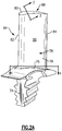
- FIG. 2A illustrates an example turbine blade 64.
- a root 74 of each turbine blade 64 is mounted to a rotor disk.
- the turbine blade 64 includes a platform 76, which provides the inner flow path, supported by the root 74.
- An airfoil 78 extends in a radial direction R (shown in Fig. 2B ) from the platform 76 to a tip 80.
- R shown in Fig. 2B
- the turbine blades may be integrally formed with the rotor such that the roots are eliminated.
- the platform is provided by the outer diameter of the rotor.
- the airfoil 78 provides leading and trailing edges 82, 84.
- the tip 80 is arranged adjacent to a blade outer air seal (not shown).
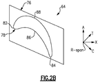
- FIGS 2A and 2B somewhat schematically illustrate an exterior airfoil surface 79 extending in a chord-wise direction C from a leading edge 82 to a trailing edge 84.
- the airfoil 78 is provided between pressure (typically concave) and suction (typically convex) walls 86, 88 in an airfoil thickness direction T, which is generally perpendicular to the chord-wise direction C.
- Multiple turbine blades 64 are arranged circumferentially in a circumferential direction A.
- the airfoil 78 extends from the platform 76 in the radial direction R, or spanwise, to the tip 80.
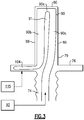
- FIG. 3 illustrates a cross-sectional view of the airfoil 78.
- the airfoil 78 has a U-shaped cooling passage 90 arranged at a position in the chord-wise direction C.
- the cooling passage 90 comprises a first passage 90a arranged on the pressure side 86, and a second passage 90b arranged on the suction side 88.
- up passages refer to cooling passages that transport cooling fluid radially outward away from the engine centerline, in a direction towards a larger radial outboard location.
- “down” passages refer to cooling passages that transport cooling fluid radially inward toward the engine centerline, in a direction towards a smaller inboard location.
- the first passage 90a is an up passage, and is fluidly connected to the second passage 90b, which is a down passage, near the tip 80 at a passage 90c.
- the first passage 90a receives cooling air from a cooling source 92, such as bleed air from the compressor section 24.
- the first and second passages 90a, 90b are separated by a rib 91.
- the Coriolis effect acts on cooling fluid as it is in motion relative to a rotating component, such as an airfoil.
- a rotating component such as an airfoil.
- inertia pushes the cooling air against a wall of the blade 64, which enhances the cooling on that wall.
- the Coriolis effect augments the heat transfer coefficient on the pressure side of an up pass and the suction side of a down pass.
- the disclosed U-shaped cooling passage arrangement takes advantage of the Coriolis effect on both the pressure and suction sides 86, 88 of the airfoil 78 as the cooling air moves circumferentially across the airfoil 78.
- the Coriolis effect improves the heat transfer coefficient on the pressure side 86 as cooling air travels up the first passage 90a and on the suction side 88 as cooling air travels down the second passage 90b.
- the airfoil 78 may include additional cooling passages 94, 96, 98, 100, 102.
- the location of the U-shaped passage 90 within the airfoil 78 is selected such that the thickness of the airfoil 78 can accommodate both the first ("up") passage 90a and the second ("down") passage 90b at the same position in the chord-wise direction C.
- the second passage 90b is fluidly connected to a platform core passage 104. Cooling air travels from the cooling source 92, up the first passage 90a to the airfoil tip 80, and down the second passage 90b.
- the platform core passage 104 is arranged in the platform 76 at the suction side 88 of the airfoil 78. In this embodiment, the platform core passage 104 does not fluidly communicate with the passages 94, 96, 98, 100, 102.
- the platform core 104 dumps the cooling air from the second passage 90b at a platform core outlet 106 near the airfoil trailing edge 84. According to the invention, the outlet 106 is aft of the arfoil trailing edge 84. There is typically a low pressure region at the wake region aft of the airfoil trailing edge 84 where the cooling air is purged.
- the platform cor passage 104 has a serpentine shape through the platform.
- Features in the platform core passage 104 such as ribs, may guide the flow through the platform 76 to prevent separation.
- This serpentine shape provides a large surface area for cooling inside the platform 76.
- the arrangement of purging the cooling air from the airfoil 78 through the platform 76 allows the same cooling air to be used to cool both the airfoil 78 and the platform 76. This reusing of the cooling air in the platform 76 may improve the overall airfoil cooling efficiency.
- FIG. 5 illustrates another embodiment according to the present invention.
- the platform 76 includes multiple platform passages 104, 108, 112. Although three platform core passages are illustrated, a platform with more or fewer platform cores may be contemplated within the scope of this disclosure.
- Each of the platform core passages 104, 108, 112 is in fluid communication with a cooling passage and purges cooling air at a platform core outlet 106, 110, 114 near the airfoil trailing edge 84.
- This arrangement with multiple platform core passages provides additional cooling in the platform 76. Additional cooling may be provided by holes 117 which are drilled into the platform passage 104, 108. These holes 117 may provide another location to purge cooling air from the platform 76.
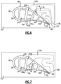
- Figure 6 illustrates another embodiment according to the present invention.
- a poorman-fed channel 116 is arranged in the platform 76.
- Poorman-fed channels typically rely on hotter air from a different source than the passages in the airfoil 78.
- the poorman-fed channel 116 receives cooling air from a cavity 115 (shown schematically in Fig. 3 ) radially inward of the platform 76, and purges the cooling air at an outlet 120 near the airfoil trailing edge 84.
- the poorman-fed channel 116 has a serpentine shape. This arrangement ensures the entire platform 76 receives cooling with a less complex circuit design.
- the poorman-fed channel 116 is located circumferentially inward of the platform core passage 104. In other embodiments, the poorman-fed channel 116 may be located circumferentially outward of the platform core passage 104. In further embodiments, the platform 76 may include multiple poorman-fed channels 116.
- the airfoil 78 may also include hybrid cavity passages 105. These hybrid cavity passages 105 along the pressure and/or suction sides 86, 88 may help shield the passage 90 and reduce heat pick up. Hybrid cavity passages 105 extend radially and are provided in a thickness direction T between a cooling passage and the airfoil surface 79 on at least one of the pressure and suction sides 86, 88. In some embodiments, additional hybrid cavity passages may be provided forward or aft of the cooling passage 90. Hybrid cavity passages 105 have a much higher width to height aspect ratio than passage 90. Hybrid cavity passages 105 protect the cooling passage 90 and root flag passage 104 from gaining heat from the core flow path C. Hybrid cavities may be particularly helpful for first stage blades, for example.
- Figure 7 illustrates another embodiment according to the present invention.
- the first and second passages 90a, 90b have a substantially triangular cross section.
- the first and second passages 90a, 90b have a substantially rectangular cross section.
- the first and second passages 90a, 90b may have the same cross-sectional shape.
- the first and second passages 90a, 90b have a width W oriented generally along the chord-wise direction C, and a height H oriented generally along the thickness direction T. In an embodiment, an aspect ratio of the width W to the height H is less than two.
- the exterior airfoil surface 79 may include film cooling holes in fluid communication with the cooling passage 90 to create a thin film boundary layer that protects the exterior airfoil 78 from hot gases in the core flow path C
- the quantity, size, orientation, and location will be dictated by the necessity to increase the local thermal cooling effectiveness and achieve the necessary thermal performance required to mitigate hot section part cooling airflow requirements, as well as, meet part and module level durability life, stage efficiency, module, and overall engine cycle performance and mission weight fuel burn requirements.
Landscapes
- Engineering & Computer Science (AREA)
- Mechanical Engineering (AREA)
- General Engineering & Computer Science (AREA)
- Turbine Rotor Nozzle Sealing (AREA)
Claims (12)
- Gasturbinentriebwerkskomponente, die Folgendes umfasst:ein Schaufelprofil (78), das eine Druck- und eine Saugseitenwand (86, 88) aufweist, die sich in einer Sehnenrichtung zwischen einer Vorderkante (82) und einer Hinterkante (84) erstrecken, wobei sich die Druck- und die Saugseitenwand (86, 88) in einer Radialrichtung zwischen einer Plattform (76) und einer Spitze (80) erstrecken, um eine äußere Schaufelprofilfläche (79) bereitzustellen;einen Kühldurchgang (90), der zwischen der Druck- und der Saugseitenwand (86, 88) angeordnet ist, die einen ersten Durchgang (90A) entlang der Druckseitenwand (86) und einen zweiten Durchgang (90B) entlang der Saugseitenwand (88) aufweisen, wobei der erste Durchgang (90A) dazu konfiguriert ist, Kühlluft aus einer Kühlluftquelle (92) aufzunehmen, und der zweite Durchgang (90B) dazu konfiguriert ist, Kühlluft aus dem ersten Durchgang (90A) nahe der Spitze (80) aufzunehmen; undeinen Plattformdurchgang (104), der in der Plattform (76) angeordnet ist, dadurch gekennzeichnet, dassder Plattformdurchgang (104) eine gewundene Form aufweist und dazu konfiguriert ist, die Kühlluft aus dem zweiten Durchgang (90B) hinter der Hinterkante (84) zu spülen.
- Komponente nach Anspruch 1, wobei der Plattformdurchgang (104) auf der Saugseite des Schaufelprofils (78) angeordnet ist.
- Komponente nach Anspruch 1 oder 2, wobei die Plattform (76) mehrere Plattformdurchgänge (104, 108, 112) beinhaltet.
- Komponente nach Anspruch 3, wobei jeder der mehreren Plattformdurchgänge (104, 108, 112) dazu konfiguriert ist, Kühlluft nahe der Hinterkante zu spülen.
- Komponente nach Anspruch 3 oder 4, wobei die Plattform (76) drei Plattformdurchgänge (104, 108, 112) beinhaltet.
- Komponente nach einem der vorhergehenden Ansprüche, wobei ein armgespeister Kanal (116) in der Plattform (76) angeordnet ist und der armgespeiste Kanal (116) dazu konfiguriert ist, Kühlluft aus einem Hohlraum (115) aufzunehmen, der sich radial innerhalb der Plattform (76) befindet.
- Komponente nach Anspruch 6, wobei der armgespeiste Kanal (116) in der Plattform (76) auf der Saugseite und innerhalb des Plattformdurchgangs (104) angeordnet ist.
- Komponente nach einem der vorhergehenden Ansprüche, wobei ein Hybrid-Hohlraum (105) auf einer der Druckseite und der Saugseite des Schaufelprofils angeordnet ist.
- Komponente nach einem der vorhergehenden Ansprüche, wobei der erste Durchgang (90A) ein Streckungsverhältnis von weniger als etwa zwei aufweist.
- Komponente nach einem der vorhergehenden Ansprüche, wobei es sich bei der Kühlluftquelle (92) um Zapfluft aus einem Verdichterabschnitt (24) eines Gasturbinentriebwerks (20) handelt.
- Gasturbinentriebwerk (20), das Folgendes umfasst:einen Brennkammerabschnitt (26), der fluidisch zwischen einem Verdichter- und einem Turbinenabschnitt (24; 28) angeordnet ist; unddie Gasturbinentriebwerkskomponente nach einem der Ansprüche 1 bis 9.
- Gasturbinentriebwerk nach Anspruch 11, wobei es sich bei der Kühlluftquelle (92) um Zapfluft aus dem Verdichterabschnitt (24) handelt.
Applications Claiming Priority (1)
| Application Number | Priority Date | Filing Date | Title |
|---|---|---|---|
| US15/968,043 US10890074B2 (en) | 2018-05-01 | 2018-05-01 | Coriolis optimized u-channel with platform core |
Publications (2)
| Publication Number | Publication Date |
|---|---|
| EP3575552A1 EP3575552A1 (de) | 2019-12-04 |
| EP3575552B1 true EP3575552B1 (de) | 2021-06-02 |
Family
ID=66334293
Family Applications (1)
| Application Number | Title | Priority Date | Filing Date |
|---|---|---|---|
| EP19171843.6A Active EP3575552B1 (de) | 2018-05-01 | 2019-04-30 | Coriolis-optimierter u-kanal mit plattformkühlung |
Country Status (2)
| Country | Link |
|---|---|
| US (1) | US10890074B2 (de) |
| EP (1) | EP3575552B1 (de) |
Family Cites Families (14)
| Publication number | Priority date | Publication date | Assignee | Title |
|---|---|---|---|---|
| US5813835A (en) | 1991-08-19 | 1998-09-29 | The United States Of America As Represented By The Secretary Of The Air Force | Air-cooled turbine blade |
| US6402471B1 (en) * | 2000-11-03 | 2002-06-11 | General Electric Company | Turbine blade for gas turbine engine and method of cooling same |
| US6974308B2 (en) * | 2001-11-14 | 2005-12-13 | Honeywell International, Inc. | High effectiveness cooled turbine vane or blade |
| US7296973B2 (en) * | 2005-12-05 | 2007-11-20 | General Electric Company | Parallel serpentine cooled blade |
| US7416391B2 (en) | 2006-02-24 | 2008-08-26 | General Electric Company | Bucket platform cooling circuit and method |
| US8523527B2 (en) * | 2010-03-10 | 2013-09-03 | General Electric Company | Apparatus for cooling a platform of a turbine component |
| US8540486B2 (en) * | 2010-03-22 | 2013-09-24 | General Electric Company | Apparatus for cooling a bucket assembly |
| US9021816B2 (en) * | 2012-07-02 | 2015-05-05 | United Technologies Corporation | Gas turbine engine turbine vane platform core |
| US9194237B2 (en) * | 2012-09-10 | 2015-11-24 | General Electric Company | Serpentine cooling of nozzle endwall |
| US9080452B2 (en) | 2012-09-28 | 2015-07-14 | United Technologies Corporation | Gas turbine engine airfoil with vane platform cooling passage |
| EP3084136B8 (de) * | 2013-12-17 | 2021-04-07 | Raytheon Technologies Corporation | Laufschaufel und zugehöriges verfahren zur kühlung einer plattform einer laufschaufel |
| US10001013B2 (en) | 2014-03-06 | 2018-06-19 | General Electric Company | Turbine rotor blades with platform cooling arrangements |
| JP5905631B1 (ja) * | 2015-09-15 | 2016-04-20 | 三菱日立パワーシステムズ株式会社 | 動翼、これを備えているガスタービン、及び動翼の製造方法 |
| US10323520B2 (en) * | 2017-06-13 | 2019-06-18 | General Electric Company | Platform cooling arrangement in a turbine rotor blade |
-
2018
- 2018-05-01 US US15/968,043 patent/US10890074B2/en active Active
-
2019
- 2019-04-30 EP EP19171843.6A patent/EP3575552B1/de active Active
Non-Patent Citations (1)
| Title |
|---|
| None * |
Also Published As
| Publication number | Publication date |
|---|---|
| EP3575552A1 (de) | 2019-12-04 |
| US10890074B2 (en) | 2021-01-12 |
| US20190338647A1 (en) | 2019-11-07 |
Similar Documents
| Publication | Publication Date | Title |
|---|---|---|
| US11148191B2 (en) | Core arrangement for turbine engine component | |
| EP2907974B1 (de) | Bauteil und zugehöriges gasturbinentriebwerk | |
| US10808546B2 (en) | Gas turbine engine airfoil trailing edge suction side cooling | |
| EP3081753B1 (de) | Schaufelspitzenkühlungsanordnung | |
| EP3543464B1 (de) | Doppelhohlraumleitblech | |
| EP3084136B1 (de) | Laufschaufel und zugehöriges verfahren zur kühlung einer plattform einer laufschaufel | |
| EP3498979B1 (de) | Gekühltes schaufelblatt | |
| EP3181823B1 (de) | Verfahren und vorrichtung zur kühlung einer gasturbinenmotorschaufel | |
| EP3078807B2 (de) | Kühlkanäle für eine gasturbinenmotorkomponente | |
| WO2014003958A1 (en) | Turbine blade platform with u-channel cooling holes | |
| EP3051066B1 (de) | Gusskern mit versetzten fortsätzen | |
| EP3051064B2 (de) | Innenkühlungshohlraum mit nockenstreifen | |
| US10001023B2 (en) | Grooved seal arrangement for turbine engine | |
| EP2927429B1 (de) | Gasturbinenkomponente mit flusstrennungsrippe | |
| EP3039247B1 (de) | Kühlanordnung mit einer übergangs- und sockelrippe für eine gasturbinenmotorschaufel | |
| EP3575552B1 (de) | Coriolis-optimierter u-kanal mit plattformkühlung | |
| EP3575553B1 (de) | Coriolis-optimierter u-kanal mit passage in form einer flagge am fusse der schaufel | |
| EP3508693B1 (de) | Segregierte kühlluftkanäle für turbinenschaufel | |
| EP3556997B1 (de) | Schaufel mit einlassöffnung an der hinteren seite der wurzel | |
| EP2977557B1 (de) | Gekühlte schaufelstruktur und zugehöriges kühlverfahren | |
| EP2942486B1 (de) | Konfiguration des kühlkanals einer gasturbinenmotorschaufel | |
| EP3550109B1 (de) | Gasturbinenkomponente mit flusstrennungsrippe | |
| EP3581762B1 (de) | Kühlkanalanordnung für gasturbinendeckband |
Legal Events
| Date | Code | Title | Description |
|---|---|---|---|
| PUAI | Public reference made under article 153(3) epc to a published international application that has entered the european phase |
Free format text: ORIGINAL CODE: 0009012 |
|
| STAA | Information on the status of an ep patent application or granted ep patent |
Free format text: STATUS: THE APPLICATION HAS BEEN PUBLISHED |
|
| AK | Designated contracting states |
Kind code of ref document: A1 Designated state(s): AL AT BE BG CH CY CZ DE DK EE ES FI FR GB GR HR HU IE IS IT LI LT LU LV MC MK MT NL NO PL PT RO RS SE SI SK SM TR |
|
| AX | Request for extension of the european patent |
Extension state: BA ME |
|
| STAA | Information on the status of an ep patent application or granted ep patent |
Free format text: STATUS: REQUEST FOR EXAMINATION WAS MADE |
|
| 17P | Request for examination filed |
Effective date: 20200529 |
|
| RBV | Designated contracting states (corrected) |
Designated state(s): AL AT BE BG CH CY CZ DE DK EE ES FI FR GB GR HR HU IE IS IT LI LT LU LV MC MK MT NL NO PL PT RO RS SE SI SK SM TR |
|
| RIC1 | Information provided on ipc code assigned before grant |
Ipc: F01D 5/18 20060101AFI20200902BHEP |
|
| GRAP | Despatch of communication of intention to grant a patent |
Free format text: ORIGINAL CODE: EPIDOSNIGR1 |
|
| STAA | Information on the status of an ep patent application or granted ep patent |
Free format text: STATUS: GRANT OF PATENT IS INTENDED |
|
| INTG | Intention to grant announced |
Effective date: 20201211 |
|
| RAP1 | Party data changed (applicant data changed or rights of an application transferred) |
Owner name: RAYTHEON TECHNOLOGIES CORPORATION |
|
| GRAS | Grant fee paid |
Free format text: ORIGINAL CODE: EPIDOSNIGR3 |
|
| GRAA | (expected) grant |
Free format text: ORIGINAL CODE: 0009210 |
|
| STAA | Information on the status of an ep patent application or granted ep patent |
Free format text: STATUS: THE PATENT HAS BEEN GRANTED |
|
| REG | Reference to a national code |
Ref country code: CH Ref legal event code: EP |
|
| AK | Designated contracting states |
Kind code of ref document: B1 Designated state(s): AL AT BE BG CH CY CZ DE DK EE ES FI FR GB GR HR HU IE IS IT LI LT LU LV MC MK MT NL NO PL PT RO RS SE SI SK SM TR |
|
| REG | Reference to a national code |
Ref country code: GB Ref legal event code: FG4D |
|
| REG | Reference to a national code |
Ref country code: AT Ref legal event code: REF Ref document number: 1398605 Country of ref document: AT Kind code of ref document: T Effective date: 20210615 |
|
| REG | Reference to a national code |
Ref country code: IE Ref legal event code: FG4D |
|
| REG | Reference to a national code |
Ref country code: DE Ref legal event code: R096 Ref document number: 602019005000 Country of ref document: DE |
|
| REG | Reference to a national code |
Ref country code: LT Ref legal event code: MG9D |
|
| PG25 | Lapsed in a contracting state [announced via postgrant information from national office to epo] |
Ref country code: FI Free format text: LAPSE BECAUSE OF FAILURE TO SUBMIT A TRANSLATION OF THE DESCRIPTION OR TO PAY THE FEE WITHIN THE PRESCRIBED TIME-LIMIT Effective date: 20210602 Ref country code: HR Free format text: LAPSE BECAUSE OF FAILURE TO SUBMIT A TRANSLATION OF THE DESCRIPTION OR TO PAY THE FEE WITHIN THE PRESCRIBED TIME-LIMIT Effective date: 20210602 Ref country code: LT Free format text: LAPSE BECAUSE OF FAILURE TO SUBMIT A TRANSLATION OF THE DESCRIPTION OR TO PAY THE FEE WITHIN THE PRESCRIBED TIME-LIMIT Effective date: 20210602 Ref country code: BG Free format text: LAPSE BECAUSE OF FAILURE TO SUBMIT A TRANSLATION OF THE DESCRIPTION OR TO PAY THE FEE WITHIN THE PRESCRIBED TIME-LIMIT Effective date: 20210902 |
|
| REG | Reference to a national code |
Ref country code: NL Ref legal event code: MP Effective date: 20210602 |
|
| REG | Reference to a national code |
Ref country code: AT Ref legal event code: MK05 Ref document number: 1398605 Country of ref document: AT Kind code of ref document: T Effective date: 20210602 |
|
| PG25 | Lapsed in a contracting state [announced via postgrant information from national office to epo] |
Ref country code: GR Free format text: LAPSE BECAUSE OF FAILURE TO SUBMIT A TRANSLATION OF THE DESCRIPTION OR TO PAY THE FEE WITHIN THE PRESCRIBED TIME-LIMIT Effective date: 20210903 Ref country code: LV Free format text: LAPSE BECAUSE OF FAILURE TO SUBMIT A TRANSLATION OF THE DESCRIPTION OR TO PAY THE FEE WITHIN THE PRESCRIBED TIME-LIMIT Effective date: 20210602 Ref country code: NO Free format text: LAPSE BECAUSE OF FAILURE TO SUBMIT A TRANSLATION OF THE DESCRIPTION OR TO PAY THE FEE WITHIN THE PRESCRIBED TIME-LIMIT Effective date: 20210902 Ref country code: PL Free format text: LAPSE BECAUSE OF FAILURE TO SUBMIT A TRANSLATION OF THE DESCRIPTION OR TO PAY THE FEE WITHIN THE PRESCRIBED TIME-LIMIT Effective date: 20210602 Ref country code: RS Free format text: LAPSE BECAUSE OF FAILURE TO SUBMIT A TRANSLATION OF THE DESCRIPTION OR TO PAY THE FEE WITHIN THE PRESCRIBED TIME-LIMIT Effective date: 20210602 Ref country code: SE Free format text: LAPSE BECAUSE OF FAILURE TO SUBMIT A TRANSLATION OF THE DESCRIPTION OR TO PAY THE FEE WITHIN THE PRESCRIBED TIME-LIMIT Effective date: 20210602 |
|
| PG25 | Lapsed in a contracting state [announced via postgrant information from national office to epo] |
Ref country code: CZ Free format text: LAPSE BECAUSE OF FAILURE TO SUBMIT A TRANSLATION OF THE DESCRIPTION OR TO PAY THE FEE WITHIN THE PRESCRIBED TIME-LIMIT Effective date: 20210602 Ref country code: AT Free format text: LAPSE BECAUSE OF FAILURE TO SUBMIT A TRANSLATION OF THE DESCRIPTION OR TO PAY THE FEE WITHIN THE PRESCRIBED TIME-LIMIT Effective date: 20210602 Ref country code: NL Free format text: LAPSE BECAUSE OF FAILURE TO SUBMIT A TRANSLATION OF THE DESCRIPTION OR TO PAY THE FEE WITHIN THE PRESCRIBED TIME-LIMIT Effective date: 20210602 Ref country code: RO Free format text: LAPSE BECAUSE OF FAILURE TO SUBMIT A TRANSLATION OF THE DESCRIPTION OR TO PAY THE FEE WITHIN THE PRESCRIBED TIME-LIMIT Effective date: 20210602 Ref country code: PT Free format text: LAPSE BECAUSE OF FAILURE TO SUBMIT A TRANSLATION OF THE DESCRIPTION OR TO PAY THE FEE WITHIN THE PRESCRIBED TIME-LIMIT Effective date: 20211004 Ref country code: SM Free format text: LAPSE BECAUSE OF FAILURE TO SUBMIT A TRANSLATION OF THE DESCRIPTION OR TO PAY THE FEE WITHIN THE PRESCRIBED TIME-LIMIT Effective date: 20210602 Ref country code: SK Free format text: LAPSE BECAUSE OF FAILURE TO SUBMIT A TRANSLATION OF THE DESCRIPTION OR TO PAY THE FEE WITHIN THE PRESCRIBED TIME-LIMIT Effective date: 20210602 Ref country code: ES Free format text: LAPSE BECAUSE OF FAILURE TO SUBMIT A TRANSLATION OF THE DESCRIPTION OR TO PAY THE FEE WITHIN THE PRESCRIBED TIME-LIMIT Effective date: 20210602 Ref country code: EE Free format text: LAPSE BECAUSE OF FAILURE TO SUBMIT A TRANSLATION OF THE DESCRIPTION OR TO PAY THE FEE WITHIN THE PRESCRIBED TIME-LIMIT Effective date: 20210602 |
|
| REG | Reference to a national code |
Ref country code: DE Ref legal event code: R097 Ref document number: 602019005000 Country of ref document: DE |
|
| PLBE | No opposition filed within time limit |
Free format text: ORIGINAL CODE: 0009261 |
|
| STAA | Information on the status of an ep patent application or granted ep patent |
Free format text: STATUS: NO OPPOSITION FILED WITHIN TIME LIMIT |
|
| PG25 | Lapsed in a contracting state [announced via postgrant information from national office to epo] |
Ref country code: DK Free format text: LAPSE BECAUSE OF FAILURE TO SUBMIT A TRANSLATION OF THE DESCRIPTION OR TO PAY THE FEE WITHIN THE PRESCRIBED TIME-LIMIT Effective date: 20210602 |
|
| 26N | No opposition filed |
Effective date: 20220303 |
|
| PG25 | Lapsed in a contracting state [announced via postgrant information from national office to epo] |
Ref country code: AL Free format text: LAPSE BECAUSE OF FAILURE TO SUBMIT A TRANSLATION OF THE DESCRIPTION OR TO PAY THE FEE WITHIN THE PRESCRIBED TIME-LIMIT Effective date: 20210602 |
|
| PG25 | Lapsed in a contracting state [announced via postgrant information from national office to epo] |
Ref country code: IT Free format text: LAPSE BECAUSE OF FAILURE TO SUBMIT A TRANSLATION OF THE DESCRIPTION OR TO PAY THE FEE WITHIN THE PRESCRIBED TIME-LIMIT Effective date: 20210602 |
|
| REG | Reference to a national code |
Ref country code: CH Ref legal event code: PL |
|
| REG | Reference to a national code |
Ref country code: BE Ref legal event code: MM Effective date: 20220430 |
|
| PG25 | Lapsed in a contracting state [announced via postgrant information from national office to epo] |
Ref country code: MC Free format text: LAPSE BECAUSE OF FAILURE TO SUBMIT A TRANSLATION OF THE DESCRIPTION OR TO PAY THE FEE WITHIN THE PRESCRIBED TIME-LIMIT Effective date: 20210602 Ref country code: LU Free format text: LAPSE BECAUSE OF NON-PAYMENT OF DUE FEES Effective date: 20220430 Ref country code: LI Free format text: LAPSE BECAUSE OF NON-PAYMENT OF DUE FEES Effective date: 20220430 Ref country code: CH Free format text: LAPSE BECAUSE OF NON-PAYMENT OF DUE FEES Effective date: 20220430 |
|
| PG25 | Lapsed in a contracting state [announced via postgrant information from national office to epo] |
Ref country code: BE Free format text: LAPSE BECAUSE OF NON-PAYMENT OF DUE FEES Effective date: 20220430 |
|
| PG25 | Lapsed in a contracting state [announced via postgrant information from national office to epo] |
Ref country code: IE Free format text: LAPSE BECAUSE OF NON-PAYMENT OF DUE FEES Effective date: 20220430 |
|
| P01 | Opt-out of the competence of the unified patent court (upc) registered |
Effective date: 20230521 |
|
| PG25 | Lapsed in a contracting state [announced via postgrant information from national office to epo] |
Ref country code: HU Free format text: LAPSE BECAUSE OF FAILURE TO SUBMIT A TRANSLATION OF THE DESCRIPTION OR TO PAY THE FEE WITHIN THE PRESCRIBED TIME-LIMIT; INVALID AB INITIO Effective date: 20190430 |
|
| PG25 | Lapsed in a contracting state [announced via postgrant information from national office to epo] |
Ref country code: MK Free format text: LAPSE BECAUSE OF FAILURE TO SUBMIT A TRANSLATION OF THE DESCRIPTION OR TO PAY THE FEE WITHIN THE PRESCRIBED TIME-LIMIT Effective date: 20210602 Ref country code: CY Free format text: LAPSE BECAUSE OF FAILURE TO SUBMIT A TRANSLATION OF THE DESCRIPTION OR TO PAY THE FEE WITHIN THE PRESCRIBED TIME-LIMIT Effective date: 20210602 |
|
| PG25 | Lapsed in a contracting state [announced via postgrant information from national office to epo] |
Ref country code: MT Free format text: LAPSE BECAUSE OF FAILURE TO SUBMIT A TRANSLATION OF THE DESCRIPTION OR TO PAY THE FEE WITHIN THE PRESCRIBED TIME-LIMIT Effective date: 20210602 |
|
| PGFP | Annual fee paid to national office [announced via postgrant information from national office to epo] |
Ref country code: DE Payment date: 20250319 Year of fee payment: 7 |
|
| REG | Reference to a national code |
Ref country code: DE Ref legal event code: R081 Ref document number: 602019005000 Country of ref document: DE Owner name: RTX CORPORATION (N.D.GES.D. STAATES DELAWARE),, US Free format text: FORMER OWNER: RAYTHEON TECHNOLOGIES CORPORATION, FARMINGTON, CT, US |
|
| PG25 | Lapsed in a contracting state [announced via postgrant information from national office to epo] |
Ref country code: TR Free format text: LAPSE BECAUSE OF FAILURE TO SUBMIT A TRANSLATION OF THE DESCRIPTION OR TO PAY THE FEE WITHIN THE PRESCRIBED TIME-LIMIT Effective date: 20210602 |
|
| PGFP | Annual fee paid to national office [announced via postgrant information from national office to epo] |
Ref country code: GB Payment date: 20260319 Year of fee payment: 8 |
|
| PGFP | Annual fee paid to national office [announced via postgrant information from national office to epo] |
Ref country code: FR Payment date: 20260319 Year of fee payment: 8 |