EP3575513A1 - Supporting system - Google Patents
Supporting system Download PDFInfo
- Publication number
- EP3575513A1 EP3575513A1 EP19158078.6A EP19158078A EP3575513A1 EP 3575513 A1 EP3575513 A1 EP 3575513A1 EP 19158078 A EP19158078 A EP 19158078A EP 3575513 A1 EP3575513 A1 EP 3575513A1
- Authority
- EP
- European Patent Office
- Prior art keywords
- bracing
- base
- support
- board
- rotary
- Prior art date
- Legal status (The legal status is an assumption and is not a legal conclusion. Google has not performed a legal analysis and makes no representation as to the accuracy of the status listed.)
- Withdrawn
Links
- 229910052782 aluminium Inorganic materials 0.000 claims abstract description 35
- XAGFODPZIPBFFR-UHFFFAOYSA-N aluminium Chemical compound [Al] XAGFODPZIPBFFR-UHFFFAOYSA-N 0.000 claims abstract description 33
- 238000009434 installation Methods 0.000 claims abstract description 19
- 230000003014 reinforcing effect Effects 0.000 claims description 23
- 238000010276 construction Methods 0.000 abstract description 8
- 238000009415 formwork Methods 0.000 description 27
- 238000000465 moulding Methods 0.000 description 23
- 238000010586 diagram Methods 0.000 description 14
- XEEYBQQBJWHFJM-UHFFFAOYSA-N Iron Chemical compound [Fe] XEEYBQQBJWHFJM-UHFFFAOYSA-N 0.000 description 12
- 229910052742 iron Inorganic materials 0.000 description 6
- 238000000034 method Methods 0.000 description 4
- 230000008569 process Effects 0.000 description 4
- 238000005516 engineering process Methods 0.000 description 3
- 230000009471 action Effects 0.000 description 2
- 230000000694 effects Effects 0.000 description 2
- 230000009286 beneficial effect Effects 0.000 description 1
- 230000008859 change Effects 0.000 description 1
- 230000009194 climbing Effects 0.000 description 1
- 238000006073 displacement reaction Methods 0.000 description 1
- 239000000463 material Substances 0.000 description 1
- 238000012986 modification Methods 0.000 description 1
- 230000004048 modification Effects 0.000 description 1
- 230000000149 penetrating effect Effects 0.000 description 1
- 238000006467 substitution reaction Methods 0.000 description 1
- 238000009827 uniform distribution Methods 0.000 description 1
- 239000002699 waste material Substances 0.000 description 1
- 238000003466 welding Methods 0.000 description 1
Images


Classifications
-
- E—FIXED CONSTRUCTIONS
- E04—BUILDING
- E04G—SCAFFOLDING; FORMS; SHUTTERING; BUILDING IMPLEMENTS OR AIDS, OR THEIR USE; HANDLING BUILDING MATERIALS ON THE SITE; REPAIRING, BREAKING-UP OR OTHER WORK ON EXISTING BUILDINGS
- E04G11/00—Forms, shutterings, or falsework for making walls, floors, ceilings, or roofs
- E04G11/36—Forms, shutterings, or falsework for making walls, floors, ceilings, or roofs for floors, ceilings, or roofs of plane or curved surfaces end formpanels for floor shutterings
- E04G11/48—Supporting structures for shutterings or frames for floors or roofs
-
- E—FIXED CONSTRUCTIONS
- E04—BUILDING
- E04G—SCAFFOLDING; FORMS; SHUTTERING; BUILDING IMPLEMENTS OR AIDS, OR THEIR USE; HANDLING BUILDING MATERIALS ON THE SITE; REPAIRING, BREAKING-UP OR OTHER WORK ON EXISTING BUILDINGS
- E04G11/00—Forms, shutterings, or falsework for making walls, floors, ceilings, or roofs
- E04G11/36—Forms, shutterings, or falsework for making walls, floors, ceilings, or roofs for floors, ceilings, or roofs of plane or curved surfaces end formpanels for floor shutterings
- E04G11/38—Forms, shutterings, or falsework for making walls, floors, ceilings, or roofs for floors, ceilings, or roofs of plane or curved surfaces end formpanels for floor shutterings for plane ceilings of concrete
-
- E—FIXED CONSTRUCTIONS
- E04—BUILDING
- E04G—SCAFFOLDING; FORMS; SHUTTERING; BUILDING IMPLEMENTS OR AIDS, OR THEIR USE; HANDLING BUILDING MATERIALS ON THE SITE; REPAIRING, BREAKING-UP OR OTHER WORK ON EXISTING BUILDINGS
- E04G11/00—Forms, shutterings, or falsework for making walls, floors, ceilings, or roofs
- E04G11/36—Forms, shutterings, or falsework for making walls, floors, ceilings, or roofs for floors, ceilings, or roofs of plane or curved surfaces end formpanels for floor shutterings
- E04G11/40—Forms, shutterings, or falsework for making walls, floors, ceilings, or roofs for floors, ceilings, or roofs of plane or curved surfaces end formpanels for floor shutterings for coffered or ribbed ceilings
-
- E—FIXED CONSTRUCTIONS
- E04—BUILDING
- E04G—SCAFFOLDING; FORMS; SHUTTERING; BUILDING IMPLEMENTS OR AIDS, OR THEIR USE; HANDLING BUILDING MATERIALS ON THE SITE; REPAIRING, BREAKING-UP OR OTHER WORK ON EXISTING BUILDINGS
- E04G11/00—Forms, shutterings, or falsework for making walls, floors, ceilings, or roofs
- E04G11/36—Forms, shutterings, or falsework for making walls, floors, ceilings, or roofs for floors, ceilings, or roofs of plane or curved surfaces end formpanels for floor shutterings
- E04G11/48—Supporting structures for shutterings or frames for floors or roofs
- E04G11/483—Supporting heads
-
- E—FIXED CONSTRUCTIONS
- E04—BUILDING
- E04G—SCAFFOLDING; FORMS; SHUTTERING; BUILDING IMPLEMENTS OR AIDS, OR THEIR USE; HANDLING BUILDING MATERIALS ON THE SITE; REPAIRING, BREAKING-UP OR OTHER WORK ON EXISTING BUILDINGS
- E04G13/00—Falsework, forms, or shutterings for particular parts of buildings, e.g. stairs, steps, cornices, balconies foundations, sills
- E04G13/04—Falsework, forms, or shutterings for particular parts of buildings, e.g. stairs, steps, cornices, balconies foundations, sills for lintels, beams, or transoms to be encased separately; Special tying or clamping means therefor
-
- E—FIXED CONSTRUCTIONS
- E04—BUILDING
- E04G—SCAFFOLDING; FORMS; SHUTTERING; BUILDING IMPLEMENTS OR AIDS, OR THEIR USE; HANDLING BUILDING MATERIALS ON THE SITE; REPAIRING, BREAKING-UP OR OTHER WORK ON EXISTING BUILDINGS
- E04G5/00—Component parts or accessories for scaffolds
- E04G5/02—Scaffold feet, e.g. with arrangements for adjustment
-
- E—FIXED CONSTRUCTIONS
- E04—BUILDING
- E04G—SCAFFOLDING; FORMS; SHUTTERING; BUILDING IMPLEMENTS OR AIDS, OR THEIR USE; HANDLING BUILDING MATERIALS ON THE SITE; REPAIRING, BREAKING-UP OR OTHER WORK ON EXISTING BUILDINGS
- E04G9/00—Forming or shuttering elements for general use
- E04G9/02—Forming boards or similar elements
- E04G9/06—Forming boards or similar elements the form surface being of metal
Definitions
- the present invention relates to the technical field, specifically, which relating to a fast moving installation supporting system.
- Construction formwork a type of supporting tools which is commonly used for building molding, are mainly used for providing temporary support. They need to be made by building formwork of corresponding shapes according to the building structure, shape and dimensions.
- building gantries are made according to building requirements, and thus cannot be moved after installation. After the task of supporting a floor slab formwork has been finished, building gantries can only be moved to a next floor to be supported by repeated dismantling and installation. Moreover, due to the rigidity requirement of support and the need for a certain load, building gantries have a large overall weight. As such, for operating worker, the operation process is less flexible, such that the construction efficiency is low, and safety issues are prone to arise.
- the present invention provides a fast moving installation supporting system that is movable and has strong applicability.
- the present invention open the fast moving installation supporting system which comprises a number of movable support devices, and each movable support device comprises a support device, a movable device, a support anchor device and an angle bracket device, wherein the movable device can dismantle and install at the bottom of the support device; the support anchor device and the angle bracket device can be respectively dismantled and installed on the top of the support device; the support device comprises a supporting structure, a connecting bracket, at least one working platform, at least one skirting board, an aluminum I-shaped board and a mounting flat plate; wherein the connecting bracket is equipped with the supporting structure; at least one working platform is installed on the connecting bracket; at least one skirting board is installed on at least one working platform and located on one side of the supporting structure, and the aluminum I-shaped board is equipped on the top of the supporting structure; the mounting flat plate is installed above the aluminum I-shaped board; the movable device is installed at the bottom of the supporting structure; the angle bracket device is installed on the mounting flat plate; the support anchor device comprises a
- the rotary unit also comprises a clamping annular groove, wherein the clamping annular groove is equipped with one side of the rotary unit and arranged annularly around the rotary hole; the rotary unit is equipped on the top of the base through the clamping annular groove.
- the rotary adjustable device also comprises at least one rotary handle, wherein at least one rotary handle is fixed on an outer wall of the rotary unit.
- the base comprises a circular through-pipe, a base bottom board and two base side boards; wherein the circular through-pipe penetrates through the base bottom board and the bracing hole; the two base side boards are connected perpendicularly to the base bottom board; the bottom surface of the base bottom board cooperates with inner side surfaces of the two base side boards to form a base bracing groove; the bracing strut penetrates through the circular through-pipe.
- the base also comprises at least one first reinforcing board, wherein the first reinforcing board is connected respectively with the circular through-pipe and the base side boards.
- the brace comprises a bracing bottom board and two bracing side boards which are connected vertically with the bracing bottom board, wherein a top surface of the bracing bottom board cooperates with inner side surfaces of the two bracing side boards to form a supporting bracing groove; one side of the bracing strut is connected to the bottom surface of the bracing bottom board.
- the brace also comprises at least one second reinforcing board, wherein the second reinforcing board is connected respectively with the bracing bottom board and the bracing strut.
- the bracing side boards are each equipped with at least one reinforcing threaded hole.
- the fast moving installation supporting system of the invention is equipped with a height-adjustable support anchor device, which can be retractable in height by whirling the rotary adjustable device of the support anchor device, so that the invention can be suitable to the different floor heights and provide support of different heights.
- the invention is equipped with a movable device, which enables the invention to perform rapid moving to a to-be-constructed area and increase the progress of construction.
- Reference numerals are illustrated as follows: 10-movable support device; 20-molding formwork; 30-support beam; 11-support device; 12-movable device; 13-support anchor device; 14-angle bracket device; 111-supporting structure; 112-connecting bracket; 113-working platform; 114-skirting board; 115-aluminum I-shaped board; 116-mounting flat plate; 1161-mounting threaded hole; 131-rotary adjustable device; 132-base; 133-channel; 134-bracing strut; 135-brace; 1311-rotary unit; 13111-rotary hole; 1331-bracing hole; 141-angle bracket; 1411-angle bracket fixing threaded hole; 142-angle bracket reinforcing device; 1421-corner iron; 1422-pin; 1423-adjusting threaded rod; 1424-abutment; 1111-aluminum top supporter; 1112-adjusting screw; 1113-scale; 1111A-outer aluminum top supporter; 1111B-inner
- the implementation of the present invention provides a movable and strong applicable of a fast moving installation supporting system, which is mainly used for supporting of a floor molding formwork 20, such that the floor is solidified and formed after pouring of concrete is completed.
- FIG. 1 illustrated is a structural schematic diagram of a movable support device in accordance with the implementation.
- the fast moving installation supporting system comprises a number of movable support devices 10.
- Each movable support device 10 comprises a support device 11, a movable device 12, a support anchor device 13 and an angle bracket device 14, wherein the support device 11 is used for providing support and installation, on which the movable device 12, the support anchor device 13 and the angle bracket device 14.
- the movable device 12 is used for the present invention with a moving function, such that after the task of supporting and setting is finished, the present invention can be rapidly moved to a next working region.
- the support anchor device 13 is used for supporting a floor molding formwork 20 for a building floor; the angle bracket device 14 is used for supporting and fixing a molding formwork 20 applied to a beam structure of a floor.
- the support anchor device 13 and the angle bracket device 14 come into contact with the molding formwork 20 through a support beam 30.
- the movable device 12 can dismantle and install at the bottom of the support device 11, and the support anchor device 13 and the angle bracket device 14 can be respectively dismantled and installed on the top of the support device 11.
- FIG. 2 is a top view of a mounting flat plate in accordance with the implementation.
- the support device 11 comprises a supporting structure 111, a connecting bracket 112, at least one working platform 113, at least one skirting board 114, an aluminum I-shaped board 115 and a mounting flat plate 116, wherein the connecting bracket 112 is equipped with the supporting structure 111; at least one working platform 113 is installed on the connecting bracket 112; at least one skirting board 114 is installed on at least one working platform 113, and located on one side of the supporting structure 111, wherein the numbers of working platforms 113 and skirting boards 114 are set which based on the demand of on-site construction; the aluminum I-shaped board 115 is equipped on the top of the supporting structure 111; the mounting flat plate 116 is installed above the aluminum I-shaped board 115, wherein the mounting flat plate 116 is equipped with a number of mounting threaded holes 1161 which arranged at intervals; the movable device is installed at the bottom of the supporting structure 111, a connecting
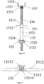
- Figures 3-6 are, a main view of a support anchor device, a side view of the support anchor device, a top view of a rotary adjustable device, and a structural schematic diagram of a channel in accordance with the implementation.
- the support anchor device 13 comprises a rotary adjustable device 131, a base 132, a channel 133, a bracing strut 134 and a brace 135, wherein the rotary adjustable device 131 comprises a rotary unit 1311; a middle portion of the rotary unit 1311 is equipped with a rotary hole 13111; the rotary hole 13111 passes through the rotary unit 1311; an inner wall of the rotary hole 13111 is equipped with an internal thread; the rotary unit 1311 is equipped on the top of the base 132; the bottom end of the base 132 is equipped with the channel 133; the bottom of the channel 133 is connected with the mounting flat plate 116; the channel 133 is equipped with at least one bracing hole 1331; the bracing strut 134 is equipped with an external thread mated with the internal thread; one side of the bracing strut 134 penetrates through the rotary unit 1311, the base 132, the bracing hole 1331 and the mounting flat plate 116, wherein the bracing
- FIG. 7 is a side view of an angle bracket device in accordance with the implementation.
- the angle bracket device 14 comprises a number of angle brackets 141, and the bottom of each angle bracket 141 is equipped with a number of angle bracket fixing threaded holes 1411.
- the angle bracket fixing threaded holes 1411 and mounting threaded holes 1161 are connected by screws, such that the angle brackets 141 can be respectively dismantled and installed on the mounting flat plate 116.
- Side boards of a molding formwork 20 that correspond to a beam structure are fixed using a number of angle brackets 141.
- the angle bracket device 14 also comprises a number of angle bracket reinforcing devices 142 corresponding to the angle brackets 141, and each angle bracket reinforcing device 142 comprises an corner iron 1421, a pin 1422, an adjusting threaded rod 1423 and an abutment 1424, wherein a top of the pin 1422 is fixed on the corner iron 1421 by welding, and the bottom end of the pin 1422 penetrates through a corresponding mounting threaded hole 1161 on the mounting flat plate 116 and is fixed by an insert, such that the corner iron 1421 is fixed on one side of a corresponding angle bracket 141 that is away from the molding formwork 20; the adjusting threaded rod 1423 penetrates through the corner iron 1421 in a threaded manner, and the abutment 1424 is fixed on an end thereof; the abutment 1424 has a flat surface, and the adjusting threaded rod 1423 is rotated to move towards the angle
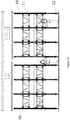
- FIGS 8-10 they are, respectively, a first reference diagram for the use of a fast moving installation supporting system, a top view of a movable support device in Figure 8 , and a second reference diagram for the use of the fast moving installation supporting system in accordance with the implementation.
- the number of movable support devices 10, the numbers of support anchor devices 13 and angle bracket devices 14, and positions thereof on the movable support devices 10 are set which based on floor molding formwork 20 for a floor to be poured.
- floor molding formwork 20 For a floor to be poured.
- mounting of a movable device 12 is not required.
- the bottom board of a molding formwork 20 corresponding to a beam structure portion is supported by a mounting flat plate 116, and side boards of the molding formwork 20 corresponding to the beam structure portion are fixed by an angle bracket device 14.
- a molding formwork 20 corresponding to a floor is fixed by a support anchor device 13.
- the support anchor device 13 When the rotary unit 1311 is whirled, under the action of the threaded connection between the bracing strut 134, and the rotary hole 13111, is rotatably retractable in the direction of its central axis; eventually, the brace 135 is pressed against the molding formwork 20 corresponding to the floor. As such, the floor molding formwork 20 is installed on the fast moving installation supporting system. Moreover, the height of the supporting structure 111 is adjusted based on building requirements, such that the overall height of the floor molding formwork 20 meets the building design requirements. Then, after concrete is poured, the support anchor device 13, the angle bracket device 14 and the molding formwork 20 are dismantled after the concrete is solidified and formed.
- the present invention is separated from a formed concrete floor by adjusting the height of the supporting structure 111. Then, the movable device 12 is installed at the bottom of the supporting structure 111, and the present invention is moved to a next position to be poured by the movable device 12. Thereafter, after the movable device 12 is dismantled, the above-mentioned steps are repeated to achieve support for another floor.
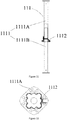
- Figures 11, 12 and 13 are, a structural schematic diagram of a supporting structure, a structural schematic diagram of an outer aluminum top supporter, and a structural schematic diagram of an inner aluminum top supporter in accordance with the implementation.
- the supporting structure 111 comprises a number of aluminum top supporters 1111, a number of adjusting screws 1112 and a number of scales 1113, and the number of adjusting screws 1112 are equipped with the number of aluminum top supporters 1111.
- the number of scales 1113 are equipped with the number of aluminum top supporters 1111 and located on one sides of the number of adjusting screws 1112. Every two adjacent aluminum top supporters 1111 are connected by a connecting bracket 112, such that a number of aluminum top supporters 1111 are fixed together.
- a single aluminum top supporter 1111 comprises an outer aluminum top supporter 1111A and an inner aluminum top supporter 1111B, and the inner aluminum top supporter 1111B is inlaid in the interior of the outer aluminum top supporter 1111A.
- the manner for adjusting the height of the support device 11 may be as follows: first, a number of adjusting screws 1112 are loosened; then, the length of the inner aluminum top supporter 1111B that is inlaid in the outer aluminum top supporter 1111A is adjusted according to marks of a number of scales 1113; after the length of the inner aluminum top supporter 1111B that is inlaid in the outer aluminum top supporter 1111A reaches a predetermined value, the number of adjusting screws 1112 are tightened, thereby reaching the purpose of adjusting the height of the movable support device 10.
- the support device 11 also comprises a ladder 117 which arranged on one side of the supporting structure 111 and connected with at least one working platform 113 and the ground.
- the ladder 117 makes it convenient for operating worker to climb up and down, and for materials to be delivered to and from, the working platform 113, thereby improving the working efficiency and reducing the risk encountered by the operating worker when climbing up and down the working platform 113.
- the ladder 117 can be retracted, it can make it convenient for operating worker to move the movable support device 10.
- the movable device 12 comprises a number of moving rollers 121 can dismantle and install at the bottom of a number of aluminum top supporters 1111 by screws, and the number of the number of moving rollers 121 corresponds to that of the number of aluminum top supporters 1111.
- a number of moving rollers 121 are installed correspondingly at the bottom of a number of aluminum top supporters 1111 by operating worker, such that they can rapidly push the movable support device 10 to a predetermined position with little effort.
- the movable device 12 is removed by the operating worker, and the movable support device 10 can then be put into use, it can improve the overall construction efficiency.
- the rotary unit 1311 also comprises a clamping annular groove 13112 which equipped with one side of the rotary unit 1311 and arranged annularly around the rotary hole 13111, wherein the minimum inner diameter of the clamping annular groove 13112 is greater than the hole diameter of the rotary hole 13111, and the rotary unit 1311 is equipped on the top of the base 132 through the clamping annular groove 13112.
- the clamping annular groove 13112 is designed to have a step-shaped cross-section, and the top of the base 132 is also designed to be of a matched stepped shape.
- the rotary adjustable device 131 also comprises at least one rotary handle 1312. At least one rotary handle 1312 is fixed on an outer wall of the rotary unit 1311, such that with this rotary handle 1312, operating worker can conduct rotation more easily and quickly.
- the base 132 comprises a circular through-pipe 1321, a base bottom board 1322 and two base side boards 1323.
- the circular through-pipe 1321 penetrates through the base bottom board 1322 and the bracing hole 1331, and the two base side boards 1323 are connected perpendicularly to the base bottom board 1322.
- the bottom of the base 132 is designed to be of a U-shaped structure, such that it is well mated with the overall shape of the channel 133.
- the bottom surface of the base bottom board 1322 cooperates with inner side surfaces of the two base side boards 1323 to form a base bracing groove, and the bracing strut 134 penetrates through the circular through-pipe 1321.
- the fixing between the base 132 and the channel 133 is reinforced by making the circular through-pipe 1321 pass through the bracing hole 1331.
- the bracing strut 134 is firmer when penetrating through the circular through-pipe 1321 of an elongated shape.
- the base 132 also comprises at least one first reinforcing board 1324 connected respectively with the circular through-pipe 1321 and the base 132 bottom board, and the support strength of the base 132 is improved by the first reinforcing board 1324.
- the brace 135 comprises a bracing bottom board 1351 and two bracing side boards 1352 which are connected vertically with the bracing bottom board 1351 in a perpendicular manner, wherein a top surface of the bracing bottom board 1351 cooperates with inner side surfaces of the two bracing side boards 1352 to form a supporting bracing groove, i.e. that the brace 135 is designed to be of a U-shaped structure, and one side of the bracing strut 134 is connected to the bottom surface of the bracing bottom board 1351.
- the brace 135 is designed to be of a U-shaped structure, such that it is well mated with the shape of a support beam.
- the brace 135 also comprises at least one second reinforcing board 1353 which is connected respectively with the bracing bottom board 1351 and the brace 135, and the support strength of the brace 135 is improved by the second reinforcing board 1353.
- the bracing side boards 1352 are equipped with at least one reinforcing threaded hole 13521.
- the brace 135 After the brace 135 is pressed against the support beam 30 of an upper floor, it may be fixed, via screws, on the support beam 30 through the reinforcing threaded holes 13521, thereby further reinforcing the fixing between the present invention and the support beam 30.
- the channel 133 is vertical to the mounting flat plate 116, the base 132 bracing groove is equipped with the channel 133, and the circular through-pipe 1321 is made to penetrate through the bracing hole 1331.
- the rotary unit 1311 is whirled by the rotary handle 1312, such that the bracing strut 134 stretches upwards in an axis direction thereof until the supporting bracing groove is equipped with the support beam 30 of a corresponding upper floor molding formwork 20. After that, the positioning and supporting process is completed.
- each bracing hole 1331 corresponds to a group consisting of a rotary adjustable device 131, a base 132, a bracing strut 134 and a brace 135. This can save design costs.
- FIG. 14 illustrated is a main view of a support anchor device in accordance with the implementation.
- the brace 135 may apply a truncated-cone structure, wherein the area for the top surface is greater than that for the bottom surface.
- the brace 135 having a truncated-cone structure can effectively enhance the support and fixing effects of the support anchor device 13.
- the fast moving installation supporting system of the invention is equipped with a height-adjustable support anchor device 13, which can be retractable in height by whirling the rotary adjustable device 131 of the support anchor device 13, so that the invention can be suitable to the different floor heights and provide support of different heights.
- the invention is equipped with a movable device, which enables the invention to perform rapid moving and increase the progress of construction.
Abstract
Description
- The present invention relates to the technical field, specifically, which relating to a fast moving installation supporting system.
- Construction formwork, a type of supporting tools which is commonly used for building molding, are mainly used for providing temporary support. They need to be made by building formwork of corresponding shapes according to the building structure, shape and dimensions.
- Moreover, traditional building formwork used timber molding formwork made up by wooden panels and patterns at the same time. Floor between floors are generally supported by a number of wooden columns which nailed to the panel become the supporting slab in order to support the floor slab formwork. Although wooden panel supports are simple in structure, however, nailing and shape cutting need to be conducted manually, the whole process is time-consuming and laboursome. Moreover, as the distance between floors is inconsistent for different buildings, wooden panel supports for the same floor cannot be reused, which results in high construction costs and waste of resources. Therefore, in current technology, traditional wooden panel supports are commonly replaced with recyclable building gantries for support.
- However, existing building gantries are made according to building requirements, and thus cannot be moved after installation. After the task of supporting a floor slab formwork has been finished, building gantries can only be moved to a next floor to be supported by repeated dismantling and installation. Moreover, due to the rigidity requirement of support and the need for a certain load, building gantries have a large overall weight. As such, for operating worker, the operation process is less flexible, such that the construction efficiency is low, and safety issues are prone to arise.
- In view of the drawbacks of current technology, the present invention provides a fast moving installation supporting system that is movable and has strong applicability.
- The present invention open the fast moving installation supporting system which comprises a number of movable support devices, and each movable support device comprises a support device, a movable device, a support anchor device and an angle bracket device, wherein the movable device can dismantle and install at the bottom of the support device; the support anchor device and the angle bracket device can be respectively dismantled and installed on the top of the support device; the support device comprises a supporting structure, a connecting bracket, at least one working platform, at least one skirting board, an aluminum I-shaped board and a mounting flat plate; wherein the connecting bracket is equipped with the supporting structure; at least one working platform is installed on the connecting bracket; at least one skirting board is installed on at least one working platform and located on one side of the supporting structure, and the aluminum I-shaped board is equipped on the top of the supporting structure; the mounting flat plate is installed above the aluminum I-shaped board; the movable device is installed at the bottom of the supporting structure; the angle bracket device is installed on the mounting flat plate; the support anchor device comprises a rotary adjustable device, a base, a channel, a bracing strut and a brace, wherein the rotary adjustable device comprises a rotary unit; a middle portion of the rotary unit is equipped with a rotary hole; the rotary hole passes through the rotary unit; an inner wall of the rotary hole is equipped with an internal thread; the rotary unit is equipped on the top of the base; the bottom of the base is equipped with the channel; the channel is equipped with at least one bracing hole; the bracing strut is equipped with an external thread mated with the internal thread; one side of the bracing strut penetrates through the rotary unit, the base, the bracing hole and the mounting flat plate, and the other side is connected with the brace.
- According to the implementation of the present invention, the rotary unit also comprises a clamping annular groove, wherein the clamping annular groove is equipped with one side of the rotary unit and arranged annularly around the rotary hole; the rotary unit is equipped on the top of the base through the clamping annular groove.
- According to the implementation of the present invention, the rotary adjustable device also comprises at least one rotary handle, wherein at least one rotary handle is fixed on an outer wall of the rotary unit.
- According to the implementation of the present invention, the base comprises a circular through-pipe, a base bottom board and two base side boards; wherein the circular through-pipe penetrates through the base bottom board and the bracing hole; the two base side boards are connected perpendicularly to the base bottom board; the bottom surface of the base bottom board cooperates with inner side surfaces of the two base side boards to form a base bracing groove; the bracing strut penetrates through the circular through-pipe.
- According to the implementation of the present invention, the base also comprises at least one first reinforcing board, wherein the first reinforcing board is connected respectively with the circular through-pipe and the base side boards.
- According to the implementation of the present invention, the brace comprises a bracing bottom board and two bracing side boards which are connected vertically with the bracing bottom board, wherein a top surface of the bracing bottom board cooperates with inner side surfaces of the two bracing side boards to form a supporting bracing groove; one side of the bracing strut is connected to the bottom surface of the bracing bottom board.
- According to the implementation of the present invention, the brace also comprises at least one second reinforcing board, wherein the second reinforcing board is connected respectively with the bracing bottom board and the bracing strut.
- According to the implementation of the present invention, the bracing side boards are each equipped with at least one reinforcing threaded hole.
- The beneficial effects that distinguish the present invention from current technology are as follows: the fast moving installation supporting system of the invention is equipped with a height-adjustable support anchor device, which can be retractable in height by whirling the rotary adjustable device of the support anchor device, so that the invention can be suitable to the different floor heights and provide support of different heights. Meanwhile, the invention is equipped with a movable device, which enables the invention to perform rapid moving to a to-be-constructed area and increase the progress of construction.
- The brief description of the figures are used for providing a further understanding of the present application, which constitute part of the present application. The implementation of the present application and illustration are used for explaining the present application, and do not constitute improper limitations. In the figures:
-
Figure 1 is a structural schematic diagram of a movable support device in accordance with the implementation; -
Figure 2 is a top view of a mounting flat plate in accordance with the implementation; -
Figure 3 is a main view of a support anchor device in accordance with the implementation; -
Figure 4 is a side view of the support anchor device in accordance with the implementation; -
Figure 5 is a top view of a rotary adjustable device in accordance with the implementation; -
Figure 6 is a structural schematic diagram of a channel in accordance with the implementation; -
Figure 7 is a side view of an angle bracket device in accordance with the implementation; -
Figure 8 illustrates a first reference diagram for the use of a fast moving installation supporting system in accordance with the implementation; -
Figure 9 is a top view of a movable support device inFigure 8 ; -
Figure 10 illustrates a second reference diagram for the use of the fast moving installation supporting system in accordance with the implementation; -
Figure 11 is a structural schematic diagram of a supporting structure in accordance with the implementation; -
Figure 12 is a structural schematic diagram of an outer aluminum top supporter in accordance with the implementation; -
Figure 13 is a structural schematic diagram of an inner aluminum top supporter in accordance with the implementation; and -
Figure 14 is a main view of a support anchor device in accordance with the implementation. - Reference numerals are illustrated as follows: 10-movable support device; 20-molding formwork; 30-support beam; 11-support device; 12-movable device; 13-support anchor device; 14-angle bracket device; 111-supporting structure; 112-connecting bracket; 113-working platform; 114-skirting board; 115-aluminum I-shaped board; 116-mounting flat plate; 1161-mounting threaded hole; 131-rotary adjustable device; 132-base; 133-channel; 134-bracing strut; 135-brace; 1311-rotary unit; 13111-rotary hole; 1331-bracing hole; 141-angle bracket; 1411-angle bracket fixing threaded hole; 142-angle bracket reinforcing device; 1421-corner iron; 1422-pin; 1423-adjusting threaded rod; 1424-abutment; 1111-aluminum top supporter; 1112-adjusting screw; 1113-scale; 1111A-outer aluminum top supporter; 1111B-inner aluminum top supporter; 117-ladder; 121-moving roller; 13112-clamping annular groove; 1312-rotary handle; 1321-circular through-pipe; 1322-base bottom board; 1323-base side board; 1324-first reinforcing board; 1351-bracing bottom board; 1352-bracing side board; 1353-second reinforcing board; 13521-reinforcing threaded hole; 1331-bracing hole.
- A number of implementations of the present invention will be disclosed below in conjunction with the accompanying figures. For the sake of clarity, many practical details will also be explained in the following description. However, it should be appreciated that these practical details should not be used to limit the present invention. In other words, in some implementations of the present invention, these practical details are not necessary. Besides, in order to simplify the accompanying figures, some conventional structures and components will be illustrated in the accompanying figures in a simple schematic manner.
- It should be noted that all the directional indications (e.g., up, down, left, right, front, behind, etc.) set forth in the implementation of the present invention are merely used for explaining relative positional relationships, motion conditions and like among various components under a particular posture (e.g., as shown in the figures), and if this particular posture changes, these directional indications also change accordingly.
- In addition, in the present invention, the descriptions such as those involving "first", "second" and the like are used merely for the purpose of description. They are not used for referring specifically to sequences or the order of precedence, nor are they used for limiting the present invention. Rather, these descriptions are merely used for distinguishing between components or operations described using the same technical term, and cannot be construed as indicating or implying their relative significance, or implicitly stating the number of indicated technical features. Therefore, features defining "first" and "second" may expressly or implicitly comprise at least one of these features. Moreover, technical solutions among various implementation may be combined with one another, but this must be done on the basis that such combinations can be achieved by those technicians. When combinations of technical solutions are mutually conflicting or cannot be achieved, it should be considered that such combinations of technical solutions do not exist, nor do they fall within the scope of protection as set forth in the present invention.
- The implementation of the present invention provides a movable and strong applicable of a fast moving installation supporting system, which is mainly used for supporting of a
floor molding formwork 20, such that the floor is solidified and formed after pouring of concrete is completed. - Referring to
Figure 1 , illustrated is a structural schematic diagram of a movable support device in accordance with the implementation. - The fast moving installation supporting system comprises a number of
movable support devices 10. Eachmovable support device 10 comprises asupport device 11, amovable device 12, asupport anchor device 13 and anangle bracket device 14, wherein thesupport device 11 is used for providing support and installation, on which themovable device 12, thesupport anchor device 13 and theangle bracket device 14. Themovable device 12 is used for the present invention with a moving function, such that after the task of supporting and setting is finished, the present invention can be rapidly moved to a next working region. Thesupport anchor device 13 is used for supporting afloor molding formwork 20 for a building floor; theangle bracket device 14 is used for supporting and fixing amolding formwork 20 applied to a beam structure of a floor. In order to make action force more uniform distribution to themolding formwork 20 by thesupport anchor device 13 and theangle bracket device 14, thesupport anchor device 13 and theangle bracket device 14 come into contact with themolding formwork 20 through asupport beam 30. Themovable device 12 can dismantle and install at the bottom of thesupport device 11, and thesupport anchor device 13 and theangle bracket device 14 can be respectively dismantled and installed on the top of thesupport device 11. - With continued reference to
Figure 1 and Figure 2, Figure 2 is a top view of a mounting flat plate in accordance with the implementation. Thesupport device 11 comprises a supportingstructure 111, a connectingbracket 112, at least one working platform 113, at least oneskirting board 114, an aluminum I-shapedboard 115 and a mountingflat plate 116, wherein the connectingbracket 112 is equipped with the supportingstructure 111; at least one working platform 113 is installed on the connectingbracket 112; at least oneskirting board 114 is installed on at least one working platform 113, and located on one side of the supportingstructure 111, wherein the numbers of working platforms 113 and skirtingboards 114 are set which based on the demand of on-site construction; the aluminum I-shapedboard 115 is equipped on the top of the supportingstructure 111; the mountingflat plate 116 is installed above the aluminum I-shapedboard 115, wherein the mountingflat plate 116 is equipped with a number of mounting threadedholes 1161 which arranged at intervals; the movable device is installed at the bottom of the supportingstructure 111; the angle bracket device is installed on the mountingflat plate 116 using the mounting threadedholes 1161. The overall height of thesupport device 11 can be adjusted by adjusting the supportingstructure 111, such that the present invention is suitable for different heights of supporting floors. - Referring to
Figures 1 ,3 ,4, 5 and6 ,Figures 3-6 are, a main view of a support anchor device, a side view of the support anchor device, a top view of a rotary adjustable device, and a structural schematic diagram of a channel in accordance with the implementation. Thesupport anchor device 13 comprises a rotaryadjustable device 131, abase 132, achannel 133, a bracingstrut 134 and abrace 135, wherein the rotaryadjustable device 131 comprises arotary unit 1311; a middle portion of therotary unit 1311 is equipped with arotary hole 13111; therotary hole 13111 passes through therotary unit 1311; an inner wall of therotary hole 13111 is equipped with an internal thread; therotary unit 1311 is equipped on the top of thebase 132; the bottom end of thebase 132 is equipped with thechannel 133; the bottom of thechannel 133 is connected with the mountingflat plate 116; thechannel 133 is equipped with at least one bracinghole 1331; the bracingstrut 134 is equipped with an external thread mated with the internal thread; one side of the bracingstrut 134 penetrates through therotary unit 1311, thebase 132, the bracinghole 1331 and the mountingflat plate 116, wherein the bracingstrut 134 penetrates through a mounting threadedhole 1161 of the mountingflat plate 116, and the other side of the bracingstrut 134 is connected with thebrace 135. - Referring to
Figures 1 and7, Figure 7 is a side view of an angle bracket device in accordance with the implementation. Theangle bracket device 14 comprises a number ofangle brackets 141, and the bottom of eachangle bracket 141 is equipped with a number of angle bracket fixing threadedholes 1411. The angle bracket fixing threadedholes 1411 and mounting threadedholes 1161 are connected by screws, such that theangle brackets 141 can be respectively dismantled and installed on the mountingflat plate 116. Side boards of amolding formwork 20 that correspond to a beam structure are fixed using a number ofangle brackets 141. In another implementation, in order to reinforce the fixing ofangle brackets 141 for amolding formwork 20, theangle bracket device 14 also comprises a number of anglebracket reinforcing devices 142 corresponding to theangle brackets 141, and each anglebracket reinforcing device 142 comprises ancorner iron 1421, apin 1422, an adjusting threadedrod 1423 and anabutment 1424, wherein a top of thepin 1422 is fixed on thecorner iron 1421 by welding, and the bottom end of thepin 1422 penetrates through a corresponding mounting threadedhole 1161 on the mountingflat plate 116 and is fixed by an insert, such that thecorner iron 1421 is fixed on one side of acorresponding angle bracket 141 that is away from themolding formwork 20; the adjusting threadedrod 1423 penetrates through thecorner iron 1421 in a threaded manner, and theabutment 1424 is fixed on an end thereof; theabutment 1424 has a flat surface, and the adjusting threadedrod 1423 is rotated to move towards theangle bracket 141 relative to thecorner iron 1421, such that eventually, the flat surface of theabutment 1424 abuts against a side surface of theangle bracket 141, thereby reinforcing the fixing of theangle bracket 141 for side boards of themolding formwork 20 that correspond to the beam structure. - Referring to
Figures 8-10 , they are, respectively, a first reference diagram for the use of a fast moving installation supporting system, a top view of a movable support device inFigure 8 , and a second reference diagram for the use of the fast moving installation supporting system in accordance with the implementation. - When the fast moving installation supporting system is used, the number of
movable support devices 10, the numbers ofsupport anchor devices 13 andangle bracket devices 14, and positions thereof on themovable support devices 10 are set which based onfloor molding formwork 20 for a floor to be poured. During mounting offloor molding formwork 20, mounting of amovable device 12 is not required. The bottom board of amolding formwork 20 corresponding to a beam structure portion is supported by a mountingflat plate 116, and side boards of themolding formwork 20 corresponding to the beam structure portion are fixed by anangle bracket device 14. Moreover, amolding formwork 20 corresponding to a floor is fixed by asupport anchor device 13. During adjustment of thesupport anchor device 13, when therotary unit 1311 is whirled, under the action of the threaded connection between the bracingstrut 134, and therotary hole 13111, is rotatably retractable in the direction of its central axis; eventually, thebrace 135 is pressed against themolding formwork 20 corresponding to the floor. As such, thefloor molding formwork 20 is installed on the fast moving installation supporting system. Moreover, the height of the supportingstructure 111 is adjusted based on building requirements, such that the overall height of thefloor molding formwork 20 meets the building design requirements. Then, after concrete is poured, thesupport anchor device 13, theangle bracket device 14 and themolding formwork 20 are dismantled after the concrete is solidified and formed. After that, the present invention is separated from a formed concrete floor by adjusting the height of the supportingstructure 111. Then, themovable device 12 is installed at the bottom of the supportingstructure 111, and the present invention is moved to a next position to be poured by themovable device 12. Thereafter, after themovable device 12 is dismantled, the above-mentioned steps are repeated to achieve support for another floor. - Further, referring to
Figures 1 ,11 ,12 and13 ,Figures 11, 12 and13 are, a structural schematic diagram of a supporting structure, a structural schematic diagram of an outer aluminum top supporter, and a structural schematic diagram of an inner aluminum top supporter in accordance with the implementation. The supportingstructure 111 comprises a number ofaluminum top supporters 1111, a number of adjustingscrews 1112 and a number ofscales 1113, and the number of adjustingscrews 1112 are equipped with the number ofaluminum top supporters 1111. The number ofscales 1113 are equipped with the number ofaluminum top supporters 1111 and located on one sides of the number of adjusting screws 1112. Every two adjacentaluminum top supporters 1111 are connected by a connectingbracket 112, such that a number ofaluminum top supporters 1111 are fixed together. During the specific application, a singlealuminum top supporter 1111 comprises an outeraluminum top supporter 1111A and an inneraluminum top supporter 1111B, and the inneraluminum top supporter 1111B is inlaid in the interior of the outeraluminum top supporter 1111A. As such, the manner for adjusting the height of thesupport device 11 may be as follows: first, a number of adjustingscrews 1112 are loosened; then, the length of the inneraluminum top supporter 1111B that is inlaid in the outeraluminum top supporter 1111A is adjusted according to marks of a number ofscales 1113; after the length of the inneraluminum top supporter 1111B that is inlaid in the outeraluminum top supporter 1111A reaches a predetermined value, the number of adjustingscrews 1112 are tightened, thereby reaching the purpose of adjusting the height of themovable support device 10. - Further, with continued reference to
Figure 1 , thesupport device 11 also comprises aladder 117 which arranged on one side of the supportingstructure 111 and connected with at least one working platform 113 and the ground. Theladder 117 makes it convenient for operating worker to climb up and down, and for materials to be delivered to and from, the working platform 113, thereby improving the working efficiency and reducing the risk encountered by the operating worker when climbing up and down the working platform 113. When themovable support device 10 needs to be moved to another position, theladder 117 can be retracted, it can make it convenient for operating worker to move themovable support device 10. - Further, with continued reference to
Figure 1 , themovable device 12 comprises a number of moving rollers 121 can dismantle and install at the bottom of a number ofaluminum top supporters 1111 by screws, and the number of the number of moving rollers 121 corresponds to that of the number ofaluminum top supporters 1111. When themovable support device 10 needs to be moved, a number of moving rollers 121 are installed correspondingly at the bottom of a number ofaluminum top supporters 1111 by operating worker, such that they can rapidly push themovable support device 10 to a predetermined position with little effort. After themovable support device 10 is moved to the predetermined position, themovable device 12 is removed by the operating worker, and themovable support device 10 can then be put into use, it can improve the overall construction efficiency. - Further, with continued reference to
Figure 5 , in order to render the fixing of therotary unit 1311 on the top of the base 132 more stable and its rotating process smoother, therotary unit 1311 also comprises a clampingannular groove 13112 which equipped with one side of therotary unit 1311 and arranged annularly around therotary hole 13111, wherein the minimum inner diameter of the clampingannular groove 13112 is greater than the hole diameter of therotary hole 13111, and therotary unit 1311 is equipped on the top of the base 132 through the clampingannular groove 13112. In addition, it should be noted that in order to further reinforce the connection between therotary unit 1311 and thebase 132, the clampingannular groove 13112 is designed to have a step-shaped cross-section, and the top of thebase 132 is also designed to be of a matched stepped shape. - Further, with continued reference to
Figure 5 , in order to render the rotation of therotary unit 1311 more convenient and labor-saving, the rotaryadjustable device 131 also comprises at least onerotary handle 1312. At least onerotary handle 1312 is fixed on an outer wall of therotary unit 1311, such that with thisrotary handle 1312, operating worker can conduct rotation more easily and quickly. - Further, with continued reference to
Figures 3 and4 , thebase 132 comprises a circular through-pipe 1321, abase bottom board 1322 and twobase side boards 1323. The circular through-pipe 1321 penetrates through thebase bottom board 1322 and the bracinghole 1331, and the twobase side boards 1323 are connected perpendicularly to thebase bottom board 1322. In other words, the bottom of thebase 132 is designed to be of a U-shaped structure, such that it is well mated with the overall shape of thechannel 133. The bottom surface of thebase bottom board 1322 cooperates with inner side surfaces of the twobase side boards 1323 to form a base bracing groove, and the bracingstrut 134 penetrates through the circular through-pipe 1321. The fixing between the base 132 and thechannel 133 is reinforced by making the circular through-pipe 1321 pass through the bracinghole 1331. Meanwhile, as the circular through-pipe 1321 itself is of an elongated shape, the bracingstrut 134 is firmer when penetrating through the circular through-pipe 1321 of an elongated shape. Specifically, thebase 132 also comprises at least one first reinforcingboard 1324 connected respectively with the circular through-pipe 1321 and the base 132 bottom board, and the support strength of thebase 132 is improved by the first reinforcingboard 1324. - Further, with continued reference to
Figures 3 and4 , thebrace 135 comprises a bracingbottom board 1351 and two bracingside boards 1352 which are connected vertically with the bracingbottom board 1351 in a perpendicular manner, wherein a top surface of the bracingbottom board 1351 cooperates with inner side surfaces of the two bracingside boards 1352 to form a supporting bracing groove, i.e. that thebrace 135 is designed to be of a U-shaped structure, and one side of the bracingstrut 134 is connected to the bottom surface of the bracingbottom board 1351. Thebrace 135 is designed to be of a U-shaped structure, such that it is well mated with the shape of a support beam. When the support beam is supported by the supporting bracing groove having such a U-shaped structure, its fixing effects may be effectively improved, such that it is less susceptible to loosening and displacement. Specifically, thebrace 135 also comprises at least one second reinforcingboard 1353 which is connected respectively with the bracingbottom board 1351 and thebrace 135, and the support strength of thebrace 135 is improved by the second reinforcingboard 1353. In addition, in this implementation of present invention, the bracingside boards 1352 are equipped with at least one reinforcing threadedhole 13521. After thebrace 135 is pressed against thesupport beam 30 of an upper floor, it may be fixed, via screws, on thesupport beam 30 through the reinforcing threadedholes 13521, thereby further reinforcing the fixing between the present invention and thesupport beam 30. - With continued reference to
Figures 8-10 , thechannel 133 is vertical to the mountingflat plate 116, the base 132 bracing groove is equipped with thechannel 133, and the circular through-pipe 1321 is made to penetrate through the bracinghole 1331. Therotary unit 1311 is whirled by therotary handle 1312, such that the bracingstrut 134 stretches upwards in an axis direction thereof until the supporting bracing groove is equipped with thesupport beam 30 of a corresponding upperfloor molding formwork 20. After that, the positioning and supporting process is completed. In this implementation, thesame channel 133 is equipped with a number of bracingholes 1331, and each bracinghole 1331 corresponds to a group consisting of a rotaryadjustable device 131, abase 132, a bracingstrut 134 and abrace 135. This can save design costs. - Furthermore, referring to
Figure 14 , illustrated is a main view of a support anchor device in accordance with the implementation. Thebrace 135 may apply a truncated-cone structure, wherein the area for the top surface is greater than that for the bottom surface. When the present invention is required to support anupper molding formwork 20 without any dependence on thesupport beam 30, thebrace 135 having a truncated-cone structure can effectively enhance the support and fixing effects of thesupport anchor device 13. - In conclusion, the fast moving installation supporting system of the invention is equipped with a height-adjustable
support anchor device 13, which can be retractable in height by whirling the rotaryadjustable device 131 of thesupport anchor device 13, so that the invention can be suitable to the different floor heights and provide support of different heights. Meanwhile, the invention is equipped with a movable device, which enables the invention to perform rapid moving and increase the progress of construction. - What have been described above are merely implementations of the present invention, which are not used to limit the present invention. For those technicians, the present invention may be subjected to various modifications and changes. All the amendments, equivalent substitutions, improvements and so on, which are made without departing from the spirit and principle of the present invention, shall be covered by the scope as set forth in the claims of the present invention.
Claims (9)
- A fast moving installation supporting system, comprising a number of movable support devices (10), characterized in that each of the movable support devices (10) comprises a support device (11), a movable device (12), a support anchor device (13) and an angle bracket device (14), wherein the movable device (12) can dismantle and install at the bottom of the support device (11); the support anchor device (13) and the angle bracket device (14) can be respectively dismantled and installed on the top of the support device (11);
wherein the support device (11) comprises a supporting structure (111), a connecting bracket (112), at least one working platform (113), at least one skirting board (114), an aluminum I-shaped board (115) and a mounting flat plate (116); the connecting bracket (112) is equipped with the supporting structure (111); at least one working platform (113) is installed on the connecting bracket (112); at least one skirting board (114) is installed on at least one working platform (113) and located on one side of the supporting structure (111), and the aluminum I-shaped board (115) is equipped on the top of the supporting structure (111); the mounting flat plate (116) is installed above the aluminum I-shaped board (115); the movable device (12) is installed at the bottom of the supporting structure (111); the angle bracket device (14) is installed on the mounting flat plate (116);
wherein the support anchor device (13) comprises: a rotary adjustable device (131), a base (132), a channel (133), a bracing strut (134) and a brace (135); the rotary adjustable device (131) comprises: a rotary unit (1311); a middle portion of the rotary unit (1311) is equipped with a rotary hole (13111); the rotary hole (13111) passes through the rotary unit (1311); the rotary hole (13111) is equipped with an inner wall thereof with an internal thread; the rotary unit (1311) is equipped on the top of the base (132); the bottom end of the base (132) is equipped with on the channel (133); the channel (133) is equipped with at least one bracing hole (1331); the bracing strut (134) is equipped with an external thread mated with the internal thread; one side of the bracing strut (134) penetrates through the rotary unit (1311), the base (132), the bracing hole (1331) and the mounting flat plate (116), and the other side thereof is connected with the brace (135). - A system according to claim 1, characterized in that the rotary unit (1311) also comprises:a clamping annular groove (13112), wherein the clamping annular groove (13112) is equipped with one side of the rotary unit (1311) and arranged annularly around the rotary hole (13111); andthe rotary unit (1311) is equipped on the top of the base (132) through the clamping annular groove (13112).
- A system according to claim 1, characterized in that the rotary adjustable device (131) also comprises: at least one rotary handle (1312), wherein at least one rotary handle (1312) is fixed on an outer wall of the rotary unit (1311).
- A system according to claim 1, characterized in that the base (132) comprises: a circular through-pipe (1321), a base bottom board (1322) and two base side boards (1323), wherein the circular through-pipe (1321) penetrates through the base bottom board (1322) and the bracing hole (1331); the two base side boards (1323) are connected perpendicularly to the base bottom board (1322); the bottom surface of the base bottom board (1322) cooperates with inner side surfaces of the two base side boards (1323) to form a base bracing groove; and the bracing strut (134) penetrates through the circular through-pipe (1321).
- A system according to claim 4, characterized in that the base (132) also comprises at least one first reinforcing board (1324), wherein the first reinforcing board (1324) is connected respectively with the circular through-pipe (1321) and the base bottom board (1322).
- A system according to claim 1, characterized in that the brace (135) comprises a bracing bottom board (1351) and two bracing side boards (1352) connected respectively with the bracing bottom board (1351) in a perpendicular manner, wherein a top surface of the bracing bottom board (1351) cooperates with inner side surfaces of the two bracing side boards (1352) to form a supporting bracing groove; and one side of the bracing strut (134) is connected to the bottom surface of the bracing bottom board (1351).
- A system according to claim 6, characterized in that the brace (135) also comprises at least one second reinforcing board (1353), wherein the second reinforcing board (1353) is connected respectively with the bracing bottom board (1351) and the bracing strut (134).
- A system according to claim 6, characterized in that the bracing side boards (1352) are each equipped with at least one reinforcing threaded hole (13521).
- A system according to claim 1, in that the brace (135) is of a truncated-cone structure.
Applications Claiming Priority (1)
| Application Number | Priority Date | Filing Date | Title |
|---|---|---|---|
| CN201810545176.3A CN108442693B (en) | 2018-05-31 | 2018-05-31 | Quick-moving installation support system |
Publications (1)
| Publication Number | Publication Date |
|---|---|
| EP3575513A1 true EP3575513A1 (en) | 2019-12-04 |
Family
ID=63205919
Family Applications (1)
| Application Number | Title | Priority Date | Filing Date |
|---|---|---|---|
| EP19158078.6A Withdrawn EP3575513A1 (en) | 2018-05-31 | 2019-02-19 | Supporting system |
Country Status (7)
| Country | Link |
|---|---|
| EP (1) | EP3575513A1 (en) |
| CN (1) | CN108442693B (en) |
| AU (1) | AU2019100147B4 (en) |
| CA (1) | CA3036600C (en) |
| HK (1) | HK1253972A2 (en) |
| JO (1) | JOP20190117A1 (en) |
| SG (1) | SG10202011542QA (en) |
Cited By (6)
| Publication number | Priority date | Publication date | Assignee | Title |
|---|---|---|---|---|
| CN112693577A (en) * | 2020-04-30 | 2021-04-23 | 沪东中华造船(集团)有限公司 | Manufacturing method for carbon steel channel part of ship |
| CN112854712A (en) * | 2021-01-07 | 2021-05-28 | 中惺有限公司 | Electric power engineering construction safety protection system |
| CN113550568A (en) * | 2021-06-30 | 2021-10-26 | 重庆建工第三建设有限责任公司 | Aluminum-wood combined template with reinforcing structure |
| CN114319870A (en) * | 2022-01-10 | 2022-04-12 | 成都建工装饰装修有限公司 | Roof layer beam dismantling support structure and dismantling method |
| CN114482518A (en) * | 2022-03-31 | 2022-05-13 | 中航天建设工程集团有限公司 | Building construction is with protector that heels |
| CN115788104A (en) * | 2022-12-19 | 2023-03-14 | 江苏零界科技集团有限公司 | Be used for historic building timber structure preventive protection device |
Families Citing this family (3)
| Publication number | Priority date | Publication date | Assignee | Title |
|---|---|---|---|---|
| CN109930857A (en) * | 2019-04-23 | 2019-06-25 | 中国人民解放军陆军工程大学 | A kind of Combined spiral support system being used to support collapsing building structure |
| CN110158950A (en) * | 2019-06-19 | 2019-08-23 | 俊川建筑科技有限公司 | A kind of support device |
| CN114250747B (en) * | 2021-12-28 | 2023-04-07 | 中交二航局第一工程有限公司 | Kong Koushi damper simply supported beam combined supporting device |
Citations (4)
| Publication number | Priority date | Publication date | Assignee | Title |
|---|---|---|---|---|
| FR2126384A1 (en) * | 1971-02-25 | 1972-10-06 | Holzmann Philipp Ag | |
| EP0252748A2 (en) * | 1986-07-11 | 1988-01-13 | SGB public limited company | A support system |
| EP0408209A2 (en) * | 1989-07-08 | 1991-01-16 | Gkn Kwikform Limited | Formwork system |
| CN107724708A (en) * | 2017-10-11 | 2018-02-23 | 惠州市晋锋建筑材料有限公司 | A kind of retractable supports code device |
Family Cites Families (7)
| Publication number | Priority date | Publication date | Assignee | Title |
|---|---|---|---|---|
| US4693449A (en) * | 1985-10-24 | 1987-09-15 | Cunningham Arthur L | Beam form and slab form adjustment structure |
| FR2965286A1 (en) * | 2010-09-23 | 2012-03-30 | Jacky Habich Consultant | Safety fork for use in top of post of safety shoring tower, has assembly space assembling column of barrier at support height to assure void front protection, where assembly space is laterally formed with respect to support surface |
| KR101691525B1 (en) * | 2016-04-22 | 2017-01-09 | 신성구조이엔지 주식회사 | Lego Type Cart Supporting Post |
| CN107842193B (en) * | 2016-09-18 | 2020-12-01 | 俊川建筑科技有限公司 | Building aluminum bench formwork |
| CN206530056U (en) * | 2017-03-07 | 2017-09-29 | 中建二局第二建筑工程有限公司 | Construction beam adjustable supporting device |
| CN107780653B (en) * | 2017-10-28 | 2020-03-20 | 温州威泰建设有限公司 | Formwork supporting tool for steel structure floor system and construction method |
| CN208363598U (en) * | 2018-05-31 | 2019-01-11 | 俊川建筑科技有限公司 | One kind fast moving installation support system |
-
2018
- 2018-05-31 CN CN201810545176.3A patent/CN108442693B/en active Active
- 2018-05-31 JO JOP/2019/0117A patent/JOP20190117A1/en unknown
- 2018-12-10 HK HK18115786A patent/HK1253972A2/en unknown
-
2019
- 2019-02-13 AU AU2019100147A patent/AU2019100147B4/en active Active
- 2019-02-19 EP EP19158078.6A patent/EP3575513A1/en not_active Withdrawn
- 2019-03-13 CA CA3036600A patent/CA3036600C/en active Active
- 2019-05-15 SG SG10202011542QA patent/SG10202011542QA/en unknown
Patent Citations (4)
| Publication number | Priority date | Publication date | Assignee | Title |
|---|---|---|---|---|
| FR2126384A1 (en) * | 1971-02-25 | 1972-10-06 | Holzmann Philipp Ag | |
| EP0252748A2 (en) * | 1986-07-11 | 1988-01-13 | SGB public limited company | A support system |
| EP0408209A2 (en) * | 1989-07-08 | 1991-01-16 | Gkn Kwikform Limited | Formwork system |
| CN107724708A (en) * | 2017-10-11 | 2018-02-23 | 惠州市晋锋建筑材料有限公司 | A kind of retractable supports code device |
Non-Patent Citations (1)
| Title |
|---|
| "Gerüst Programmübersicht", FIRMENSCHRIFT, PERI GMBH, D-89259 WEISSENHORN, DE, 1 October 2010 (2010-10-01), pages 1 - 164, XP008173230 * |
Cited By (8)
| Publication number | Priority date | Publication date | Assignee | Title |
|---|---|---|---|---|
| CN112693577A (en) * | 2020-04-30 | 2021-04-23 | 沪东中华造船(集团)有限公司 | Manufacturing method for carbon steel channel part of ship |
| CN112854712A (en) * | 2021-01-07 | 2021-05-28 | 中惺有限公司 | Electric power engineering construction safety protection system |
| CN113550568A (en) * | 2021-06-30 | 2021-10-26 | 重庆建工第三建设有限责任公司 | Aluminum-wood combined template with reinforcing structure |
| CN114319870A (en) * | 2022-01-10 | 2022-04-12 | 成都建工装饰装修有限公司 | Roof layer beam dismantling support structure and dismantling method |
| CN114482518A (en) * | 2022-03-31 | 2022-05-13 | 中航天建设工程集团有限公司 | Building construction is with protector that heels |
| CN114482518B (en) * | 2022-03-31 | 2023-10-13 | 中航天建设工程集团有限公司 | Side tilting protection device for building construction |
| CN115788104A (en) * | 2022-12-19 | 2023-03-14 | 江苏零界科技集团有限公司 | Be used for historic building timber structure preventive protection device |
| CN115788104B (en) * | 2022-12-19 | 2023-09-19 | 江苏零界科技集团有限公司 | Preventive protection device for wooden structure of ancient building |
Also Published As
| Publication number | Publication date |
|---|---|
| JOP20190117A1 (en) | 2019-11-30 |
| CN108442693A (en) | 2018-08-24 |
| AU2019100147B4 (en) | 2019-07-04 |
| SG10202011542QA (en) | 2020-12-30 |
| NZ753014A (en) | 2021-02-26 |
| CN108442693B (en) | 2021-07-09 |
| CA3036600C (en) | 2021-06-15 |
| HK1253972A2 (en) | 2019-07-05 |
| CA3036600A1 (en) | 2019-11-18 |
| AU2019100147A4 (en) | 2019-03-28 |
Similar Documents
| Publication | Publication Date | Title |
|---|---|---|
| CA3036600C (en) | Fast moving installation supporting system | |
| US6247273B1 (en) | Adjustable form brace | |
| US6446752B2 (en) | Scaffolding | |
| WO2011002271A2 (en) | A slab formwork system | |
| CN109252659B (en) | Template descending and supporting mold and method for shaped toilet | |
| US20230134687A1 (en) | Formwork system and method | |
| KR102144434B1 (en) | Installation of temporary apparatus for curtain wall and temporary apparatus for curtain wall | |
| JP2001059343A (en) | Concrete placement method for forming slab, and support tool for guide rail used therefor | |
| CN108005381B (en) | Reinforced structure of steel reinforced concrete template and construction method | |
| KR20160126231A (en) | The supporter for concrete forms of slab | |
| US11408188B1 (en) | Suspended translating platform | |
| OA19039A (en) | Fast moving installation supporting system. | |
| US4249870A (en) | Climbing framework for erecting concrete forms in the manufacture of straight or curved reinforced concrete walls | |
| NZ753014B2 (en) | Installation Supporting System | |
| CN215670131U (en) | Device capable of quickly and accurately adjusting steel structure embedded part | |
| CN112942779A (en) | Fine-adjustable cantilever formwork system device and construction method using same | |
| CN209384655U (en) | A kind of architectural stair steel form | |
| KR200294830Y1 (en) | Supporting structure of scaffold for mold | |
| JP2001159240A (en) | Concrete direct finishing method and jig | |
| CN220377808U (en) | External triangular support frame fixing device of assembled building | |
| US20100319297A1 (en) | Clamp and Method of Clamping | |
| CN209976018U (en) | Movable supporting device for building | |
| CN215905762U (en) | Combined tower body and base structure thereof | |
| KR200167489Y1 (en) | A horizontal utensil for a wall mould of the cement concrete building | |
| CN219100652U (en) | Protection operation platform |
Legal Events
| Date | Code | Title | Description |
|---|---|---|---|
| PUAI | Public reference made under article 153(3) epc to a published international application that has entered the european phase |
Free format text: ORIGINAL CODE: 0009012 |
|
| STAA | Information on the status of an ep patent application or granted ep patent |
Free format text: STATUS: THE APPLICATION HAS BEEN PUBLISHED |
|
| AK | Designated contracting states |
Kind code of ref document: A1 Designated state(s): AL AT BE BG CH CY CZ DE DK EE ES FI FR GB GR HR HU IE IS IT LI LT LU LV MC MK MT NL NO PL PT RO RS SE SI SK SM TR |
|
| AX | Request for extension of the european patent |
Extension state: BA ME |
|
| STAA | Information on the status of an ep patent application or granted ep patent |
Free format text: STATUS: REQUEST FOR EXAMINATION WAS MADE |
|
| 17P | Request for examination filed |
Effective date: 20200424 |
|
| RBV | Designated contracting states (corrected) |
Designated state(s): AL AT BE BG CH CY CZ DE DK EE ES FI FR GB GR HR HU IE IS IT LI LT LU LV MC MK MT NL NO PL PT RO RS SE SI SK SM TR |
|
| STAA | Information on the status of an ep patent application or granted ep patent |
Free format text: STATUS: EXAMINATION IS IN PROGRESS |
|
| 17Q | First examination report despatched |
Effective date: 20210303 |
|
| STAA | Information on the status of an ep patent application or granted ep patent |
Free format text: STATUS: THE APPLICATION IS DEEMED TO BE WITHDRAWN |
|
| 18D | Application deemed to be withdrawn |
Effective date: 20230901 |