[Technical Field]
-
The present invention relates to a heating device and a heating method heating an inside of a torpedo car.
[Background Art]
-
In a steel plant, molten iron produced in a shaft furnace is conveyed to a steelmaking factory by a torpedo car, and preliminary treatment of the molten iron such as desiliconization treatment is performed in the torpedo car during conveyance. An inner wall of the torpedo car is formed by a refractory so as to accommodate the high-temperature molten iron. When the refractory is damaged due to repeated operations of the torpedo car treating the high-temperature molten iron, the refractory is re-installed. After that, drying of the new refractory and preheating of an inside of the torpedo car are performed so as to accommodate the high-temperature molten iron again in the torpedo car where the new refractory is installed, or when the once cooled torpedo car is used again, the torpedo car is previously heat-increased and heat-retained with a burner or the like to protect the refractory.
-
Conventionally, when the inside of the torpedo car is dried and preheated, the burner is inserted into the torpedo car from a mouth to supply flame and combustion gas to heat the inside of the torpedo car. When the inside of the torpedo car is dried, it is necessary to heat gradually over time so as to avoid an explosion of the refractory. Meanwhile, when the torpedo car is preheated, rapid heating is required so that the molten iron can be received promptly. A COG (coke-oven gas) amount and an air content are adjusted at the drying time and the preheating time to obtain a constant air ratio in accordance with the COG amount. At this time, exhaust gas is discharged from the mouth of the torpedo car, but the mouth is opened so as to take in and out the burner, resulting in heat loss due to the air entering from the mouth, and efficiency of the burner is lowered. Further, there is a problem that the temperature at the inside of the torpedo car largely varies due to the entering of the air.
-
Conventionally, a lid to retain the heat has been used after the receiving of the molten iron and when the car is empty as the lid of the mouth of the torpedo car, but the lid in that case is for sealing the mouth and does not have a discharge port of the exhaust gas. Accordingly, the lid cannot be used at the drying time and the preheating time using the burner.
-
Patent Document 1 discloses a heating device for a torpedo car capable of heating an inside atmosphere without inserting a burner into an inside of the torpedo car at a preheating time and a drying time of the torpedo car.
-
Patent Document 2 discloses a method where a burner is inserted into an inside of a torpedo car at a drying time of the torpedo car, and a shielding plate is attached by opening an upper part of a mouth for approximately 10 mm.
[Prior Art Document]
[Patent Document]
-
- Patent Document 1: Japanese Patent Publication No. 4658231
- Patent Document 2: Japanese Laid-open Patent Publication No. H8-27510
[Disclosure of the Invention]
[Problems to Be Solved by the Invention]
-
However, the heating device disclosed in Patent Document 1 uses a regenerative burner, and its facility cost is high. In addition, the heating device has a structure in which a lid member to enable air-tight sealing is used for a pig iron injecting and discharging port, and exhaust gas is forcibly discharged with a blower. Meanwhile, a low-cost normal burner requires an opening part to naturally discharge exhaust gas, and the above-stated regenerative burner having the air-tight structure cannot be applied thereto.
-
In the method disclosed in Patent Document 2, a whole of the mouth is covered with the shielding plate when the mouth is seen from the front. In such a case, exhaust gas discharged from the upper part of the mouth is discharged while being in contact with a rear surface of the shielding plate, resulting in frequent contacts between the high-temperature exhaust gas and the shielding plate to cause thermal deformation or the like of the shielding plate due to large effect of the heat load.
-
The present invention is made in consideration of the aforementioned points, and an object thereof is to provide a heating device and a heating method capable of performing highly-efficient and uniform heating by discharging exhaust gas while suppressing entering of the outside air when drying, preheating, and so on of an inside of a torpedo car is carried out by using a low-cost burner other than a regenerative burner.
[Means for Solving the Problems]
-
In order to solve the above-stated problems, the present invention is characterized in that a heating device of a torpedo car which heats an inside of the torpedo car under a state where a torpedo car main body is turned in such a manner that a mouth is located at a lateral side of the torpedo car main body, the heating device comprising: a burner which is inserted into the inside of the torpedo car from the mouth; and a lid which partially covers a lower side of the mouth so that an opening of the mouth has an open area ratio set in advance in a side view.
-
The open area ratio is preferably 10% to 80% of an area where a cross-sectional area of the burner is excluded from an opening area of the mouth.
-
The lid is preferably supported by an elastic body having elasticity in a horizontal direction toward the mouth.
-
A refractory having elasticity may be attached to a surface of the lid on the mouth side at a part where the lid and the torpedo car are in contact.
-
An attachment angle of the lid with respect to a vertical direction is preferably variable.
-
The lid may be constituted to include an upper lid and a lower lid, where the lower lid partially covers a lower side of the mouth, and the upper lid is formed to be able to turn around a boundary with the lower lid.
-
The present invention according to another aspect is a heating method of a torpedo car which heats an inside of the torpedo car, comprising: turning a torpedo car main body in such a manner that a mouth is located at a lateral side of the torpedo car main body; covering a lower side of the mouth with a lid so that an opening of the mouth has an open area ratio set in advance in a side view; and heating the inside of the torpedo car by inserting a burner from the mouth.
-
The open area ratio is preferably set in accordance with a flow rate of gas discharged from the torpedo car when the inside of the torpedo car is heated.
[Effect of the Invention]
-
According to the present invention, heating by using a burner can be efficiently performed and uniform temperature distribution in a torpedo car can be obtained because entering of the outside air is prevented and exhaust gas can be discharged by providing a lid at a lower part of a mouth. Accordingly, reduction in fuel and shortening of time for heating of the torpedo car are enabled, and cost reduction and high-efficient operation are enabled.
-
Since a lower side of the mouth in a side view is partially covered with a lid, in other words, an upper side of the mouth is opened, a heat load due to contact between high-temperature exhaust gas which is discharged from the upper part of the mouth and the lid is reduced, and thermal deformation or the like of the lid can be suppressed.
[Brief Description of the Drawings]
-
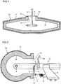
- [FIG. 1] FIG. 1 is a schematic diagram of a state of a heating device in use according to the present embodiment when seen from above a torpedo car.
- [FIG. 2] FIG. 2 is a schematic diagram of the state of the heating device in use according to the present embodiment when seen from a lateral side of the torpedo car.
- [FIG. 3] FIG. 3 is a front view illustrating a shape of a lid of the heating device according to the present embodiment.
- [FIG. 4] FIG. 4 is a schematic diagram of a state of a heating device in use according to another embodiment when seen from a lateral side of the torpedo car.
- [FIG. 5] FIG. 5 is a schematic diagram of a state of a heating device in use according to still another embodiment when seen from a lateral side of the torpedo car.
- [FIG. 6] FIG. 6 is a front view illustrating a shape of a lid of the heating device according to another embodiment.
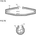
- [FIGs. 7] FIGs. 7 are views each illustrating positions of thermocouples in Example, where (a) illustrates a longitudinal direction of the torpedo car, and (b) illustrates a direction perpendicular to the longitudinal direction.
[Embodiments for Carrying out the Invention]
-
Hereinafter, embodiments of the present invention are explained with reference to the drawings. Incidentally, redundant description is avoided as for elements each having substantially the same functional constitution by supplying the same reference numerals in the present specification and the drawings.
-
FIG. 1 to FIG. 3 are views explaining a heating device according to an embodiment of the present invention, where FIG. 1 is a view when seen from above a torpedo car 10, FIG. 2 is a view when seen from a lateral side of the torpedo car 10, and FIG. 3 is a view when seen from a front of the torpedo car 10. As illustrated in FIG. 1, the torpedo car 10 includes a torpedo car main body 11 in an approximately long cylindrical shape which accommodates molten iron produced in a shaft furnace. The torpedo car main body 11 has a structure turnable around a major axis. A refractory 12 is installed on an inner wall of the torpedo car main body 11, and a mouth 13 for taking in and out the molten iron is provided at a center part in a longitudinal direction. In this embodiment, when a heating device 1 is used for drying and preheating works before the molten iron is received, the torpedo car main body 11 is firstly turned in such a manner that the mouth 13 of the torpedo car 10 is located at a lateral side of the torpedo car main body 11 and the mouth 13 faces approximately a vertical direction.
-
The heating device 1 includes a burner 2 and a lid 4 which is fixed to the burner 2 through an intermediary of a support bracket 3. Various burners except a regenerative burner can be used as the burner 2, and for example, as illustrated in FIG. 1, a tip is branched in left-and-right both sides and nozzles are faced both sides in a longitudinal direction of the torpedo car 10. The burner 2 is mounted on a cart 5 which can horizontally move as, for example, illustrated in FIG. 2, and able to move on a horizontal track. In this embodiment, since the lid 4 is fixed to the burner 2, the lid 4 is attached to a position of the mouth 13 at the same time when the burner 2 is inserted into an inside of the torpedo car 10. Note that the lid 4 may be fixed to a structural portion of the heating device 1 other than the burner 2. In this specification, a longitudinal direction of the torpedo car main body 11 is set as a left-right direction, and a direction orthogonal to the left-right direction on a horizontal plane is set as a front-rear direction (the torpedo car 10 side is a front side).
-
The lid 4 shuts off a part of the mouth 13 in a side view when the mouth 13 is seen from the front in order to obtain an open area ratio in accordance with a state at the heating time with respect to an opening area of the mouth 13. When the open area ratio in the side view is too small, discharge cannot be fully performed and an exhaust gas flow velocity from the opening part increases due to increase in an internal pressure, resulting in an increase in a facility load, and a predetermined fuel from the burner 2 does not flow to cause a shortage of combustion. When the open area ratio is too large, heating efficiency decreases and temperature becomes nonuniform due to entering of the outside air. An optimal value may be set as the open area ratio in accordance with a volume capacity of the torpedo car 10, the opening area of the mouth 13, specifications of the burner 2, heating conditions, and the like, but it is preferable to set the optimal value in accordance with particularly a gas flow rate which is discharged from the torpedo car 10 when the inside of the torpedo car 10 is heated. For example, in this embodiment, the open area ratio is set to be 10% to 80% of an opening area where a cross-sectional area of the burner 2 is excluded from the opening area of the mouth 13. In this embodiment, entering of the outside air is prevented and the opening area to discharge the exhaust gas is simultaneously secured by decreasing the opening area of the mouth 13 with the lid 4.
-
The lid 4 is attached to cover a lower side of the mouth 13 which faces approximately the vertical direction. When the lid 4 is disposed at an upper part of the mouth 13, exhaust gas is discharged while being in contact with a rear surface of the lid 4 resulting in frequent contacts between the high-temperature exhaust gas and the lid 4 to cause thermal deformation or the like of the lid 4 due to large effect of the heat load. Meanwhile, the lower side is less affected by the exhaust gas. In this embodiment, a shape of the lid 4 is a half-moon shape where a part of a center part of the mouth 13 where the burner 2 is inserted is cut-off from approximately a semicircle as illustrated in FIG. 3.
-
As illustrated in FIG. 2, an upper part of the lid 4 is fixed to the burner 2 through an intermediary of the support bracket 3. A lower part of the lid 4 is coupled to the cart 5 through an intermediary of a spring 6 having elasticity in the front-rear direction. The spring 6 is fixed to the cart 5 and has elasticity in a direction pushing the lower part of the lid 4 toward the torpedo car 10 side. The spring 6 is attached at two positions of the lid 4 through an intermediary of lower brackets 7 provided at left and right two positions at the lower part of the lid 4. Further, a refractory 8 having elasticity such as, for example, a ceramic rope is attached at a part which is in contact with a peripheral part 14 of the mouth 13 on a rear surface of the lid 4, that is, a surface on the mouth 13 side. Projecting and recessed shapes of the refractory 12 which is installed in the torpedo car 10 are different due to effect of adherents every time when the torpedo car is repeatedly used and projections and recessions of the peripheral part 14 also change, and therefore, a desired open area ratio is obtained by pushing the lower part of the lid 4 with an elastic body (spring 6) toward the mouth 13 side, and absorbing the projecting and recessed shape of the peripheral part 14 to eliminate gaps with the peripheral part 14 of the mouth 13 by providing the refractory 8. The refractory 8 is attached at least to a part which is in contact with around a lower end part of the peripheral part 14 or may be attached to a whole outer periphery of the lid 4 as illustrated in FIG. 3.
-
A window 21 to visually check the inside of the torpedo car 10 may be provided at the lid 4. Further, a flame-shielding plate 22 may be provided around the upper part of the mouth 13 with a proper distance from the mouth 13 as illustrated in FIG. 2.
-
A using method of the above-stated heating device 1 is explained.
-
After the refractory 12 of the inside of the torpedo car 10 is re-installed, the torpedo car main body 11 is turned in such a manner that the mouth 13 formed at the center of the torpedo car main body 11 is located at the lateral side of the torpedo car main body 11 and the mouth 13 faces approximately the vertical direction. The heating device 1 is disposed to oppose to the mouth 13, the burner 2 and the lid 4 are slid toward the mouth 13 by moving the cart 5, and the burner 2 is inserted into the inside of the torpedo car 10 from the mouth 13. At this time, the lid 4 is pushed on the mouth 13 side by the spring 6, and the refractory 8 having elasticity which is attached to the rear surface of the lid 4 is brought into contact with the peripheral part 14 of the mouth 13, and thereby, the lid 4 is attached without any gap while corresponding to the projections and recessions of the peripheral part 14.
-
After that, the refractory 12 installed on the inner wall surface over both end parts in a length direction of the torpedo car main body 11 is dried and preheated with the burner 2 from the center part where the mouth 13 is formed, and thereby, the exhaust gas is discharged from the opening at the upper side while suppressing entering of the outside air with the lid 4 at the lower part.
-
As mentioned above, according to this embodiment, the lid 4 which secures an exit of the exhaust gas while suppressing the entering of the outside air is provided at the heating time of the inside of the torpedo car 10, resulting in that highly-efficient and uniform heating is enabled. It is possible to reduce fuel, shorten a preheating time, and reduce cost owing to the increase in heating efficiency.
-
In the above-stated embodiment, an upper-end part and a lower-end part of the lid 4 are preferably respectively fixed with, for example, turnable pins 31, 32 as illustrated in FIG. 4 so as to be able to adjust an attachment angle. In FIG. 4, the cart 5 is not illustrated. In such a case, the lid 4 can be tilted from the vertical direction because the upper-end part of the lid 4 turns with the pin 31, and the lower-end part of the lid 4 turns with the pin 32. It is thereby possible to attach the lid 4 in accordance with an angle of the mouth 13 even when the mouth 13 does not face the strict vertical direction.
-
The open area ratio of the mouth 13 is desirably made adjustable in accordance with a heating state because amounts of exhaust gas or the like are different between, for example, the drying time and the preheating time after the refractory 12 of the torpedo car 10 is maintained. For example, the open area ratio is preferably set to 10% to 50% at the drying time because a flow rate of combustion gas (COG amount) is small and a flow rate of the exhaust gas is small. Meanwhile, the open area ratio is preferably set to 30% to 80% at the preheating time because the flow rate of the exhaust gas is large.
-
As an adjustment method of the open area ratio, for example, as illustrated in FIG. 5 and FIG. 6, the lid 4 is divided into an upper lid 4a and a lower lid 4b, and an opening degree may be adjusted by turning the lower lid 4b with respect to the upper lid 4a. In FIG. 5, the cart 5 is not illustrated. The spring 6 is provided at the lower lid 4b as same as the above, and the lower lid 4b is pushed toward the torpedo car 10 side by this spring 6 to partially cover the lower part of the mouth 13. The upper lid 4a and the lower lid 4b are connected with joint parts 41 such as, for example, hinges at a boundary thereof. A moving mechanism 42 which moves the upper lid 4a in the front-rear direction is provided at the upper lid 4a. The upper lid 4a is thereby constituted to be able to turn around the boundary between the upper lid 4a and the lower lid 4b, that is, to turn around a lower end of the upper lid 4a. In such a case, a maximum open area ratio of the mouth 13 becomes 80% when the mouth 13 is covered only with the lower lid 4b, and a minimum open area ratio of the mouth 13 becomes 10% when the mouth 13 is covered with a whole of the upper lid 4a and the lower lid 4b. Concretely, for example, when the upper lid 4a covers 70% of the mouth 13, and the lower lid 4b covers 10% of the mouth 13, the open area ratio of the mouth 13 can be adjusted within a range of 10% to 80% by these upper lid 4a and lower lid 4b. The refractory 8 is attached to each of the rear surface of the upper lid 4a and the rear surface of the lower lid 4b.
-
The adjustment method of the open area ratio is not limited to the above-stated method. For example, a position of an upper end of the lid 4 is set to be movable in the front-rear direction to make the attachment angle of the lid 4 with respect to the mouth 13 variable, and the opening degree may be adjusted by moving the upper end of the lid 4 toward a rear side when the open area ratio is made to be increased.
-
Here, according to the method disclosed in Patent Document 2, the shielding plate is attached to the mouth by opening the upper part for approximately 10 mm, but this 10 mm is uniform and the shielding plate is fixed. That is, Patent Document 2 does not disclose or suggest to adjust the open area ratio of the mouth 13 like this embodiment. Meanwhile, flexibility of the heating device 1 can be remarkably improved by making the open area ratio of the mouth 13 adjustable like this embodiment.
-
Though a preferred embodiment of the present invention has been explained hereinabove, the present invention is not limited to such examples. It should be understood that various changes and modifications are readily apparent to those skilled in the art within the scope of the spirit as set forth in claims, and those should also be covered by the technical scope of the present invention.
[Example]
-
The lid 4 as illustrated in FIG. 1 to FIG. 3 was provided at the lower side of the mouth 13 of the torpedo car 10, and drying and preheating of the inside of the torpedo car 10 were performed as Example of the present invention. In addition, drying and preheating of the inside of the torpedo car 10 were performed while opening the mouth 13 without providing any lid as Comparative Example.
-
In each of Example of the present invention and Comparative Example, a volume capacity of the torpedo car 10 was 60 m3 (molten iron: 300 ton), an opening area of the mouth 13 was 1.17 m2, a cross-sectional area of the burner 2 was 0.23 m2. A size of the lid 4 was changed to each of 0.75 m2, 0.47 m2, and 0.19 m2 to change the open area ratio of the mouth 13 covered with the lid 4 except the burner 2 to 80%, 50%, and 20%.
-
In each of Example of the present invention and Comparative Example, as illustrated in
FIGs. 7(a), (b), thermocouples No. 1, No. 2, and No. 3 were provided at three positions in the
torpedo car 10 to measure the temperature at the heating time. The thermocouple No. 1 was located at an end part in the longitudinal direction of the
torpedo car 10, the thermocouple No. 2 and the thermocouple No. 3 were each located near the
mouth 13 in the longitudinal direction to have different depth distances from the
mouth 13. The temperature and an oxygen concentration at each position were measured regarding a drying time after 15 hours had passed and a preheating time after 30 hours had passed since a heating start time. Results when the open area ratio was 80% were listed in Table 1, results when the open area ratio was 50% were listed in Table 2, and results when the open area ratio was 20% were listed in Table 3.
[Table 1] | <OPEN AREA RATIO 80%> |
| | TARGET TEMPERATURE | No.1 | No.2 | No.3 | MAXIMUM TEMPERATURE DIFFERENCE | OXYGEN CONCENTRATION |
| EXAMPLE OF PRESENT INVENTION | DRYING TIME(15hr) | 360°C | 251°C | 265°C | 285°C | 109°C | 14.4% |
| PREHEATING TIME(30hr) | 700°C | 694°C | 672°C | 679°C | 28°C | 0.4% |
| COMPARATIVE EXAMPLE | DRYING TIME(15hr) | 360°C | 178°C | 217°C | 247°C | 182°C | 15.2% |
| PREHEATING TIME(30hr) | 700°C | 628°C | 598°C | 701°C | 102°C | 7.5% |
[Table 2] | <OPEN AREA RATIO 50%> |
| | TARGET TEMPERATURE | No.1 | No.2 | No.3 | MAXIMUM TEMPERATURE DIFFERENCE | OXYGEN CONCENTRATION |
| EXAMPLE OF PRESENT INVENTION | DRYING TIME(15hr) | 360°C | 360°C | 346°C | 355°C | 14°C | 13.1% |
| PREHEATING TIME(30hr) | 700°C | 695°C | 674°C | 682°C | 26°C | 0.1% |
| COMPARATIVE EXAMPLE | DRYING TIME(15hr) | 360°C | 178°C | 217°C | 247°C | 182°C | 15.2% |
| PREHEATING TIME(30hr) | 700°C | 628°C | 598°C | 701°C | 102°C | 7.5% |
[Table 3] | <OPEN AREA RATIO 20%> |
| | TARGET TEMPERATURE | No.1 | No.2 | No.3 | MAXIMUM TEMPERATURE DIFFERENCE | OXYGEN CONCENTRATION |
| EXAMPLE OF PRESENT INVENTION | DRYING TIME(15hr) | 360°C | 355°C | 360°C | 356°C | 5°C | 12.5% |
| PREHEATING TIME(30hr) | 700°C | 690°C | 674°C | 678°C | 26°C | 0.2% |
| COMPARATIVE EXAMPLE | DRYING TIME(15hr) | 360°C | 178°C | 217°C | 247°C | 182°C | 15.2% |
| PREHEATING TIME(30hr) | 700°C | 628°C | 598°C | 701°C | 102°C | 7.5% |
-
It could be verified that the temperature in the torpedo car was uniformly increased in Example of the present invention compared to Comparative Example in each of the cases when the open area ratios were 20% to 80%. The oxygen concentration of Example of the present invention was lower than Comparative Example, and it could be verified that entering of the air could be suppressed. Regarding a total COG amount, energy saving of about 15% could be attained. Meanwhile, when the open area ratio was further decreased to 10%, an exhaust gas flow velocity from the opening part was increased and the facility load was increased due to the increase in the internal pressure. Further, the continuous measurement was impossible due to fuel shortage because a predetermined fuel does not flow from the burner 2.
[Industrial Applicability]
-
The present invention can be applied as a heating device when an inside of a torpedo car is heated with a burner and is useful when heating is performed by using a burner other than a regenerative burner.
[Explanation of Codes]
-
- 1
- heating device
- 2
- burner
- 3
- support bracket
- 4
- lid
- 5
- cart
- 6
- spring
- 7
- lower bracket
- 8
- refractory
- 10
- torpedo car
- 11
- torpedo car main body
- 12
- refractory
- 13
- mouth
- 14
- peripheral part
- 21
- window
- 22
- shielding plate
- 31, 32
- pin
- 41
- joint part
- 42
- moving mechanism