EP3575151A1 - Center console structure and vehicle - Google Patents
Center console structure and vehicle Download PDFInfo
- Publication number
- EP3575151A1 EP3575151A1 EP19177316.7A EP19177316A EP3575151A1 EP 3575151 A1 EP3575151 A1 EP 3575151A1 EP 19177316 A EP19177316 A EP 19177316A EP 3575151 A1 EP3575151 A1 EP 3575151A1
- Authority
- EP
- European Patent Office
- Prior art keywords
- center console
- vehicle
- instrument panel
- engagement
- extension
- Prior art date
- Legal status (The legal status is an assumption and is not a legal conclusion. Google has not performed a legal analysis and makes no representation as to the accuracy of the status listed.)
- Withdrawn
Links
Images


Classifications
-
- B—PERFORMING OPERATIONS; TRANSPORTING
- B60—VEHICLES IN GENERAL
- B60K—ARRANGEMENT OR MOUNTING OF PROPULSION UNITS OR OF TRANSMISSIONS IN VEHICLES; ARRANGEMENT OR MOUNTING OF PLURAL DIVERSE PRIME-MOVERS IN VEHICLES; AUXILIARY DRIVES FOR VEHICLES; INSTRUMENTATION OR DASHBOARDS FOR VEHICLES; ARRANGEMENTS IN CONNECTION WITH COOLING, AIR INTAKE, GAS EXHAUST OR FUEL SUPPLY OF PROPULSION UNITS IN VEHICLES
- B60K20/00—Arrangement or mounting of change-speed gearing control devices in vehicles
- B60K20/02—Arrangement or mounting of change-speed gearing control devices in vehicles of initiating means
-
- B—PERFORMING OPERATIONS; TRANSPORTING
- B60—VEHICLES IN GENERAL
- B60K—ARRANGEMENT OR MOUNTING OF PROPULSION UNITS OR OF TRANSMISSIONS IN VEHICLES; ARRANGEMENT OR MOUNTING OF PLURAL DIVERSE PRIME-MOVERS IN VEHICLES; AUXILIARY DRIVES FOR VEHICLES; INSTRUMENTATION OR DASHBOARDS FOR VEHICLES; ARRANGEMENTS IN CONNECTION WITH COOLING, AIR INTAKE, GAS EXHAUST OR FUEL SUPPLY OF PROPULSION UNITS IN VEHICLES
- B60K35/00—Instruments specially adapted for vehicles; Arrangement of instruments in or on vehicles
- B60K35/20—Output arrangements, i.e. from vehicle to user, associated with vehicle functions or specially adapted therefor
- B60K35/21—Output arrangements, i.e. from vehicle to user, associated with vehicle functions or specially adapted therefor using visual output, e.g. blinking lights or matrix displays
- B60K35/22—Display screens
-
- B—PERFORMING OPERATIONS; TRANSPORTING
- B60—VEHICLES IN GENERAL
- B60K—ARRANGEMENT OR MOUNTING OF PROPULSION UNITS OR OF TRANSMISSIONS IN VEHICLES; ARRANGEMENT OR MOUNTING OF PLURAL DIVERSE PRIME-MOVERS IN VEHICLES; AUXILIARY DRIVES FOR VEHICLES; INSTRUMENTATION OR DASHBOARDS FOR VEHICLES; ARRANGEMENTS IN CONNECTION WITH COOLING, AIR INTAKE, GAS EXHAUST OR FUEL SUPPLY OF PROPULSION UNITS IN VEHICLES
- B60K35/00—Instruments specially adapted for vehicles; Arrangement of instruments in or on vehicles
- B60K35/60—Instruments characterised by their location or relative disposition in or on vehicles
-
- B—PERFORMING OPERATIONS; TRANSPORTING
- B60—VEHICLES IN GENERAL
- B60K—ARRANGEMENT OR MOUNTING OF PROPULSION UNITS OR OF TRANSMISSIONS IN VEHICLES; ARRANGEMENT OR MOUNTING OF PLURAL DIVERSE PRIME-MOVERS IN VEHICLES; AUXILIARY DRIVES FOR VEHICLES; INSTRUMENTATION OR DASHBOARDS FOR VEHICLES; ARRANGEMENTS IN CONNECTION WITH COOLING, AIR INTAKE, GAS EXHAUST OR FUEL SUPPLY OF PROPULSION UNITS IN VEHICLES
- B60K37/00—Dashboards
- B60K37/20—Dashboard panels
-
- B—PERFORMING OPERATIONS; TRANSPORTING
- B60—VEHICLES IN GENERAL
- B60R—VEHICLES, VEHICLE FITTINGS, OR VEHICLE PARTS, NOT OTHERWISE PROVIDED FOR
- B60R11/00—Arrangements for holding or mounting articles, not otherwise provided for
- B60R11/02—Arrangements for holding or mounting articles, not otherwise provided for for radio sets, television sets, telephones, or the like; Arrangement of controls thereof
- B60R11/0229—Arrangements for holding or mounting articles, not otherwise provided for for radio sets, television sets, telephones, or the like; Arrangement of controls thereof for displays, e.g. cathodic tubes
-
- B—PERFORMING OPERATIONS; TRANSPORTING
- B60—VEHICLES IN GENERAL
- B60R—VEHICLES, VEHICLE FITTINGS, OR VEHICLE PARTS, NOT OTHERWISE PROVIDED FOR
- B60R7/00—Stowing or holding appliances inside vehicle primarily intended for personal property smaller than suit-cases, e.g. travelling articles, or maps
- B60R7/04—Stowing or holding appliances inside vehicle primarily intended for personal property smaller than suit-cases, e.g. travelling articles, or maps in driver or passenger space, e.g. using racks
-
- B—PERFORMING OPERATIONS; TRANSPORTING
- B60—VEHICLES IN GENERAL
- B60K—ARRANGEMENT OR MOUNTING OF PROPULSION UNITS OR OF TRANSMISSIONS IN VEHICLES; ARRANGEMENT OR MOUNTING OF PLURAL DIVERSE PRIME-MOVERS IN VEHICLES; AUXILIARY DRIVES FOR VEHICLES; INSTRUMENTATION OR DASHBOARDS FOR VEHICLES; ARRANGEMENTS IN CONNECTION WITH COOLING, AIR INTAKE, GAS EXHAUST OR FUEL SUPPLY OF PROPULSION UNITS IN VEHICLES
- B60K2360/00—Indexing scheme associated with groups B60K35/00 or B60K37/00 relating to details of instruments or dashboards
- B60K2360/77—Instrument locations other than the dashboard
- B60K2360/774—Instrument locations other than the dashboard on or in the centre console
-
- B—PERFORMING OPERATIONS; TRANSPORTING
- B60—VEHICLES IN GENERAL
- B60R—VEHICLES, VEHICLE FITTINGS, OR VEHICLE PARTS, NOT OTHERWISE PROVIDED FOR
- B60R11/00—Arrangements for holding or mounting articles, not otherwise provided for
- B60R2011/0001—Arrangements for holding or mounting articles, not otherwise provided for characterised by position
- B60R2011/0003—Arrangements for holding or mounting articles, not otherwise provided for characterised by position inside the vehicle
- B60R2011/0007—Mid-console
Definitions
- the present invention relates to a center console structure and a vehicle, particularly a center console structure that is disposed between a driver seat and a passenger seat and has a shift operation mechanism thereon.
- a transmission operation mechanism is provided on the upper surface of a center console and this transmission operation mechanism is coupled to a transmission via a link member and the like.
- the space below the center console in which the link member described above has been conventionally disposed can be used as a storage or a design element.
- patent document 1 discloses a center console structure that has a space for an operation panel in a position above the center console and behind an instrument panel provided in a vehicle interior and has a display device on the rising surface of the operation panel.
- patent document 2 discloses a center console structure in which a rear console member is provided behind a console member extending along a floor surface in a front-rear direction of a vehicle, an arm rest member is provided above this rear console member, the instrument panel is coupled to the preceding part of the arm rest member by a bridge-shaped shift panel, and a shift knob of a shift operation part is disposed on the shift panel.
- patent documents 1 and 2 described above do not disclose the addition of visual floating feeling to the upper body of the center console.
- an object of the invention is to add visual floating feeling to the upper body of the center console.
- a center console structure is provided.
- the center console structure is to be disposed between a driver seat and a passenger seat and has a shift operation mechanism thereon.
- the center console structure includes:
- the upper body extends forward of the columnar part like a cantilever.
- the upper body has, in a front part thereof, an extension part that is bent and configured to rise forward and obliquely upward.
- a surface part of the extension part to be faced to a sitting occupant is configured to form an outer surface continuous with the center console surface.
- a front portion of the extension part in the front-rear direction of the vehicle is to be locked to a rear projecting part of an instrument panel.
- a display device configured to display vehicle-related information is to be accommodated in the extension part.
- a display surface is disposed in the surface part to be faced to the sitting occupant.
- a first engagement part is provided in a front portion of the extension part in the front-rear direction of the vehicle.
- a second engagement part to be engaged with the first engagement part is provided in the rear projecting part of the instrument panel.
- a space through which the first engagement part and the second engagement part are accessed from above for engagement is provided between an upper front edge part of the extension part and the rear projecting part of the instrument panel.
- a vehicle includes : a driver seat; a passenger seat; a floor surface between the driver seat and the passenger seat; an instrument panel; and the above center console structure.
- the vehicle further includes a display device.
- a center console structure that is disposed between a driver seat and a passenger seat and has a shift operation mechanism thereon, the center console structure including a columnar part erected on a vehicle interior floor surface between the driver seat and the passenger seat, the columnar part extending upward to vicinity of cushion surfaces of the seats; and an upper body that is disposed above the columnar part, extends in a front-rear direction, has an upper part forming a center console surface, and accommodates the shift operation mechanism, in which the upper body extends forward of the columnar part like a cantilever, has, in a front part thereof, an extension part that is bent and then rises forward and obliquely upward, a surface part of the extension part close to a sitting occupant forms an outer surface continuous with the center console surface and a portion of the extension part close to a front of the vehicle is locked to a rear projecting part of an instrument panel.
- the visual floating feeling of the upper body can be provided for the occupant by terminating the extension part of the upper body of the center console in the proximity of the rear projecting part of the instrument panel.
- the supporting strength of the upper body described above can be obtained even when the upper body is shaped like a cantilever by locking the portion of the extension part close to the front of the vehicle to the rear projecting part of the instrument panel.
- a display device that displays vehicle-related information is accommodated in the extension part and a display surface is disposed in the surface part close to the sitting occupant.
- the display device which is originally provided in the instrument panel, in the extension part that rises forward and obliquely upward of the center console, the display device can be disposed close to the occupant, the visibility of the display surface is improved, and the instrument panel can be simplified.
- a first engagement part is provided in a portion of the extension part close to the front of the vehicle, a second engagement part to be engaged with the first engagement part is provided in a rear projecting part of the instrument panel, and a space through which the first engagement part and the second engagement part are accessed from above for engagement is provided between an upper front edge part of the extension part and the rear projecting part of the instrument panel.
- the invention has the effect of adding visual floating feeling to the upper body of the center console.
- a center console structure that is disposed between a driver seat and a passenger seat and has a shift operation mechanism thereon, the center console structure including a columnar part erected on a vehicle interior floor surface between the driver seat and the passenger seat, the columnar part extending upward to vicinity of cushion surfaces of the seats; and an upper body that is disposed above the columnar part, extends in a front-rear direction, has an upper part forming a center console surface, and accommodates the shift operation mechanism, in which the upper body extends forward of the columnar part like a cantilever, has, in a front part thereof, an extension part that is bent and then rises forward and obliquely upward, a surface part of the extension part close to a sitting occupant forms an outer surface continuous with the center console surface and a portion of the extension part close to a front of the vehicle is locked to a rear projecting part of an instrument panel.
- a tunnel part 5 extending in the front-rear direction of the vehicle while jutting to the vehicle interior is formed integrally or approximately integrally with the floor panel 2 in the middle part in the vehicle width direction of the floor panel 2 described above.
- the tunnel part 5 is formed so as to extend in the front-rear direction of the vehicle between the dash lower panel 1 and a kick-up part 6 in the rear part.
- a driver seat 7 and a passenger seat 8 as front seats are provided to the left and the right of the floor panel 2 described above.
- the driver seat 7 includes a seat cushion 7C that forms a seating surface for an occupant, a seat back 7B that forms a backrest for the occupant, and a head rest 7H that holds the head of the occupant.
- the passenger seat 8 also includes a seat cushion 8C that forms a seating surface for an occupant, a seat back 8B that forms a backrest for the occupant, and a head rest 8H that holds the head of the occupant.
- the passenger seat 8 described above is provided via a seat slide rail 11 including a lower rail 9 and an upper rail 10 and a seat frame 12 and the position of the passenger seat 8 in the front-rear direction of the vehicle can be adjusted according to the physique of the occupant in the passenger seat.
- the driver seat 7 is also provided via a seat slide rail including a lower rail and an upper rail and a seat frame and the position of the driver seat 7 in the front-rear direction of the vehicle can be adjusted according to the physique of the occupant in the driver seat.
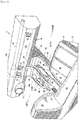
- reference numeral 13 represents a front window glass and reference numeral 14 represents an instrument panel.
- the instrument panel 14 has an upper surface part 14a extending substantially in the front-rear direction, a rear surface part 14b extending downward and forward from the rear end of this upper surface part 14a, and a lower surface part 14c extending from the lower end of this rear surface part 14b toward the front of the vehicle and a steering column cover 15 is provided in a part of the instrument panel 14 close to the driver seat 7.
- an instrument panel member 16 as a strengthening member that extends in the vehicle width direction and couples left and right hinge pillars is provided inside the instrument panel 14 described above.
- a part of this instrument panel member 16 close to the driver seat 7 has a larger diameter than a part of this instrument panel member 16 close to the passenger seat 8 as illustrated in Fig. 1 to prevent the occupants from offset collision.
- a support stay 17 runs between the instrument panel member 16 described above and the tunnel part 5 so that this single support stay 17 supports the instrument panel member 16.
- a defroster blowout port 19 communicating with a defroster duct 18 is opened in a part of the instrument panel 14 facing a slant lower part of the front window glass 13 so as to prevent the fogging of the front window glass 13.
- a center vent blowout port 21 and a side vent blowout port 22 that communicate with a vent duct 20 are opened and formed in parts of the instrument panel 14 that face the face parts of the occupants.
- foot blowout ports 24 that communicate with a foot duct (so-called heat duct) 23 are opened and formed in parts of the instrument panel 14 that face the foot spaces for the occupants sitting in the driver seat 7 and the passenger seat 8.
- Fig. 6 is a side view illustrating a center console
- Fig. 7 is a perspective view illustrating an internal frame
- Fig. 8 is an enlarged side view illustrating a main part in Fig. 4
- Fig. 9 is an enlarged side view illustrating a main part in Fig. 5
- Fig. 10 is a cross sectional view illustrating a main part seen from arrow A-A in Fig. 1
- Fig. 11 is a cross sectional view illustrating a main part seen from arrow B-B in Fig. 4
- Fig. 12(a) is a cross sectional view illustrating a bottom part taken along line C-C in Fig. 6
- Fig. 12(b) is a cross sectional view illustrating a main part seen from arrow D-D in Fig. 6 .
- a center console body 30 is erected on the upper surface of the tunnel part 5 as the floor surface (vehicle interior floor surface) between the driver seat 7 and the passenger seat 8, has a shift operation mechanism 25 thereon, and extends in the front-rear direction from a position immediately below the instrument panel 14 to the side parts of the seat cushions 7C and 8C of the left and right seats 7 and 8.
- This center console body 30 includes an internal frame 40 (see Fig. 7 ), made of metal, that supports the shift operation mechanism 25, an outer sheath body 50, made of resin, that encloses the internal frame 40 and forms a dressed surface, and a bottom part console 60 as the bottom part positioned in front of a base part member (see a base part bracket 41 in Fig. 7 ), which will be described later, and extends in the front-rear direction of the vehicle to a position immediately below the instrument panel 14 (see Fig. 6 ).
- the internal frame 40 made of metal includes the base part bracket 41 as the base part member having a hat-shaped cross section in the vehicle width direction, a lower bracket 43 formed by bending a metal plate like a rectangular column and welding and fixing necessary portions at welded parts 42, a middle bracket 44 fixed to an upper part of the lower bracket 43, and an upper bracket 45 fixed to an upper part of the middle bracket 44 and having a substantially concave cross section in the vehicle width direction and an upper member 46 is formed by the elements (that is, the lower bracket 43, the middle bracket 44, and the upper bracket 45) disposed above the base part bracket 41.
- the front side part of the internal frame 40 is slanted so that the upper member 46 (particularly, the upper bracket 45) is positioned forward and obliquely upward of the base part bracket 41 close to the floor surface.
- the base part bracket 41 described above is mounted and supported on the upper surface of the tunnel part 5 by mount rubbers 47 and mounting members 48 such as bolts and nuts.
- the upper bracket 45 is fixed to the middle bracket 44 by mounting members 49 such as bolts and nuts.
- the outer sheath body 50 made of resin described above includes left and right side wall parts 51 and 51, substantially reverse U-shaped left and right fence parts 51a and 51a (see Fig. 12(b) ) formed by extending the lower parts of the left and right side wall parts 51 forward, and a front lower part 51b that couples the inner end parts of the left and right fence parts 51a and 51a in the vehicle width direction.
- the bottom part console 60 for which the cross sectional shape is illustrated in Fig. 12 (a) is formed by integrally forming a bottom wall 61, inside walls 62 that rise upward from the left and right ends of the bottom wall 61, upper walls 63 that extend outward in the vehicle width direction from the upper ends of the inside walls 62, and outside walls 64 that extend downward from the outer end parts in the vehicle width direction of the upper walls 63 using synthetic resin and the shapes of the walls 62, 63, and 64 described above correspond to the shapes of the left and right fence parts 51a and 51a of the outer sheath body 50.
- both left and right sides of the bottom part console 60 are surrounded by the left and right fence parts 51a of the outer sheath body 50 and the rear part is surrounded by the front lower part 51b of the outer sheath body 50.
- a storage part 70 is formed so that both left and right sides above the left and right fence parts 51a described above and both left and right sides above the upper walls 63 of the bottom part console 60 described above are opened to foot spaces for the driver seat 7 and the passenger seat 8 and the foot spaces communicate with each other through the storage part 70.
- the center console structure in the embodiment is erected on the tunnel part 5, which is the vehicle interior floor surface between the driver seat 7 and the passenger seat 8, and has a columnar part X that extends upward to the vicinity of the upper surfaces of the seat cushions 7C and 8C of the seats 7 and 8 and an upper body Y that is disposed above the columnar part X, extends in the front-rear direction, has the upper surface part forming a center console surface Z, and accommodates the shift operation mechanism 25 (see Fig. 6 ).
- the columnar part X described above includes the base part bracket 41, the lower bracket 43, and the side wall parts 51, which are a lower area part of the outer sheath body 50, illustrated in Fig. 11 .
- the upper body Y described above includes the middle bracket 44, the upper bracket 45, and an upper area part of the outer sheath body 50 described later, illustrated in Fig. 11 .
- the upper body Y described above is extended forward of the columnar part X described above like a cantilever and has, in the front part thereof, an extension part 31 that is bent and then rises forward and obliquely upward.
- extension part 31 is formed so as to rise at approximately 60 degrees with respect to a virtual extension line of the center console surface Z toward the front of the vehicle in the embodiment, the invention is not limited to this value.
- the upper body Y described above includes an upper panel 52 that forms the center console surface Z and side panels 53 positioned on both left and right sides of the upper panel 52. These panels 52 and 53 constitute an outer sheath body, made of resin, that forms a dressed surface.
- the upper panel 52 described above extends in the front-rear direction of the vehicle to form the center console surface Z and integrally forms a slant surface 52a that is bent and then rises forward and obliquely upward from the front end to form a surface part of the extension part 31 close to the sitting occupant, so that the surface part of the extension part 31 close to the sitting occupant forms an outer surface continuous with the center console surface Z.
- the side panels 53 described above extend in the front-rear direction of the vehicle to form the side walls of the center console surface Z and integrally form rising surfaces 53a that are bent and then rise forward and obliquely upward from the front ends to form the side parts of the extension part 31.
- the upper panel 52 described above integrally forms a folded surface 52b that is folded downward and backward from the upper end of the slant surface 52a to form the front surface of the extension part 31.
- the side panels 53 described above integrally form a front part 53b through which the front ends of the pair of left and right side panels 53 are coupled to each other in the vehicle width direction to form the front wall of the upper body Y.
- panels 54 for ornament are provided so as to include the rising surfaces 53a of the side panels 53 along both left and right sides of the side panels 53 described above.
- step sections 51c which are the upper ends of the side wall parts 51, are disposed via middle panels 55 on the outsides in the vehicle width direction of the left and right along panels 54.
- the step sections 51c are formed so as to have steps on the inside in the vehicle width direction of the side wall parts 51.
- ornament panels 56 of a substantially parallelogram shape are attached to the surfaces on the outsides in the vehicle width direction of the step sections 51c.
- spacers 57 extending in the front-rear direction are disposed in the upper end parts of the middle panels 55 described above.
- the spacers 57 are formed to have gate-shaped cross sections.
- a shift knob 25a of the shift operation mechanism 25 is disposed immediately above the rear of the storage part 70 described above.
- the shift operation mechanism 25 includes the shift knob 25a, a shift rod 25b, and a pivot part 25c, the pivot part 25c and the shift rod 25b are accommodated in the internal space of the upper body Y, and the shift knob 25a is disposed above the center console surface Z so as to enable a shift operation.
- the shift rod 25b is guided by shift guides 26 and 27 supported by the upper bracket 45.
- a knob part 29 of a commander 28 a knob part 81 of a volume control device 80 (so-called volume) for an in-vehicle audio apparatus or the like, and a parking brake operating part 82 are provided on the center console surface Z behind the shift knob 25a described above.
- the commander 28 described above is a device that selects an application section, an Internet section, a communication section, a navigation section, or a setting section by rotating the knob part 29 thereof and determines the option by pushing the knob part 29.
- the application section has fuel economy information, various kinds of maintenance information, and the like
- the Internet section has an Internet radio, a portable audio, an AM/FM radio, a CD/DVD player, and the like
- the communication section has a hands-free call, reading of a short message, and the like
- the navigation section has road map display, route navigation, route guidance, and the like
- the setting section has the setting of sound, the adjustment of the brightness and the angle of an active driving display, and the like.
- an upper bracket 32 as a first engagement part is provided on the folded surface 52b of the upper panel 52 as a vehicle front portion of the extension part 31
- a lower bracket 33 as a second engagement part to be engaged with the upper bracket 32 is provided in the rear projecting part 14d of the instrument panel 14
- a nut 34 is connected to the lower surface of the lower bracket 33 in advance, and a space G through which the brackets 32 and 33 are accessed from above is provided between the upward front edge part of the extension part 31 and the rear projecting part 14d of the instrument panel 14.
- extension part 31 is disposed close to the rear projecting part 14d of the instrument panel 14 so that the upper bracket 32 close to the extension part 31 is placed on the lower bracket 33 close to the instrument panel 14, a bolt 35 is moved downward through the space G described above to tighten the bolt 35 into the nut 34 described above, the portion of the extension part 31 close to the vehicle front is thereby locked to the rear projecting part 14d of the instrument panel 14 via the brackets 32 and 33.
- the positions in the up-down direction of the brackets 32 and 33 described above are set in an invisible part spaced downward a predetermined distance from the upper end of the extension part 31 so that the sitting occupant cannot see the head of the bolt 35.
- the extension part 31 accommodates a display device 36 for an air conditioner as an example of the display device that displays vehicle-related information and a display surface 37 of the display device 36 is disposed in a surface part (see the slant surface 52a) close to the sitting occupant.
- the extension part 31 accommodates a display device 36 for an air conditioner as an example of the display device for displaying vehicle-related information and a display surface 37 of the display device 36 is disposed in the side surface part (see the slant surface 52a) of the sitting occupant.
- the display device 36 including the display surface 37 described above is configured by a touch panel type display device and the display device 36 is configured so that the sitting occupant can see the entire display surface 37 even when the shift knob 25a is shifted to the most front position (parking position) as illustrated in Fig. 10 .
- a storage space 71 is formed between the upper body Y including the center console surface Z and the tunnel part 5 as the floor surface and the upper part of the storage space 71 is separated by the upper body Y, the lower part thereof is separated by the bottom wall 61 (see Fig. 12 (a) ) and the front lower part 51b (see Fig. 12 (b) ) as the floor surfaces, the rear part thereof is separated by the columnar part X described above, and both left and right sides thereof are separated by the side walls 62 and 64 that are wall parts lower than the upper surfaces of the seat cushions 7C and 8C.
- a bulge part 38 that accommodates the shift rod 25b and the pivot part 25c, which are lower parts of the shift operation mechanism 25, is formed on the side of the lower surface of the middle in the vehicle width direction of the upper body Y, and, as illustrated in Fig. 8 and Fig. 9 , a front edge 38a of the bulge part 38 described above is positioned closer to the front of the vehicle than a front edge Xa of the columnar part X that is the rear edge of the input or output a right and left side take in/out opening of the storage space 71 described above in side view of the vehicle.
- slanted walls 65 and 66 which are left and right wall parts extending forward and obliquely upward, are formed integrally with the side walls 62 and 64 of the bottom part console 60.
- the rear end part of the slanted wall 65 is a front edge 65a of the storage space 71.
- the rear end part of the slanted wall 66 is a front edge 66a of the storage space 71.
- the front edge Xa of the columnar part X, the front edge 38a of the bulge part 38, and the front edges 65a and 66a of the left and right wall parts of the storage space 71 are formed as shapes that are slanted upward toward the front and have the same slanted angle.
- reference numeral 67 represents a kneepad member in Fig. 8 .
- the lower front side of the columnar part X and the wall parts (that is, the inside walls 62, the upper walls 63, the outside walls 64) of the bottom part console 60 are the outer sheath body and formed so that the left and right outer surfaces are flush with each other.
- the inside walls 62, the upper walls 63, and the outside walls 64 described above are the outer sheath body and, as illustrated in Fig. 12 , formed so that the front lower part 51b of the columnar part X is flush with the bottom wall 61 of the bottom part console 60 and the fence parts 51a of the columnar part X are flush with the walls 62, 63, and 64 of the bottom part console 60.
- fence parts 51a and the front lower part 51b described above are formed integrally with the side wall parts 51 included in the outer sheath body 50.
- a parting line PL that divides the outer sheath body into the front and rear parts in the wall parts (see the elements 61, 62, 63, 64, 51a, and 51b) is provided.
- a stepped-down part 68 corresponding to the thickness of the fence parts 51a and the front lower part 51b described above is integrally formed and the fence parts 51a and the front lower part 51b described above are disposed on this stepped-down part 68 to ensure the flush structure of the outer sheath body.
- a plurality of clips 51d projecting inward is formed integrally and the outside parts of the fence parts 51a are fitted to the outside walls 64 close to the bottom part console 60 illustrated in Fig. 12 by the clips 51d.
- a front side cup holder 72 as a second storage space is provided behind the columnar part X described above
- a rear side cup holder 73 as a third storage space is provided behind the front side cup holder 72
- an arm rest part 74 also functioning as an open/close lid for the rear side cup holder 73 is provided above the rear side cup holder 73
- reference numeral 90 represents a bag as an example of a baggage placed so as to be easily transferred to or from the storage part 70.
- arrow F in the drawing represents the front side of the vehicle
- arrow R represents the rear side of the vehicle
- arrow LEFT represents the left side of the vehicle width direction
- arrow RIGHT represents the right side of the vehicle width direction
- arrow UP represents the upper side of the vehicle.
- the center console structure is a center console structure that is disposed between the driver seat 7 and the passenger seat 8 and has the shift operation mechanism 25 thereon and includes the columnar part X that is erected on the vehicle interior floor surface (see the tunnel part 5) between the driver seat 7 and the passenger seat 8 and extends upward to the vicinity of the cushion surfaces (see the upper surfaces of the seat cushions 7C and 8C) of the seats 7 and 8 and the upper body Y that is disposed above the columnar part X, extends in the front-rear direction, has the upper surface part forming the center console surface Z, and accommodates the shift operation mechanism 25, in which the upper body Y extends forward of the columnar part X like a cantilever and has, in the front part thereof, the extension part 31 that is bent and then rises forward and obliquely upward, the surface part of the extension part 31 close to the sitting occupant forms an outer surface continuous with the center console surface Z, and the portion of the extension part 31 close to the front of the vehicle is locked to the
- the visual floating feeling of the upper body Y can be provided for the occupant by terminating the extension part 31 of the upper body Y of the center console in the proximity of the rear projecting part 14d of the instrument panel 14.
- the supporting strength of the upper body Y described above can be obtained even when the upper body Y is shaped like a cantilever by locking the portion of the extension part 31 close to the front of the vehicle to the rear projecting part 14d of the instrument panel 14.
- the display device 36 that displays vehicle-related information is accommodated in the extension part 31 described above and the display surface 37 is disposed in the surface part close to the sitting occupant (see Fig. 10 ).
- the display device 36 can be disposed close to the occupant, the visibility of the display surface 37 is improved, the instrument panel 14 can be simplified, and application to the display device 36 of a touch panel type also becomes effective.
- the first engagement part (see the upper bracket 32) is provided in a portion of the extension part 31 close to the front of the vehicle and the second engagement part (see the lower bracket 33) to be engaged with the first engagement part (the upper bracket 32) is provided in the rear projecting part 14d of the instrument panel 14, and the space G through which the first engagement part and the second engagement part (see the brackets 32 and 33) are accessed from above for engagement is provided between the upper front edge part of the extension part 31 and the rear projecting part 14d of the instrument panel 14 (see Fig. 10 ).
- first engagement part (the upper bracket 32) close to the extension part 31 can be surely engaged with the second engagement part (the lower bracket 33) close to the instrument panel 14 and engagement work for both engagement parts (see the brackets 32 and 33) can be performed by access through the space G described above, the workability thereof can be improved.
- the vehicle interior floor surface in the invention corresponds to the tunnel part 5 in the embodiment.
- the first engagement part corresponds to the upper bracket 32 and the second engagement part corresponds to the lower bracket 33, but the invention is not limited to only the structure of the embodiment described above.
- center console structure is applied to a left-hand drive vehicle in the embodiment described above, the center console structure according to the invention may be applied to a right-hand drive vehicle.
- the invention is useful for a center console structure that is disposed between a driver seat and a passenger seat and has a shift operation mechanism thereon.
Landscapes
- Engineering & Computer Science (AREA)
- Mechanical Engineering (AREA)
- Chemical & Material Sciences (AREA)
- Combustion & Propulsion (AREA)
- Transportation (AREA)
- Vehicle Step Arrangements And Article Storage (AREA)
- Fittings On The Vehicle Exterior For Carrying Loads, And Devices For Holding Or Mounting Articles (AREA)
Abstract
Description
- The present invention relates to a center console structure and a vehicle, particularly a center console structure that is disposed between a driver seat and a passenger seat and has a shift operation mechanism thereon.
- Generally, a transmission operation mechanism is provided on the upper surface of a center console and this transmission operation mechanism is coupled to a transmission via a link member and the like.
- In recent years, the transmission operation mechanism (shift operation mechanism) described above and a parking brake have been electronically achieved. When the transmission operation mechanism and the parking brake are electronically achieved as described above, since a transmission operation and braking are performed by electronic signals instead of a conventional mechanical coupling structure using a link member and the like, the link member described above becomes unnecessary.
- Accordingly, the space below the center console in which the link member described above has been conventionally disposed can be used as a storage or a design element.
- By the way,
patent document 1 discloses a center console structure that has a space for an operation panel in a position above the center console and behind an instrument panel provided in a vehicle interior and has a display device on the rising surface of the operation panel. - In addition,
patent document 2 discloses a center console structure in which a rear console member is provided behind a console member extending along a floor surface in a front-rear direction of a vehicle, an arm rest member is provided above this rear console member, the instrument panel is coupled to the preceding part of the arm rest member by a bridge-shaped shift panel, and a shift knob of a shift operation part is disposed on the shift panel. - However,
patent documents -
- [Patent document 1]
JP-A-2013-237286 - [Patent document 2]
JP-A-2010-076607 - Accordingly, an object of the invention is to add visual floating feeling to the upper body of the center console.
- According to the invention, a center console structure is provided. The center console structure is to be disposed between a driver seat and a passenger seat and has a shift operation mechanism thereon. The center console structure includes:
- a columnar part to be erected on a vehicle interior floor surface between the driver seat and the passenger seat, the columnar part being configured to extending upward to vicinity of cushion surfaces of the seats; and
- an upper body that is disposed above the columnar part, is configured to extends in a front-rear direction, has an upper part forming a center console surface, and is configured to accommodates the shift operation mechanism.
- The upper body extends forward of the columnar part like a cantilever. The upper body has, in a front part thereof, an extension part that is bent and configured to rise forward and obliquely upward. A surface part of the extension part to be faced to a sitting occupant is configured to form an outer surface continuous with the center console surface. A front portion of the extension part in the front-rear direction of the vehicle is to be locked to a rear projecting part of an instrument panel.
- Particularly, a display device configured to display vehicle-related information is to be accommodated in the extension part. A display surface is disposed in the surface part to be faced to the sitting occupant.
- Further particularly, a first engagement part is provided in a front portion of the extension part in the front-rear direction of the vehicle. A second engagement part to be engaged with the first engagement part is provided in the rear projecting part of the instrument panel. A space through which the first engagement part and the second engagement part are accessed from above for engagement is provided between an upper front edge part of the extension part and the rear projecting part of the instrument panel.
- Further particularly, a vehicle includes : a driver seat; a passenger seat; a floor surface between the driver seat and the passenger seat; an instrument panel; and the above center console structure.
- Further particularly, the vehicle further includes a display device.
- According to the invention, there is provided a center console structure that is disposed between a driver seat and a passenger seat and has a shift operation mechanism thereon, the center console structure including a columnar part erected on a vehicle interior floor surface between the driver seat and the passenger seat, the columnar part extending upward to vicinity of cushion surfaces of the seats; and an upper body that is disposed above the columnar part, extends in a front-rear direction, has an upper part forming a center console surface, and accommodates the shift operation mechanism, in which the upper body extends forward of the columnar part like a cantilever, has, in a front part thereof, an extension part that is bent and then rises forward and obliquely upward, a surface part of the extension part close to a sitting occupant forms an outer surface continuous with the center console surface and a portion of the extension part close to a front of the vehicle is locked to a rear projecting part of an instrument panel.
- In the structure described above, the visual floating feeling of the upper body can be provided for the occupant by terminating the extension part of the upper body of the center console in the proximity of the rear projecting part of the instrument panel. On the other hand, the supporting strength of the upper body described above can be obtained even when the upper body is shaped like a cantilever by locking the portion of the extension part close to the front of the vehicle to the rear projecting part of the instrument panel.
- In one aspect of the invention, a display device that displays vehicle-related information is accommodated in the extension part and a display surface is disposed in the surface part close to the sitting occupant.
- In this structure, by providing the display device, which is originally provided in the instrument panel, in the extension part that rises forward and obliquely upward of the center console, the display device can be disposed close to the occupant, the visibility of the display surface is improved, and the instrument panel can be simplified.
- In one aspect of the invention, a first engagement part is provided in a portion of the extension part close to the front of the vehicle, a second engagement part to be engaged with the first engagement part is provided in a rear projecting part of the instrument panel, and a space through which the first engagement part and the second engagement part are accessed from above for engagement is provided between an upper front edge part of the extension part and the rear projecting part of the instrument panel.
- In this structure, since the first engagement part close to the extension part can be surely engaged with the second engagement part close to the instrument panel and engagement work for both engagement parts can be performed by access through the space described above, the workability thereof can be improved. In addition, since the front end part (front end side of the extension part) of the upper body seems to the sitting occupant to float in the rear projecting part of the instrument panel due to the space described above, visual floating feeling can be improved.
- The invention has the effect of adding visual floating feeling to the upper body of the center console.
-
-
Fig. 1 is a plan view illustrating a center console structure according to the invention. -
Fig. 2 is a perspective view illustrating the center console structure seen from oblique upper left of a vehicle. -
Fig. 3 is a perspective view illustrating the center console structure seen from oblique upper right of the vehicle. -
Fig. 4 is a side view illustrating the center console structure seen from the left side of the vehicle. -
Fig. 5 is a side view illustrating the center console structure seen from the right side of the vehicle. -
Fig. 6 is a side view illustrating a center console. -
Fig. 7 is a perspective view illustrating an internal frame. -
Fig. 8 is an enlarged side view illustrating a main part inFig. 4 . -
Fig. 9 is an enlarged side view illustrating a main part inFig. 5 . -
Fig. 10 is a cross sectional view illustrating a main part seen along arrows A-A inFig. 1 . -
Fig. 11 is a cross sectional view illustrating a main part seen along arrows B-B inFig. 4 . -
Fig. 12(a) is a cross sectional view illustrating a bottom part taken along line C-C inFig. 6 andFig. 12(b) is a cross sectional view illustrating a main part seen along arrows D-D inFig. 6 . - The addition of visual floating feeling to an upper body of a center console is achieved by a center console structure that is disposed between a driver seat and a passenger seat and has a shift operation mechanism thereon, the center console structure including a columnar part erected on a vehicle interior floor surface between the driver seat and the passenger seat, the columnar part extending upward to vicinity of cushion surfaces of the seats; and an upper body that is disposed above the columnar part, extends in a front-rear direction, has an upper part forming a center console surface, and accommodates the shift operation mechanism, in which the upper body extends forward of the columnar part like a cantilever, has, in a front part thereof, an extension part that is bent and then rises forward and obliquely upward, a surface part of the extension part close to a sitting occupant forms an outer surface continuous with the center console surface and a portion of the extension part close to a front of the vehicle is locked to a rear projecting part of an instrument panel.
- A
tunnel part 5 extending in the front-rear direction of the vehicle while jutting to the vehicle interior is formed integrally or approximately integrally with thefloor panel 2 in the middle part in the vehicle width direction of thefloor panel 2 described above. In this embodiment, thetunnel part 5 is formed so as to extend in the front-rear direction of the vehicle between the dashlower panel 1 and a kick-uppart 6 in the rear part. - As illustrated in
Fig. 1 , adriver seat 7 and apassenger seat 8 as front seats are provided to the left and the right of thefloor panel 2 described above. - The
driver seat 7 includes a seat cushion 7C that forms a seating surface for an occupant, aseat back 7B that forms a backrest for the occupant, and ahead rest 7H that holds the head of the occupant. - Similarly, the
passenger seat 8 also includes aseat cushion 8C that forms a seating surface for an occupant, aseat back 8B that forms a backrest for the occupant, and ahead rest 8H that holds the head of the occupant. - As illustrated in
Fig. 4 andFig. 5 , thepassenger seat 8 described above is provided via aseat slide rail 11 including alower rail 9 and anupper rail 10 and aseat frame 12 and the position of thepassenger seat 8 in the front-rear direction of the vehicle can be adjusted according to the physique of the occupant in the passenger seat. - As in the
passenger seat 8, thedriver seat 7 is also provided via a seat slide rail including a lower rail and an upper rail and a seat frame and the position of thedriver seat 7 in the front-rear direction of the vehicle can be adjusted according to the physique of the occupant in the driver seat. - In
Fig. 4 andFig. 5 ,reference numeral 13 represents a front window glass andreference numeral 14 represents an instrument panel. - As illustrated in these drawings, the
instrument panel 14 has anupper surface part 14a extending substantially in the front-rear direction, arear surface part 14b extending downward and forward from the rear end of thisupper surface part 14a, and alower surface part 14c extending from the lower end of thisrear surface part 14b toward the front of the vehicle and asteering column cover 15 is provided in a part of theinstrument panel 14 close to thedriver seat 7. - As illustrated in
Fig. 1 to Fig. 5 , aninstrument panel member 16 as a strengthening member that extends in the vehicle width direction and couples left and right hinge pillars is provided inside theinstrument panel 14 described above. In theinstrument panel member 16, a part of thisinstrument panel member 16 close to thedriver seat 7 has a larger diameter than a part of thisinstrument panel member 16 close to thepassenger seat 8 as illustrated inFig. 1 to prevent the occupants from offset collision. In addition, as illustrated inFig. 1 , asupport stay 17 runs between theinstrument panel member 16 described above and thetunnel part 5 so that thissingle support stay 17 supports theinstrument panel member 16. - As illustrated in
Fig. 4 , adefroster blowout port 19 communicating with adefroster duct 18 is opened in a part of theinstrument panel 14 facing a slant lower part of thefront window glass 13 so as to prevent the fogging of thefront window glass 13. - As illustrated in
Fig. 2 andFig. 4 , a centervent blowout port 21 and a sidevent blowout port 22 that communicate with avent duct 20 are opened and formed in parts of theinstrument panel 14 that face the face parts of the occupants. - As illustrated in
Fig. 4 ,foot blowout ports 24 that communicate with a foot duct (so-called heat duct) 23 are opened and formed in parts of theinstrument panel 14 that face the foot spaces for the occupants sitting in thedriver seat 7 and thepassenger seat 8. -
Fig. 6 is a side view illustrating a center console,Fig. 7 is a perspective view illustrating an internal frame,Fig. 8 is an enlarged side view illustrating a main part inFig. 4 ,Fig. 9 is an enlarged side view illustrating a main part inFig. 5 ,Fig. 10 is a cross sectional view illustrating a main part seen from arrow A-A inFig. 1 ,Fig. 11 is a cross sectional view illustrating a main part seen from arrow B-B inFig. 4 ,Fig. 12(a) is a cross sectional view illustrating a bottom part taken along line C-C inFig. 6 , andFig. 12(b) is a cross sectional view illustrating a main part seen from arrow D-D inFig. 6 . - As illustrated in
Fig. 1 andFig. 6 , acenter console body 30 is erected on the upper surface of thetunnel part 5 as the floor surface (vehicle interior floor surface) between thedriver seat 7 and thepassenger seat 8, has ashift operation mechanism 25 thereon, and extends in the front-rear direction from a position immediately below theinstrument panel 14 to the side parts of the seat cushions 7C and 8C of the left andright seats - This
center console body 30 includes an internal frame 40 (seeFig. 7 ), made of metal, that supports theshift operation mechanism 25, anouter sheath body 50, made of resin, that encloses theinternal frame 40 and forms a dressed surface, and abottom part console 60 as the bottom part positioned in front of a base part member (see abase part bracket 41 inFig. 7 ), which will be described later, and extends in the front-rear direction of the vehicle to a position immediately below the instrument panel 14 (seeFig. 6 ). - As illustrated in
Fig. 7 , theinternal frame 40 made of metal includes thebase part bracket 41 as the base part member having a hat-shaped cross section in the vehicle width direction, alower bracket 43 formed by bending a metal plate like a rectangular column and welding and fixing necessary portions at weldedparts 42, amiddle bracket 44 fixed to an upper part of thelower bracket 43, and anupper bracket 45 fixed to an upper part of themiddle bracket 44 and having a substantially concave cross section in the vehicle width direction and anupper member 46 is formed by the elements (that is, thelower bracket 43, themiddle bracket 44, and the upper bracket 45) disposed above thebase part bracket 41. - As illustrated in
Fig. 6 andFig. 7 , the front side part of theinternal frame 40 is slanted so that the upper member 46 (particularly, the upper bracket 45) is positioned forward and obliquely upward of thebase part bracket 41 close to the floor surface. - Here, as illustrated in
Fig. 11 , thebase part bracket 41 described above is mounted and supported on the upper surface of thetunnel part 5 bymount rubbers 47 and mountingmembers 48 such as bolts and nuts. In addition, as illustrated in this drawing, theupper bracket 45 is fixed to themiddle bracket 44 by mountingmembers 49 such as bolts and nuts. - As illustrated in
Fig. 6 andFig. 11 , theouter sheath body 50 made of resin described above includes left and rightside wall parts right fence parts Fig. 12(b) ) formed by extending the lower parts of the left and rightside wall parts 51 forward, and a frontlower part 51b that couples the inner end parts of the left andright fence parts - On the other hand, the
bottom part console 60 for which the cross sectional shape is illustrated inFig. 12 (a) is formed by integrally forming abottom wall 61, insidewalls 62 that rise upward from the left and right ends of thebottom wall 61,upper walls 63 that extend outward in the vehicle width direction from the upper ends of theinside walls 62, andoutside walls 64 that extend downward from the outer end parts in the vehicle width direction of theupper walls 63 using synthetic resin and the shapes of thewalls right fence parts outer sheath body 50. - In addition, as illustrated in
Fig. 6 , both left and right sides of thebottom part console 60 are surrounded by the left andright fence parts 51a of theouter sheath body 50 and the rear part is surrounded by the frontlower part 51b of theouter sheath body 50. - In addition, as illustrated in
Fig. 6 , astorage part 70 is formed so that both left and right sides above the left andright fence parts 51a described above and both left and right sides above theupper walls 63 of thebottom part console 60 described above are opened to foot spaces for thedriver seat 7 and thepassenger seat 8 and the foot spaces communicate with each other through thestorage part 70. - By the way, the center console structure in the embodiment is erected on the
tunnel part 5, which is the vehicle interior floor surface between thedriver seat 7 and thepassenger seat 8, and has
a columnar part X that extends upward to the vicinity of the upper surfaces of the seat cushions 7C and 8C of theseats Fig. 6 ). - The columnar part X described above includes the
base part bracket 41, thelower bracket 43, and theside wall parts 51, which are a lower area part of theouter sheath body 50, illustrated inFig. 11 . - In addition, the upper body Y described above includes the
middle bracket 44, theupper bracket 45, and an upper area part of theouter sheath body 50 described later, illustrated inFig. 11 . - As illustrated in
Fig. 6 andFig. 8 toFig. 10 , the upper body Y described above is extended forward of the columnar part X described above like a cantilever and has, in the front part thereof, anextension part 31 that is bent and then rises forward and obliquely upward. - Although the
extension part 31 is formed so as to rise at approximately 60 degrees with respect to a virtual extension line of the center console surface Z toward the front of the vehicle in the embodiment, the invention is not limited to this value. - As illustrated in
Fig. 11 , the upper body Y described above includes anupper panel 52 that forms the center console surface Z andside panels 53 positioned on both left and right sides of theupper panel 52. Thesepanels - The
upper panel 52 described above extends in the front-rear direction of the vehicle to form the center console surface Z and integrally forms aslant surface 52a that is bent and then rises forward and obliquely upward from the front end to form a surface part of theextension part 31 close to the sitting occupant, so that the surface part of theextension part 31 close to the sitting occupant forms an outer surface continuous with the center console surface Z. - In addition, the
side panels 53 described above extend in the front-rear direction of the vehicle to form the side walls of the center console surface Z and integrally form risingsurfaces 53a that are bent and then rise forward and obliquely upward from the front ends to form the side parts of theextension part 31. - In addition, as illustrated in
Fig. 10 , theupper panel 52 described above integrally forms a foldedsurface 52b that is folded downward and backward from the upper end of theslant surface 52a to form the front surface of theextension part 31. In addition, theside panels 53 described above integrally form afront part 53b through which the front ends of the pair of left andright side panels 53 are coupled to each other in the vehicle width direction to form the front wall of the upper body Y. - As illustrated in
Fig. 11 , alongpanels 54 for ornament are provided so as to include the risingsurfaces 53a of theside panels 53 along both left and right sides of theside panels 53 described above. - In addition,
step sections 51c, which are the upper ends of theside wall parts 51, are disposed viamiddle panels 55 on the outsides in the vehicle width direction of the left and right alongpanels 54. Thestep sections 51c are formed so as to have steps on the inside in the vehicle width direction of theside wall parts 51. - In addition,
ornament panels 56 of a substantially parallelogram shape are attached to the surfaces on the outsides in the vehicle width direction of thestep sections 51c. In addition, as illustrated inFig. 11 ,spacers 57 extending in the front-rear direction are disposed in the upper end parts of themiddle panels 55 described above. Thespacers 57 are formed to have gate-shaped cross sections. - On the other hand, as illustrated in
Fig. 6 andFig. 10 , ashift knob 25a of theshift operation mechanism 25 is disposed immediately above the rear of thestorage part 70 described above. - As illustrated in
Fig. 10 , theshift operation mechanism 25 includes theshift knob 25a, ashift rod 25b, and apivot part 25c, thepivot part 25c and theshift rod 25b are accommodated in the internal space of the upper body Y, and theshift knob 25a is disposed above the center console surface Z so as to enable a shift operation. In addition, theshift rod 25b is guided by shift guides 26 and 27 supported by theupper bracket 45. - As illustrated in
Fig. 2 ,Fig. 3 , andFig. 10 , aknob part 29 of acommander 28, aknob part 81 of a volume control device 80 (so-called volume) for an in-vehicle audio apparatus or the like, and a parkingbrake operating part 82 are provided on the center console surface Z behind theshift knob 25a described above. - The
commander 28 described above is a device that selects an application section, an Internet section, a communication section, a navigation section, or a setting section by rotating theknob part 29 thereof and determines the option by pushing theknob part 29. - As for the options of each of the sections described above, the application section has fuel economy information, various kinds of maintenance information, and the like, the Internet section has an Internet radio, a portable audio, an AM/FM radio, a CD/DVD player, and the like, the communication section has a hands-free call, reading of a short message, and the like, the navigation section has road map display, route navigation, route guidance, and the like, and the setting section has the setting of sound, the adjustment of the brightness and the angle of an active driving display, and the like.
- By the way, as illustrated in
Fig. 10 , a portion of theextension part 31 close to the front of the vehicle is locked to arear projecting part 14d of theinstrument panel 14. - Specifically, as illustrated in this drawing, an
upper bracket 32 as a first engagement part is provided on the foldedsurface 52b of theupper panel 52 as a vehicle front portion of theextension part 31, alower bracket 33 as a second engagement part to be engaged with theupper bracket 32 is provided in therear projecting part 14d of theinstrument panel 14, anut 34 is connected to the lower surface of thelower bracket 33 in advance, and a space G through which thebrackets extension part 31 and therear projecting part 14d of theinstrument panel 14. - In addition, the
extension part 31 is disposed close to therear projecting part 14d of theinstrument panel 14 so that theupper bracket 32 close to theextension part 31 is placed on thelower bracket 33 close to theinstrument panel 14, abolt 35 is moved downward through the space G described above to tighten thebolt 35 into thenut 34 described above, the portion of theextension part 31 close to the vehicle front is thereby locked to therear projecting part 14d of theinstrument panel 14 via thebrackets - Here, the positions in the up-down direction of the
brackets extension part 31 so that the sitting occupant cannot see the head of thebolt 35. - In addition, as illustrated in
Fig. 10 , theextension part 31 accommodates adisplay device 36 for an air conditioner as an example of the display device that displays vehicle-related information and adisplay surface 37 of thedisplay device 36 is disposed in a surface part (see theslant surface 52a) close to the sitting occupant. - In addition, as illustrated in
Fig. 10 , theextension part 31 accommodates adisplay device 36 for an air conditioner as an example of the display device for displaying vehicle-related information and adisplay surface 37 of thedisplay device 36 is disposed in the side surface part (see theslant surface 52a) of the sitting occupant. - In the embodiment, the
display device 36 including thedisplay surface 37 described above is configured by a touch panel type display device and thedisplay device 36 is configured so that the sitting occupant can see theentire display surface 37 even when theshift knob 25a is shifted to the most front position (parking position) as illustrated inFig. 10 . - As illustrated in
Fig. 8 andFig. 9 , astorage space 71 is formed between the upper body Y including the center console surface Z and thetunnel part 5 as the floor surface and the upper part of thestorage space 71 is separated by the upper body Y, the lower part thereof is separated by the bottom wall 61 (seeFig. 12 (a) ) and the frontlower part 51b (seeFig. 12 (b) ) as the floor surfaces, the rear part thereof is separated by the columnar part X described above, and both left and right sides thereof are separated by theside walls - As illustrated in
Fig. 10 , the upper body Y described above projects forward of the columnar part X until the upper body Y reaches therear projecting part 14d of theinstrument panel 14, abulge part 38 that accommodates theshift rod 25b and thepivot part 25c, which are lower parts of theshift operation mechanism 25, is formed on the side of the lower surface of the middle in the vehicle width direction of the upper body Y, and, as illustrated inFig. 8 andFig. 9 , afront edge 38a of thebulge part 38 described above is positioned closer to the front of the vehicle than a front edge Xa of the columnar part X that is the rear edge of the input or output a right and left side take in/out opening of thestorage space 71 described above in side view of the vehicle. - In
Fig. 8 andFig. 9 , slantedwalls side walls bottom part console 60. - On the left side of the vehicle, as illustrated in
Fig. 8 , the rear end part of the slantedwall 65 is afront edge 65a of thestorage space 71. On the right side of the vehicle, as illustrated inFig. 9 , the rear end part of the slantedwall 66 is afront edge 66a of thestorage space 71. - Accordingly, in the embodiment, the front edge Xa of the columnar part X, the
front edge 38a of thebulge part 38, and thefront edges storage space 71 are formed as shapes that are slanted upward toward the front and have the same slanted angle. It should be noted here thatreference numeral 67 represents a kneepad member inFig. 8 . - In addition, as illustrated in
Fig. 8 andFig. 9 , the lower front side of the columnar part X and the wall parts (that is, theinside walls 62, theupper walls 63, the outside walls 64) of thebottom part console 60 are the outer sheath body and formed so that the left and right outer surfaces are flush with each other. - Specifically, the
inside walls 62, theupper walls 63, and theoutside walls 64 described above are the outer sheath body and, as illustrated inFig. 12 , formed so that the frontlower part 51b of the columnar part X is flush with thebottom wall 61 of thebottom part console 60 and thefence parts 51a of the columnar part X are flush with thewalls bottom part console 60. - Here, the
fence parts 51a and the frontlower part 51b described above are formed integrally with theside wall parts 51 included in theouter sheath body 50. - In addition, as illustrated in
Fig. 8 andFig. 9 , a parting line PL that divides the outer sheath body into the front and rear parts in the wall parts (see theelements - In the embodiment, as illustrated in
Fig. 8 andFig. 9 , in the rear end part of thebottom part console 60, a stepped-downpart 68 corresponding to the thickness of thefence parts 51a and the frontlower part 51b described above is integrally formed and thefence parts 51a and the frontlower part 51b described above are disposed on this stepped-downpart 68 to ensure the flush structure of the outer sheath body. - In addition, as illustrated in
Fig. 12 (b) , on the outer side parts of thefence parts 51a of theside wall part 51 close to the columnar part X, a plurality ofclips 51d projecting inward is formed integrally and the outside parts of thefence parts 51a are fitted to theoutside walls 64 close to thebottom part console 60 illustrated inFig. 12 by theclips 51d. - On the other hand, as illustrated in
Fig. 6 , a frontside cup holder 72 as a second storage space is provided behind the columnar part X described above, a rearside cup holder 73 as a third storage space is provided behind the frontside cup holder 72, and anarm rest part 74 also functioning as an open/close lid for the rearside cup holder 73 is provided above the rearside cup holder 73, - In
Fig. 9 ,reference numeral 90 represents a bag as an example of a baggage placed so as to be easily transferred to or from thestorage part 70. In addition, arrow F in the drawing represents the front side of the vehicle, arrow R represents the rear side of the vehicle, and arrow LEFT represents the left side of the vehicle width direction, arrow RIGHT represents the right side of the vehicle width direction, and arrow UP represents the upper side of the vehicle. - As described above, the center console structure according to the embodiment is a center console structure that is disposed between the
driver seat 7 and thepassenger seat 8 and has theshift operation mechanism 25 thereon and includes the columnar part X that is erected on the vehicle interior floor surface (see the tunnel part 5) between thedriver seat 7 and thepassenger seat 8 and extends upward to the vicinity of the cushion surfaces (see the upper surfaces of the seat cushions 7C and 8C) of theseats shift operation mechanism 25, in which the upper body Y extends forward of the columnar part X like a cantilever and has, in the front part thereof, theextension part 31 that is bent and then rises forward and obliquely upward, the surface part of theextension part 31 close to the sitting occupant forms an outer surface continuous with the center console surface Z, and the portion of theextension part 31 close to the front of the vehicle is locked to therear projecting part 14d of the instrument panel 14 (seeFig. 1 ,Fig. 4 ,Fig. 5 , andFig. 10 ). - In this structure, the visual floating feeling of the upper body Y can be provided for the occupant by terminating the
extension part 31 of the upper body Y of the center console in the proximity of therear projecting part 14d of theinstrument panel 14. On the other hand, the supporting strength of the upper body Y described above can be obtained even when the upper body Y is shaped like a cantilever by locking the portion of theextension part 31 close to the front of the vehicle to therear projecting part 14d of theinstrument panel 14. - In addition, in one embodiment of the invention, the
display device 36 that displays vehicle-related information is accommodated in theextension part 31 described above and thedisplay surface 37 is disposed in the surface part close to the sitting occupant (seeFig. 10 ). - In this structure, by providing the display device, which is originally provided in the
instrument panel 14, in theextension part 31 that rises forward and obliquely upward of the center console, thedisplay device 36 can be disposed close to the occupant, the visibility of thedisplay surface 37 is improved, theinstrument panel 14 can be simplified, and application to thedisplay device 36 of a touch panel type also becomes effective. - In addition, in one embodiment of the invention, the first engagement part (see the upper bracket 32) is provided in a portion of the
extension part 31 close to the front of the vehicle and the second engagement part (see the lower bracket 33) to be engaged with the first engagement part (the upper bracket 32) is provided in therear projecting part 14d of theinstrument panel 14, and the space G through which the first engagement part and the second engagement part (see thebrackets 32 and 33) are accessed from above for engagement is provided between the upper front edge part of theextension part 31 and therear projecting part 14d of the instrument panel 14 (seeFig. 10 ). - In this structure, since the first engagement part (the upper bracket 32) close to the
extension part 31 can be surely engaged with the second engagement part (the lower bracket 33) close to theinstrument panel 14 and engagement work for both engagement parts (see thebrackets 32 and 33) can be performed by access through the space G described above, the workability thereof can be improved. - In addition, since the front end part (see the front end part of the extension part 31) of the upper body Y seems to the sitting occupant to float in the
rear projecting part 14d of theinstrument panel 14 due to the space G described above, visual floating feeling can be improved. - In correspondence between the invention and the embodiment described above, the vehicle interior floor surface in the invention corresponds to the
tunnel part 5 in the embodiment. Similarly, the first engagement part corresponds to theupper bracket 32 and the second engagement part corresponds to thelower bracket 33, but the invention is not limited to only the structure of the embodiment described above. - For example, although the center console structure is applied to a left-hand drive vehicle in the embodiment described above, the center console structure according to the invention may be applied to a right-hand drive vehicle.
- As described above, the invention is useful for a center console structure that is disposed between a driver seat and a passenger seat and has a shift operation mechanism thereon.
-
- 5:
- tunnel part (vehicle interior floor surface)
- 7:
- driver seat
- 8:
- passenger seat
- 14:
- instrument panel
- 14d:
- rear projecting part
- 25:
- shift operation mechanism
- 31:
- extension part
- 32:
- upper bracket (first engagement part)
- 33:
- lower bracket (second engagement part)
- 36:
- display device
- 37:
- display surface
- G:
- space
- X:
- columnar part
- Y:
- upper body
- Z:
- center console surface
Claims (5)
- A center console structure that is to be disposed between a driver seat (7) and a passenger seat (8) and has a shift operation mechanism (25) thereon, the center console structure comprising:a columnar part (X) to be erected on a vehicle interior floor surface (5) between the driver seat (7) and the passenger seat (8), the columnar part (X) being configured to extend upward to vicinity of cushion surfaces of the seats (7, 8); andan upper body (Y) that is disposed above the columnar part (X), is configured to extend in a front-rear direction, has an upper part forming a center console surface (Z), and is configured to accommodate the shift operation mechanism (25),whereinthe upper body (Y) extends forward of the columnar part (X) like a cantilever,the upper body (Y) has, in a front part thereof, an extension part (31) that is bent and configured to rise forward and obliquely upward,a surface part of the extension part (31) to be faced to a sitting occupant is configured to form an outer surface continuous with the center console surface (Z), anda front portion of the extension part (31) in the front-rear direction of the vehicle is to be locked to a rear projecting part (14d) of an instrument panel (14).
- The center console structure according to claim 1,
wherein a display device (36) configured to display vehicle-related information is to be accommodated in the extension part (31) and a display surface (37) is disposed in the surface part to be faced to the sitting occupant. - The center console structure according to claim 1 or 2,
wherein a first engagement part (32) is provided in a front portion of the extension part (31) in the front-rear direction of the vehicle,
a second engagement part (33) to be engaged with the first engagement part (32) is provided in the rear projecting part (14d) of the instrument panel (14), and
a space through which the first engagement part (32) and the second engagement part (33) are accessed from above for engagement is provided between an upper front edge part of the extension part (31) and the rear projecting part (14d) of the instrument panel (14). - A vehicle comprising:a driver seat (7);a passenger seat (8);a floor surface (5) between the driver seat (7) and the passenger seat (8);an instrument panel (14); anda center console structure according to any one of the preceding claims.
- The vehicle according to claim 4, further comprising a display device (36).
Applications Claiming Priority (1)
| Application Number | Priority Date | Filing Date | Title |
|---|---|---|---|
| JP2018103223A JP7087680B2 (en) | 2018-05-30 | 2018-05-30 | Center console structure |
Publications (1)
| Publication Number | Publication Date |
|---|---|
| EP3575151A1 true EP3575151A1 (en) | 2019-12-04 |
Family
ID=66676393
Family Applications (1)
| Application Number | Title | Priority Date | Filing Date |
|---|---|---|---|
| EP19177316.7A Withdrawn EP3575151A1 (en) | 2018-05-30 | 2019-05-29 | Center console structure and vehicle |
Country Status (4)
| Country | Link |
|---|---|
| US (1) | US10981513B2 (en) |
| EP (1) | EP3575151A1 (en) |
| JP (1) | JP7087680B2 (en) |
| CN (1) | CN110549947B (en) |
Families Citing this family (6)
| Publication number | Priority date | Publication date | Assignee | Title |
|---|---|---|---|---|
| JP7167823B2 (en) * | 2019-04-04 | 2022-11-09 | 株式会社豊田自動織機 | console support structure |
| CN111942481B (en) * | 2019-05-15 | 2022-10-28 | 马自达汽车株式会社 | Lower body structure of vehicle |
| US11447199B2 (en) | 2020-02-21 | 2022-09-20 | Toyota Motor Engineering & Manufacturing North America, Inc. | Guard for vehicle blind spot monitor |
| JP7399927B2 (en) * | 2021-11-08 | 2023-12-18 | 本田技研工業株式会社 | vehicle center console |
| DE102023101140A1 (en) * | 2023-01-18 | 2024-07-18 | Bayerische Motoren Werke Aktiengesellschaft | Center console for a motor vehicle |
| FR3155480A1 (en) * | 2023-11-20 | 2025-05-23 | Stellantis Auto Sas | INTERFACE FOR JOINING A CENTRAL CONSOLE WITH A MOTOR VEHICLE DASHBOARD |
Citations (4)
| Publication number | Priority date | Publication date | Assignee | Title |
|---|---|---|---|---|
| JPS58194641A (en) * | 1982-05-10 | 1983-11-12 | Nissan Motor Co Ltd | Mounting structure for center console box |
| WO2010035542A1 (en) * | 2008-09-26 | 2010-04-01 | トヨタ車体株式会社 | Mounting structure for vehicle interior part |
| JP2013237286A (en) | 2012-05-11 | 2013-11-28 | Calsonic Kansei Corp | Control panel structure for vehicle |
| JP2014133503A (en) * | 2013-01-11 | 2014-07-24 | Honda Motor Co Ltd | Center console structure of vehicle |
Family Cites Families (17)
| Publication number | Priority date | Publication date | Assignee | Title |
|---|---|---|---|---|
| US4998770A (en) * | 1989-08-29 | 1991-03-12 | Suzuki Motor Corporation | Armrest for mounting on a console box |
| DE19820337C1 (en) * | 1998-05-07 | 1999-09-09 | Daimler Chrysler Ag | Cover for motor vehicle console |
| US6820926B2 (en) * | 2003-01-06 | 2004-11-23 | Mitsubishi Jidosha Kogyo Kabushiki Kaisha | Vehicle body reinforcement structure |
| US7513549B2 (en) * | 2006-01-06 | 2009-04-07 | Ford Global Technologies, Llc | Vehicle center console |
| US7370898B2 (en) * | 2006-06-26 | 2008-05-13 | International Automotive Components Group North America, Inc. | Console assembly for a vehicle |
| DE102006030476A1 (en) * | 2006-07-01 | 2008-01-03 | GM Global Technology Operations, Inc., Detroit | Center console for e.g. passenger car, has rails supported in holder with rail`s front ends for instrument panel of vehicle by two-part clamping unit, and two interconnected clamping unit parts of clamping unit are adjustable to each other |
| US7513550B1 (en) * | 2007-11-09 | 2009-04-07 | Toyota Motor Engineering & Manufacturing North America, Inc. | Vehicle console mounting bracket |
| JP2009262635A (en) * | 2008-04-22 | 2009-11-12 | Mazda Motor Corp | Instrument panel device |
| JP5176926B2 (en) | 2008-12-12 | 2013-04-03 | トヨタ車体株式会社 | Assembly structure of a vehicle front console module |
| CN105008178B (en) * | 2013-01-11 | 2017-07-14 | 江森自控科技公司 | Floor consoles for vehicles with removable storage compartments |
| WO2015155961A1 (en) * | 2014-04-07 | 2015-10-15 | パナソニックIpマネジメント株式会社 | Rear-view confirmation device and automobile equipped with same |
| KR102573705B1 (en) * | 2015-11-24 | 2023-09-04 | 삼성디스플레이 주식회사 | Display control system |
| US10035477B1 (en) * | 2017-01-11 | 2018-07-31 | Honda Motor Co., Ltd. | Cord management system, and methods of use and manufacture thereof |
| DE102017003688B4 (en) * | 2017-04-15 | 2020-04-23 | Audi Ag | Cockpit for a two-wheeler |
| US10189392B2 (en) * | 2017-05-08 | 2019-01-29 | Ford Global Technologies, Llc | Vehicle center console working surface |
| JP2019206279A (en) * | 2018-05-30 | 2019-12-05 | マツダ株式会社 | Center console structure |
| JP7064967B2 (en) * | 2018-06-05 | 2022-05-11 | トヨタ自動車東日本株式会社 | Rear console for automobiles |
-
2018
- 2018-05-30 JP JP2018103223A patent/JP7087680B2/en active Active
-
2019
- 2019-05-24 CN CN201910441002.7A patent/CN110549947B/en active Active
- 2019-05-29 EP EP19177316.7A patent/EP3575151A1/en not_active Withdrawn
- 2019-05-30 US US16/426,485 patent/US10981513B2/en active Active
Patent Citations (5)
| Publication number | Priority date | Publication date | Assignee | Title |
|---|---|---|---|---|
| JPS58194641A (en) * | 1982-05-10 | 1983-11-12 | Nissan Motor Co Ltd | Mounting structure for center console box |
| WO2010035542A1 (en) * | 2008-09-26 | 2010-04-01 | トヨタ車体株式会社 | Mounting structure for vehicle interior part |
| JP2010076607A (en) | 2008-09-26 | 2010-04-08 | Toyota Auto Body Co Ltd | Attachment structure of vehicular interior component |
| JP2013237286A (en) | 2012-05-11 | 2013-11-28 | Calsonic Kansei Corp | Control panel structure for vehicle |
| JP2014133503A (en) * | 2013-01-11 | 2014-07-24 | Honda Motor Co Ltd | Center console structure of vehicle |
Also Published As
| Publication number | Publication date |
|---|---|
| US10981513B2 (en) | 2021-04-20 |
| JP7087680B2 (en) | 2022-06-21 |
| CN110549947A (en) | 2019-12-10 |
| JP2019206280A (en) | 2019-12-05 |
| US20190366936A1 (en) | 2019-12-05 |
| CN110549947B (en) | 2023-07-04 |
Similar Documents
| Publication | Publication Date | Title |
|---|---|---|
| US10981513B2 (en) | Center console structure | |
| US7926845B2 (en) | Instrument panel for vehicle and method for attaching vehicle-mounted device to instrument panel for vehicle | |
| CN103802672B (en) | The installation constitution of infomation display device for vehicle | |
| EP3575150A1 (en) | Center console structure and vehicle | |
| JP5991237B2 (en) | Mounting structure for in-vehicle equipment | |
| JP5991238B2 (en) | Display unit mounting structure | |
| JP7119585B2 (en) | Center console structure | |
| JP4485992B2 (en) | Steering column mounting structure | |
| US12202549B2 (en) | Vehicle front part structure | |
| JP4547410B2 (en) | Steering hanger beam | |
| JP7534245B2 (en) | Instrument Panel | |
| JP7043975B2 (en) | Center console structure | |
| CN113071313A (en) | Instrument panel structure of vehicle | |
| JP4634485B2 (en) | Interior material mounting structure | |
| JP7043976B2 (en) | Center console structure | |
| KR20210004495A (en) | Cowl cross bar for vehicle | |
| JP4242327B2 (en) | Instrument panel structure for vehicles | |
| JP4159909B2 (en) | Box unit mounting structure | |
| JP2025027300A (en) | Instrument panel structure | |
| JPH10203215A (en) | Electronic device mounting structure for vehicle seats | |
| JP3196402B2 (en) | Audio device assembly structure | |
| JP2001219806A (en) | Car interior structure | |
| JPH0790783B2 (en) | Steering column support structure | |
| JPH0560962U (en) | Car airbag mounting structure | |
| JP2006056401A (en) | Vehicle front structure |
Legal Events
| Date | Code | Title | Description |
|---|---|---|---|
| PUAI | Public reference made under article 153(3) epc to a published international application that has entered the european phase |
Free format text: ORIGINAL CODE: 0009012 |
|
| STAA | Information on the status of an ep patent application or granted ep patent |
Free format text: STATUS: THE APPLICATION HAS BEEN PUBLISHED |
|
| AK | Designated contracting states |
Kind code of ref document: A1 Designated state(s): AL AT BE BG CH CY CZ DE DK EE ES FI FR GB GR HR HU IE IS IT LI LT LU LV MC MK MT NL NO PL PT RO RS SE SI SK SM TR |
|
| AX | Request for extension of the european patent |
Extension state: BA ME |
|
| STAA | Information on the status of an ep patent application or granted ep patent |
Free format text: STATUS: REQUEST FOR EXAMINATION WAS MADE |
|
| 17P | Request for examination filed |
Effective date: 20200604 |
|
| RBV | Designated contracting states (corrected) |
Designated state(s): AL AT BE BG CH CY CZ DE DK EE ES FI FR GB GR HR HU IE IS IT LI LT LU LV MC MK MT NL NO PL PT RO RS SE SI SK SM TR |
|
| STAA | Information on the status of an ep patent application or granted ep patent |
Free format text: STATUS: EXAMINATION IS IN PROGRESS |
|
| 17Q | First examination report despatched |
Effective date: 20200728 |
|
| STAA | Information on the status of an ep patent application or granted ep patent |
Free format text: STATUS: THE APPLICATION IS DEEMED TO BE WITHDRAWN |
|
| 18D | Application deemed to be withdrawn |
Effective date: 20201208 |