EP3574983A2 - Catalytic wall-flow filter having a membrane - Google Patents
Catalytic wall-flow filter having a membrane Download PDFInfo
- Publication number
- EP3574983A2 EP3574983A2 EP19172042.4A EP19172042A EP3574983A2 EP 3574983 A2 EP3574983 A2 EP 3574983A2 EP 19172042 A EP19172042 A EP 19172042A EP 3574983 A2 EP3574983 A2 EP 3574983A2
- Authority
- EP
- European Patent Office
- Prior art keywords
- face
- channels
- catalytic
- wall
- longitudinal direction
- Prior art date
- Legal status (The legal status is an assumption and is not a legal conclusion. Google has not performed a legal analysis and makes no representation as to the accuracy of the status listed.)
- Pending
Links
- 230000003197 catalytic effect Effects 0.000 title claims abstract description 92
- 239000012528 membrane Substances 0.000 title description 30
- 239000000758 substrate Substances 0.000 claims abstract description 78
- 239000000463 material Substances 0.000 claims abstract description 61
- 239000012982 microporous membrane Substances 0.000 claims abstract description 58
- 238000000576 coating method Methods 0.000 claims description 61
- 239000011248 coating agent Substances 0.000 claims description 58
- 239000004071 soot Substances 0.000 claims description 57
- 239000003054 catalyst Substances 0.000 claims description 49
- 239000011148 porous material Substances 0.000 claims description 25
- 238000000034 method Methods 0.000 claims description 24
- 239000010457 zeolite Substances 0.000 claims description 20
- 238000002485 combustion reaction Methods 0.000 claims description 18
- 239000013618 particulate matter Substances 0.000 claims description 13
- XSQUKJJJFZCRTK-UHFFFAOYSA-N Urea Chemical compound NC(N)=O XSQUKJJJFZCRTK-UHFFFAOYSA-N 0.000 claims description 7
- 239000004202 carbamide Substances 0.000 claims description 7
- CETPSERCERDGAM-UHFFFAOYSA-N ceric oxide Chemical compound O=[Ce]=O CETPSERCERDGAM-UHFFFAOYSA-N 0.000 claims description 4
- 229910000422 cerium(IV) oxide Inorganic materials 0.000 claims description 4
- 230000007062 hydrolysis Effects 0.000 claims description 4
- 238000006460 hydrolysis reaction Methods 0.000 claims description 4
- 238000004519 manufacturing process Methods 0.000 claims description 4
- GHOKWGTUZJEAQD-ZETCQYMHSA-N (D)-(+)-Pantothenic acid Chemical compound OCC(C)(C)[C@@H](O)C(=O)NCCC(O)=O GHOKWGTUZJEAQD-ZETCQYMHSA-N 0.000 claims description 3
- 239000007789 gas Substances 0.000 description 31
- 230000008929 regeneration Effects 0.000 description 17
- 238000011069 regeneration method Methods 0.000 description 17
- QGZKDVFQNNGYKY-UHFFFAOYSA-N Ammonia Chemical compound N QGZKDVFQNNGYKY-UHFFFAOYSA-N 0.000 description 13
- 239000000203 mixture Substances 0.000 description 13
- 229910021536 Zeolite Inorganic materials 0.000 description 12
- HNPSIPDUKPIQMN-UHFFFAOYSA-N dioxosilane;oxo(oxoalumanyloxy)alumane Chemical compound O=[Si]=O.O=[Al]O[Al]=O HNPSIPDUKPIQMN-UHFFFAOYSA-N 0.000 description 12
- 238000011068 loading method Methods 0.000 description 10
- 229910052751 metal Inorganic materials 0.000 description 9
- 239000002184 metal Substances 0.000 description 9
- 239000002245 particle Substances 0.000 description 9
- 239000002002 slurry Substances 0.000 description 9
- 238000000151 deposition Methods 0.000 description 8
- 238000006722 reduction reaction Methods 0.000 description 8
- 230000008021 deposition Effects 0.000 description 7
- KDLHZDBZIXYQEI-UHFFFAOYSA-N Palladium Chemical compound [Pd] KDLHZDBZIXYQEI-UHFFFAOYSA-N 0.000 description 6
- 229910021529 ammonia Inorganic materials 0.000 description 5
- 239000000919 ceramic Substances 0.000 description 5
- BASFCYQUMIYNBI-UHFFFAOYSA-N platinum Substances [Pt] BASFCYQUMIYNBI-UHFFFAOYSA-N 0.000 description 5
- MCMNRKCIXSYSNV-UHFFFAOYSA-N Zirconium dioxide Chemical compound O=[Zr]=O MCMNRKCIXSYSNV-UHFFFAOYSA-N 0.000 description 4
- 238000013459 approach Methods 0.000 description 4
- 238000006243 chemical reaction Methods 0.000 description 4
- 239000003638 chemical reducing agent Substances 0.000 description 4
- 238000005336 cracking Methods 0.000 description 4
- 230000007423 decrease Effects 0.000 description 4
- 239000000835 fiber Substances 0.000 description 4
- 229910052742 iron Inorganic materials 0.000 description 4
- 230000001681 protective effect Effects 0.000 description 4
- 239000007787 solid Substances 0.000 description 4
- IJGRMHOSHXDMSA-UHFFFAOYSA-N Atomic nitrogen Chemical compound N#N IJGRMHOSHXDMSA-UHFFFAOYSA-N 0.000 description 3
- 239000003463 adsorbent Substances 0.000 description 3
- 229910052878 cordierite Inorganic materials 0.000 description 3
- JSKIRARMQDRGJZ-UHFFFAOYSA-N dimagnesium dioxido-bis[(1-oxido-3-oxo-2,4,6,8,9-pentaoxa-1,3-disila-5,7-dialuminabicyclo[3.3.1]nonan-7-yl)oxy]silane Chemical compound [Mg++].[Mg++].[O-][Si]([O-])(O[Al]1O[Al]2O[Si](=O)O[Si]([O-])(O1)O2)O[Al]1O[Al]2O[Si](=O)O[Si]([O-])(O1)O2 JSKIRARMQDRGJZ-UHFFFAOYSA-N 0.000 description 3
- 238000009826 distribution Methods 0.000 description 3
- 230000000694 effects Effects 0.000 description 3
- 238000005516 engineering process Methods 0.000 description 3
- 229930195733 hydrocarbon Natural products 0.000 description 3
- 150000002430 hydrocarbons Chemical class 0.000 description 3
- 150000002739 metals Chemical class 0.000 description 3
- MWUXSHHQAYIFBG-UHFFFAOYSA-N nitrogen oxide Inorganic materials O=[N] MWUXSHHQAYIFBG-UHFFFAOYSA-N 0.000 description 3
- 229910052763 palladium Inorganic materials 0.000 description 3
- 229910052697 platinum Inorganic materials 0.000 description 3
- 239000002574 poison Substances 0.000 description 3
- 231100000614 poison Toxicity 0.000 description 3
- 230000002829 reductive effect Effects 0.000 description 3
- 229910010271 silicon carbide Inorganic materials 0.000 description 3
- HBMJWWWQQXIZIP-UHFFFAOYSA-N silicon carbide Chemical compound [Si+]#[C-] HBMJWWWQQXIZIP-UHFFFAOYSA-N 0.000 description 3
- XTQHKBHJIVJGKJ-UHFFFAOYSA-N sulfur monoxide Chemical class S=O XTQHKBHJIVJGKJ-UHFFFAOYSA-N 0.000 description 3
- 229910052720 vanadium Inorganic materials 0.000 description 3
- PNEYBMLMFCGWSK-UHFFFAOYSA-N Alumina Chemical compound [O-2].[O-2].[O-2].[Al+3].[Al+3] PNEYBMLMFCGWSK-UHFFFAOYSA-N 0.000 description 2
- 239000004215 Carbon black (E152) Substances 0.000 description 2
- 229910052581 Si3N4 Inorganic materials 0.000 description 2
- VYPSYNLAJGMNEJ-UHFFFAOYSA-N Silicium dioxide Chemical compound O=[Si]=O VYPSYNLAJGMNEJ-UHFFFAOYSA-N 0.000 description 2
- GWEVSGVZZGPLCZ-UHFFFAOYSA-N Titan oxide Chemical compound O=[Ti]=O GWEVSGVZZGPLCZ-UHFFFAOYSA-N 0.000 description 2
- 239000002956 ash Substances 0.000 description 2
- 239000011230 binding agent Substances 0.000 description 2
- 230000015572 biosynthetic process Effects 0.000 description 2
- 238000010531 catalytic reduction reaction Methods 0.000 description 2
- 210000004027 cell Anatomy 0.000 description 2
- 210000002421 cell wall Anatomy 0.000 description 2
- 239000006255 coating slurry Substances 0.000 description 2
- 230000003247 decreasing effect Effects 0.000 description 2
- KZHJGOXRZJKJNY-UHFFFAOYSA-N dioxosilane;oxo(oxoalumanyloxy)alumane Chemical compound O=[Si]=O.O=[Si]=O.O=[Al]O[Al]=O.O=[Al]O[Al]=O.O=[Al]O[Al]=O KZHJGOXRZJKJNY-UHFFFAOYSA-N 0.000 description 2
- 238000007598 dipping method Methods 0.000 description 2
- 239000000446 fuel Substances 0.000 description 2
- 230000008595 infiltration Effects 0.000 description 2
- 238000001764 infiltration Methods 0.000 description 2
- 230000002401 inhibitory effect Effects 0.000 description 2
- 229910052863 mullite Inorganic materials 0.000 description 2
- -1 or porous Substances 0.000 description 2
- 230000003647 oxidation Effects 0.000 description 2
- 238000007254 oxidation reaction Methods 0.000 description 2
- 230000035515 penetration Effects 0.000 description 2
- 229920002689 polyvinyl acetate Polymers 0.000 description 2
- 239000011118 polyvinyl acetate Substances 0.000 description 2
- 239000006254 rheological additive Substances 0.000 description 2
- 239000003566 sealing material Substances 0.000 description 2
- HQVNEWCFYHHQES-UHFFFAOYSA-N silicon nitride Chemical compound N12[Si]34N5[Si]62N3[Si]51N64 HQVNEWCFYHHQES-UHFFFAOYSA-N 0.000 description 2
- 238000005507 spraying Methods 0.000 description 2
- 238000003860 storage Methods 0.000 description 2
- 239000002344 surface layer Substances 0.000 description 2
- 238000011144 upstream manufacturing Methods 0.000 description 2
- GFQYVLUOOAAOGM-UHFFFAOYSA-N zirconium(iv) silicate Chemical compound [Zr+4].[O-][Si]([O-])([O-])[O-] GFQYVLUOOAAOGM-UHFFFAOYSA-N 0.000 description 2
- OKTJSMMVPCPJKN-UHFFFAOYSA-N Carbon Chemical compound [C] OKTJSMMVPCPJKN-UHFFFAOYSA-N 0.000 description 1
- UGFAIRIUMAVXCW-UHFFFAOYSA-N Carbon monoxide Chemical compound [O+]#[C-] UGFAIRIUMAVXCW-UHFFFAOYSA-N 0.000 description 1
- 244000007835 Cyamopsis tetragonoloba Species 0.000 description 1
- RTAQQCXQSZGOHL-UHFFFAOYSA-N Titanium Chemical compound [Ti] RTAQQCXQSZGOHL-UHFFFAOYSA-N 0.000 description 1
- CNLWCVNCHLKFHK-UHFFFAOYSA-N aluminum;lithium;dioxido(oxo)silane Chemical compound [Li+].[Al+3].[O-][Si]([O-])=O.[O-][Si]([O-])=O CNLWCVNCHLKFHK-UHFFFAOYSA-N 0.000 description 1
- QVGXLLKOCUKJST-UHFFFAOYSA-N atomic oxygen Chemical compound [O] QVGXLLKOCUKJST-UHFFFAOYSA-N 0.000 description 1
- 239000010953 base metal Substances 0.000 description 1
- 238000007664 blowing Methods 0.000 description 1
- 238000001354 calcination Methods 0.000 description 1
- 238000004364 calculation method Methods 0.000 description 1
- 229910052799 carbon Inorganic materials 0.000 description 1
- 229910002091 carbon monoxide Inorganic materials 0.000 description 1
- 239000003795 chemical substances by application Substances 0.000 description 1
- 239000011247 coating layer Substances 0.000 description 1
- 239000002131 composite material Substances 0.000 description 1
- 239000000470 constituent Substances 0.000 description 1
- 238000007796 conventional method Methods 0.000 description 1
- 229910052802 copper Inorganic materials 0.000 description 1
- 230000002939 deleterious effect Effects 0.000 description 1
- 238000013461 design Methods 0.000 description 1
- 238000010586 diagram Methods 0.000 description 1
- 238000001914 filtration Methods 0.000 description 1
- 239000006260 foam Substances 0.000 description 1
- 239000011521 glass Substances 0.000 description 1
- PCHJSUWPFVWCPO-UHFFFAOYSA-N gold Chemical compound [Au] PCHJSUWPFVWCPO-UHFFFAOYSA-N 0.000 description 1
- 229910052737 gold Inorganic materials 0.000 description 1
- 239000010931 gold Substances 0.000 description 1
- 239000008241 heterogeneous mixture Substances 0.000 description 1
- 238000007654 immersion Methods 0.000 description 1
- 238000005470 impregnation Methods 0.000 description 1
- 238000002347 injection Methods 0.000 description 1
- 239000007924 injection Substances 0.000 description 1
- 229910010272 inorganic material Inorganic materials 0.000 description 1
- 239000011147 inorganic material Substances 0.000 description 1
- 238000005342 ion exchange Methods 0.000 description 1
- 230000000670 limiting effect Effects 0.000 description 1
- 239000007788 liquid Substances 0.000 description 1
- CPLXHLVBOLITMK-UHFFFAOYSA-N magnesium oxide Inorganic materials [Mg]=O CPLXHLVBOLITMK-UHFFFAOYSA-N 0.000 description 1
- 239000000395 magnesium oxide Substances 0.000 description 1
- 230000000873 masking effect Effects 0.000 description 1
- 238000005259 measurement Methods 0.000 description 1
- 229910044991 metal oxide Inorganic materials 0.000 description 1
- 150000004706 metal oxides Chemical class 0.000 description 1
- 229910052680 mordenite Inorganic materials 0.000 description 1
- 229910052757 nitrogen Inorganic materials 0.000 description 1
- 239000001301 oxygen Substances 0.000 description 1
- 229910052760 oxygen Inorganic materials 0.000 description 1
- 239000011236 particulate material Substances 0.000 description 1
- 239000012466 permeate Substances 0.000 description 1
- 239000010970 precious metal Substances 0.000 description 1
- 238000002360 preparation method Methods 0.000 description 1
- 230000002035 prolonged effect Effects 0.000 description 1
- 239000003870 refractory metal Substances 0.000 description 1
- 229910052703 rhodium Inorganic materials 0.000 description 1
- 239000010948 rhodium Substances 0.000 description 1
- 239000012812 sealant material Substances 0.000 description 1
- 238000004904 shortening Methods 0.000 description 1
- 239000000377 silicon dioxide Substances 0.000 description 1
- 229910052709 silver Inorganic materials 0.000 description 1
- 239000004332 silver Substances 0.000 description 1
- 238000005245 sintering Methods 0.000 description 1
- 229910052708 sodium Inorganic materials 0.000 description 1
- 239000000243 solution Substances 0.000 description 1
- 239000002904 solvent Substances 0.000 description 1
- 241000894007 species Species 0.000 description 1
- 229910052596 spinel Inorganic materials 0.000 description 1
- 239000011029 spinel Substances 0.000 description 1
- 229910052642 spodumene Inorganic materials 0.000 description 1
- 239000007921 spray Substances 0.000 description 1
- 229910052815 sulfur oxide Inorganic materials 0.000 description 1
- 229910052719 titanium Inorganic materials 0.000 description 1
- 239000010936 titanium Substances 0.000 description 1
- WTHDKMILWLGDKL-UHFFFAOYSA-N urea;hydrate Chemical compound O.NC(N)=O WTHDKMILWLGDKL-UHFFFAOYSA-N 0.000 description 1
- LEONUFNNVUYDNQ-UHFFFAOYSA-N vanadium atom Chemical compound [V] LEONUFNNVUYDNQ-UHFFFAOYSA-N 0.000 description 1
- 229910052845 zircon Inorganic materials 0.000 description 1
Images


Classifications
-
- F—MECHANICAL ENGINEERING; LIGHTING; HEATING; WEAPONS; BLASTING
- F01—MACHINES OR ENGINES IN GENERAL; ENGINE PLANTS IN GENERAL; STEAM ENGINES
- F01N—GAS-FLOW SILENCERS OR EXHAUST APPARATUS FOR MACHINES OR ENGINES IN GENERAL; GAS-FLOW SILENCERS OR EXHAUST APPARATUS FOR INTERNAL COMBUSTION ENGINES
- F01N3/00—Exhaust or silencing apparatus having means for purifying, rendering innocuous, or otherwise treating exhaust
- F01N3/08—Exhaust or silencing apparatus having means for purifying, rendering innocuous, or otherwise treating exhaust for rendering innocuous
- F01N3/10—Exhaust or silencing apparatus having means for purifying, rendering innocuous, or otherwise treating exhaust for rendering innocuous by thermal or catalytic conversion of noxious components of exhaust
- F01N3/24—Exhaust or silencing apparatus having means for purifying, rendering innocuous, or otherwise treating exhaust for rendering innocuous by thermal or catalytic conversion of noxious components of exhaust characterised by constructional aspects of converting apparatus
- F01N3/28—Construction of catalytic reactors
- F01N3/2803—Construction of catalytic reactors characterised by structure, by material or by manufacturing of catalyst support
- F01N3/2825—Ceramics
- F01N3/2828—Ceramic multi-channel monoliths, e.g. honeycombs
-
- B—PERFORMING OPERATIONS; TRANSPORTING
- B01—PHYSICAL OR CHEMICAL PROCESSES OR APPARATUS IN GENERAL
- B01D—SEPARATION
- B01D46/00—Filters or filtering processes specially modified for separating dispersed particles from gases or vapours
- B01D46/24—Particle separators, e.g. dust precipitators, using rigid hollow filter bodies
-
- B—PERFORMING OPERATIONS; TRANSPORTING
- B01—PHYSICAL OR CHEMICAL PROCESSES OR APPARATUS IN GENERAL
- B01J—CHEMICAL OR PHYSICAL PROCESSES, e.g. CATALYSIS OR COLLOID CHEMISTRY; THEIR RELEVANT APPARATUS
- B01J29/00—Catalysts comprising molecular sieves
- B01J29/04—Catalysts comprising molecular sieves having base-exchange properties, e.g. crystalline zeolites
- B01J29/06—Crystalline aluminosilicate zeolites; Isomorphous compounds thereof
- B01J29/70—Crystalline aluminosilicate zeolites; Isomorphous compounds thereof of types characterised by their specific structure not provided for in groups B01J29/08 - B01J29/65
- B01J29/7015—CHA-type, e.g. Chabazite, LZ-218
-
- B—PERFORMING OPERATIONS; TRANSPORTING
- B01—PHYSICAL OR CHEMICAL PROCESSES OR APPARATUS IN GENERAL
- B01D—SEPARATION
- B01D46/00—Filters or filtering processes specially modified for separating dispersed particles from gases or vapours
- B01D46/24—Particle separators, e.g. dust precipitators, using rigid hollow filter bodies
- B01D46/2403—Particle separators, e.g. dust precipitators, using rigid hollow filter bodies characterised by the physical shape or structure of the filtering element
- B01D46/2418—Honeycomb filters
- B01D46/2451—Honeycomb filters characterized by the geometrical structure, shape, pattern or configuration or parameters related to the geometry of the structure
- B01D46/2474—Honeycomb filters characterized by the geometrical structure, shape, pattern or configuration or parameters related to the geometry of the structure of the walls along the length of the honeycomb
-
- B—PERFORMING OPERATIONS; TRANSPORTING
- B01—PHYSICAL OR CHEMICAL PROCESSES OR APPARATUS IN GENERAL
- B01D—SEPARATION
- B01D46/00—Filters or filtering processes specially modified for separating dispersed particles from gases or vapours
- B01D46/24—Particle separators, e.g. dust precipitators, using rigid hollow filter bodies
- B01D46/2403—Particle separators, e.g. dust precipitators, using rigid hollow filter bodies characterised by the physical shape or structure of the filtering element
- B01D46/2418—Honeycomb filters
- B01D46/2451—Honeycomb filters characterized by the geometrical structure, shape, pattern or configuration or parameters related to the geometry of the structure
- B01D46/2476—Monolithic structures
-
- B—PERFORMING OPERATIONS; TRANSPORTING
- B01—PHYSICAL OR CHEMICAL PROCESSES OR APPARATUS IN GENERAL
- B01D—SEPARATION
- B01D46/00—Filters or filtering processes specially modified for separating dispersed particles from gases or vapours
- B01D46/24—Particle separators, e.g. dust precipitators, using rigid hollow filter bodies
- B01D46/2403—Particle separators, e.g. dust precipitators, using rigid hollow filter bodies characterised by the physical shape or structure of the filtering element
- B01D46/2418—Honeycomb filters
- B01D46/2451—Honeycomb filters characterized by the geometrical structure, shape, pattern or configuration or parameters related to the geometry of the structure
- B01D46/2484—Cell density, area or aspect ratio
-
- B—PERFORMING OPERATIONS; TRANSPORTING
- B01—PHYSICAL OR CHEMICAL PROCESSES OR APPARATUS IN GENERAL
- B01D—SEPARATION
- B01D53/00—Separation of gases or vapours; Recovering vapours of volatile solvents from gases; Chemical or biological purification of waste gases, e.g. engine exhaust gases, smoke, fumes, flue gases, aerosols
- B01D53/34—Chemical or biological purification of waste gases
- B01D53/92—Chemical or biological purification of waste gases of engine exhaust gases
- B01D53/94—Chemical or biological purification of waste gases of engine exhaust gases by catalytic processes
- B01D53/9404—Removing only nitrogen compounds
- B01D53/9409—Nitrogen oxides
- B01D53/9413—Processes characterised by a specific catalyst
- B01D53/9418—Processes characterised by a specific catalyst for removing nitrogen oxides by selective catalytic reduction [SCR] using a reducing agent in a lean exhaust gas
-
- B—PERFORMING OPERATIONS; TRANSPORTING
- B01—PHYSICAL OR CHEMICAL PROCESSES OR APPARATUS IN GENERAL
- B01D—SEPARATION
- B01D53/00—Separation of gases or vapours; Recovering vapours of volatile solvents from gases; Chemical or biological purification of waste gases, e.g. engine exhaust gases, smoke, fumes, flue gases, aerosols
- B01D53/34—Chemical or biological purification of waste gases
- B01D53/92—Chemical or biological purification of waste gases of engine exhaust gases
- B01D53/94—Chemical or biological purification of waste gases of engine exhaust gases by catalytic processes
- B01D53/944—Simultaneously removing carbon monoxide, hydrocarbons or carbon making use of oxidation catalysts
-
- B—PERFORMING OPERATIONS; TRANSPORTING
- B01—PHYSICAL OR CHEMICAL PROCESSES OR APPARATUS IN GENERAL
- B01D—SEPARATION
- B01D53/00—Separation of gases or vapours; Recovering vapours of volatile solvents from gases; Chemical or biological purification of waste gases, e.g. engine exhaust gases, smoke, fumes, flue gases, aerosols
- B01D53/34—Chemical or biological purification of waste gases
- B01D53/92—Chemical or biological purification of waste gases of engine exhaust gases
- B01D53/94—Chemical or biological purification of waste gases of engine exhaust gases by catalytic processes
- B01D53/9445—Simultaneously removing carbon monoxide, hydrocarbons or nitrogen oxides making use of three-way catalysts [TWC] or four-way-catalysts [FWC]
- B01D53/9454—Simultaneously removing carbon monoxide, hydrocarbons or nitrogen oxides making use of three-way catalysts [TWC] or four-way-catalysts [FWC] characterised by a specific device
-
- B—PERFORMING OPERATIONS; TRANSPORTING
- B01—PHYSICAL OR CHEMICAL PROCESSES OR APPARATUS IN GENERAL
- B01J—CHEMICAL OR PHYSICAL PROCESSES, e.g. CATALYSIS OR COLLOID CHEMISTRY; THEIR RELEVANT APPARATUS
- B01J23/00—Catalysts comprising metals or metal oxides or hydroxides, not provided for in group B01J21/00
- B01J23/10—Catalysts comprising metals or metal oxides or hydroxides, not provided for in group B01J21/00 of rare earths
-
- B—PERFORMING OPERATIONS; TRANSPORTING
- B01—PHYSICAL OR CHEMICAL PROCESSES OR APPARATUS IN GENERAL
- B01J—CHEMICAL OR PHYSICAL PROCESSES, e.g. CATALYSIS OR COLLOID CHEMISTRY; THEIR RELEVANT APPARATUS
- B01J29/00—Catalysts comprising molecular sieves
- B01J29/04—Catalysts comprising molecular sieves having base-exchange properties, e.g. crystalline zeolites
- B01J29/06—Crystalline aluminosilicate zeolites; Isomorphous compounds thereof
- B01J29/064—Crystalline aluminosilicate zeolites; Isomorphous compounds thereof containing iron group metals, noble metals or copper
-
- B—PERFORMING OPERATIONS; TRANSPORTING
- B01—PHYSICAL OR CHEMICAL PROCESSES OR APPARATUS IN GENERAL
- B01J—CHEMICAL OR PHYSICAL PROCESSES, e.g. CATALYSIS OR COLLOID CHEMISTRY; THEIR RELEVANT APPARATUS
- B01J29/00—Catalysts comprising molecular sieves
- B01J29/04—Catalysts comprising molecular sieves having base-exchange properties, e.g. crystalline zeolites
- B01J29/06—Crystalline aluminosilicate zeolites; Isomorphous compounds thereof
- B01J29/076—Crystalline aluminosilicate zeolites; Isomorphous compounds thereof containing arsenic, antimony, bismuth, vanadium, niobium, tantalum, polonium, chromium, molybdenum, tungsten, manganese, technetium or rhenium
-
- B—PERFORMING OPERATIONS; TRANSPORTING
- B01—PHYSICAL OR CHEMICAL PROCESSES OR APPARATUS IN GENERAL
- B01J—CHEMICAL OR PHYSICAL PROCESSES, e.g. CATALYSIS OR COLLOID CHEMISTRY; THEIR RELEVANT APPARATUS
- B01J29/00—Catalysts comprising molecular sieves
- B01J29/04—Catalysts comprising molecular sieves having base-exchange properties, e.g. crystalline zeolites
- B01J29/06—Crystalline aluminosilicate zeolites; Isomorphous compounds thereof
- B01J29/50—Crystalline aluminosilicate zeolites; Isomorphous compounds thereof of the erionite or offretite type, e.g. zeolite T, as exemplified by patent document US2950952
-
- B—PERFORMING OPERATIONS; TRANSPORTING
- B01—PHYSICAL OR CHEMICAL PROCESSES OR APPARATUS IN GENERAL
- B01J—CHEMICAL OR PHYSICAL PROCESSES, e.g. CATALYSIS OR COLLOID CHEMISTRY; THEIR RELEVANT APPARATUS
- B01J29/00—Catalysts comprising molecular sieves
- B01J29/04—Catalysts comprising molecular sieves having base-exchange properties, e.g. crystalline zeolites
- B01J29/06—Crystalline aluminosilicate zeolites; Isomorphous compounds thereof
- B01J29/70—Crystalline aluminosilicate zeolites; Isomorphous compounds thereof of types characterised by their specific structure not provided for in groups B01J29/08 - B01J29/65
- B01J29/72—Crystalline aluminosilicate zeolites; Isomorphous compounds thereof of types characterised by their specific structure not provided for in groups B01J29/08 - B01J29/65 containing iron group metals, noble metals or copper
- B01J29/74—Noble metals
- B01J29/743—CHA-type, e.g. Chabazite, LZ-218
-
- B—PERFORMING OPERATIONS; TRANSPORTING
- B01—PHYSICAL OR CHEMICAL PROCESSES OR APPARATUS IN GENERAL
- B01J—CHEMICAL OR PHYSICAL PROCESSES, e.g. CATALYSIS OR COLLOID CHEMISTRY; THEIR RELEVANT APPARATUS
- B01J29/00—Catalysts comprising molecular sieves
- B01J29/04—Catalysts comprising molecular sieves having base-exchange properties, e.g. crystalline zeolites
- B01J29/06—Crystalline aluminosilicate zeolites; Isomorphous compounds thereof
- B01J29/70—Crystalline aluminosilicate zeolites; Isomorphous compounds thereof of types characterised by their specific structure not provided for in groups B01J29/08 - B01J29/65
- B01J29/72—Crystalline aluminosilicate zeolites; Isomorphous compounds thereof of types characterised by their specific structure not provided for in groups B01J29/08 - B01J29/65 containing iron group metals, noble metals or copper
- B01J29/76—Iron group metals or copper
- B01J29/763—CHA-type, e.g. Chabazite, LZ-218
-
- B—PERFORMING OPERATIONS; TRANSPORTING
- B01—PHYSICAL OR CHEMICAL PROCESSES OR APPARATUS IN GENERAL
- B01J—CHEMICAL OR PHYSICAL PROCESSES, e.g. CATALYSIS OR COLLOID CHEMISTRY; THEIR RELEVANT APPARATUS
- B01J29/00—Catalysts comprising molecular sieves
- B01J29/82—Phosphates
- B01J29/83—Aluminophosphates (APO compounds)
-
- B—PERFORMING OPERATIONS; TRANSPORTING
- B01—PHYSICAL OR CHEMICAL PROCESSES OR APPARATUS IN GENERAL
- B01J—CHEMICAL OR PHYSICAL PROCESSES, e.g. CATALYSIS OR COLLOID CHEMISTRY; THEIR RELEVANT APPARATUS
- B01J29/00—Catalysts comprising molecular sieves
- B01J29/82—Phosphates
- B01J29/84—Aluminophosphates containing other elements, e.g. metals, boron
- B01J29/85—Silicoaluminophosphates (SAPO compounds)
-
- B01J35/19—
-
- B01J35/56—
-
- B—PERFORMING OPERATIONS; TRANSPORTING
- B01—PHYSICAL OR CHEMICAL PROCESSES OR APPARATUS IN GENERAL
- B01J—CHEMICAL OR PHYSICAL PROCESSES, e.g. CATALYSIS OR COLLOID CHEMISTRY; THEIR RELEVANT APPARATUS
- B01J37/00—Processes, in general, for preparing catalysts; Processes, in general, for activation of catalysts
- B01J37/02—Impregnation, coating or precipitation
- B01J37/0201—Impregnation
-
- B—PERFORMING OPERATIONS; TRANSPORTING
- B01—PHYSICAL OR CHEMICAL PROCESSES OR APPARATUS IN GENERAL
- B01J—CHEMICAL OR PHYSICAL PROCESSES, e.g. CATALYSIS OR COLLOID CHEMISTRY; THEIR RELEVANT APPARATUS
- B01J37/00—Processes, in general, for preparing catalysts; Processes, in general, for activation of catalysts
- B01J37/02—Impregnation, coating or precipitation
- B01J37/024—Multiple impregnation or coating
- B01J37/0244—Coatings comprising several layers
-
- B—PERFORMING OPERATIONS; TRANSPORTING
- B01—PHYSICAL OR CHEMICAL PROCESSES OR APPARATUS IN GENERAL
- B01J—CHEMICAL OR PHYSICAL PROCESSES, e.g. CATALYSIS OR COLLOID CHEMISTRY; THEIR RELEVANT APPARATUS
- B01J37/00—Processes, in general, for preparing catalysts; Processes, in general, for activation of catalysts
- B01J37/02—Impregnation, coating or precipitation
- B01J37/024—Multiple impregnation or coating
- B01J37/0246—Coatings comprising a zeolite
-
- F—MECHANICAL ENGINEERING; LIGHTING; HEATING; WEAPONS; BLASTING
- F01—MACHINES OR ENGINES IN GENERAL; ENGINE PLANTS IN GENERAL; STEAM ENGINES
- F01N—GAS-FLOW SILENCERS OR EXHAUST APPARATUS FOR MACHINES OR ENGINES IN GENERAL; GAS-FLOW SILENCERS OR EXHAUST APPARATUS FOR INTERNAL COMBUSTION ENGINES
- F01N3/00—Exhaust or silencing apparatus having means for purifying, rendering innocuous, or otherwise treating exhaust
- F01N3/02—Exhaust or silencing apparatus having means for purifying, rendering innocuous, or otherwise treating exhaust for cooling, or for removing solid constituents of, exhaust
- F01N3/021—Exhaust or silencing apparatus having means for purifying, rendering innocuous, or otherwise treating exhaust for cooling, or for removing solid constituents of, exhaust by means of filters
- F01N3/022—Exhaust or silencing apparatus having means for purifying, rendering innocuous, or otherwise treating exhaust for cooling, or for removing solid constituents of, exhaust by means of filters characterised by specially adapted filtering structure, e.g. honeycomb, mesh or fibrous
- F01N3/0222—Exhaust or silencing apparatus having means for purifying, rendering innocuous, or otherwise treating exhaust for cooling, or for removing solid constituents of, exhaust by means of filters characterised by specially adapted filtering structure, e.g. honeycomb, mesh or fibrous the structure being monolithic, e.g. honeycombs
-
- F—MECHANICAL ENGINEERING; LIGHTING; HEATING; WEAPONS; BLASTING
- F01—MACHINES OR ENGINES IN GENERAL; ENGINE PLANTS IN GENERAL; STEAM ENGINES
- F01N—GAS-FLOW SILENCERS OR EXHAUST APPARATUS FOR MACHINES OR ENGINES IN GENERAL; GAS-FLOW SILENCERS OR EXHAUST APPARATUS FOR INTERNAL COMBUSTION ENGINES
- F01N3/00—Exhaust or silencing apparatus having means for purifying, rendering innocuous, or otherwise treating exhaust
- F01N3/02—Exhaust or silencing apparatus having means for purifying, rendering innocuous, or otherwise treating exhaust for cooling, or for removing solid constituents of, exhaust
- F01N3/021—Exhaust or silencing apparatus having means for purifying, rendering innocuous, or otherwise treating exhaust for cooling, or for removing solid constituents of, exhaust by means of filters
- F01N3/023—Exhaust or silencing apparatus having means for purifying, rendering innocuous, or otherwise treating exhaust for cooling, or for removing solid constituents of, exhaust by means of filters using means for regenerating the filters, e.g. by burning trapped particles
-
- F—MECHANICAL ENGINEERING; LIGHTING; HEATING; WEAPONS; BLASTING
- F01—MACHINES OR ENGINES IN GENERAL; ENGINE PLANTS IN GENERAL; STEAM ENGINES
- F01N—GAS-FLOW SILENCERS OR EXHAUST APPARATUS FOR MACHINES OR ENGINES IN GENERAL; GAS-FLOW SILENCERS OR EXHAUST APPARATUS FOR INTERNAL COMBUSTION ENGINES
- F01N3/00—Exhaust or silencing apparatus having means for purifying, rendering innocuous, or otherwise treating exhaust
- F01N3/02—Exhaust or silencing apparatus having means for purifying, rendering innocuous, or otherwise treating exhaust for cooling, or for removing solid constituents of, exhaust
- F01N3/021—Exhaust or silencing apparatus having means for purifying, rendering innocuous, or otherwise treating exhaust for cooling, or for removing solid constituents of, exhaust by means of filters
- F01N3/033—Exhaust or silencing apparatus having means for purifying, rendering innocuous, or otherwise treating exhaust for cooling, or for removing solid constituents of, exhaust by means of filters in combination with other devices
- F01N3/035—Exhaust or silencing apparatus having means for purifying, rendering innocuous, or otherwise treating exhaust for cooling, or for removing solid constituents of, exhaust by means of filters in combination with other devices with catalytic reactors, e.g. catalysed diesel particulate filters
-
- F—MECHANICAL ENGINEERING; LIGHTING; HEATING; WEAPONS; BLASTING
- F01—MACHINES OR ENGINES IN GENERAL; ENGINE PLANTS IN GENERAL; STEAM ENGINES
- F01N—GAS-FLOW SILENCERS OR EXHAUST APPARATUS FOR MACHINES OR ENGINES IN GENERAL; GAS-FLOW SILENCERS OR EXHAUST APPARATUS FOR INTERNAL COMBUSTION ENGINES
- F01N3/00—Exhaust or silencing apparatus having means for purifying, rendering innocuous, or otherwise treating exhaust
- F01N3/08—Exhaust or silencing apparatus having means for purifying, rendering innocuous, or otherwise treating exhaust for rendering innocuous
- F01N3/10—Exhaust or silencing apparatus having means for purifying, rendering innocuous, or otherwise treating exhaust for rendering innocuous by thermal or catalytic conversion of noxious components of exhaust
- F01N3/18—Exhaust or silencing apparatus having means for purifying, rendering innocuous, or otherwise treating exhaust for rendering innocuous by thermal or catalytic conversion of noxious components of exhaust characterised by methods of operation; Control
- F01N3/20—Exhaust or silencing apparatus having means for purifying, rendering innocuous, or otherwise treating exhaust for rendering innocuous by thermal or catalytic conversion of noxious components of exhaust characterised by methods of operation; Control specially adapted for catalytic conversion ; Methods of operation or control of catalytic converters
- F01N3/2066—Selective catalytic reduction [SCR]
-
- F—MECHANICAL ENGINEERING; LIGHTING; HEATING; WEAPONS; BLASTING
- F01—MACHINES OR ENGINES IN GENERAL; ENGINE PLANTS IN GENERAL; STEAM ENGINES
- F01N—GAS-FLOW SILENCERS OR EXHAUST APPARATUS FOR MACHINES OR ENGINES IN GENERAL; GAS-FLOW SILENCERS OR EXHAUST APPARATUS FOR INTERNAL COMBUSTION ENGINES
- F01N3/00—Exhaust or silencing apparatus having means for purifying, rendering innocuous, or otherwise treating exhaust
- F01N3/08—Exhaust or silencing apparatus having means for purifying, rendering innocuous, or otherwise treating exhaust for rendering innocuous
- F01N3/10—Exhaust or silencing apparatus having means for purifying, rendering innocuous, or otherwise treating exhaust for rendering innocuous by thermal or catalytic conversion of noxious components of exhaust
- F01N3/24—Exhaust or silencing apparatus having means for purifying, rendering innocuous, or otherwise treating exhaust for rendering innocuous by thermal or catalytic conversion of noxious components of exhaust characterised by constructional aspects of converting apparatus
- F01N3/28—Construction of catalytic reactors
-
- B—PERFORMING OPERATIONS; TRANSPORTING
- B01—PHYSICAL OR CHEMICAL PROCESSES OR APPARATUS IN GENERAL
- B01D—SEPARATION
- B01D2255/00—Catalysts
- B01D2255/50—Zeolites
- B01D2255/502—Beta zeolites
-
- B—PERFORMING OPERATIONS; TRANSPORTING
- B01—PHYSICAL OR CHEMICAL PROCESSES OR APPARATUS IN GENERAL
- B01D—SEPARATION
- B01D2255/00—Catalysts
- B01D2255/50—Zeolites
- B01D2255/504—ZSM 5 zeolites
-
- B—PERFORMING OPERATIONS; TRANSPORTING
- B01—PHYSICAL OR CHEMICAL PROCESSES OR APPARATUS IN GENERAL
- B01D—SEPARATION
- B01D2255/00—Catalysts
- B01D2255/90—Physical characteristics of catalysts
- B01D2255/915—Catalyst supported on particulate filters
- B01D2255/9155—Wall flow filters
-
- B—PERFORMING OPERATIONS; TRANSPORTING
- B01—PHYSICAL OR CHEMICAL PROCESSES OR APPARATUS IN GENERAL
- B01D—SEPARATION
- B01D2255/00—Catalysts
- B01D2255/90—Physical characteristics of catalysts
- B01D2255/92—Dimensions
- B01D2255/9202—Linear dimensions
-
- B—PERFORMING OPERATIONS; TRANSPORTING
- B01—PHYSICAL OR CHEMICAL PROCESSES OR APPARATUS IN GENERAL
- B01D—SEPARATION
- B01D2258/00—Sources of waste gases
- B01D2258/01—Engine exhaust gases
- B01D2258/012—Diesel engines and lean burn gasoline engines
-
- B—PERFORMING OPERATIONS; TRANSPORTING
- B01—PHYSICAL OR CHEMICAL PROCESSES OR APPARATUS IN GENERAL
- B01D—SEPARATION
- B01D2325/00—Details relating to properties of membranes
- B01D2325/10—Catalysts being present on the surface of the membrane or in the pores
-
- B—PERFORMING OPERATIONS; TRANSPORTING
- B01—PHYSICAL OR CHEMICAL PROCESSES OR APPARATUS IN GENERAL
- B01J—CHEMICAL OR PHYSICAL PROCESSES, e.g. CATALYSIS OR COLLOID CHEMISTRY; THEIR RELEVANT APPARATUS
- B01J2229/00—Aspects of molecular sieve catalysts not covered by B01J29/00
- B01J2229/10—After treatment, characterised by the effect to be obtained
- B01J2229/18—After treatment, characterised by the effect to be obtained to introduce other elements into or onto the molecular sieve itself
- B01J2229/186—After treatment, characterised by the effect to be obtained to introduce other elements into or onto the molecular sieve itself not in framework positions
-
- F—MECHANICAL ENGINEERING; LIGHTING; HEATING; WEAPONS; BLASTING
- F01—MACHINES OR ENGINES IN GENERAL; ENGINE PLANTS IN GENERAL; STEAM ENGINES
- F01N—GAS-FLOW SILENCERS OR EXHAUST APPARATUS FOR MACHINES OR ENGINES IN GENERAL; GAS-FLOW SILENCERS OR EXHAUST APPARATUS FOR INTERNAL COMBUSTION ENGINES
- F01N2240/00—Combination or association of two or more different exhaust treating devices, or of at least one such device with an auxiliary device, not covered by indexing codes F01N2230/00 or F01N2250/00, one of the devices being
- F01N2240/40—Combination or association of two or more different exhaust treating devices, or of at least one such device with an auxiliary device, not covered by indexing codes F01N2230/00 or F01N2250/00, one of the devices being a hydrolysis catalyst
-
- F—MECHANICAL ENGINEERING; LIGHTING; HEATING; WEAPONS; BLASTING
- F01—MACHINES OR ENGINES IN GENERAL; ENGINE PLANTS IN GENERAL; STEAM ENGINES
- F01N—GAS-FLOW SILENCERS OR EXHAUST APPARATUS FOR MACHINES OR ENGINES IN GENERAL; GAS-FLOW SILENCERS OR EXHAUST APPARATUS FOR INTERNAL COMBUSTION ENGINES
- F01N2250/00—Combinations of different methods of purification
- F01N2250/02—Combinations of different methods of purification filtering and catalytic conversion
-
- F—MECHANICAL ENGINEERING; LIGHTING; HEATING; WEAPONS; BLASTING
- F01—MACHINES OR ENGINES IN GENERAL; ENGINE PLANTS IN GENERAL; STEAM ENGINES
- F01N—GAS-FLOW SILENCERS OR EXHAUST APPARATUS FOR MACHINES OR ENGINES IN GENERAL; GAS-FLOW SILENCERS OR EXHAUST APPARATUS FOR INTERNAL COMBUSTION ENGINES
- F01N2330/00—Structure of catalyst support or particle filter
- F01N2330/06—Ceramic, e.g. monoliths
-
- F—MECHANICAL ENGINEERING; LIGHTING; HEATING; WEAPONS; BLASTING
- F01—MACHINES OR ENGINES IN GENERAL; ENGINE PLANTS IN GENERAL; STEAM ENGINES
- F01N—GAS-FLOW SILENCERS OR EXHAUST APPARATUS FOR MACHINES OR ENGINES IN GENERAL; GAS-FLOW SILENCERS OR EXHAUST APPARATUS FOR INTERNAL COMBUSTION ENGINES
- F01N2330/00—Structure of catalyst support or particle filter
- F01N2330/30—Honeycomb supports characterised by their structural details
- F01N2330/32—Honeycomb supports characterised by their structural details characterised by the shape, form or number of corrugations of plates, sheets or foils
-
- F—MECHANICAL ENGINEERING; LIGHTING; HEATING; WEAPONS; BLASTING
- F01—MACHINES OR ENGINES IN GENERAL; ENGINE PLANTS IN GENERAL; STEAM ENGINES
- F01N—GAS-FLOW SILENCERS OR EXHAUST APPARATUS FOR MACHINES OR ENGINES IN GENERAL; GAS-FLOW SILENCERS OR EXHAUST APPARATUS FOR INTERNAL COMBUSTION ENGINES
- F01N2330/00—Structure of catalyst support or particle filter
- F01N2330/30—Honeycomb supports characterised by their structural details
- F01N2330/48—Honeycomb supports characterised by their structural details characterised by the number of flow passages, e.g. cell density
-
- F—MECHANICAL ENGINEERING; LIGHTING; HEATING; WEAPONS; BLASTING
- F01—MACHINES OR ENGINES IN GENERAL; ENGINE PLANTS IN GENERAL; STEAM ENGINES
- F01N—GAS-FLOW SILENCERS OR EXHAUST APPARATUS FOR MACHINES OR ENGINES IN GENERAL; GAS-FLOW SILENCERS OR EXHAUST APPARATUS FOR INTERNAL COMBUSTION ENGINES
- F01N2330/00—Structure of catalyst support or particle filter
- F01N2330/60—Discontinuous, uneven properties of filter material, e.g. different material thickness along the longitudinal direction; Higher filter capacity upstream than downstream in same housing
-
- F—MECHANICAL ENGINEERING; LIGHTING; HEATING; WEAPONS; BLASTING
- F01—MACHINES OR ENGINES IN GENERAL; ENGINE PLANTS IN GENERAL; STEAM ENGINES
- F01N—GAS-FLOW SILENCERS OR EXHAUST APPARATUS FOR MACHINES OR ENGINES IN GENERAL; GAS-FLOW SILENCERS OR EXHAUST APPARATUS FOR INTERNAL COMBUSTION ENGINES
- F01N2510/00—Surface coverings
- F01N2510/06—Surface coverings for exhaust purification, e.g. catalytic reaction
- F01N2510/068—Surface coverings for exhaust purification, e.g. catalytic reaction characterised by the distribution of the catalytic coatings
- F01N2510/0682—Surface coverings for exhaust purification, e.g. catalytic reaction characterised by the distribution of the catalytic coatings having a discontinuous, uneven or partially overlapping coating of catalytic material, e.g. higher amount of material upstream than downstream or vice versa
-
- Y—GENERAL TAGGING OF NEW TECHNOLOGICAL DEVELOPMENTS; GENERAL TAGGING OF CROSS-SECTIONAL TECHNOLOGIES SPANNING OVER SEVERAL SECTIONS OF THE IPC; TECHNICAL SUBJECTS COVERED BY FORMER USPC CROSS-REFERENCE ART COLLECTIONS [XRACs] AND DIGESTS
- Y02—TECHNOLOGIES OR APPLICATIONS FOR MITIGATION OR ADAPTATION AGAINST CLIMATE CHANGE
- Y02T—CLIMATE CHANGE MITIGATION TECHNOLOGIES RELATED TO TRANSPORTATION
- Y02T10/00—Road transport of goods or passengers
- Y02T10/10—Internal combustion engine [ICE] based vehicles
- Y02T10/12—Improving ICE efficiencies
Definitions
- the present invention relates to a catalytic wall-flow monolith suitable for use in an emission treatment system, such as an automobile internal combustion exhaust system.
- the monolith provides an effective method of remediating engine exhaust streams.
- the exhaust systems used to carry out exhaust gas after-treatment commonly comprise a series of catalysts and/or filters that are designed to carry out certain reactions that reduce the proportion of exhaust gas species limited by such legislation.
- a diesel engine exhaust stream is a heterogeneous mixture which contains not only gaseous emissions such as carbon monoxide (“CO”), unburned hydrocarbons (“HC”) and nitrogen oxides (“NO x “), but also condensed phase materials (liquids and solids) which constitute the so-called particulates or particulate matter.
- catalyst compositions and substrates on which the compositions are disposed are provided in diesel engine exhaust systems to convert certain or all of these exhaust components to innocuous components.
- diesel exhaust systems can contain one or more of a diesel oxidation catalyst, a soot filter and a catalyst for the reduction of NO x .
- the total particulate matter emissions of diesel exhaust streams include a solid, dry, carbonaceous fraction, a so-called soot fraction. This dry carbonaceous matter contributes to the visible soot emissions commonly associated with diesel exhausts.
- diesel particulate filter One key after-treatment technology in use for high particulate matter reduction is the diesel particulate filter.
- filter structures that are effective in removing particulate matter from diesel exhaust streams, such as honeycomb wall-flow filters, wound or packed fiber filters, open cell foams, sintered metal filters, etc.
- ceramic wall flow filters described below, receive the most attention. These filters are capable of removing over 90% of the particulate material from diesel exhaust streams.
- the filter is a physical structure for removing particles from exhaust streams, and the accumulating particles will increase the back pressure from the filter on the engine. Thus the accumulating particles have to be continuously or periodically burned out of the filter to maintain an acceptable back pressure.
- the carbon soot particles require temperatures in excess of 500 °C to burn under oxygen rich (lean) exhaust conditions. This temperature is higher than what is typically present in diesel exhaust streams.
- One form of active filter regeneration is to intermittently introduce additional hydrocarbon fuel into the exhaust gas and to combust this in order to increase the filter temperature. Combustion of the additional hydrocarbon fuel can be effected on the filter itself by coating the filter with a suitable combustion-promoting catalyst.
- a suitably catalysed filter is often referred to as a catalysed soot filter or CSF.
- the CSF may need to reach temperatures of approximately 600° C. to permit particulate matter to be removed (combusted) at a sufficient rate.
- a period of low exhaust gas flow occurs, e.g. when the engine/vehicle is caused to idle, the reduced gas flow prevents heat from being removed from the CSF. This can result in parts of the filter reaching temperatures in excess of 1000° C.
- Such high temperatures can cause two major problems. Firstly, the catalyst can sinter, reducing its surface area and as a consequence catalyst activity is lost. Secondly, high thermal gradients can occur in the substrate leading to mechanical stress caused by differences in thermal expansion. Under extreme conditions the thermal gradients and stresses can cause substrates to crack thereby resulting in a failure of the integrity of the CSF.
- the challenge is in controlling the active regeneration of the CSF so that it can reach temperatures sufficiently high to remove particulate matter but not so high as to cause damage to the catalyst and/or the filter substrate.
- Diesel exhaust streams also contain NO x .
- a proven NOx abatement technology applied to stationary sources with lean exhaust conditions is Selective Catalytic Reduction (SCR).
- SCR Selective Catalytic Reduction
- NO x is reduced with ammonia (NH 3 ) to nitrogen (N 2 ) over a catalyst typically composed of base metals.
- NH 3 ammonia
- N 2 nitrogen
- the technology is capable of NO x reduction greater than 90%, and thus it represents one of the best approaches for achieving aggressive NO x reduction goals.
- SCR provides efficient conversions of NO x as long as the exhaust temperature is within the active temperature range of the catalyst.
- each containing catalysts to address discrete components of the exhaust can be provided in an exhaust system.
- use of fewer substrates is desirable to reduce the overall size of the system, to ease the assembly of the system, and to reduce the overall cost of the system.
- One approach to achieve this goal is to coat the soot filter with a catalyst composition effective for the conversion of NO x to innocuous components.
- the catalysed soot filter assumes two catalyst functions: removal of the particulate component of the exhaust stream and conversion of the NO x component of the exhaust stream to nitrogen.
- Coated soot filters that can achieve NO x reduction goals require a sufficient loading of SCR catalyst composition on the soot filter.
- the gradual loss of the catalytic effectiveness of the compositions that occurs over time through exposure to certain deleterious components of the exhaust stream augments the need for higher catalyst loadings of the SCR catalyst composition.
- preparation of coated soot filters with higher catalyst loadings can lead to unacceptably high back pressure within the exhaust system.
- Coating techniques that allow higher catalyst loadings on the wall flow filter, yet still allow the filter to maintain flow characteristics that achieve acceptable back pressures are therefore desirable.
- An additional aspect for consideration in coating the wall-flow filter is the selection of the appropriate SCR catalyst composition.
- the catalyst composition must be durable so that it maintains its SCR catalytic activity even after prolonged exposure to higher temperatures that are characteristic of filter regeneration. For example, combustion of the soot fraction of the particulate matter often leads to temperatures above 700 °C. Such temperatures render many commonly used SCR catalyst compositions such as mixed oxides of vanadium and titanium less catalytically effective.
- the SCR catalyst compositions preferably have a wide enough operating temperature range so that they can accommodate the variable temperature ranges over which the vehicle operates. Temperatures below 300 °C are typically encountered, for example, at conditions of low load, or at startup.
- the SCR catalyst compositions are preferably capable of catalyzing the reduction of the NO x component of the exhaust to achieve NO x reduction goals, even at lower exhaust temperatures.
- US8617476 discloses a honeycomb filter characterised by the amount of zeolite supported on the channel walls and the thermal conductivity of the walls.
- US8398925 discloses a particulate filer substrate for an internal combustion engine.
- the filter substrate is coated with a washcoat having regions of different densities.
- WO2005016497 discloses an exhaust treatment system.
- US2012/0247092 discloses a multi-component filter for emission control.
- US2014/0140899 discloses a catalysed particulate filter.
- WO2011140248 discloses catalysed soot filters and emission treatment systems.
- US5221484 discloses a catalytic filtration system and method.
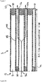
- a catalytic wall-flow monolith for use in an emission treatment system, the monolith comprising a porous substrate and having a first face and a second face defining a longitudinal direction therebetween and first and second pluralities of channels extending in the longitudinal direction, wherein the first plurality of channels provides a first plurality of inner surfaces and is open at the first face and closed at the second face, and wherein the second plurality of channels are open at the second face and closed at the first face, wherein a first catalytic material is distributed throughout the porous substrate, wherein a microporous membrane is provided in the first plurality of channels, coating the first plurality of inner surfaces, and wherein the microporous membrane has a thickness which increases along the longitudinal direction, such that the thickness is greatest in a region adjacent the closed second face.
- microporous membranes are coatings which have pores sized to be smaller than the soot particles being recovered. This means that the membrane permits the through-flow of gases for treatment, but prevents the build-up of soot within the larger pores of the porous substrate in areas protected by the membrane. The provision of a microporous membrane therefore prevents the build-up of back pressure in those regions, in use.
- the inventors have found that if they control the amount of soot going to the rear of the filter, then when conducting soot regeneration, more soot burns in the front than in the back, based on where it has accumulated in use. Typically, in conventional filters, more soot accumulates at the back, leading to a significant temperature gradient and reducing the longevity of the device. Preventing soot deposition at the back of the filter can reduce the temperatures reached in the rear of the filter during regeneration, improving the durability of the filter with respect to filter damage.
- the present invention relates to a catalytic wall-flow monolith for use in an emission treatment system.
- Wall-flow monoliths are well-known in the art for use in diesel particulate filters. They work by forcing a flow of exhaust gases (including particulate matter) to pass through walls formed of a porous material.
- the monolith is a filter including an SCR catalyst.
- the monolith has a first face and a second face defining a longitudinal direction therebetween.
- the first face will be the inlet face for exhaust gases and the second face will be the outlet face for the treated exhaust gases.
- first and second pluralities of channels extending in the longitudinal direction.
- the first plurality of channels is open at the first face and closed at the second face.
- the second plurality of channels is open at the second face and closed at the first face.
- the channels are preferably parallel to each other to provide a constant wall thickness between the channels.
- gases entering one of the plurality of channels cannot leave the monolith without diffusing through the channel walls into the other plurality of channels.
- the channels are closed with the introduction of a sealant material into the open end of a channel.
- the number of channels in the first plurality is equal to the number of channels in the second plurality, and each plurality is evenly distributed throughout the monolith.
- the first plurality of channels provides a first plurality of inner surfaces.
- the second plurality of channels provides a second plurality of inner surfaces.
- the monolith is formed out of a porous substrate.
- the substrate also acts as a support for holding catalytic material.
- Suitable materials for forming the porous substrate include ceramic-like materials such as cordierite, ⁇ -alumina, silicon carbide, silicon nitride, zirconia, mullite, spodumene, alumina-silica-magnesia or zirconium silicate, or porous, refractory metal.
- Wall-flow substrates may also be formed of ceramic fiber composite materials. Preferred wall-flow substrates are formed from cordierite and silicon carbide. Such materials are able to withstand the environment, particularly the high temperatures, encountered in treating the exhaust streams and can be made sufficiently porous. Such materials and their use in the manufacture of porous monolith substrates is well known in the art.
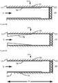
- catalytic material In order to provide a catalytic wall-flow monolith, catalytic material must be applied to the porous substrate, typically in the form of a washcoat.
- the application may be characterised as “on wall” application or “in wall” application.
- the former is characterised by the formation of a coating layer on a surface of a channel, such as the microporous membrane discussed herein.
- the latter is characterised by the infiltration of catalytic material into the pores within the porous material.
- the techniques for "in wall” or “on wall” application can depend on the viscosity of the material applied, the application technique (spraying or dipping, for example) and the presence of different solvents. Such application techniques are known in the art.
- the viscosity of the washcoat is influenced, for example, by its solids content. It is also influenced by the particle size distribution of the washcoat - a relatively flat distribution will give a different viscosity to a finely milled washcoat with a sharp peak in its particle size distribution - and rheology modifiers such as guar gums and other gums. Suitable coating methods are described in WO2011/080525 , WO1999/047260 and WO2014/195685 , which are incorporated herein by reference.
- Catalysts for use as the catalytic materials include zeolites, such as ZSM- 5, mordenite, gamma zeolite and beta zeolite or mixtures of any two or more thereof.
- the zeolite can be metallised or non-metallised e.g. with Fe, V, Cu, Ce, Fe or Pt or any two or more thereof. Where metallised, the metal can be applied using known techniques such as impregnation or ion-exchange.
- the monolith is a selective catalytic reductant filter (SCR). Suitable catalysts for NO x reduction are known in the art, and are described, for example, in WO2009/001131 , WO2010/043891 and WO2008/106519 .
- an SCR monolith is able to both reduce NO x in exhaust streams and remove particulate matter in a single unit.
- the catalytic material comprises a small-pore zeolite.
- Small pore zeolites with particular application for treating NO x in exhaust gases of lean-burn combustion engines include zeolites selected from the CHA, LEV, ERI, DDR, KFI, EAB, PAU, MER, AEI, GOO, YUG, GIS, VNI and AFT structural families. Suitable examples are described in WO2008/132452 , which is incorporated herein by reference. Small pore zeolites from the CHA and AEI families are especially preferred.
- the small pore zeolite is preferably metallized with Cu and/or Fe, optionally including Ce.
- the small pore zeolite may be metallized with precious metals (including gold, silver and platinum-group-metals), preferably with platinum-group-metals, more preferably palladium or platinum, and most preferably palladium.
- the catalytic material is distributed throughout the porous substrate. That is, preferably the catalytic material is preferably uniformly and homogeneously distributed throughout the porous substrate.
- the monolith of the present invention has been treated so as to have only a section of the porous substrate filled with catalytic material.
- one end of the monolith forms the first section and the remainder at the other end forms the second section.
- the second section contains the catalytic material.
- the catalytic material is distributed throughout the second section of the porous substrate. That is, preferably the catalytic material is preferably uniformly and homogeneously distributed throughout the section.
- the first section does not contain any catalytic material (or indeed, any added material) within the porous substrate.
- a ratio of a length of the first section in the longitudinal direction to the length of the second section in the longitudinal direction is from 5:95 to 15:85, preferably about 10:90.
- the border between the first and second portions will be in a plane parallel to the first and second faces. This facilitates the wash-coating process.
- a border which varies across the cross-section of the monolith such as a cone-shaped border. This may advantageously be used to increase the volume of the second portion within the monolith, since a centre portion of the monolith does experience elevated temperatures.
- a microporous membrane is provided in the first plurality of channels, coating the first plurality of inner surfaces.
- the microporous coating is not provided on the second plurality of surfaces.
- the membrane is provided on 75 to 95% of the length of the first channels, preferably 80 to 90%. This length is the internal length of the cavity from the first face to the internal sealed end of the first plurality of channels. Since the coating extends from the first face, this means that the rear portion of the channels is not coated.
- the plurality of first inner surfaces are fully coated.
- the microporous membrane can be made of a variety of materials, including polymeric membranes and inorganic membranes.
- Inorganic materials which can be used include sintered metals and ceramic membranes.
- Ceramic membranes can include alumina, zirconia, titania, silica, zircon, cordierite, mullite, spinel, silicon carbide, silicon nitride, and mixtures thereof, bonded by thermal sintering or with a reactive inorganic binder.
- the pore size of the microporous membrane is such that the soot particles cannot pass through the membrane.
- the mean pore diameter of the membrane coating is from about 0.1 micron to 5 micron, more preferably 0.2 to 1 microns.
- the catalyst membrane may be in the form of a permeable, semi-permeable, or non-permeable membrane.
- a membrane is a catalyst coating wherein the thickness of the coating is about 0.1 to 15% of the thickness of the wall upon which the membrane is disposed.
- a membrane can also contain about 5-40% of the catalyst material based on the total weight of the catalyst material loaded on the filter as a whole.
- the membrane may be on the inlet or outlet side of the porous wall.
- the membrane may cover 100% of the filter length or may cover only 10-90% of the filter length, measured from either in the inlet face or the outlet face.
- the membrane may cover 10-25%, 25-50%, 50-75%, 35-75%, or 75-70% of the filter length.
- the microporous membrane has a thickness which decreases along the longitudinal direction, such that the thickness is greatest in a region adjacent the first face.
- the membrane may also comprise a catalyst concentration gradient with the high concentration of catalyst being toward the inlet end of the filter.
- a protective polymeric coating such as polyvinyl acetate
- the protective polymeric coating may be burnt off.
- the microporous membrane can be applied by a spraying or dipping approach, but the material used to form it can be substantially prevented from infiltrating the porous substrate by one of several techniques, such as using a thick and viscous coating solution as described above.
- the microporous coating may extend into a surface region and infiltrate pores close to the surface of the substrate. This may be necessary for the membrane to adhere to the substrate.
- the membrane on the surface of the first plurality of channels penetrates to less than 25%, preferably 10%, preferably less than 5% of the channel wall thickness.
- the microporous membrane comprises a second catalytic material different from the first catalytic material, preferably a soot combustion promoter catalyst.
- a soot combustion promoter catalyst Most preferred examples include Cu on Ceria, Ce/Zr, or Ceria.
- the microporous membrane contains a material for adsorbing or otherwise capturing a catalyst poison such as ash, Na, Pt, sulphur oxides, Fe, and the like.
- a catalyst poison such as ash, Na, Pt, sulphur oxides, Fe, and the like.
- a catalyst poison such as ash, Na, Pt, sulphur oxides, Fe, and the like.
- ceria e.g., zeolite in the H-form.
- the microporous membrane contains a catalyst for urea hydrolysis.
- Suitable coating materials are disclosed in US8071037 .
- the mean cross-sectional width of the first and second pluralities of channels, in combination with the porous walls, results in a cell per square inch (CPSI) of 100 to 600.
- the channels may be of a constant width and each plurality of channels may have a uniform channel width.
- the plurality of channels that serves as the inlet in use has a greater mean cross-sectional width than the plurality of channels that serves as the outlet.
- the difference is at least 10%. This affords an increased ash storage capacity in the filter, meaning that a lower regeneration frequency can be used.
- Asymmetric filters are described in WO 2005/030365 , which is incorporated herein by reference.
- the mean minimum thickness of the substrate between adjacent channels is from 8 to 20 mil (where a "mil” is 1/1000 inch) (0.02 to 0.05 cm). Since the channels are preferably parallel and preferably have a constant width, the minimum wall thickness between adjacent channels is preferably constant. As will be appreciated, it is necessary to measure the mean minimum distance to ensure a reproducible measurement. For example, if the channels have a circular cross-section and are closely packed, then there is one clear point when the wall is thinnest between two adjacent channels.
- the wall thickness is preferably associated with the wall porosity and/or mean pore size. For example, the wall thickness to mean pore size is between 10 and 50.
- the monolith has from 100 to 500 channels per square inch, preferably from 200 to 400.
- the density of open first channels and closed second channels is from 200 to 400 channels per square inch.
- the channels can have cross sections that are rectangular, square, circular, oval, triangular, hexagonal, or are of other polygonal shapes.
- a catalytic wall-flow monolith for use in an emission treatment system, the monolith comprising a porous substrate and having a first face and a second face defining a longitudinal direction therebetween and first and second pluralities of channels extending in the longitudinal direction, wherein the first plurality of channels provides a first plurality of inner surfaces and is open at the first face and closed at the second face, and wherein the second plurality of channels are open at the second face and closed at the first face, wherein a first catalytic material is distributed throughout the porous substrate, wherein a microporous membrane is provided in the first plurality of channels, coating the first plurality of inner surfaces, and wherein the microporous membrane has a thickness which increases along the longitudinal direction, such that the thickness is greatest in a region adjacent the closed second face.
- the microporous membrane has a thickness in the region adjacent the closed second surface such that the backpressure, in use, is at least 20% greater than the backpressure in a region adjacent the first face.
- an emission treatment system for treating a flow of a combustion exhaust gas, the system comprising the catalytic wall-flow monolith as described herein, wherein the first face is upstream of the second face.
- Selective infiltration of the substrate is possible by immersing the substrate vertically in a portion of the catalyst slurry such that the desired boundary between the first and second substrate portions is at the surface of the slurry.
- the sample is left in the slurry for about 30 seconds.
- the substrate is removed from the slurry, and excess slurry is removed from the wall-flow substrate first by allowing it to drain from the channels, then by blowing with compressed air (against the direction of slurry penetration), and then by pulling a vacuum from the direction of slurry penetration.
- the catalyst slurry permeates the walls of the first portion of the substrate, yet the pores are not occluded to the extent that undue back pressure will build up in the finished substrate.
- the coated substrates are dried typically at about 100 °C and calcined at a higher temperature (e. g. 300 to 450 °C). After calcining, the catalyst loading canbe determined through calculation of the coated and uncoated weights of the substrate. As will be apparent to those of skill in the art, the catalyst loading can be modified by altering the solids content of the coating slurry. Alternatively, repeated immersions of the substrate in the coating slurry can be conducted, followed by removal of the excess slurry as described above.
- the coating of the microporous membrane is formed as described above and in WO2011/080525 , WO1999/047260 and WO2014/195685 .
- the surface in the first portion may be pre-coated with a protective polymeric film, such as polyvinyl acetate. This prevents the catalytic material from adhering to the surface in the first portion.
- the protective polymeric coating may then be burnt off.
- a catalytic wall-flow monolith for use in an emission treatment system, the monolith comprising a porous substrate and having a first face and a second face defining a longitudinal direction therebetween and first and second pluralities of channels extending in the longitudinal direction, wherein the first plurality of channels provides a first plurality of inner surfaces and is open at the first face and closed at the second face, and wherein the second plurality of channels is open at the second face and closed at the first face, wherein a first catalytic material is distributed throughout the porous substrate, wherein a microporous membrane is provided in the first plurality of channels on a first portion extending in the longitudinal direction of the first plurality of inner surfaces, and wherein the first portion extends from the first face for 80 to 90% of a length of the first plurality of channels.
- the on-wall coating in the form of the microporous membrane, this prevents soot depositing into the wall for a majority of the channels and hence the soot loaded backpressure is lower where there is on-wall coating.
- the soot in these regions forms a surface layer but does not have the same inhibiting effect on the gas flow.
- the region in the rear zone does not have a microporous coating so that soot can be deposited in the pores of the walls and this results in a backpressure which is higher in the rear. After initial loading in use, this elevated back pressure reduces the relative amount of soot which will load in the rear portion of the channels. This consequentially reduces the exotherms in that region during active soot regeneration, improving the durability of the filter against cracking/peak temps.
- a catalytic wall-flow monolith for use in an emission treatment system, the monolith comprising a porous substrate and having a first face and a second face defining a longitudinal direction therebetween and first and second pluralities of channels extending in the longitudinal direction, wherein the first plurality of channels provides a first plurality of inner surfaces and is open at the first face and closed at the second face, and wherein the second plurality of channels is open at the second face and closed at the first face, wherein a first catalytic material is distributed throughout the porous substrate, wherein a microporous membrane is provided in the first plurality of channels on a first portion extending in the longitudinal direction of the first plurality of inner surfaces, and wherein the first portion extends from the first face for 75 to 95% of a length of the first plurality of channels, and wherein the microporous membrane has a thickness which decreases along the longitudinal direction, such that the thickness is greatest in a region adjacent the first face.
- microporous membrane helps to prevent soot going into the wall in the first portion of the channels.
- a gradually increasing amount of soot will enter into the porous substrate. This provides an increasing backpressure in the channel 5 towards the back of the channel. This helps to further reduce the temperature gradients which occur on thermal regeneration.
- a catalytic wall-flow monolith for use in an emission treatment system, the monolith comprising a porous substrate and having a first face and a second face defining a longitudinal direction therebetween and first and second pluralities of channels extending in the longitudinal direction, wherein the first plurality of channels provides a first plurality of inner surfaces and is open at the first face and closed at the second face, and wherein the second plurality of channels is open at the second face and closed at the first face, wherein a first catalytic material is distributed within the porous substrate, wherein a microporous membrane is provided in the first plurality of channels on a first portion extending in the longitudinal direction of the first plurality of inner surfaces, and wherein the first portion extends from the first face for 75 to 95% of a length of the first plurality of channels, wherein the porous substrate has a first section extending in the longitudinal direction from the first face and a second section extending in the longitudinal direction from the second face and extending to the first section, and where
- the back pressure is very low in this section. Accordingly, soot build up on the surface of the microporous membrane in this section is increased and this, consequentially, reduces the soot loading in the rear portion and results in better durability.
- a catalytic wall-flow monolith for use in an emission treatment system, the monolith comprising a porous substrate and having a first face and a second face defining a longitudinal direction therebetween and first and second pluralities of channels extending in the longitudinal direction, wherein the first plurality of channels provides a first plurality of inner surfaces and is open at the first face and closed at the second face, and wherein the second plurality of channels are open at the second face and closed at the first face, wherein a first catalytic material is distributed throughout the porous substrate, wherein a microporous membrane is provided in the first plurality of channels, coating the first plurality of inner surfaces, and wherein the microporous membrane has a thickness which increases along the longitudinal direction, such that the thickness is greatest in a region adjacent the closed second face.
- the coating can have a direct effect on increasing the backpressure in the rear portion of the first channels. That is, the thickness of the coating can provide sufficient back-pressure to deter the deposition of soot in the rear portion.
- the coating should be sufficient such that the soot loaded back pressure is 20% higher in the rear than the front by virtue of the increased coating thickness in the rear section. This reduces soot deposition towards the rear of the monolith and helps to prevent undue heat build-up in this portion during regeneration.
- a method for treating a flow of a combustion exhaust gas comprising NO x and particulate matter comprising passing the exhaust stream through the monolith described herein, wherein the second face is downstream of the first face.
- the exhaust systems for the present invention are for internal combustion engines and in particular to lean-burn internal combustion engines, especially diesel engines.
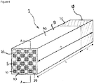
- a wall flow monolith 1 according to the present invention is shown in FIG. 1 and FIG. 2 . It includes a large number of channels arranged in parallel with each other in the longitudinal direction (shown by a double-sided arrow "a" in FIG. 1A ) of the monolith 1.
- the large number of channels includes a first subset of channels 5 and a second subset of channels 10.
- the channels are depicted such that the second subset of channels 10 is narrower than the first subset of channels 5. This has been found to provide an increased ash storage capacity in the filter. However, the channels may alternatively be the same size.
- the first subset of channels 5 is open at an end portion on a first end face 15 of the wall flow monolith 1 and is sealed with a sealing material 20 at an end portion on a second end face 25.
- the second subset of channels 10 is open at an end portion on the second end face 25 of the wall flow monolith 1 and is sealed with a sealing material 20 at an end portion on the first end face 15.
- the porous material 40 of the wall-flow monolith 1 is provided with a catalytic material, such as a zeolite, within pores of the channels walls 35.
- a catalytic material such as a zeolite
- This may be provided with a washcoat application method, as is known in the art and is discussed elsewhere in the specification.
- the catalytic material is distributed throughout the porous material 40, except in certain embodiments as described below.
- the channel walls 35 of the first subset of channels 5 are provided with a microporous membrane 36 on at least a portion thereof.
- the channel walls of the second subset of channels 10 are not coated.
- Figure 2 shows how the wall-flow filter works but does not show the microporous membrane 36.
- Embodiments of the microporous membrane 36 are shown in Figures 3A-3C and Figure 4 .
- exhaust gases G in FIG. 2 , "G" indicates exhaust gases and the arrow indicates a flowing direction of exhaust gases
- the channel wall 35 interposed between the channel 5a and the channels 10a and 10b, and then flow out from the monolith 1. Accordingly, particulate matter in exhaust gases is captured by the channel wall 35.
- the zeolite supported in the channel wall 35 of the monolith 1 functions as a catalyst for catalytic reduction which acts on NO x in combination with a reducing agent such as ammonia to reduce NO x to N 2 .
- the microporous coating is provided on the channel walls 35 of the first subset of channels 5 such that about 90% of the channel length (measured from the first end face 15 to the sealed end of the channel) and starting from the first end face 15 has the microporous coating.
- the thickness of the coating is substantially uniform.
- the inventors have found that by providing the on-wall coating along the channel 5, but for less than the full length of the channel 5, they can affect the build-up of soot within the channel 5.
- the soot tends to build up particularly towards the end of the channel.
- the presence of the additional soot leads to a steep temperature gradient within the monolith. This leads to cracking and a significant shortening of the effective life of the filter.
- the on-wall coating in the form of the microporous membrane 36 By providing the on-wall coating in the form of the microporous membrane 36, this stops soot going into the wall for a majority of the channels and hence the soot loaded backpressure is lower where there is on-wall coating.
- the soot in these regions forms a surface layer but does not have the same inhibiting effect on the gas flow.
- the region in the rear zone does not have a microporous coating so that soot can be deposited in the pores of the walls and this results in a backpressure which is higher in the rear. After initial loading, this elevated back pressure reduces the relative amount of soot which will load in the rear portion of the channels 5. This consequentially reduces the exotherms in that region during active soot regeneration, improving the durability of the filter against cracking/peak temps.
- the microporous coating is provided on the channel walls 35 of the first subset of channels 5 such that 90% of the channel length (measured from the first end face 15 to the sealed end of the channel) and starting from the first end face 15 has the microporous coating.
- the thickness of the coating is decreases along the channels 5, such that the coating is thickest close to the first end face 15.
- applying the microporous membrane 36 helps to prevent soot going into the wall in the first portion of the channels 5.
- a gradually increasing amount of soot will enter into the porous substrate. This provides an increasing backpressure in the channel 5 towards the back of the channel. This helps to further reduce the temperature gradients which occur on thermal regeneration.
- the microporous coating is provided on the channel walls 35 of the first subset of channels 5 such that 90% of the channel length (measured from the first end face 15 to the sealed end of the channel) and starting from the first end of the channel 5 has the microporous coating.
- the thickness of the coating is substantially uniform.
- the porous substrate 40 in this embodiment is divided into two sections. A first section 50 starting from the first face which does not include any catalytic material, and a second section 51 (the remainder) which has the catalytic material distributed throughout.
- the back pressure is very low. Accordingly, soot build up on the surface of the microporous membrane 36 is increased and this, consequentially, reduces the soot loading in the rear portion and results in better durability.
- FIG 4 is a perspective view that schematically shows a wall flow monolith filter 1 according to the present invention.
- the wall flow monolith shows the first section 50 and the second section 51.
- the microporous coating is provided on the channel walls 35 of the first subset of channels 5 such that 100% of the channel length (measured from the first end face 15 to the sealed end of the channel) has the microporous coating.
- the thickness of the coating on the channels 5 is such that the coating is thickest close to the closed second end face 25.
- the catalytic material is distributed throughout the porous material.
- the coating can have a direct effect on increasing the backpressure in the rear portion of the first channels.
- the coating should be sufficient such that the soot loaded back pressure is 20% higher in the rear than the front by virtue of the increased coating thickness in the rear section. This reduces soot deposition towards the rear of the monolith and helps to prevent undue heat build-up in this portion during regeneration.
- an ammonia reductant 105 is injected into the flow of exhaust gas 110 upstream of the wall flow monolith 1.
- the exhaust gas 110 is passed from the engine 115 through ducting 120 to the exhaust system 125.
- the ammonia reductant 105 is dispensed from a reservoir 130 as required (as determined by controller 135) through an injection nozzle 140 and mixes with the exhaust gas prior to reaching the monolith 1 which acts as an SCR device.
- the wall flow monolith is described herein as a single component. Nonetheless, when forming an emission treatment system, the monolith used may be formed by adhering together a plurality of channels or by adhering together a plurality of smaller monoliths as described herein. Such techniques are well known in the art, as well as suitable casings and configurations of the emission treatment system.
- the membrane may be on the inlet or outlet side of the porous wall.
- the membrane may cover 10-90% of the filter length, measure from either in the inlet face or the outlet face.
- the membrane may cover 10-25%, 25-50%, 50-75%, 35-75%, or 75-70% of the filter length.
- the catalytic and/or adsorbent material of the membrane may comprise an SCR catalyst as defined here, a NOx trap, a soot oxidation catalyst, a hydrolysis catalyst, an adsorbent for metals such as V, Pt, Pd, Rh, Ru, Na, Cu, Fe, Co, Nu, and Cr, or for other poisons such as ash and/or sulphur oxides.
- Examples of catalytic and/or adsorbent materials include metal loaded zeolites, such as Cu/CHA, Cu/AEI, Fe/CHA, Pd/CHA, and the like, H-form zeolites, supported platinum group metals, etc.
- the membrane is applied as a catalyst washcoat that contains the catalyst and optionally one or more other constituents such as binders (e.g., metal oxide particles), fibers (e.g., glass or ceramic non-woven fibers), masking agents, rheology modifiers, and pore formers.
- binders e.g., metal oxide particles
- fibers e.g., glass or ceramic non-woven fibers
- All or any combination of these features in a membrane can improve soot-loaded backpressure (particularly in combination with filter efficiency), reduce exotherms during filter regeneration, improve filter thermal and mechanical durability (e.g. avoid cracking, peeling, etc.), protect temperature sensitive catalyst from high temperature spike, improve catalyst performance overall and on per weight basis, lower N2O formation, allows better NH3 utilization, and capture poisons such as Pt, ash, sulfur oxides, Na, Fe, and mitigate the potential loss of metals via volatilization.
- a catalytic wall-flow monolith for use in an emission treatment system, the monolith comprising a porous substrate and having a first face and a second face defining a longitudinal direction therebetween and first and second pluralities of channels extending in the longitudinal direction, wherein the first plurality of channels provides a first plurality of inner surfaces and is open at the first face and closed at the second face, and wherein the second plurality of channels is open at the second face and closed at the first face, wherein a first catalytic material is distributed within the porous substrate, wherein a microporous membrane is provided in the first plurality of channels on a first portion, extending in the longitudinal direction, of the first plurality of inner surfaces, and wherein the first portion extends from the first face for 75 to 95% of a length of the first plurality of channels.
- microporous membrane has a thickness which decreases along the longitudinal direction, such that the thickness is greatest in a region adjacent the first face.
- the catalytic wall-flow monolith as hereinbefore defined wherein the porous substrate has a first section extending in the longitudinal direction from the first face and a second section extending in the longitudinal direction from the second face and extending to the first section, and wherein the first catalytic material is distributed throughout the second section.
- a catalytic wall-flow monolith for use in an emission treatment system, the monolith comprising a porous substrate and having a first face and a second face defining a longitudinal direction therebetween and first and second pluralities of channels extending in the longitudinal direction, wherein the first plurality of channels provides a first plurality of inner surfaces and is open at the first face and closed at the second face, and wherein the second plurality of channels are open at the second face and closed at the first face, wherein a first catalytic material is distributed throughout the porous substrate, wherein a microporous membrane is provided in the first plurality of channels, coating the first plurality of inner surfaces, and wherein the microporous membrane has a thickness which increases along the longitudinal direction, such that the thickness is greatest in a region adjacent the closed second face.
- microporous membrane comprises a second catalytic material different from the first catalytic material, preferably a soot combustion promoter catalyst.
- the catalytic wall-flow monolith as hereinbefore defined further comprising a coating on the microporous membrane for capturing ash, wherein the coating preferably comprises ceria.
- the catalytic wall-flow monolith as hereinbefore defined further comprising a coating on the microporous membrane for catalytic urea hydrolysis.
- a catalytic wall-flow monolith as hereinbefore defined wherein the catalytic material distributed throughout the porous substrate is selected from small-pore zeolites selected from the CHA, LEV, ERI, DDR, KFI, EAB, PAU, MER, AEI, GOO, YUG, GIS, VNI and AFT structural families.
- An emission treatment system for treating a flow of a combustion exhaust gas comprising the catalytic wall-flow monolith as hereinbefore defined, wherein the second face is downstream of the first face.
- a method for treating a flow of a combustion exhaust gas comprising NO x and particulate matter comprising passing the exhaust stream through the monolith as hereinbefore defined, wherein the second face is downstream of the first face.
- a catalytic wall-flow monolith for use in an emission treatment system, the monolith comprising a porous substrate and having a first face and a second face defining a longitudinal direction therebetween and first and second pluralities of channels extending in the longitudinal direction, wherein the first plurality of channels provides a first plurality of inner surfaces and is open at the first face and closed at the second face, and wherein the second plurality of channels is open at the second face and closed at the first face, wherein a first catalytic material is distributed within the porous substrate from the first face for 75 to 95% of a length of the first plurality of channels, wherein a microporous membrane is disposed on the porous substrate along the length of the first and/or second plurality of channels.
Abstract
the monolith comprising a porous substrate and having a first face and a second face defining a longitudinal direction therebetween and first and second pluralities of channels extending in the longitudinal direction,
wherein the first plurality of channels provides a first plurality of inner surfaces and is open at the first face and closed at the second face, and wherein the second plurality of channels is open at the second face and closed at the first face,
wherein a first catalytic material is distributed within the porous substrate,
wherein a microporous membrane is provided in the first plurality of channels on a first portion, extending in the longitudinal direction, of the first plurality of inner surfaces.
Description
- The present invention relates to a catalytic wall-flow monolith suitable for use in an emission treatment system, such as an automobile internal combustion exhaust system. The monolith provides an effective method of remediating engine exhaust streams.
- Emissions from internal combustion engines, including diesel engines, are limited by legislation put in place by governments worldwide. Manufacturers are seeking to meet these legislated requirements through a combination of engine design and exhaust gas after-treatment. The exhaust systems used to carry out exhaust gas after-treatment commonly comprise a series of catalysts and/or filters that are designed to carry out certain reactions that reduce the proportion of exhaust gas species limited by such legislation.
- A diesel engine exhaust stream is a heterogeneous mixture which contains not only gaseous emissions such as carbon monoxide ("CO"), unburned hydrocarbons ("HC") and nitrogen oxides ("NOx"), but also condensed phase materials (liquids and solids) which constitute the so-called particulates or particulate matter. Often, catalyst compositions and substrates on which the compositions are disposed are provided in diesel engine exhaust systems to convert certain or all of these exhaust components to innocuous components. For example, diesel exhaust systems can contain one or more of a diesel oxidation catalyst, a soot filter and a catalyst for the reduction of NOx.
- The total particulate matter emissions of diesel exhaust streams include a solid, dry, carbonaceous fraction, a so-called soot fraction. This dry carbonaceous matter contributes to the visible soot emissions commonly associated with diesel exhausts.
- One key after-treatment technology in use for high particulate matter reduction is the diesel particulate filter. There are many known filter structures that are effective in removing particulate matter from diesel exhaust streams, such as honeycomb wall-flow filters, wound or packed fiber filters, open cell foams, sintered metal filters, etc. However, ceramic wall flow filters, described below, receive the most attention. These filters are capable of removing over 90% of the particulate material from diesel exhaust streams. The filter is a physical structure for removing particles from exhaust streams, and the accumulating particles will increase the back pressure from the filter on the engine. Thus the accumulating particles have to be continuously or periodically burned out of the filter to maintain an acceptable back pressure. Unfortunately, the carbon soot particles require temperatures in excess of 500 °C to burn under oxygen rich (lean) exhaust conditions. This temperature is higher than what is typically present in diesel exhaust streams.
- Accordingly, it is necessary to actively burn the accumulated soot in order to promote filter regeneration. One form of active filter regeneration is to intermittently introduce additional hydrocarbon fuel into the exhaust gas and to combust this in order to increase the filter temperature. Combustion of the additional hydrocarbon fuel can be effected on the filter itself by coating the filter with a suitable combustion-promoting catalyst. A suitably catalysed filter is often referred to as a catalysed soot filter or CSF.
- During active regeneration the CSF may need to reach temperatures of approximately 600° C. to permit particulate matter to be removed (combusted) at a sufficient rate. However, if during an active regeneration event, a period of low exhaust gas flow occurs, e.g. when the engine/vehicle is caused to idle, the reduced gas flow prevents heat from being removed from the CSF. This can result in parts of the filter reaching temperatures in excess of 1000° C. Such high temperatures can cause two major problems. Firstly, the catalyst can sinter, reducing its surface area and as a consequence catalyst activity is lost. Secondly, high thermal gradients can occur in the substrate leading to mechanical stress caused by differences in thermal expansion. Under extreme conditions the thermal gradients and stresses can cause substrates to crack thereby resulting in a failure of the integrity of the CSF.
- Therefore, the challenge is in controlling the active regeneration of the CSF so that it can reach temperatures sufficiently high to remove particulate matter but not so high as to cause damage to the catalyst and/or the filter substrate.
- As noted above diesel exhaust streams also contain NOx. A proven NOx abatement technology applied to stationary sources with lean exhaust conditions is Selective Catalytic Reduction (SCR). In this process, NOx is reduced with ammonia (NH3) to nitrogen (N2) over a catalyst typically composed of base metals. The technology is capable of NOx reduction greater than 90%, and thus it represents one of the best approaches for achieving aggressive NOx reduction goals. SCR provides efficient conversions of NOx as long as the exhaust temperature is within the active temperature range of the catalyst.
- Separate substrates, each containing catalysts to address discrete components of the exhaust can be provided in an exhaust system. However, use of fewer substrates is desirable to reduce the overall size of the system, to ease the assembly of the system, and to reduce the overall cost of the system. One approach to achieve this goal is to coat the soot filter with a catalyst composition effective for the conversion of NOx to innocuous components. With this approach, the catalysed soot filter assumes two catalyst functions: removal of the particulate component of the exhaust stream and conversion of the NOx component of the exhaust stream to nitrogen.
- Coated soot filters that can achieve NOx reduction goals require a sufficient loading of SCR catalyst composition on the soot filter. The gradual loss of the catalytic effectiveness of the compositions that occurs over time through exposure to certain deleterious components of the exhaust stream augments the need for higher catalyst loadings of the SCR catalyst composition. However, preparation of coated soot filters with higher catalyst loadings can lead to unacceptably high back pressure within the exhaust system. Coating techniques that allow higher catalyst loadings on the wall flow filter, yet still allow the filter to maintain flow characteristics that achieve acceptable back pressures are therefore desirable.
An additional aspect for consideration in coating the wall-flow filter is the selection of the appropriate SCR catalyst composition. First, the catalyst composition must be durable so that it maintains its SCR catalytic activity even after prolonged exposure to higher temperatures that are characteristic of filter regeneration. For example, combustion of the soot fraction of the particulate matter often leads to temperatures above 700 °C. Such temperatures render many commonly used SCR catalyst compositions such as mixed oxides of vanadium and titanium less catalytically effective. Second, the SCR catalyst compositions preferably have a wide enough operating temperature range so that they can accommodate the variable temperature ranges over which the vehicle operates. Temperatures below 300 °C are typically encountered, for example, at conditions of low load, or at startup. The SCR catalyst compositions are preferably capable of catalyzing the reduction of the NOx component of the exhaust to achieve NOx reduction goals, even at lower exhaust temperatures. -
US8617476 discloses a honeycomb filter characterised by the amount of zeolite supported on the channel walls and the thermal conductivity of the walls. -
US8398925 discloses a particulate filer substrate for an internal combustion engine. The filter substrate is coated with a washcoat having regions of different densities. -
WO2005016497 discloses an exhaust treatment system. -
US2012/0247092 discloses a multi-component filter for emission control. -
US2014/0140899 discloses a catalysed particulate filter. -
WO2011140248 discloses catalysed soot filters and emission treatment systems. -
US5221484 discloses a catalytic filtration system and method. - Accordingly, it is desirable to provide an improved wall-flow monolith and/or tackle at least some of the problems associated with the prior art or, at least, to provide a commercially useful alternative thereto.
- According to a first aspect there is provided a catalytic wall-flow monolith for use in an emission treatment system,
the monolith comprising a porous substrate and having a first face and a second face defining a longitudinal direction therebetween and first and second pluralities of channels extending in the longitudinal direction,
wherein the first plurality of channels provides a first plurality of inner surfaces and is open at the first face and closed at the second face, and wherein the second plurality of channels are open at the second face and closed at the first face,
wherein a first catalytic material is distributed throughout the porous substrate,
wherein a microporous membrane is provided in the first plurality of channels, coating the first plurality of inner surfaces, and
wherein the microporous membrane has a thickness which increases along the longitudinal direction, such that the thickness is greatest in a region adjacent the closed second face. - The present invention will now be further described. In the following passages different aspects of the invention are defined in more detail. Each aspect so defined may be combined with any other aspect or aspects unless clearly indicated to the contrary. In particular, any feature indicated as being preferred or advantageous may be combined with any other feature or features indicated as being preferred or advantageous.
- The present inventors have found that by providing the microporous membranes as discussed herein, it is possible to direct the soot deposition locations. Microporous membranes are coatings which have pores sized to be smaller than the soot particles being recovered. This means that the membrane permits the through-flow of gases for treatment, but prevents the build-up of soot within the larger pores of the porous substrate in areas protected by the membrane. The provision of a microporous membrane therefore prevents the build-up of back pressure in those regions, in use.
- The inventors have found that if they control the amount of soot going to the rear of the filter, then when conducting soot regeneration, more soot burns in the front than in the back, based on where it has accumulated in use. Typically, in conventional filters, more soot accumulates at the back, leading to a significant temperature gradient and reducing the longevity of the device. Preventing soot deposition at the back of the filter can reduce the temperatures reached in the rear of the filter during regeneration, improving the durability of the filter with respect to filter damage.
- Accordingly, the present invention relates to a catalytic wall-flow monolith for use in an emission treatment system. Wall-flow monoliths are well-known in the art for use in diesel particulate filters. They work by forcing a flow of exhaust gases (including particulate matter) to pass through walls formed of a porous material. Preferably the monolith is a filter including an SCR catalyst.
- The monolith has a first face and a second face defining a longitudinal direction therebetween. In use, the first face will be the inlet face for exhaust gases and the second face will be the outlet face for the treated exhaust gases.
- As is conventional for a wall-flow monolith, it has first and second pluralities of channels extending in the longitudinal direction. The first plurality of channels is open at the first face and closed at the second face. The second plurality of channels is open at the second face and closed at the first face. The channels are preferably parallel to each other to provide a constant wall thickness between the channels. As a result, gases entering one of the plurality of channels cannot leave the monolith without diffusing through the channel walls into the other plurality of channels. The channels are closed with the introduction of a sealant material into the open end of a channel. Preferably the number of channels in the first plurality is equal to the number of channels in the second plurality, and each plurality is evenly distributed throughout the monolith.
- The first plurality of channels provides a first plurality of inner surfaces. The second plurality of channels provides a second plurality of inner surfaces.
- In order to facilitate the passage of gases to be treated through the channel walls, the monolith is formed out of a porous substrate. The substrate also acts as a support for holding catalytic material. Suitable materials for forming the porous substrate include ceramic-like materials such as cordierite, α-alumina, silicon carbide, silicon nitride, zirconia, mullite, spodumene, alumina-silica-magnesia or zirconium silicate, or porous, refractory metal. Wall-flow substrates may also be formed of ceramic fiber composite materials. Preferred wall-flow substrates are formed from cordierite and silicon carbide. Such materials are able to withstand the environment, particularly the high temperatures, encountered in treating the exhaust streams and can be made sufficiently porous. Such materials and their use in the manufacture of porous monolith substrates is well known in the art.
- In order to provide a catalytic wall-flow monolith, catalytic material must be applied to the porous substrate, typically in the form of a washcoat. The application may be characterised as "on wall" application or "in wall" application. The former is characterised by the formation of a coating layer on a surface of a channel, such as the microporous membrane discussed herein. The latter is characterised by the infiltration of catalytic material into the pores within the porous material. The techniques for "in wall" or "on wall" application can depend on the viscosity of the material applied, the application technique (spraying or dipping, for example) and the presence of different solvents. Such application techniques are known in the art. The viscosity of the washcoat is influenced, for example, by its solids content. It is also influenced by the particle size distribution of the washcoat - a relatively flat distribution will give a different viscosity to a finely milled washcoat with a sharp peak in its particle size distribution - and rheology modifiers such as guar gums and other gums. Suitable coating methods are described in
WO2011/080525 ,WO1999/047260 andWO2014/195685 , which are incorporated herein by reference. - Catalysts for use as the catalytic materials include zeolites, such as ZSM- 5, mordenite, gamma zeolite and beta zeolite or mixtures of any two or more thereof. The zeolite can be metallised or non-metallised e.g. with Fe, V, Cu, Ce, Fe or Pt or any two or more thereof. Where metallised, the metal can be applied using known techniques such as impregnation or ion-exchange. Preferably the monolith is a selective catalytic reductant filter (SCR). Suitable catalysts for NOx reduction are known in the art, and are described, for example, in
WO2009/001131 ,WO2010/043891 andWO2008/106519 . Advantageously, an SCR monolith is able to both reduce NOx in exhaust streams and remove particulate matter in a single unit. - Preferably the catalytic material comprises a small-pore zeolite. Small pore zeolites with particular application for treating NOx in exhaust gases of lean-burn combustion engines include zeolites selected from the CHA, LEV, ERI, DDR, KFI, EAB, PAU, MER, AEI, GOO, YUG, GIS, VNI and AFT structural families. Suitable examples are described in
WO2008/132452 , which is incorporated herein by reference. Small pore zeolites from the CHA and AEI families are especially preferred. The small pore zeolite is preferably metallized with Cu and/or Fe, optionally including Ce. Alternatively, the small pore zeolite may be metallized with precious metals (including gold, silver and platinum-group-metals), preferably with platinum-group-metals, more preferably palladium or platinum, and most preferably palladium. - Preferably the catalytic material is distributed throughout the porous substrate. That is, preferably the catalytic material is preferably uniformly and homogeneously distributed throughout the porous substrate.
- In some embodiments, however, the monolith of the present invention has been treated so as to have only a section of the porous substrate filled with catalytic material. In particular, there can be a first section extending in the longitudinal direction from the first face and a second section extending in the longitudinal direction from the second face and extending to the first portion. In other words, one end of the monolith (relative to the flow of exhaust gases) forms the first section and the remainder at the other end forms the second section. In these embodiments, the second section contains the catalytic material. Preferably the catalytic material is distributed throughout the second section of the porous substrate. That is, preferably the catalytic material is preferably uniformly and homogeneously distributed throughout the section. In this embodiment, preferably the first section does not contain any catalytic material (or indeed, any added material) within the porous substrate.
- Preferably a ratio of a length of the first section in the longitudinal direction to the length of the second section in the longitudinal direction is from 5:95 to 15:85, preferably about 10:90.
- Typically, the border between the first and second portions will be in a plane parallel to the first and second faces. This facilitates the wash-coating process. However, it is also possible to have a border which varies across the cross-section of the monolith, such as a cone-shaped border. This may advantageously be used to increase the volume of the second portion within the monolith, since a centre portion of the monolith does experience elevated temperatures.
- A microporous membrane is provided in the first plurality of channels, coating the first plurality of inner surfaces. Preferably the microporous coating is not provided on the second plurality of surfaces. In the first aspect described herein, the membrane is provided on 75 to 95% of the length of the first channels, preferably 80 to 90%. This length is the internal length of the cavity from the first face to the internal sealed end of the first plurality of channels. Since the coating extends from the first face, this means that the rear portion of the channels is not coated. According to the second aspect, the plurality of first inner surfaces are fully coated.
- The microporous membrane can be made of a variety of materials, including polymeric membranes and inorganic membranes. Inorganic materials which can be used include sintered metals and ceramic membranes. Ceramic membranes can include alumina, zirconia, titania, silica, zircon, cordierite, mullite, spinel, silicon carbide, silicon nitride, and mixtures thereof, bonded by thermal sintering or with a reactive inorganic binder.
- The pore size of the microporous membrane is such that the soot particles cannot pass through the membrane. Preferably the mean pore diameter of the membrane coating is from about 0.1 micron to 5 micron, more preferably 0.2 to 1 microns.
- The catalyst membrane may be in the form of a permeable, semi-permeable, or non-permeable membrane. As used herein, a membrane is a catalyst coating wherein the thickness of the coating is about 0.1 to 15% of the thickness of the wall upon which the membrane is disposed. A membrane can also contain about 5-40% of the catalyst material based on the total weight of the catalyst material loaded on the filter as a whole.
- The membrane may be on the inlet or outlet side of the porous wall. The membrane may cover 100% of the filter length or may cover only 10-90% of the filter length, measured from either in the inlet face or the outlet face. For example, the membrane may cover 10-25%, 25-50%, 50-75%, 35-75%, or 75-70% of the filter length.
- In one embodiment, preferably the microporous membrane has a thickness which decreases along the longitudinal direction, such that the thickness is greatest in a region adjacent the first face. The membrane may also comprise a catalyst concentration gradient with the high concentration of catalyst being toward the inlet end of the filter.
- It is possible using conventional techniques to provide such "on wall" application as the microporous membrane to only a specific portion of the substrate. For example, a protective polymeric coating (such as polyvinyl acetate) can be applied to the remaining portion so that the membrane does not form there. Once the residual washcoat has been removed, for example under vacuum, the protective polymeric coating may be burnt off.
- The microporous membrane can be applied by a spraying or dipping approach, but the material used to form it can be substantially prevented from infiltrating the porous substrate by one of several techniques, such as using a thick and viscous coating solution as described above.
- For the avoidance of doubt, it is acknowledged that the microporous coating may extend into a surface region and infiltrate pores close to the surface of the substrate. This may be necessary for the membrane to adhere to the substrate. Preferably the membrane on the surface of the first plurality of channels penetrates to less than 25%, preferably 10%, preferably less than 5% of the channel wall thickness.
- Preferably the microporous membrane comprises a second catalytic material different from the first catalytic material, preferably a soot combustion promoter catalyst. Most preferred examples include Cu on Ceria, Ce/Zr, or Ceria.
- In certain aspects, the microporous membrane contains a material for adsorbing or otherwise capturing a catalyst poison such as ash, Na, Pt, sulphur oxides, Fe, and the like. One such example is ceria. Another example is bare zeolite (e.g., zeolite in the H-form).
- In certain aspects, the microporous membrane contains a catalyst for urea hydrolysis. Suitable coating materials are disclosed in
US8071037 . - Preferably the mean cross-sectional width of the first and second pluralities of channels, in combination with the porous walls, results in a cell per square inch (CPSI) of 100 to 600. The channels may be of a constant width and each plurality of channels may have a uniform channel width. Preferably, however, the plurality of channels that serves as the inlet in use has a greater mean cross-sectional width than the plurality of channels that serves as the outlet. Preferably, the difference is at least 10%. This affords an increased ash storage capacity in the filter, meaning that a lower regeneration frequency can be used. Asymmetric filters are described in
WO 2005/030365 , which is incorporated herein by reference. - Preferably the mean minimum thickness of the substrate between adjacent channels (i.e., wall thickness) is from 8 to 20 mil (where a "mil" is 1/1000 inch) (0.02 to 0.05 cm). Since the channels are preferably parallel and preferably have a constant width, the minimum wall thickness between adjacent channels is preferably constant. As will be appreciated, it is necessary to measure the mean minimum distance to ensure a reproducible measurement. For example, if the channels have a circular cross-section and are closely packed, then there is one clear point when the wall is thinnest between two adjacent channels. The wall thickness is preferably associated with the wall porosity and/or mean pore size. For example, the wall thickness to mean pore size is between 10 and 50.
- Preferably within a plane orthogonal to the longitudinal direction, the monolith has from 100 to 500 channels per square inch, preferably from 200 to 400. For example, on the first face, the density of open first channels and closed second channels is from 200 to 400 channels per square inch. The channels can have cross sections that are rectangular, square, circular, oval, triangular, hexagonal, or are of other polygonal shapes.
- According to a further aspect there is provided a catalytic wall-flow monolith for use in an emission treatment system,
the monolith comprising a porous substrate and having a first face and a second face defining a longitudinal direction therebetween and first and second pluralities of channels extending in the longitudinal direction,
wherein the first plurality of channels provides a first plurality of inner surfaces and is open at the first face and closed at the second face, and wherein the second plurality of channels are open at the second face and closed at the first face,
wherein a first catalytic material is distributed throughout the porous substrate,
wherein a microporous membrane is provided in the first plurality of channels, coating the first plurality of inner surfaces, and
wherein the microporous membrane has a thickness which increases along the longitudinal direction, such that the thickness is greatest in a region adjacent the closed second face. - Preferably the microporous membrane has a thickness in the region adjacent the closed second surface such that the backpressure, in use, is at least 20% greater than the backpressure in a region adjacent the first face.
- According to a further aspect there is provided an emission treatment system for treating a flow of a combustion exhaust gas, the system comprising the catalytic wall-flow monolith as described herein, wherein the first face is upstream of the second face.
- According to a further aspect there is provided a method for the manufacture of a catalytic wall-flow monolith as described herein, the method comprising:
- providing a porous substrate having a first face and an second face defining a longitudinal direction therebetween and first and second pluralities of channels extending in the longitudinal direction, wherein the first plurality of channels is open at the first face and closed at the second face, and wherein the second plurality of channels is open at the second face and closed at the first face, wherein the first plurality of channels provide a first plurality of inner surfaces and wherein the second plurality of channels provide a second plurality of inner surfaces;
- infiltrating the porous substrate with a washcoat containing a first catalytic material to provide the first catalytic material distributed within the porous substrate; and
- forming a microporous membrane on the first plurality of inner surfaces.
- Selective infiltration of the substrate is possible by immersing the substrate vertically in a portion of the catalyst slurry such that the desired boundary between the first and second substrate portions is at the surface of the slurry. The sample is left in the slurry for about 30 seconds. The substrate is removed from the slurry, and excess slurry is removed from the wall-flow substrate first by allowing it to drain from the channels, then by blowing with compressed air (against the direction of slurry penetration), and then by pulling a vacuum from the direction of slurry penetration. By using this technique, the catalyst slurry permeates the walls of the first portion of the substrate, yet the pores are not occluded to the extent that undue back pressure will build up in the finished substrate.
- The coated substrates are dried typically at about 100 °C and calcined at a higher temperature (e. g. 300 to 450 °C). After calcining, the catalyst loading canbe determined through calculation of the coated and uncoated weights of the substrate. As will be apparent to those of skill in the art, the catalyst loading can be modified by altering the solids content of the coating slurry. Alternatively, repeated immersions of the substrate in the coating slurry can be conducted, followed by removal of the excess slurry as described above.
- The coating of the microporous membrane is formed as described above and in
WO2011/080525 ,WO1999/047260 andWO2014/195685 . To prevent the coating from forming along the entire length of the channel surfaces, the surface in the first portion may be pre-coated with a protective polymeric film, such as polyvinyl acetate. This prevents the catalytic material from adhering to the surface in the first portion. The protective polymeric coating may then be burnt off. - The present disclosure encompasses, in particular, four preferred embodiments described in detail below.
- According to the first preferred embodiment, there is provided a catalytic wall-flow monolith for use in an emission treatment system,
the monolith comprising a porous substrate and having a first face and a second face defining a longitudinal direction therebetween and first and second pluralities of channels extending in the longitudinal direction,
wherein the first plurality of channels provides a first plurality of inner surfaces and is open at the first face and closed at the second face, and wherein the second plurality of channels is open at the second face and closed at the first face,
wherein a first catalytic material is distributed throughout the porous substrate,
wherein a microporous membrane is provided in the first plurality of channels on a first portion extending in the longitudinal direction of the first plurality of inner surfaces, and
wherein the first portion extends from the first face for 80 to 90% of a length of the first plurality of channels. - By providing the on-wall coating in the form of the microporous membrane, this prevents soot depositing into the wall for a majority of the channels and hence the soot loaded backpressure is lower where there is on-wall coating. The soot in these regions forms a surface layer but does not have the same inhibiting effect on the gas flow. The region in the rear zone does not have a microporous coating so that soot can be deposited in the pores of the walls and this results in a backpressure which is higher in the rear. After initial loading in use, this elevated back pressure reduces the relative amount of soot which will load in the rear portion of the channels. This consequentially reduces the exotherms in that region during active soot regeneration, improving the durability of the filter against cracking/peak temps.
- According to the second preferred embodiment, there is provided a catalytic wall-flow monolith for use in an emission treatment system,
the monolith comprising a porous substrate and having a first face and a second face defining a longitudinal direction therebetween and first and second pluralities of channels extending in the longitudinal direction,
wherein the first plurality of channels provides a first plurality of inner surfaces and is open at the first face and closed at the second face, and wherein the second plurality of channels is open at the second face and closed at the first face, wherein a first catalytic material is distributed throughout the porous substrate,
wherein a microporous membrane is provided in the first plurality of channels on a first portion extending in the longitudinal direction of the first plurality of inner surfaces, and
wherein the first portion extends from the first face for 75 to 95% of a length of the first plurality of channels,
and wherein the microporous membrane has a thickness which decreases along the longitudinal direction, such that the thickness is greatest in a region adjacent the first face. - This embodiment works in a similar way to the first embodiment. The microporous membrane helps to prevent soot going into the wall in the first portion of the channels. However, by providing a decreasing thickness of the microporous membrane, a gradually increasing amount of soot will enter into the porous substrate. This provides an increasing backpressure in the
channel 5 towards the back of the channel. This helps to further reduce the temperature gradients which occur on thermal regeneration. - According to the third preferred embodiment, there is provided a catalytic wall-flow monolith for use in an emission treatment system,
the monolith comprising a porous substrate and having a first face and a second face defining a longitudinal direction therebetween and first and second pluralities of channels extending in the longitudinal direction,
wherein the first plurality of channels provides a first plurality of inner surfaces and is open at the first face and closed at the second face, and wherein the second plurality of channels is open at the second face and closed at the first face, wherein a first catalytic material is distributed within the porous substrate,
wherein a microporous membrane is provided in the first plurality of channels on a first portion extending in the longitudinal direction of the first plurality of inner surfaces, and
wherein the first portion extends from the first face for 75 to 95% of a length of the first plurality of channels,
wherein the porous substrate has a first section extending in the longitudinal direction from the first face and a second section extending in the longitudinal direction from the second face and extending to the first section, and wherein the first catalytic material is distributed throughout the second section and, wherein the ratio of a length of the first section in the longitudinal direction to the length of the second section in the longitudinal direction is from 5:95 to 15:85. - As a result, since the first section has a high porosity the back pressure is very low in this section. Accordingly, soot build up on the surface of the microporous membrane in this section is increased and this, consequentially, reduces the soot loading in the rear portion and results in better durability.
- According to the fourth preferred embodiment, there is provided a catalytic wall-flow monolith for use in an emission treatment system,
the monolith comprising a porous substrate and having a first face and a second face defining a longitudinal direction therebetween and first and second pluralities of channels extending in the longitudinal direction,
wherein the first plurality of channels provides a first plurality of inner surfaces and is open at the first face and closed at the second face, and wherein the second plurality of channels are open at the second face and closed at the first face,
wherein a first catalytic material is distributed throughout the porous substrate,
wherein a microporous membrane is provided in the first plurality of channels, coating the first plurality of inner surfaces, and
wherein the microporous membrane has a thickness which increases along the longitudinal direction, such that the thickness is greatest in a region adjacent the closed second face. - The inventors have found that when the extra on-wall coating is increased in the rear portion beyond the level required to prevent soot deposition, the coating can have a direct effect on increasing the backpressure in the rear portion of the first channels. That is, the thickness of the coating can provide sufficient back-pressure to deter the deposition of soot in the rear portion. In particular, the coating should be sufficient such that the soot loaded back pressure is 20% higher in the rear than the front by virtue of the increased coating thickness in the rear section. This reduces soot deposition towards the rear of the monolith and helps to prevent undue heat build-up in this portion during regeneration.
- According to a further aspect there is provided a method for treating a flow of a combustion exhaust gas comprising NOx and particulate matter, the method comprising passing the exhaust stream through the monolith described herein, wherein the second face is downstream of the first face.
- The exhaust systems for the present invention are for internal combustion engines and in particular to lean-burn internal combustion engines, especially diesel engines.
- The invention will now be described in relation to the following non-limiting figures, in which:
-
FIG. 1 is a perspective view that schematically shows a wallflow monolith filter 1 according to the present invention. -
FIG. 2 is an A-A line cross-sectional view of the wallflow monolith filter 1 shown inFIG. 1 . -
FIG. 3A-C show different embodiments of the position and relative thicknesses of the microporous membrane described herein. -
FIG. 4 is a perspective view that schematically shows a wallflow monolith filter 1 according to the present invention. -
FIG. 5 shows an embodiment of the position and relative thicknesses of the microporous membrane described herein. -
FIG. 6 shows a schematic diagram of an exhaust gas treatment system for a diesel engine. - A
wall flow monolith 1 according to the present invention is shown inFIG. 1 andFIG. 2 . It includes a large number of channels arranged in parallel with each other in the longitudinal direction (shown by a double-sided arrow "a" inFIG. 1A ) of themonolith 1. The large number of channels includes a first subset ofchannels 5 and a second subset ofchannels 10. - The channels are depicted such that the second subset of
channels 10 is narrower than the first subset ofchannels 5. This has been found to provide an increased ash storage capacity in the filter. However, the channels may alternatively be the same size. - The first subset of
channels 5 is open at an end portion on afirst end face 15 of thewall flow monolith 1 and is sealed with a sealingmaterial 20 at an end portion on asecond end face 25. - On the other hand, the second subset of
channels 10 is open at an end portion on thesecond end face 25 of thewall flow monolith 1 and is sealed with a sealingmaterial 20 at an end portion on thefirst end face 15. - The
porous material 40 of the wall-flow monolith 1 is provided with a catalytic material, such as a zeolite, within pores of thechannels walls 35. This may be provided with a washcoat application method, as is known in the art and is discussed elsewhere in the specification. Preferably the catalytic material is distributed throughout theporous material 40, except in certain embodiments as described below. - The
channel walls 35 of the first subset ofchannels 5 are provided with amicroporous membrane 36 on at least a portion thereof. The channel walls of the second subset ofchannels 10 are not coated.Figure 2 shows how the wall-flow filter works but does not show themicroporous membrane 36. Embodiments of themicroporous membrane 36 are shown inFigures 3A-3C andFigure 4 . - When the wall flow monolith is used for a urea SCR device, exhaust gases G (in
FIG. 2 , "G" indicates exhaust gases and the arrow indicates a flowing direction of exhaust gases) introduced to the first subset ofchannels 5 will pass through thechannel wall 35 interposed between thechannel 5a and the channels 10a and 10b, and then flow out from themonolith 1. Accordingly, particulate matter in exhaust gases is captured by thechannel wall 35. - The zeolite supported in the
channel wall 35 of themonolith 1 functions as a catalyst for catalytic reduction which acts on NOx in combination with a reducing agent such as ammonia to reduce NOx to N2. - Therefore, when the
wall flow monolith 1 is used for a urea SCR device, NOx in exhaust gases is reduced to N2 by the action of the zeolite supported on thecell wall 35 and the action of ammonia derived from urea water sprayed from a urea spray nozzle of the urea SCR device while the exhaust gases pass through thecell wall 35. - In
Figure 3A the microporous coating is provided on thechannel walls 35 of the first subset ofchannels 5 such that about 90% of the channel length (measured from thefirst end face 15 to the sealed end of the channel) and starting from thefirst end face 15 has the microporous coating. The thickness of the coating is substantially uniform. - The inventors have found that by providing the on-wall coating along the
channel 5, but for less than the full length of thechannel 5, they can affect the build-up of soot within thechannel 5. In particular, in a conventional uncoated wall-flow monolith, the soot tends to build up particularly towards the end of the channel. When this is removed by a combustion regeneration step, the presence of the additional soot leads to a steep temperature gradient within the monolith. This leads to cracking and a significant shortening of the effective life of the filter. - By providing the on-wall coating in the form of the
microporous membrane 36, this stops soot going into the wall for a majority of the channels and hence the soot loaded backpressure is lower where there is on-wall coating. The soot in these regions forms a surface layer but does not have the same inhibiting effect on the gas flow. The region in the rear zone does not have a microporous coating so that soot can be deposited in the pores of the walls and this results in a backpressure which is higher in the rear. After initial loading, this elevated back pressure reduces the relative amount of soot which will load in the rear portion of thechannels 5. This consequentially reduces the exotherms in that region during active soot regeneration, improving the durability of the filter against cracking/peak temps. - In
Figure 3B the microporous coating is provided on thechannel walls 35 of the first subset ofchannels 5 such that 90% of the channel length (measured from thefirst end face 15 to the sealed end of the channel) and starting from thefirst end face 15 has the microporous coating. The thickness of the coating is decreases along thechannels 5, such that the coating is thickest close to thefirst end face 15. - As in the embodiment discussed above, applying the
microporous membrane 36 helps to prevent soot going into the wall in the first portion of thechannels 5. However, by providing a decreasing thickness of themicroporous membrane 36, a gradually increasing amount of soot will enter into the porous substrate. This provides an increasing backpressure in thechannel 5 towards the back of the channel. This helps to further reduce the temperature gradients which occur on thermal regeneration. - In
Figure 3C the microporous coating is provided on thechannel walls 35 of the first subset ofchannels 5 such that 90% of the channel length (measured from thefirst end face 15 to the sealed end of the channel) and starting from the first end of thechannel 5 has the microporous coating. The thickness of the coating is substantially uniform. However, theporous substrate 40 in this embodiment is divided into two sections. Afirst section 50 starting from the first face which does not include any catalytic material, and a second section 51 (the remainder) which has the catalytic material distributed throughout. - As a result, since the
first section 50 has a high porosity the back pressure is very low. Accordingly, soot build up on the surface of themicroporous membrane 36 is increased and this, consequentially, reduces the soot loading in the rear portion and results in better durability. -
Figure 4 is a perspective view that schematically shows a wallflow monolith filter 1 according to the present invention. The wall flow monolith shows thefirst section 50 and thesecond section 51. - In
Figure 5 the microporous coating is provided on thechannel walls 35 of the first subset ofchannels 5 such that 100% of the channel length (measured from thefirst end face 15 to the sealed end of the channel) has the microporous coating. The thickness of the coating on thechannels 5 is such that the coating is thickest close to the closedsecond end face 25. The catalytic material is distributed throughout the porous material. - The inventors have found that when the extra on-wall coating is increased in the rear portion beyond the level required to prevent soot deposition, the coating can have a direct effect on increasing the backpressure in the rear portion of the first channels. In particular, the coating should be sufficient such that the soot loaded back pressure is 20% higher in the rear than the front by virtue of the increased coating thickness in the rear section. This reduces soot deposition towards the rear of the monolith and helps to prevent undue heat build-up in this portion during regeneration.
- In the embodiment of the exhaust
gas treatment system 100 shown inFIG. 6 anammonia reductant 105 is injected into the flow ofexhaust gas 110 upstream of thewall flow monolith 1. Theexhaust gas 110 is passed from theengine 115 throughducting 120 to theexhaust system 125. Theammonia reductant 105 is dispensed from areservoir 130 as required (as determined by controller 135) through aninjection nozzle 140 and mixes with the exhaust gas prior to reaching themonolith 1 which acts as an SCR device. - It should be noted that the wall flow monolith is described herein as a single component. Nonetheless, when forming an emission treatment system, the monolith used may be formed by adhering together a plurality of channels or by adhering together a plurality of smaller monoliths as described herein. Such techniques are well known in the art, as well as suitable casings and configurations of the emission treatment system.
- The membrane may be on the inlet or outlet side of the porous wall. The membrane may cover 10-90% of the filter length, measure from either in the inlet face or the outlet face. For example, the membrane may cover 10-25%, 25-50%, 50-75%, 35-75%, or 75-70% of the filter length.
- The catalytic and/or adsorbent material of the membrane may comprise an SCR catalyst as defined here, a NOx trap, a soot oxidation catalyst, a hydrolysis catalyst, an adsorbent for metals such as V, Pt, Pd, Rh, Ru, Na, Cu, Fe, Co, Nu, and Cr, or for other poisons such as ash and/or sulphur oxides. Examples of catalytic and/or adsorbent materials include metal loaded zeolites, such as Cu/CHA, Cu/AEI, Fe/CHA, Pd/CHA, and the like, H-form zeolites, supported platinum group metals, etc.
- Preferably, the membrane is applied as a catalyst washcoat that contains the catalyst and optionally one or more other constituents such as binders (e.g., metal oxide particles), fibers (e.g., glass or ceramic non-woven fibers), masking agents, rheology modifiers, and pore formers.
- All or any combination of these features in a membrane can improve soot-loaded backpressure (particularly in combination with filter efficiency), reduce exotherms during filter regeneration, improve filter thermal and mechanical durability (e.g. avoid cracking, peeling, etc.), protect temperature sensitive catalyst from high temperature spike, improve catalyst performance overall and on per weight basis, lower N2O formation, allows better NH3 utilization, and capture poisons such as Pt, ash, sulfur oxides, Na, Fe, and mitigate the potential loss of metals via volatilization.
- Although preferred embodiments of the invention have been described herein in detail, it will be understood by those skilled in the art that variations may be made thereto without departing from the scope of the invention or of the appended claims.
- Further aspects of the invention are described below.
- A catalytic wall-flow monolith for use in an emission treatment system,
the monolith comprising a porous substrate and having a first face and a second face defining a longitudinal direction therebetween and first and second pluralities of channels extending in the longitudinal direction,
wherein the first plurality of channels provides a first plurality of inner surfaces and is open at the first face and closed at the second face, and wherein the second plurality of channels is open at the second face and closed at the first face,
wherein a first catalytic material is distributed within the porous substrate,
wherein a microporous membrane is provided in the first plurality of channels on a first portion, extending in the longitudinal direction, of the first plurality of inner surfaces, and
wherein the first portion extends from the first face for 75 to 95% of a length of the first plurality of channels. - The catalytic wall-flow monolith as hereinbefore defined, wherein the first portion extends 80 to 90% of a length of the first plurality of channels.
- The catalytic wall-flow monolith as hereinbefore defined, wherein the microporous membrane has a thickness which decreases along the longitudinal direction, such that the thickness is greatest in a region adjacent the first face.
- The catalytic wall-flow monolith as hereinbefore defined, wherein the porous substrate has a first section extending in the longitudinal direction from the first face and a second section extending in the longitudinal direction from the second face and extending to the first section, and wherein the first catalytic material is distributed throughout the second section.
- The catalytic wall-flow monolith as hereinbefore defined, wherein a ratio of a length of the first section in the longitudinal direction to the length of the second section in the longitudinal direction is from 5:95 to 15:85.
- A catalytic wall-flow monolith for use in an emission treatment system,
the monolith comprising a porous substrate and having a first face and a second face defining a longitudinal direction therebetween and first and second pluralities of channels extending in the longitudinal direction,
wherein the first plurality of channels provides a first plurality of inner surfaces and is open at the first face and closed at the second face, and wherein the second plurality of channels are open at the second face and closed at the first face,
wherein a first catalytic material is distributed throughout the porous substrate,
wherein a microporous membrane is provided in the first plurality of channels, coating the first plurality of inner surfaces, and
wherein the microporous membrane has a thickness which increases along the longitudinal direction, such that the thickness is greatest in a region adjacent the closed second face. - The catalytic wall-flow monolith as hereinbefore defined, wherein the microporous membrane has a thickness in the region adjacent the closed second surface such that the backpressure, in use, is at least 20% greater than the backpressure in a region adjacent the first face.
- The catalytic wall-flow monolith as hereinbefore defined, wherein the microporous membrane comprises a second catalytic material different from the first catalytic material, preferably a soot combustion promoter catalyst.
- The catalytic wall-flow monolith as hereinbefore defined, further comprising a coating on the microporous membrane for capturing ash, wherein the coating preferably comprises ceria.
- The catalytic wall-flow monolith as hereinbefore defined, further comprising a coating on the microporous membrane for catalytic urea hydrolysis.
- A catalytic wall-flow monolith as hereinbefore defined, wherein the microporous membrane has a mean thickness of at most 80 µm, preferably from 20 to 60 µm.
- A catalytic wall-flow monolith as hereinbefore defined, wherein the catalytic material distributed throughout the porous substrate is selected from small-pore zeolites selected from the CHA, LEV, ERI, DDR, KFI, EAB, PAU, MER, AEI, GOO, YUG, GIS, VNI and AFT structural families.
- An emission treatment system for treating a flow of a combustion exhaust gas, the system comprising the catalytic wall-flow monolith as hereinbefore defined, wherein the second face is downstream of the first face.
- A method for the manufacture of a catalytic wall-flow monolith as hereinbefore defined, the method comprising:
- providing a porous substrate having a first face and an second face defining a longitudinal direction therebetween and first and second pluralities of channels extending in the longitudinal direction, wherein the first plurality of channels is open at the first face and closed at the second face, and wherein the second plurality of channels is open at the second face and closed at the first face, wherein the first plurality of channels provide a first plurality of inner surfaces and wherein the second plurality of channels provide a second plurality of inner surfaces;
- infiltrating the porous substrate with a washcoat containing a first catalytic material to provide the first catalytic material distributed within the porous substrate; and
- forming a microporous membrane on the first plurality of inner surfaces.
- A method for treating a flow of a combustion exhaust gas comprising NOx and particulate matter, the method comprising passing the exhaust stream through the monolith as hereinbefore defined, wherein the second face is downstream of the first face.
- A catalytic wall-flow monolith for use in an emission treatment system,
the monolith comprising a porous substrate and having a first face and a second face defining a longitudinal direction therebetween and first and second pluralities of channels extending in the longitudinal direction,
wherein the first plurality of channels provides a first plurality of inner surfaces and is open at the first face and closed at the second face, and wherein the second plurality of channels is open at the second face and closed at the first face,
wherein a first catalytic material is distributed within the porous substrate from the first face for 75 to 95% of a length of the first plurality of channels,
wherein a microporous membrane is disposed on the porous substrate along the length of the first and/or second plurality of channels.
Claims (11)
- A catalytic wall-flow monolith for use in an emission treatment system,
the monolith comprising a porous substrate and having a first face and a second face defining a longitudinal direction therebetween and first and second pluralities of channels extending in the longitudinal direction,
wherein the first plurality of channels provides a first plurality of inner surfaces and is open at the first face and closed at the second face, and wherein the second plurality of channels are open at the second face and closed at the first face,
wherein a first catalytic material is distributed throughout the porous substrate,
wherein a microporous membrane is provided in the first plurality of channels, coating the first plurality of inner surfaces, and
wherein the microporous membrane has a thickness which increases along the longitudinal direction, such that the thickness is greatest in a region adjacent the closed second face. - The catalytic wall-flow monolith according to claim 1, wherein the microporous membrane has a thickness in the region adjacent the closed second surface such that the backpressure, in use, is at least 20% greater than the backpressure in a region adjacent the first face.
- The catalytic wall-flow monolith according to any of the preceding claims, wherein the microporous membrane comprises a second catalytic material different from the first catalytic material, preferably a soot combustion promoter catalyst.
- The catalytic wall-flow monolith according to any of the preceding claims, further comprising a coating on the microporous membrane for capturing ash, wherein the coating preferably comprises ceria.
- The catalytic wall-flow monolith according to any of the preceding claims, further comprising a coating on the microporous membrane for catalytic urea hydrolysis.
- A catalytic wall-flow monolith according to any of the preceding claims, wherein the microporous membrane has a mean thickness of at most 80 µm, preferably from 20 to 60 µm.
- A catalytic wall-flow monolith according to any of the preceding claims, wherein the catalytic material distributed throughout the porous substrate is selected from small-pore zeolites selected from the CHA, LEV, ERI, DDR, KFI, EAB, PAU, MER, AEI, GOO, YUG, GIS, VNI and AFT structural families.
- An emission treatment system for treating a flow of a combustion exhaust gas, the system comprising the catalytic wall-flow monolith according to any of the preceding claims, wherein the second face is downstream of the first face.
- A method for the manufacture of a catalytic wall-flow monolith according to any of the preceding claims, the method comprising:providing a porous substrate having a first face and an second face defining a longitudinal direction therebetween and first and second pluralities of channels extending in the longitudinal direction, wherein the first plurality of channels is open at the first face and closed at the second face, and wherein the second plurality of channels is open at the second face and closed at the first face, wherein the first plurality of channels provide a first plurality of inner surfaces and wherein the second plurality of channels provide a second plurality of inner surfaces;infiltrating the porous substrate with a washcoat containing a first catalytic material to provide the first catalytic material distributed within the porous substrate; andforming a microporous membrane on the first plurality of inner surfaces.
- A method for treating a flow of a combustion exhaust gas comprising NOx and particulate matter, the method comprising passing the exhaust stream through the monolith of any of claims 1 to 8, wherein the second face is downstream of the first face.
- A catalytic wall-flow monolith for use in an emission treatment system,
the monolith comprising a porous substrate and having a first face and a second face defining a longitudinal direction therebetween and first and second pluralities of channels extending in the longitudinal direction,
wherein the first plurality of channels provides a first plurality of inner surfaces and is open at the first face and closed at the second face, and wherein the second plurality of channels is open at the second face and closed at the first face,
wherein a first catalytic material is distributed within the porous substrate from the first face for 75 to 95% of a length of the first plurality of channels,
wherein a microporous membrane is disposed on the porous substrate along the length of the first and/or second plurality of channels.
Applications Claiming Priority (3)
| Application Number | Priority Date | Filing Date | Title |
|---|---|---|---|
| US201562185695P | 2015-06-28 | 2015-06-28 | |
| PCT/GB2016/051918 WO2017001829A1 (en) | 2015-06-28 | 2016-06-27 | Catalytic wall-flow filter having a membrane |
| EP16738851.1A EP3313553B1 (en) | 2015-06-28 | 2016-06-27 | Catalytic wall-flow filter having a membrane |
Related Parent Applications (2)
| Application Number | Title | Priority Date | Filing Date |
|---|---|---|---|
| EP16738851.1A Division-Into EP3313553B1 (en) | 2015-06-28 | 2016-06-27 | Catalytic wall-flow filter having a membrane |
| EP16738851.1A Division EP3313553B1 (en) | 2015-06-28 | 2016-06-27 | Catalytic wall-flow filter having a membrane |
Publications (2)
| Publication Number | Publication Date |
|---|---|
| EP3574983A2 true EP3574983A2 (en) | 2019-12-04 |
| EP3574983A3 EP3574983A3 (en) | 2020-02-26 |
Family
ID=56411816
Family Applications (2)
| Application Number | Title | Priority Date | Filing Date |
|---|---|---|---|
| EP19172042.4A Pending EP3574983A3 (en) | 2015-06-28 | 2016-06-27 | Catalytic wall-flow filter having a membrane |
| EP16738851.1A Active EP3313553B1 (en) | 2015-06-28 | 2016-06-27 | Catalytic wall-flow filter having a membrane |
Family Applications After (1)
| Application Number | Title | Priority Date | Filing Date |
|---|---|---|---|
| EP16738851.1A Active EP3313553B1 (en) | 2015-06-28 | 2016-06-27 | Catalytic wall-flow filter having a membrane |
Country Status (10)
| Country | Link |
|---|---|
| US (1) | US10272421B2 (en) |
| EP (2) | EP3574983A3 (en) |
| JP (2) | JP7170396B2 (en) |
| KR (2) | KR20180036706A (en) |
| CN (1) | CN107921367A (en) |
| BR (1) | BR112017027957A2 (en) |
| DE (1) | DE102016111766A1 (en) |
| GB (2) | GB2564333B (en) |
| RU (1) | RU2706315C2 (en) |
| WO (1) | WO2017001829A1 (en) |
Cited By (1)
| Publication number | Priority date | Publication date | Assignee | Title |
|---|---|---|---|---|
| EP4015065A1 (en) * | 2020-12-15 | 2022-06-22 | UMICORE AG & Co. KG | Catalytically active particle filter with high filtration efficiency |
Families Citing this family (8)
| Publication number | Priority date | Publication date | Assignee | Title |
|---|---|---|---|---|
| GB2546164A (en) | 2015-09-30 | 2017-07-12 | Johnson Matthey Plc | Gasoline particulate filter |
| US10170509B2 (en) | 2016-02-12 | 2019-01-01 | Viavi Solutions Inc. | Optical filter array |
| DE102017106374A1 (en) | 2016-04-01 | 2017-10-05 | Johnson Matthey Public Limited Company | exhaust gas purifying filter |
| WO2019059032A1 (en) * | 2017-09-21 | 2019-03-28 | パナソニックIpマネジメント株式会社 | Exhaust gas purification filter |
| WO2019065741A1 (en) * | 2017-09-27 | 2019-04-04 | 三井金属鉱業株式会社 | Particulate filter |
| DE102018127955A1 (en) * | 2018-11-08 | 2020-05-14 | Umicore Ag & Co. Kg | Catalytically active particle filter with high filtration efficiency |
| RU2759084C2 (en) * | 2020-02-03 | 2021-11-09 | Общество с ограниченной ответственностью «Научно-технический центр «Бакор» | Filtering element for purifying hot gas from dust and its manufacturing method |
| CN111482143B (en) * | 2020-05-08 | 2023-12-19 | 济南山源环保科技有限公司 | Catalytic hydrolysis generator and catalytic hydrolysis method for urea capable of recycling catalyst |
Citations (16)
| Publication number | Priority date | Publication date | Assignee | Title |
|---|---|---|---|---|
| US5221484A (en) | 1991-01-10 | 1993-06-22 | Ceramem Separations Limited Partnership | Catalytic filtration device and method |
| WO1999047260A1 (en) | 1998-03-19 | 1999-09-23 | Johnson Matthey Public Limited Company | Monolith coating apparatus and method therefor |
| WO2005016497A1 (en) | 2003-08-05 | 2005-02-24 | Engelhard Corporation | Emission treatment system and method using a scr filter |
| WO2005030365A1 (en) | 2003-09-25 | 2005-04-07 | Corning Incorporated | Asymmetric honeycomb wall-flow filter having improved structural strength |
| WO2008106519A1 (en) | 2007-02-27 | 2008-09-04 | Basf Catalysts Llc | Copper cha zeolite catalysts |
| WO2008132452A2 (en) | 2007-04-26 | 2008-11-06 | Johnson Matthey Public Limited Company | Transition metal/zeolite scr catalysts |
| WO2009001131A1 (en) | 2007-06-25 | 2008-12-31 | Johnson Matthey Public Limited Company | Non-zeolite base metal scr catalyst |
| WO2010043891A1 (en) | 2008-10-15 | 2010-04-22 | Johnson Matthey Public Limited Company | Transition metal-containing aluminosilicate zeolite |
| WO2011080525A1 (en) | 2010-01-04 | 2011-07-07 | Johnson Matthey Plc | Method of coating a monolith substrate with catalyst component |
| WO2011140248A2 (en) | 2010-05-05 | 2011-11-10 | Basf Corporation | Catalyzed soot filter and emissions treatment systems and methods |
| US8071037B2 (en) | 2008-06-25 | 2011-12-06 | Cummins Filtration Ip, Inc. | Catalytic devices for converting urea to ammonia |
| US20120247092A1 (en) | 2011-03-29 | 2012-10-04 | Basf Corporation | Multi-Component Filters For Emissions Control |
| US8398925B2 (en) | 2006-09-20 | 2013-03-19 | Johnson Matthey Public Limited Company | Washcoated particulate filter substrate |
| US8617476B2 (en) | 2009-10-09 | 2013-12-31 | Ibiden Co., Ltd. | Honeycomb filter and urea SCR device |
| US20140140899A1 (en) | 2011-07-13 | 2014-05-22 | Haldor Topsøe A/S | Catalysed particulate filter and method for the preparation of a catalysed particulate filter |
| WO2014195685A1 (en) | 2013-06-03 | 2014-12-11 | Johnson Matthey Public Limited Company | Method of coating a substrate with a catalyst component |
Family Cites Families (34)
| Publication number | Priority date | Publication date | Assignee | Title |
|---|---|---|---|---|
| US4390355A (en) * | 1982-02-02 | 1983-06-28 | General Motors Corporation | Wall-flow monolith filter |
| DE3923985C1 (en) * | 1989-07-20 | 1990-06-28 | Daimler-Benz Aktiengesellschaft, 7000 Stuttgart, De | |
| ATE176605T1 (en) * | 1990-11-26 | 1999-02-15 | Catalytica Inc | PALLADIUM CATALYSTS FOR INCOMPLETE COMBUSTION AND METHOD OF USE THEREOF |
| US5114581A (en) * | 1991-01-10 | 1992-05-19 | Ceramem Corporation | Back-flushable filtration device and method of forming and using same |
| DE10247946A1 (en) * | 2002-10-15 | 2004-04-29 | Robert Bosch Gmbh | exhaust aftertreatment arrangement |
| US7119044B2 (en) * | 2003-06-11 | 2006-10-10 | Delphi Technologies, Inc. | Multiple washcoats on filter substrate |
| US7722829B2 (en) * | 2004-09-14 | 2010-05-25 | Basf Catalysts Llc | Pressure-balanced, catalyzed soot filter |
| US7975469B2 (en) * | 2007-05-15 | 2011-07-12 | GM Global Technology Operations LLC | Electrically heated particulate filter restart strategy |
| JP5291966B2 (en) * | 2008-03-25 | 2013-09-18 | 日本碍子株式会社 | Catalyst support filter |
| WO2009130869A1 (en) | 2008-04-22 | 2009-10-29 | 本田技研工業株式会社 | Oxidation catalyst and oxidation catalyst device for exhaust gas purification |
| JP5757574B2 (en) * | 2009-02-20 | 2015-07-29 | ハルドール・トプサー・アクチエゼルスカベット | Method for purifying exhaust gas from diesel engines |
| WO2010138438A2 (en) * | 2009-05-29 | 2010-12-02 | Corning Incorporated | Particulate filter with low soot loaded coating |
| US8635855B2 (en) * | 2009-06-17 | 2014-01-28 | GM Global Technology Operations LLC | Exhaust gas treatment system including a lean NOx trap and two-way catalyst and method of using the same |
| CN102574039B (en) | 2009-09-30 | 2015-09-02 | 住友大阪水泥股份有限公司 | Exhaust emission control filter |
| US8802016B2 (en) | 2009-11-20 | 2014-08-12 | BASF Catalyst Germany GmbH | Zoned catalyzed soot filter |
| JP5649945B2 (en) * | 2009-12-25 | 2015-01-07 | 日本碍子株式会社 | Carrier with surface collection layer and carrier with catalyst-carrying surface collection layer |
| DE102010006289A1 (en) | 2010-01-30 | 2011-08-04 | Daimler AG, 70327 | Particulate filter for filtering soot particles from exhaust gas delivered by exhaust system of motor vehicle, has coherent, thin membrane attached on filter walls, and including catalytically active and/or gas storing components |
| WO2011125768A1 (en) | 2010-03-31 | 2011-10-13 | 日本碍子株式会社 | Honeycomb filter |
| WO2011125772A1 (en) | 2010-03-31 | 2011-10-13 | 日本碍子株式会社 | Honeycomb filter |
| EP2556885B1 (en) | 2010-03-31 | 2021-12-15 | NGK Insulators, Ltd. | Honeycomb filter and method for manufacturing honeycomb filter |
| JP5635076B2 (en) * | 2010-03-31 | 2014-12-03 | 日本碍子株式会社 | Honeycomb filter |
| DE102011050788A1 (en) * | 2011-06-01 | 2012-12-06 | Ford Global Technologies, Llc. | Exhaust gas aftertreatment device and method for a gasoline engine |
| US9114376B2 (en) * | 2011-06-05 | 2015-08-25 | Johnson Matthey Public Limited Company | Platinum group metal (PGM) catalyst for treating exhaust gas |
| GB2492175B (en) * | 2011-06-21 | 2018-06-27 | Johnson Matthey Plc | Exhaust system for internal combustion engine comprising catalysed filter substrate |
| US8789356B2 (en) * | 2011-07-28 | 2014-07-29 | Johnson Matthey Public Limited Company | Zoned catalytic filters for treatment of exhaust gas |
| KR101906167B1 (en) | 2011-10-27 | 2018-10-12 | 삼성전자주식회사 | Nonvolatile memory device and and fabricating method thereof |
| JP5863951B2 (en) * | 2012-03-30 | 2016-02-17 | イビデン株式会社 | Honeycomb filter and method for manufacturing honeycomb filter |
| KR20130121218A (en) * | 2012-04-27 | 2013-11-06 | 현대자동차주식회사 | The diesel particulate filter and method for coating catalyst on diesel particulate filter |
| US20140238242A1 (en) * | 2013-02-28 | 2014-08-28 | Corning Incorporated | Ceramic partial wall-flow filter with low deep bed |
| GB2517238B (en) | 2013-04-24 | 2020-04-01 | Johnson Matthey Plc | Filter substrate comprising zone-coated catalyst washcoat |
| JP6007864B2 (en) * | 2013-06-10 | 2016-10-12 | トヨタ自動車株式会社 | Exhaust purification filter |
| WO2015074698A1 (en) * | 2013-11-21 | 2015-05-28 | Hjs Emission Technology Gmbh & Co. Kg | Particulate filter designed as a wall-flow filter |
| GB2520776A (en) | 2013-12-02 | 2015-06-03 | Johnson Matthey Plc | Wall-flow filter comprising catalytic washcoat |
| GB2546164A (en) * | 2015-09-30 | 2017-07-12 | Johnson Matthey Plc | Gasoline particulate filter |
-
2016
- 2016-06-20 GB GB1815905.3A patent/GB2564333B/en active Active
- 2016-06-20 GB GB1610693.2A patent/GB2542654B/en active Active
- 2016-06-27 BR BR112017027957A patent/BR112017027957A2/en not_active Application Discontinuation
- 2016-06-27 KR KR1020187002681A patent/KR20180036706A/en not_active Application Discontinuation
- 2016-06-27 JP JP2017567471A patent/JP7170396B2/en active Active
- 2016-06-27 WO PCT/GB2016/051918 patent/WO2017001829A1/en active Application Filing
- 2016-06-27 US US15/193,221 patent/US10272421B2/en active Active
- 2016-06-27 EP EP19172042.4A patent/EP3574983A3/en active Pending
- 2016-06-27 CN CN201680044962.4A patent/CN107921367A/en active Pending
- 2016-06-27 KR KR1020237023501A patent/KR102605894B1/en active IP Right Grant
- 2016-06-27 RU RU2018103067A patent/RU2706315C2/en active
- 2016-06-27 EP EP16738851.1A patent/EP3313553B1/en active Active
- 2016-06-28 DE DE102016111766.8A patent/DE102016111766A1/en active Pending
-
2022
- 2022-09-02 JP JP2022139727A patent/JP7422199B2/en active Active
Patent Citations (16)
| Publication number | Priority date | Publication date | Assignee | Title |
|---|---|---|---|---|
| US5221484A (en) | 1991-01-10 | 1993-06-22 | Ceramem Separations Limited Partnership | Catalytic filtration device and method |
| WO1999047260A1 (en) | 1998-03-19 | 1999-09-23 | Johnson Matthey Public Limited Company | Monolith coating apparatus and method therefor |
| WO2005016497A1 (en) | 2003-08-05 | 2005-02-24 | Engelhard Corporation | Emission treatment system and method using a scr filter |
| WO2005030365A1 (en) | 2003-09-25 | 2005-04-07 | Corning Incorporated | Asymmetric honeycomb wall-flow filter having improved structural strength |
| US8398925B2 (en) | 2006-09-20 | 2013-03-19 | Johnson Matthey Public Limited Company | Washcoated particulate filter substrate |
| WO2008106519A1 (en) | 2007-02-27 | 2008-09-04 | Basf Catalysts Llc | Copper cha zeolite catalysts |
| WO2008132452A2 (en) | 2007-04-26 | 2008-11-06 | Johnson Matthey Public Limited Company | Transition metal/zeolite scr catalysts |
| WO2009001131A1 (en) | 2007-06-25 | 2008-12-31 | Johnson Matthey Public Limited Company | Non-zeolite base metal scr catalyst |
| US8071037B2 (en) | 2008-06-25 | 2011-12-06 | Cummins Filtration Ip, Inc. | Catalytic devices for converting urea to ammonia |
| WO2010043891A1 (en) | 2008-10-15 | 2010-04-22 | Johnson Matthey Public Limited Company | Transition metal-containing aluminosilicate zeolite |
| US8617476B2 (en) | 2009-10-09 | 2013-12-31 | Ibiden Co., Ltd. | Honeycomb filter and urea SCR device |
| WO2011080525A1 (en) | 2010-01-04 | 2011-07-07 | Johnson Matthey Plc | Method of coating a monolith substrate with catalyst component |
| WO2011140248A2 (en) | 2010-05-05 | 2011-11-10 | Basf Corporation | Catalyzed soot filter and emissions treatment systems and methods |
| US20120247092A1 (en) | 2011-03-29 | 2012-10-04 | Basf Corporation | Multi-Component Filters For Emissions Control |
| US20140140899A1 (en) | 2011-07-13 | 2014-05-22 | Haldor Topsøe A/S | Catalysed particulate filter and method for the preparation of a catalysed particulate filter |
| WO2014195685A1 (en) | 2013-06-03 | 2014-12-11 | Johnson Matthey Public Limited Company | Method of coating a substrate with a catalyst component |
Cited By (2)
| Publication number | Priority date | Publication date | Assignee | Title |
|---|---|---|---|---|
| EP4015065A1 (en) * | 2020-12-15 | 2022-06-22 | UMICORE AG & Co. KG | Catalytically active particle filter with high filtration efficiency |
| WO2022129014A1 (en) * | 2020-12-15 | 2022-06-23 | Umicore Ag & Co. Kg | Catalytically active particulate filter having a high degree of filtering efficiency |
Also Published As
| Publication number | Publication date |
|---|---|
| GB2564333A (en) | 2019-01-09 |
| DE102016111766A1 (en) | 2016-12-29 |
| EP3313553B1 (en) | 2021-01-27 |
| JP7422199B2 (en) | 2024-01-25 |
| RU2706315C2 (en) | 2019-11-15 |
| GB2564333B (en) | 2019-12-04 |
| JP2022188023A (en) | 2022-12-20 |
| JP2018528062A (en) | 2018-09-27 |
| CN107921367A (en) | 2018-04-17 |
| RU2018103067A3 (en) | 2019-08-20 |
| EP3574983A3 (en) | 2020-02-26 |
| JP7170396B2 (en) | 2022-11-14 |
| GB2542654B (en) | 2019-12-04 |
| BR112017027957A2 (en) | 2018-08-28 |
| RU2018103067A (en) | 2019-07-30 |
| KR102605894B1 (en) | 2023-11-27 |
| EP3313553A1 (en) | 2018-05-02 |
| US20160375429A1 (en) | 2016-12-29 |
| GB2542654A (en) | 2017-03-29 |
| KR20230112155A (en) | 2023-07-26 |
| WO2017001829A1 (en) | 2017-01-05 |
| KR20180036706A (en) | 2018-04-09 |
| GB201610693D0 (en) | 2016-08-03 |
| US10272421B2 (en) | 2019-04-30 |
Similar Documents
| Publication | Publication Date | Title |
|---|---|---|
| US10272421B2 (en) | Catalytic wall-flow filter having a membrane | |
| EP3532190B1 (en) | Catalytic wall-flow filter with partial surface coating | |
| JP7174088B2 (en) | Catalytic filter with end coating for lean engine exhaust | |
| US10188987B2 (en) | Multifunctional filters for diesel emission control | |
| JP6726207B2 (en) | Multifunctional filter for diesel emission control | |
| KR101870397B1 (en) | Dual function catalytic filter | |
| JP2018513782A (en) | SCR catalyst-carrying filter, system and method | |
| EP3636340B1 (en) | Catalyst for exhaust gas purification | |
| US9126182B2 (en) | Catalyzed soot filters, systems and methods of treatment | |
| EP3617465A1 (en) | Device for treating exhaust gas from engine and method for manufacturing said device | |
| WO2014178632A1 (en) | Catalyst system for purifying exhaust gas from gasoline engine |
Legal Events
| Date | Code | Title | Description |
|---|---|---|---|
| PUAI | Public reference made under article 153(3) epc to a published international application that has entered the european phase |
Free format text: ORIGINAL CODE: 0009012 |
|
| STAA | Information on the status of an ep patent application or granted ep patent |
Free format text: STATUS: THE APPLICATION HAS BEEN PUBLISHED |
|
| AC | Divisional application: reference to earlier application |
Ref document number: 3313553 Country of ref document: EP Kind code of ref document: P |
|
| AK | Designated contracting states |
Kind code of ref document: A2 Designated state(s): AL AT BE BG CH CY CZ DE DK EE ES FI FR GB GR HR HU IE IS IT LI LT LU LV MC MK MT NL NO PL PT RO RS SE SI SK SM TR |
|
| PUAL | Search report despatched |
Free format text: ORIGINAL CODE: 0009013 |
|
| AK | Designated contracting states |
Kind code of ref document: A3 Designated state(s): AL AT BE BG CH CY CZ DE DK EE ES FI FR GB GR HR HU IE IS IT LI LT LU LV MC MK MT NL NO PL PT RO RS SE SI SK SM TR |
|
| RIC1 | Information provided on ipc code assigned before grant |
Ipc: F01N 3/023 20060101ALI20200121BHEP Ipc: F01N 3/022 20060101ALI20200121BHEP Ipc: F01N 3/28 20060101ALI20200121BHEP Ipc: B01D 46/24 20060101ALI20200121BHEP Ipc: B01D 53/94 20060101AFI20200121BHEP Ipc: F01N 3/035 20060101ALI20200121BHEP |
|
| STAA | Information on the status of an ep patent application or granted ep patent |
Free format text: STATUS: REQUEST FOR EXAMINATION WAS MADE |
|
| 17P | Request for examination filed |
Effective date: 20200826 |
|
| RBV | Designated contracting states (corrected) |
Designated state(s): AL AT BE BG CH CY CZ DE DK EE ES FI FR GB GR HR HU IE IS IT LI LT LU LV MC MK MT NL NO PL PT RO RS SE SI SK SM TR |
|
| STAA | Information on the status of an ep patent application or granted ep patent |
Free format text: STATUS: EXAMINATION IS IN PROGRESS |
|
| 17Q | First examination report despatched |
Effective date: 20220117 |
|
| R17C | First examination report despatched (corrected) |
Effective date: 20220116 |
|
| P01 | Opt-out of the competence of the unified patent court (upc) registered |
Effective date: 20230526 |