EP3574765B1 - Support accessory and electrical apparatus for heating food in separate portions - Google Patents
Support accessory and electrical apparatus for heating food in separate portions Download PDFInfo
- Publication number
- EP3574765B1 EP3574765B1 EP19173796.4A EP19173796A EP3574765B1 EP 3574765 B1 EP3574765 B1 EP 3574765B1 EP 19173796 A EP19173796 A EP 19173796A EP 3574765 B1 EP3574765 B1 EP 3574765B1
- Authority
- EP
- European Patent Office
- Prior art keywords
- orifices
- separate portions
- booster
- electrical apparatus
- heating
- Prior art date
- Legal status (The legal status is an assumption and is not a legal conclusion. Google has not performed a legal analysis and makes no representation as to the accuracy of the status listed.)
- Active
Links
Images

Classifications
-
- A—HUMAN NECESSITIES
- A23—FOODS OR FOODSTUFFS; TREATMENT THEREOF, NOT COVERED BY OTHER CLASSES
- A23C—DAIRY PRODUCTS, e.g. MILK, BUTTER OR CHEESE; MILK OR CHEESE SUBSTITUTES; MAKING THEREOF
- A23C9/00—Milk preparations; Milk powder or milk powder preparations
- A23C9/12—Fermented milk preparations; Treatment using microorganisms or enzymes
- A23C9/122—Apparatus for preparing or treating fermented milk products
- A23C9/1226—Apparatus for preparing or treating fermented milk products for making set yoghurt in containers without stirring, agitation or transport of the yoghurt or the containers during incubation, heating or cooling; Domestic yoghurt apparatus without agitating means
-
- B—PERFORMING OPERATIONS; TRANSPORTING
- B65—CONVEYING; PACKING; STORING; HANDLING THIN OR FILAMENTARY MATERIAL
- B65D—CONTAINERS FOR STORAGE OR TRANSPORT OF ARTICLES OR MATERIALS, e.g. BAGS, BARRELS, BOTTLES, BOXES, CANS, CARTONS, CRATES, DRUMS, JARS, TANKS, HOPPERS, FORWARDING CONTAINERS; ACCESSORIES, CLOSURES, OR FITTINGS THEREFOR; PACKAGING ELEMENTS; PACKAGES
- B65D81/00—Containers, packaging elements, or packages, for contents presenting particular transport or storage problems, or adapted to be used for non-packaging purposes after removal of contents
- B65D81/34—Containers, packaging elements, or packages, for contents presenting particular transport or storage problems, or adapted to be used for non-packaging purposes after removal of contents for packaging foodstuffs or other articles intended to be cooked or heated within the package
- B65D81/3446—Containers, packaging elements, or packages, for contents presenting particular transport or storage problems, or adapted to be used for non-packaging purposes after removal of contents for packaging foodstuffs or other articles intended to be cooked or heated within the package specially adapted to be heated by microwaves
- B65D81/3453—Rigid containers, e.g. trays, bottles, boxes, cups
Definitions
- the present invention relates to the technical field of devices for heating food in separate portions.
- the present invention relates to an electrical apparatus for heating food in separate portions, in particular a yogurt maker, which comprises a support accessory adapted to be placed on a heating base for carrying containers away from the heating base.
- the document FR1048525 discloses a yoghurt-type apparatus comprising a container support adapted to be placed on a heating base for carrying containers away from the heating base.
- the document WO2011 / 144870 discloses an electrical appliance for heating food in separate portions, in particular for making yogurts or desserts, comprising a support for containers of the aforementioned type.
- This document envisages making yoghurts in dry heat mode, or desserts in moist heat mode, that is to say by using steam.
- the heating base has a cavity receiving water for its transformation into steam for heating the containers.
- the two central receptacles are arranged above the cavity.
- a drawback of the embodiment presented in this document is that the temperature differences between the containers are too great to consider making yoghurts in moist heat mode.
- the two central containers are subjected to temperatures which are too high to be able to make yoghurts satisfactorily.
- An object of the present invention is to provide an electric appliance for heating food in separate portions, in particular a yogurt maker, comprising a support accessory intended to be placed on a heating base producing steam, to carry containers at a distance from the heating base, which makes it possible to improve the heating homogeneity of the containers carried by the support accessory.
- an electric appliance for heating food in separate portions comprising a heating base comprising a device for producing steam, vessels for holding the food to be heated, and a support accessory for hanging the vessels so that the the bottom of each receptacle is distant from the heating base when the heating base carries the support accessory, the heating base and the support accessory forming an enclosure capable of containing steam coming from the steam production device, the accessory support comprising an upper surface having a plurality of holes, each hole passing through the support accessory, each hole being surrounded by an upper bearing edge, each upper bearing edge being provided for hanging a container, because the upper edges supports extend to different levels of the upper surface. In other words, at least one of the upper bearing edges is raised relative to the other upper bearing edges.
- This arrangement allows the bottom of some of the containers to be moved further away from the lower part of the support accessory, thereby reducing the temperature differences between the containers when the containers are heated by steam produced below the temperature. 'support accessory under only part of the top surface.
- the orifices comprise peripheral orifices and at least one central orifice surrounded by the peripheral orifices. This arrangement makes it possible to produce a support accessory comprising containers distributed over at least three lines in two different directions.
- the upper bearing edge of the central orifice or of at least one of the central orifices is raised relative to the upper bearing edges of the peripheral orifices.
- the orifices comprise at least six peripheral orifices surrounding at least one central orifice, and preferably ten peripheral orifices surrounding two central orifices.
- the orifices comprise lower orifices and at least one upper orifice, the upper bearing edge of the or each upper orifice being raised relative to the upper bearing edge of each lower orifice.
- the support accessory for producing culinary preparations in separate portions comprises a main body having the lower orifices and a booster having said at least one upper orifice.
- the upper surface of the support accessory is distributed between the main body and the booster.
- the main body has the majority of the orifices. This arrangement makes it possible to reduce the temperature differences between the containers when the containers are heated by steam produced below the support accessory under a small part of the surface. top of the support accessory.
- the booster is mounted removable from the main body. This arrangement makes it possible to simplify the construction of the support accessory. This arrangement also makes it possible to envisage the use of the main body in the absence of the booster.
- the main body has at least one complementary orifice surrounded by an upper complementary bearing edge provided to suspend a container when the booster is not in place on the main body. This arrangement allows the main body to be used with more containers in the absence of the booster.
- the booster rests on the upper complementary bearing edge when the booster is in place on the main body.
- This arrangement makes it possible to simplify the mounting of the booster on the main body.
- the booster has a protuberance intended to be engaged in a notch made in the upper complementary bearing edge when the booster is in place on the main body. This arrangement makes it possible to avoid mounting the booster in an orifice other than said complementary orifice.
- the main body has two complementary orifices each having a complementary upper bearing edge having a notch
- the booster has two protuberances each provided to be engaged in one of the notches when the booster is in place on the main body. .
- This arrangement makes it possible to simplify the mounting of the booster on the main body.
- the steam production device comprises a cavity designed to receive water, a heating device for bringing the water contained in the cavity to a boil, the cavity being provided in the enclosure, the or one at least one of the upper orifices being arranged at least partially above the cavity, and preferably mainly or entirely above the cavity.
- the electric appliance for heating food in separate portions forms a yogurt maker.
- This type of device makes it possible to heat the food preparation contained in the containers to carry out a fermentation process of said food preparation, with limited temperature differences between the containers, without requiring a steam production device having a homogeneous distribution under the containers.
- the electric appliance for heating food in separate portions shown on the figures 1 and 6 comprises a heating base 1, a support accessory 2 for making culinary preparations in separate portions, and containers 4 for containing the food to be heated.
- the support accessory 2 is designed to suspend the containers 4 so that the bottom 41 of each container 4 is distant from the heating base 1 when the heating base 1 carries the support accessory 2.
- each container 4 comprises a shoulder 4a in the vicinity of an upper edge of the container 4.
- each of the containers 4 can be associated with a cover 5. As shown in the figure. figure 6 , the support accessory 2 rests on the heating base 1.
- the electric appliance for heating food in separate portions shown on the figures 1 and 6 comprises a main cover 3 resting on the support accessory 2.
- the support accessory 2 is interposed between the heating base 1 and the main cover 3.
- the support accessory 2 surrounds the containers 4 over the major part of the height of the containers 4.
- the main cover 3 could in particular rest on the heating base 1 around the support accessory 2.
- the heating base 1 door the main cover 3 and the main cover 3 provide a chamber extending above the containers 4 carried by the support accessory 2.
- the heating base 1 comprises a steam production device 8.
- the heating base 1 and the support accessory 2 forming an enclosure 9 capable of containing the steam coming from the steam production device 8.
- the lower part of the containers 4 carried by the support accessory 2 extends into the enclosure 9.
- the steam production device 8 comprises a cavity 11 designed to receive water.
- the cavity 11 forms a water reservoir.
- the cavity 11 is dimensioned to receive a calibrated quantity of liquid.
- the steam production device 8 comprises a heating device 12 for bringing the water contained in the cavity 11 to the boil.
- the cavity 11 is provided in the enclosure 9.
- the support accessory 2 and / or the main cover 3 may have one or more steam exhaust ports 28; 30.
- the heating base 1 comprises a metal plate 10 associated with the heating device 12.
- the metal plate 10 extends below the bottom 41 of the containers 4.
- the metal plate 10 is advantageously made of aluminum, to ensure a homogeneous distribution of the temperature over the entire surface of the metal plate 10.
- the metal plate 10 is preferably made of cast aluminum.
- the heating device 12 is formed by a shielded heating element fixed under the metal plate 10 around the periphery of the cavity 11. Thus the heating device 12 is arranged in the central part of the metal plate 10.
- the heating base 1 comprises furthermore a control panel 14 and an associated control device for controlling the power supply to the heating device 12.
- figures 1 and 6 may include control means ensuring the operation of the heating device 12 according to a first mode limiting the temperature of the metal plate 10 below 100 ° C and according to a second mode allowing a temperature of the metal plate 10 greater than 100 ° vs.
- the electric appliance for heating food in separate portions shown on the figures 1 and 6 forms a yogurt maker.
- the foods to be heated in the containers 4 are food preparations based on milk and lactic ferments.
- the control device designed to prevent the temperatures of the preparations based on milk and lactic ferments contained in the containers 4 from exceeding a temperature level liable to degrade the lactic ferments, usually of the order of 50 ° C.
- the control device can in particular supply the heating device 12 so as to rapidly produce steam in an initial heating phase, in order to start raising the temperature of the containers 4 then of the food preparation contained in the containers 4, then in a subsequent heating phase to produce steam at a lower flow rate than in the initial heating phase, in order to more gradually increase the temperature of the containers 4 and the temperature of the food preparation contained in the containers 4.
- the support accessory 2 for making culinary preparations in separate portions comprises an upper surface 20 having several orifices 21.
- Each orifice 21 is surrounded by an upper bearing edge 22.
- Each upper bearing edge 22 is provided to suspend a container 4, so that the bottom 41 of each container 4 extends into the enclosure 9 when the support accessory 2 is disposed on the heating base 1.
- the upper bearing edges 22 extend at different levels of the upper surface 20. More particularly in the embodiment illustrated in the figures, the upper bearing edges 22 are arranged on a first level and on a second level higher than the first level. As clearly visible on figures 2 to 5 , the holes 21 pass through the support accessory 2.
- the orifices 21 include peripheral orifices 21a and at least one central orifice 21b surrounded by the peripheral orifices 21a.
- the orifices 21 include at least six peripheral orifices 21a surrounding at least one central orifice 21b.
- the upper bearing edge 22 of the central orifice 21b or of at least one of the central orifices 21b is raised relative to the upper bearing edges 22 of the peripheral orifices 21a.
- the orifices 21 comprise lower orifices 21c and at least one upper orifice 21d.
- the upper bearing edge 22 of the or each upper hole 21d is raised relative to the upper bearing edge of each lower hole 21c.
- the support accessory 2 comprises twelve orifices 21 receiving twelve containers 4. If desired, lids 5 can close the containers 4.
- the orifices 21 include ten peripheral orifices 21a surrounding two central orifices 21b.
- the orifices 21 include ten lower orifices 21c and two upper orifices 21d.
- the upper orifices 21d are central orifices 21b, and the lower orifices 21c are peripheral orifices 21a.
- the support accessory 2 comprises a main body 6 and a booster 7.
- the main body 6 has the majority of the orifices 21.
- the main body 6 has the lower orifices 21c.
- the booster 7 has the upper orifices 21d.
- the booster 7 is mounted removable relative to the main body 6.
- the main body 6 has at least one complementary orifice 21e surrounded by an upper edge. additional support 22nd. If desired, the booster 7 rests on the or on at least one of the upper edge (s) of complementary support (s) 22e when the booster 7 is in place on the main body 6.
- the or each edge 22nd complementary support upper is provided to suspend a container 4 when the booster 7 is not in place on the main body 6.
- the upper bearing edges 22 and the or each upper complementary bearing edge 22e extend to the same level.
- the main body 6 comprises two complementary orifices 21e each having a complementary upper bearing edge 22e.
- Each complementary upper bearing edge 22 has a notch 23.
- the booster 7 has two opposite lower tabs 7b each provided to be engaged in one of the complementary orifices 21e. To this end, the booster 7 has two protuberances 7a, one of which is visible on the figure 4 . Each protuberance is designed to be engaged in one of the notches 23 when the booster 7 is in place on the main body 6. Each of the protuberances 7a is provided on one of the lower tabs 7b.
- the main body 6 comprises a tubular body 26 provided to rest on the heating base 1.
- the tubular body 26 has a lower rim 27.
- the tubular body 26 has part of the upper surface 20.
- the containers 4 in place on the support accessory 2 are suspended above the heating base 1 when the lower rim 27 of the tubular body 26 rests on the heating base 1.
- the lower edge 27 rests on the heating base 1 around the metal plate 10.
- the tubular body 26 can include a crown 25 removable relative to a plate forming part of the upper surface 20.
- the bottom 41 of the peripheral containers 4 protrudes below the support accessory 2, but not the bottom 41 of the two central raised containers 4.
- the upper orifices 21d receiving the two central raised containers 4 are arranged entirely above the cavity 11.
- the electric appliance for heating food in separate portions comprising the support accessory 2 according to the invention is used and operates as follows.
- the user pours the desired amount of water into the cavity 11, then places the support accessory 2 carrying the receptacles 4 on the heating base 1.
- the shoulder 4a of each receptacle 4 bears on the upper bearing edge 22 of each hole 21.
- the user can also place the support accessory 2 on the heating base 1, then the containers 4 in the orifices 21 of the support accessory 2.
- the containers 4 are closed by their cover 5. If desired the containers 4 can be used without a cover 5.
- the user can also place the main cover 3 on the support accessory 2.
- the user can pour the food preparation desired in the containers 4 before and / or after placing the containers 4 in the holes 21 of the support accessory 2.
- the steam thus obtained can fill the chamber 9, l 'air or vapor being able, if necessary, to escape from the enclosure 9 through one of the steam exhaust ports 28 of the support accessory 2, or through one of the steam exhaust ports 30 of the cover 3 if the cover 3 is in place on support accessory 2.
- the containers 4 arranged in a central position are further away from the cavity 11 than in the absence of the booster 7.
- the larger space under the bottom 41 of the containers 4 arranged in a central position makes it possible to promote lateral diffusion of the steam towards the bottom 41 of the containers 4 arranged in a peripheral position. The steam thus later reaches the bottom of the containers 4 arranged in a central position.
- the user can remove the booster 7 from the main body 6 and place containers 4 in the complementary openings 21e of the main body, when the food preparation to be carried out does not require precise control of the temperature reached by the containers. 4, for example when making certain culinary preparations requiring cooking of food.
- the user can exert pressure at the base of at least one of the two ends of the booster 7, above at least one of the tabs 7b, to slightly deform the booster 7 elastically, and release at least one of the protuberances 7a from the corresponding top 22e complementary bearing edge, in order to extract at least one of the lower tabs 7b from the complementary hole 21 e correspondent.
- the user can for example place one of the protuberances 7a in one of the notches 23, then exert pressure at the base of the end of the booster 7 opposite the protuberance 7a already engaged, to slightly deform the booster 7 elastically, and engage the other protuberance 7a in the corresponding complementary hole 21, then in the corresponding notch 23, after release of the elastic deformation of the booster 7.
- the support accessory 2 may have a single central orifice 21b, or more than two central orifices 21b.
- the support accessory 2 may have a single upper orifice 21d, or more than two upper orifices 21d.
- the or each upper orifice 21d is not necessarily a central orifice 21b.
- the or each lower orifice 21c is not necessarily a peripheral orifice 21a.
- the or at least one of the upper orifices 21d can be arranged at least partially above the cavity 11, and preferably be arranged mainly above the cavity 11.
- the upper surface 20 of the support accessory 2 may comprise more than two levels each having at least one of the orifices 21.
- the booster 7 can have at least one upper orifice 21d.
- the booster 7 may have a protuberance 7a intended to be engaged in a notch 23 made in the upper complementary bearing edge 22e when the booster 7 is in place on the main body 6.
- the complementary orifice (s) 21e are not necessarily provided to suspend a container 4, but can serve to retain the booster 7 mounted on the main body 6.
- the support accessory 2 does not necessarily include a booster 7 removable relative to a main body 6.
- the heating device 12 may in particular include surface heating means extending below only some of the containers 4.
- the steam production device 8 does not necessarily include a cavity 11 formed in the enclosure 9.
- the steam production device 8 may in particular include at least one steam outlet opening below at least one. containers 4 and / or between some of the containers 4.
Description
La présente invention concerne le domaine technique des dispositifs de chauffe d'aliments en portions séparées.The present invention relates to the technical field of devices for heating food in separate portions.
La présente invention concerne un appareil électrique pour chauffer des aliments en portions séparées, notamment une yaourtière, qui comporte un accessoire de support prévu pour être placé sur une base chauffante pour porter des récipients à distance de la base chauffante.The present invention relates to an electrical apparatus for heating food in separate portions, in particular a yogurt maker, which comprises a support accessory adapted to be placed on a heating base for carrying containers away from the heating base.
Le document
Un objet de la présente invention est de proposer un appareil électrique pour chauffer des aliments en portions séparées, notamment une yaourtière, comportant un accessoire de support prévu pour être placé sur une base chauffante produisant de la vapeur, pour porter des récipients à distance de la base chauffante, qui permette d'améliorer l'homogénéité de chauffe des récipients portés par l'accessoire de support.An object of the present invention is to provide an electric appliance for heating food in separate portions, in particular a yogurt maker, comprising a support accessory intended to be placed on a heating base producing steam, to carry containers at a distance from the heating base, which makes it possible to improve the heating homogeneity of the containers carried by the support accessory.
Ces objets sont atteints avec un appareil électrique pour chauffer des aliments en portions séparées, comprenant une base chauffante comportant un dispositif de production de vapeur, des récipients pour contenir les aliments à chauffer, et un accessoire de support pour suspendre les récipients de sorte que le fond de chaque récipient soit distant de la base chauffante lorsque la base chauffante porte l'accessoire de support, la base chauffante et l'accessoire de support formant une enceinte susceptible de contenir de la vapeur issue du dispositif de production de vapeur, l'accessoire de support comprenant une surface supérieure présentant plusieurs orifices, chaque orifice traversant l'accessoire de support, chaque orifice étant entouré par un bord supérieur d'appui, chaque bord supérieur d'appui étant prévu pour suspendre un récipient, du fait que les bords supérieurs d'appui s'étendent à différents niveaux de la surface supérieure. En d'autres termes, au moins un des bords supérieurs d'appui est surélevé par rapport aux autres bords supérieurs d'appui. Cette disposition permet d'éloigner davantage le fond de certains des récipients de la partie inférieure de l'accessoire de support, ce qui permet de réduire les écarts de température entre les récipients lorsque les récipients sont chauffés par de la vapeur produite en dessous de l'accessoire de support sous une partie seulement de la surface supérieure.These objects are achieved with an electric appliance for heating food in separate portions, comprising a heating base comprising a device for producing steam, vessels for holding the food to be heated, and a support accessory for hanging the vessels so that the the bottom of each receptacle is distant from the heating base when the heating base carries the support accessory, the heating base and the support accessory forming an enclosure capable of containing steam coming from the steam production device, the accessory support comprising an upper surface having a plurality of holes, each hole passing through the support accessory, each hole being surrounded by an upper bearing edge, each upper bearing edge being provided for hanging a container, because the upper edges supports extend to different levels of the upper surface. In other words, at least one of the upper bearing edges is raised relative to the other upper bearing edges. This arrangement allows the bottom of some of the containers to be moved further away from the lower part of the support accessory, thereby reducing the temperature differences between the containers when the containers are heated by steam produced below the temperature. 'support accessory under only part of the top surface.
Ces dispositions permettent d'obtenir un appareil électrique pour chauffer des aliments en portions séparées, dans lequel la chauffe des récipients à la vapeur peut être réalisée avec des écarts de température limités entre les récipients, sans nécessiter un dispositif de production de vapeur présentant une répartition homogène sous les récipients.These arrangements make it possible to obtain an electrical appliance for heating food in separate portions, in which the heating of the containers with steam can be carried out with limited temperature differences between the containers, without requiring a device for producing steam having a distribution. homogeneous under the containers.
Avantageusement alors, les orifices comprennent des orifices périphériques et au moins un orifice central entouré par les orifices périphériques. Cette disposition permet de réaliser un accessoire de support comportant des récipients répartis sur au moins trois lignes selon deux directions différentes.Advantageously then, the orifices comprise peripheral orifices and at least one central orifice surrounded by the peripheral orifices. This arrangement makes it possible to produce a support accessory comprising containers distributed over at least three lines in two different directions.
Avantageusement encore, le bord supérieur d'appui de l'orifice central ou de l'un au moins des orifices centraux est surélevé par rapport aux bords supérieurs d'appui des orifices périphériques. Ainsi les récipients peuvent être chauffés par de la vapeur produite en dessous de la portion centrale de l'accessoire de support, en conservant des écarts de température acceptables entre les récipients.Also advantageously, the upper bearing edge of the central orifice or of at least one of the central orifices is raised relative to the upper bearing edges of the peripheral orifices. Thus the containers can be heated by steam produced below the central portion of the support accessory, while maintaining acceptable temperature differences between the containers.
Avantageusement encore, les orifices comprennent au moins six orifices périphériques entourant au moins un orifice central, et de préférence dix orifices périphériques entourant deux orifices centraux.Again advantageously, the orifices comprise at least six peripheral orifices surrounding at least one central orifice, and preferably ten peripheral orifices surrounding two central orifices.
Avantageusement encore, les orifices comprennent des orifices inférieurs et au moins un orifice supérieur, le bord supérieur d'appui du ou de chaque orifice supérieur étant surélevé par rapport au bord supérieur d'appui de chaque orifice inférieur. Cette disposition permet d'éloigner davantage le fond de certains des récipients de la partie inférieure de l'accessoire de support, ce qui permet de réduire les écarts de température entre les récipients lorsque les récipients sont chauffés par de la vapeur produite en dessous de l'accessoire de support sous une partie seulement de la surface supérieure de l'accessoire de support.Again advantageously, the orifices comprise lower orifices and at least one upper orifice, the upper bearing edge of the or each upper orifice being raised relative to the upper bearing edge of each lower orifice. This arrangement allows the bottom of some of the containers to be moved further away from the lower part of the support accessory, thereby reducing the temperature differences between the containers when the containers are heated by steam produced below the temperature. Support accessory under only part of the upper surface of the support accessory.
Avantageusement alors, l'accessoire de support pour la réalisation de préparations culinaires en portions séparées comprend un corps principal présentant les orifices inférieurs et un rehausseur présentant ledit au moins un orifice supérieur. Ainsi la surface supérieure de l'accessoire de support est répartie entre le corps principal et le rehausseur.Advantageously then, the support accessory for producing culinary preparations in separate portions comprises a main body having the lower orifices and a booster having said at least one upper orifice. Thus the upper surface of the support accessory is distributed between the main body and the booster.
Avantageusement alors, le corps principal présente la majorité des orifices. Cette disposition permet de réduire les écarts de température entre les récipients lorsque les récipients sont chauffés par de la vapeur produite en dessous de l'accessoire de support sous une partie réduite de la surface supérieure de l'accessoire de support.Advantageously then, the main body has the majority of the orifices. This arrangement makes it possible to reduce the temperature differences between the containers when the containers are heated by steam produced below the support accessory under a small part of the surface. top of the support accessory.
Avantageusement encore, le rehausseur est monté amovible par rapport au corps principal. Cette disposition permet de simplifier la construction de l'accessoire de support. Cette disposition permet également d'envisager l'utilisation du corps principal en l'absence du rehausseur.Again advantageously, the booster is mounted removable from the main body. This arrangement makes it possible to simplify the construction of the support accessory. This arrangement also makes it possible to envisage the use of the main body in the absence of the booster.
Avantageusement alors, le corps principal présente au moins un orifice complémentaire entouré par un bord supérieur d'appui complémentaire prévu pour suspendre un récipient lorsque le rehausseur n'est pas en place sur le corps principal. Cette disposition permet d'utiliser le corps principal avec davantage de récipients en l'absence du rehausseur.Advantageously then, the main body has at least one complementary orifice surrounded by an upper complementary bearing edge provided to suspend a container when the booster is not in place on the main body. This arrangement allows the main body to be used with more containers in the absence of the booster.
Avantageusement alors, le rehausseur repose sur le bord supérieur d'appui complémentaire lorsque le rehausseur est en place sur le corps principal. Cette disposition permet de simplifier le montage du rehausseur sur le corps principal.Advantageously then, the booster rests on the upper complementary bearing edge when the booster is in place on the main body. This arrangement makes it possible to simplify the mounting of the booster on the main body.
Avantageusement encore, le rehausseur présente une protubérance prévue pour être engagée dans une échancrure ménagée dans le bord supérieur d'appui complémentaire lorsque le rehausseur est en place sur le corps principal. Cette disposition permet d'éviter le montage du rehausseur dans un autre orifice que ledit orifice complémentaire.Also advantageously, the booster has a protuberance intended to be engaged in a notch made in the upper complementary bearing edge when the booster is in place on the main body. This arrangement makes it possible to avoid mounting the booster in an orifice other than said complementary orifice.
Avantageusement alors, le corps principal comporte deux orifices complémentaires présentant chacun un bord supérieur d'appui complémentaire présentant une échancrure, et le rehausseur présente deux protubérances prévues chacune pour être engagée dans l'une des échancrures lorsque le rehausseur est en place sur le corps principal. Cette disposition permet de simplifier le montage du rehausseur sur le corps principal.Advantageously then, the main body has two complementary orifices each having a complementary upper bearing edge having a notch, and the booster has two protuberances each provided to be engaged in one of the notches when the booster is in place on the main body. . This arrangement makes it possible to simplify the mounting of the booster on the main body.
Avantageusement alors, le dispositif de production de vapeur comprend une cavité prévue pour recevoir de l'eau, un dispositif de chauffe pour porter à ébullition l'eau contenue dans la cavité, la cavité étant ménagée dans l'enceinte, le ou l'un au moins des orifices supérieurs étant agencé au moins partiellement au-dessus de la cavité, et de préférence principalement ou entièrement au-dessus de la cavité. Cette disposition permet de faciliter le remplissage de l'eau utilisée dans le dispositif de production de vapeur.Advantageously then, the steam production device comprises a cavity designed to receive water, a heating device for bringing the water contained in the cavity to a boil, the cavity being provided in the enclosure, the or one at least one of the upper orifices being arranged at least partially above the cavity, and preferably mainly or entirely above the cavity. This arrangement makes it possible to facilitate the filling of the water used in the steam production device.
Avantageusement encore, l'appareil électrique pour chauffer des aliments en portions séparées forme une yaourtière. Ce type d'appareil permet de chauffer la préparation alimentaire contenue dans les récipients pour réaliser un processus de fermentation de ladite préparation alimentaire, avec des écarts de température limités entre les récipients, sans nécessiter un dispositif de production de vapeur présentant une répartition homogène sous les récipients.Also advantageously, the electric appliance for heating food in separate portions forms a yogurt maker. This type of device makes it possible to heat the food preparation contained in the containers to carry out a fermentation process of said food preparation, with limited temperature differences between the containers, without requiring a steam production device having a homogeneous distribution under the containers.
L'invention sera mieux comprise à l'étude d'un exemple de réalisation, pris à titre nullement limitatif, illustré dans les figures annexées, dans lesquelles :
- la
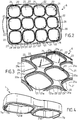
figure 1 est une vue en perspective éclatée d'un exemple de réalisation d'un appareil électrique pour chauffer des aliments en portions séparées comportant un accessoire de support pour la réalisation de préparations culinaires en portions séparées selon l'invention, - la
figure 2 est une vue en perspective de dessus d'un corps principal ajouré, appartenant à l'accessoire de support pour la réalisation de préparations culinaires en portions séparées selon l'invention illustré sur lafigure 1 , - la
figure 3 est une vue partielle en perspective selon une autre orientation du corps principal ajouré illustré sur lafigure 2 , - la
figure 4 est une vue en perspective de dessous d'un rehausseur appartenant à l'accessoire de support pour la réalisation de préparations culinaires en portions séparées selon l'invention illustré sur lafigure 1 , - La
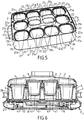
figure 5 est une vue en perspective de l'accessoire de support pour la réalisation de préparations culinaires en portions séparées selon l'invention en configuration assemblée, - La
figure 6 est une vue en élévation et en coupe longitudinale de l'appareil électrique pour chauffer des aliments en portions séparées illustré sur lafigure 1 , comportant l'accessoire de support pour la réalisation de préparations culinaires en portions séparées selon l'invention en configuration assemblée illustré sur lafigure 5 .
- the
figure 1 is an exploded perspective view of an exemplary embodiment of an electrical appliance for heating food in separate portions comprising a support accessory for making culinary preparations in separate portions according to the invention, - the
figure 2 is a perspective view from above of a perforated main body, belonging to the support accessory for the preparation of culinary preparations in separate portions according to the invention illustrated in FIG.figure 1 , - the
figure 3 is a partial perspective view in another orientation of the perforated main body illustrated infigure 2 , - the
figure 4 is a perspective view from below of a booster belonging to the support accessory for the production of culinary preparations in separate portions according to the invention illustrated onfigure 1 , - The
figure 5 is a perspective view of the support accessory for making culinary preparations in separate portions according to the invention in assembled configuration, - The
figure 6 is a view in elevation and in longitudinal section of the electric apparatus for heating food in separate portions illustrated infigure 1 , comprising the support accessory for the production of culinary preparations in separate portions according to the invention in assembled configuration illustrated onfigure 5 .
L'appareil électrique pour chauffer des aliments en portions séparées illustré sur les
Si désiré chacun des récipients 4 peut être associé à un couvercle 5. Tel que représenté sur la
L'appareil électrique pour chauffer des aliments en portions séparées illustré sur les
La base chauffante 1 comporte un dispositif de production de vapeur 8. La base chauffante 1 et l'accessoire de support 2 formant une enceinte 9 susceptible de contenir de la vapeur issue du dispositif de production de vapeur 8. La partie inférieure des récipients 4 portés par l'accessoire de support 2 s'étend dans l'enceinte 9.The
Dans l'exemple de réalisation illustré sur les
Si désiré, l'accessoire de support 2 et/ou le couvercle principal 3 peuvent comporter un ou plusieurs orifices d'échappement de vapeur 28 ; 30.If desired, the
Plus particulièrement dans l'exemple de réalisation illustré sur les
L'appareil électrique pour chauffer des aliments en portions séparées illustré sur les
Tel que visible sur la
Les orifices 21 comprennent des orifices périphériques 21a et au moins un orifice central 21b entouré par les orifices périphériques 21a. Les orifices 21 comprennent au moins six orifices périphériques 21a entourant au moins un orifice central 21b. Le bord supérieur d'appui 22 de l'orifice central 21b ou de l'un au moins des orifices centraux 21b est surélevé par rapport aux bords supérieurs d'appui 22 des orifices périphériques 21a.The
Dans l'exemple de réalisation illustré sur les figures, les orifices 21 comprennent des orifices inférieurs 21c et au moins un orifice supérieur 21d. Le bord supérieur d'appui 22 du ou de chaque orifice supérieur 21d est surélevé par rapport au bord supérieur d'appui de chaque orifice inférieur 21c.In the exemplary embodiment illustrated in the figures, the
Dans l'exemple de réalisation illustré sur les figures, l'accessoire de support 2 comporte douze orifices 21 recevant douze récipients 4. Si désiré, des couvercles 5 peuvent fermer les récipients 4. Tel que bien visible sur la
Plus particulièrement dans l'exemple de réalisation illustré sur les figures, l'accessoire de support 2 comprend un corps principal 6 et un rehausseur 7. Le corps principal 6 présente la majorité des orifices 21. Le corps principal 6 présente les orifices inférieurs 21c. Le rehausseur 7 présente les orifices supérieurs 21d.More particularly in the exemplary embodiment illustrated in the figures, the
Selon une forme de réalisation illustrée sur les figures, le rehausseur 7 est monté amovible par rapport au corps principal 6. Selon une forme de réalisation préférée illustrée sur les figures, le corps principal 6 présente au moins un orifice complémentaire 21e entouré par un bord supérieur d'appui complémentaire 22e. Si désiré, le rehausseur 7 repose sur le ou sur l'un au moins des bord(s) supérieur(s) d'appui complémentaire(s) 22e lorsque le rehausseur 7 est en place sur le corps principal 6. Le ou chaque bord supérieur d'appui complémentaire 22e est prévu pour suspendre un récipient 4 lorsque le rehausseur 7 n'est pas en place sur le corps principal 6. De préférence, les bords supérieurs d'appui 22 et le ou chaque bord supérieur d'appui complémentaire 22e s'étendent au même niveau.According to one embodiment illustrated in the figures, the
Tel que bien visible sur les
Le rehausseur 7 présente deux languettes inférieures 7b opposées prévues chacune pour être engagée dans l'un des orifices complémentaires 21e. A cet effet le rehausseur 7 présente deux protubérances 7a, dont l'une est visible sur la
Tel que mieux visible sur les
Tel que visible sur la
L'appareil électrique pour chauffer des aliments en portions séparées comportant l'accessoire de support 2 selon l'invention s'utilise et fonctionne de la manière suivante.The electric appliance for heating food in separate portions comprising the
L'utilisateur verse la quantité d'eau désirée dans la cavité 11, puis dispose l'accessoire de support 2 portant les récipients 4 sur la base chauffante 1. A cet effet l''épaulement 4a de chaque récipient 4 vient en appui sur le bord supérieur d'appui 22 de chaque orifice 21. L'utilisateur peut aussi mettre en place l'accessoire de support 2 sur la base chauffante 1, puis les récipients 4 dans les orifices 21 de l'accessoire de support 2. Sur la
L'utilisateur met ensuite en marche l'appareil électrique pour chauffer des aliments en portions séparées, pour alimenter électriquement le dispositif de chauffe 12 et évaporer l'eau contenue dans la cavité 11, pour chauffer les récipients 4 portés par l'accessoire de support 2, ainsi que la préparation alimentaire contenue dans les récipients 4. La vapeur ainsi obtenue peut remplir l'enceinte 9, l'air ou la vapeur pouvant si nécessaire s'échapper de l'enceinte 9 par un des orifices d'échappement de vapeur 28 de l'accessoire de support 2, ou par un des orifices d'échappement de vapeur 30 du couvercle 3 si le couvercle 3 est en place sur l'accessoire de support 2.The user then turns on the electrical appliance to heat food in separate portions, to electrically power the heating device.
Lorsque le rehausseur 7 est en place sur le corps principal 6, les récipients 4 disposés en position centrale sont davantage éloignés de la cavité 11 qu'en l'absence du rehausseur 7. Lorsque le rehausseur 7 est en place sur le corps principal 6, l'espace plus important sous le fond 41 des récipients 4 disposés en position centrale permet de favoriser une diffusion latérale de la vapeur vers le fond 41 des récipients 4 agencés en position périphérique. La vapeur atteint ainsi plus tardivement le fond des récipients 4 agencés en position centrale.When the
Ces dispositions permettent d'obtenir un appareil électrique pour chauffer des aliments en portions séparées, dans lequel la chauffe des récipients 4 à la vapeur peut être réalisée avec des écarts de température limités entre les récipients 4, notamment dans le cadre d'un processus de fermentation devant être effectué à une température inférieure à 50°C pour éviter de détruire les ferments lactiques, sans nécessiter un dispositif de production de vapeur 8 fournissant un flux de vapeur réparti de manière homogène sous le fond 41 des récipients 4.These arrangements make it possible to obtain an electrical appliance for heating food in separate portions, in which the heating of the
Si désiré, l'utilisateur peut retirer le rehausseur 7 du corps principal 6 et mettre en place des récipients 4 dans les orifices complémentaires 21e du corps principal, lorsque la préparation alimentaire à réaliser ne nécessite pas un contrôle précis de la température atteinte par les récipients 4, par l'exemple lors de la réalisation de certaines préparations culinaires nécessitant une cuisson d'aliments. Pour retirer le rehausseur 7 du corps principal 6, l'utilisateur peut exercer une pression à la base de l'une au moins des deux extrémités du rehausseur 7, au-dessus de l'une au moins des languettes inférieures 7b , pour déformer légèrement le rehausseur 7 de manière élastique, et dégager au moins une des protubérances 7a du bord supérieur d'appui complémentaire 22e correspondant, afin d'extraire au moins l'une des languettes inférieures 7b de l'orifice complémentaire 21e correspondant. Pour mettre en place le rehausseur 7, sur le corps principal 6, l'utilisateur peut par exemple mettre en place l'une des protubérances 7a dans l'une des échancrures 23, puis exercer une pression à la base de l'extrémité du rehausseur 7 opposée à la protubérance 7a déjà engagée, pour déformer légèrement le rehausseur 7 de manière élastique, et engager l'autre protubérance 7a dans l'orifice complémentaire 21e correspondant, puis dans l'échancrure 23 correspondante, après relâchement de la déformation élastique du rehausseur 7.If desired, the user can remove the
A titre de variante, l'accessoire de support 2 peut comporter un seul orifice central 21b, ou plus de deux orifices centraux 21b.As a variant, the
A titre de variante, l'accessoire de support 2 peut comporter un seul orifice supérieur 21d, ou plus de deux orifices supérieurs 21d.As a variant, the
A titre de variante, le ou chaque orifice supérieur 21d n'est pas nécessairement un orifice central 21b.As a variant, the or each
A titre de variante, le ou chaque orifice inférieur 21c n'est pas nécessairement un orifice périphérique 21a.As a variant, the or each
A titre de variante, le ou l'un au moins des orifices supérieurs 21d peut être agencé au moins partiellement au-dessus de la cavité 11, et de préférence être agencé principalement au-dessus de la cavité 11.As a variant, the or at least one of the
A titre de variante, la surface supérieure 20 de l'accessoire de support 2 peut comporter plus de deux niveaux présentant chacun au moins un des orifices 21.As a variant, the
A titre de variante, le rehausseur 7 peut présenter au moins un orifice supérieur 21d.As a variant, the
A titre de variante, le rehausseur 7 peut présenter une protubérance 7a prévue pour être engagée dans une échancrure 23 ménagée dans le bord supérieur d'appui complémentaire 22e lorsque le rehausseur 7 est en place sur le corps principal 6.As a variant, the
A titre de variante, le ou les orifices complémentaires 21e ne sont pas nécessairement prévus pour suspendre un récipient 4, mais peu(ven)t servir à retenir le rehausseur 7 monté sur le corps principal 6.As a variant, the complementary orifice (s) 21e are not necessarily provided to suspend a
A titre de variante, l'accessoire de support 2 ne comporte pas nécessairement un rehausseur 7 amovible par rapport à un corps principal 6.As a variant, the
A titre de variante, le dispositif de chauffe 12 peut notamment comporter des moyens de chauffage surfaciques s'étendant en dessous de seulement certains des récipients 4.As a variant, the
A titre de variante, le dispositif de production de vapeur 8 ne comporte pas nécessairement une cavité 11 ménagée dans l'enceinte 9. Le dispositif de production de vapeur 8 peut notamment comporter au moins une sortie de vapeur débouchant en dessous d'au moins un des récipients 4 et/ou entre certains des récipients 4.As a variant, the
La présente invention n'est nullement limitée à l'exemple de réalisation décrit et à ses variantes, mais englobe de nombreuses modifications dans le cadre des revendications.The present invention is in no way limited to the exemplary embodiment described and its variants, but encompasses numerous modifications within the scope of the claims.
Claims (14)
- Electrical apparatus for heating food divided into separate portions, comprising a heating base (1) comprising a steam-producing device (8), containers (4) for containing food to be heated, and a support accessory (2) for suspending the container (4) such that the bottom (41) of each container (4) is distant from the heating base (1) when the heating base (1) carries the support accessory (2), the heating base (1) and the support accessory (2) forming a chamber (9) which can contain steam from the steam-producing device (8), the support accessory (2) comprising an upper surface (20) having several orifices (21), each orifice (21) passing through the support accessory (2), each orifice (21) being surrounded by an upper support edge (22), each upper support edge (22) being provided to suspend a container (4), characterised in that the upper support edges (22) extend at different levels of the upper surface (20).
- Electrical apparatus for heating food divided into separate portions according to claim 1, characterised in that the orifices (21) comprise peripheral orifices (21a) and at least one central orifice (21b) surrounded by the peripheral orifices (21a).
- Electrical apparatus for heating food divided into separate portions according to claim 2, characterised in that the upper support edge (22) of the central orifice (21b) or of the at least one of the central orifices (21b) is raised with respect to the upper support edges (22) of the peripheral orifices (21a).
- Electrical apparatus for heating food divided into separate portions according to one of claims 2 or 3, characterised in that the orifices (21) comprise at least six peripheral orifices (21a) surrounding at least one central orifice (21b), and preferably ten peripheral orifices (21a) surrounding two central orifices (21b).
- Electrical apparatus for heating food divided into separate portions according to one of claims 1 to 4, characterised in that the orifices (21) comprise lower orifices (21c) and at least one upper orifice (21d), the upper support edge (22) of the or of each upper orifice (21d) being raised with respect to the upper support edge of each lower orifice (21c).
- Electrical apparatus for heating food divided into separate portions according to claim 5, characterised in that it comprises a main body (6) having the lower orifices (21c) and a booster (7) having said at least one upper orifice (21d).
- Electrical apparatus for heating food divided into separate portions according to claim 6, characterised in that the main body (6) has most of the orifices (21).
- Electrical apparatus for heating food divided into separate portions according to one of claims 6 or 7, characterised in that the booster (7) is removably mounted with respect to the main body (6).
- Electrical apparatus for heating food divided into separate portions according to claim 8, characterised in that the main body (6) has at least one complementary orifice (21e) surrounded by a complementary upper support edge (22e) provided to suspend a container (4) when the booster (7) is not in place on the main body (6).
- Electrical apparatus for heating food divided into separate portions according to claim 9, characterised in that the booster (7) rests on the complementary upper support edge (22e) when the booster (7) is in place on the main body (6).
- Electrical apparatus for heating food divided into separate portions according to one of claims 9 or 10, characterised in that the booster (7) has a protrusion (7a) provided to be engaged in an indentation (23) arranged in the complementary upper support edge (22e) when the booster (7) is in place on the main body (6).
- Electrical apparatus for heating food divided into separate portions according to claim 9, characterised in that the main body (6) comprises two complementary orifices (21e) each having a complementary upper support edge (22e) having an indentation (23), and in that the booster (7) has two protrusions (7a) each provided to be engaged in one of the indentations (23) when the booster (7) is in place on the main body (6).
- Electrical apparatus for heating food divided into separate portions according to claim 5, characterised in that the stream-producing device (8) comprises a cavity (11) provided to receive water, a heating device (12) for bringing the water contained in the cavity (11) to the boil, the cavity (11) being arranged in the chamber (9), the or at least one of the upper orifices (21d) being arranged at least partially above the cavity (11), and preferably mainly or fully above the cavity (11).
- Electrical apparatus for heating food divided into separate portions according to one of claims 1 to 13, characterised in that it forms a yogurt maker.
Applications Claiming Priority (1)
| Application Number | Priority Date | Filing Date | Title |
|---|---|---|---|
| FR1854493A FR3081308B1 (en) | 2018-05-28 | 2018-05-28 | SUPPORT ACCESSORY AND ELECTRIC APPARATUS FOR HEATING FOOD IN SEPARATE PORTIONS |
Publications (2)
| Publication Number | Publication Date |
|---|---|
| EP3574765A1 EP3574765A1 (en) | 2019-12-04 |
| EP3574765B1 true EP3574765B1 (en) | 2021-01-27 |
Family
ID=62816820
Family Applications (1)
| Application Number | Title | Priority Date | Filing Date |
|---|---|---|---|
| EP19173796.4A Active EP3574765B1 (en) | 2018-05-28 | 2019-05-10 | Support accessory and electrical apparatus for heating food in separate portions |
Country Status (3)
| Country | Link |
|---|---|
| EP (1) | EP3574765B1 (en) |
| CN (2) | CN110537574A (en) |
| FR (1) | FR3081308B1 (en) |
Families Citing this family (1)
| Publication number | Priority date | Publication date | Assignee | Title |
|---|---|---|---|---|
| EP4327662A1 (en) * | 2022-08-26 | 2024-02-28 | Arçelik Anonim Sirketi | A yogurt maker for making homogeneous yogurt |
Family Cites Families (5)
| Publication number | Priority date | Publication date | Assignee | Title |
|---|---|---|---|---|
| FR1048525A (en) | 1951-09-27 | 1953-12-22 | Yoghurt maker | |
| JP2008131923A (en) * | 2006-11-29 | 2008-06-12 | Shintokyo Kiyari:Kk | Frozen food tray and frozen food package |
| FR2956291B1 (en) * | 2010-02-16 | 2012-10-12 | Seb Sa | DOMESTIC YOGURT AND METHOD FOR THE QUICK MANUFACTURE OF YOGURT |
| FR2960141B1 (en) | 2010-05-18 | 2013-03-29 | Seb Sa | ELECTRIC APPARATUS PROVIDED FOR CARRYING OUT CULINARY PREPARATIONS IN SEPARATE PORTIONS |
| CN207168383U (en) * | 2017-02-20 | 2018-04-03 | 浙江康家宝炊具有限公司 | Steam incubator tray |
-
2018
- 2018-05-28 FR FR1854493A patent/FR3081308B1/en active Active
-
2019
- 2019-05-10 EP EP19173796.4A patent/EP3574765B1/en active Active
- 2019-05-27 CN CN201910446313.2A patent/CN110537574A/en active Pending
- 2019-05-27 CN CN201920772093.8U patent/CN210470875U/en active Active
Non-Patent Citations (1)
| Title |
|---|
| None * |
Also Published As
| Publication number | Publication date |
|---|---|
| EP3574765A1 (en) | 2019-12-04 |
| FR3081308A1 (en) | 2019-11-29 |
| CN110537574A (en) | 2019-12-06 |
| FR3081308B1 (en) | 2020-06-05 |
| CN210470875U (en) | 2020-05-08 |
Similar Documents
| Publication | Publication Date | Title |
|---|---|---|
| EP3558069B1 (en) | Accessory for steam-heating and/or -cooking food and steamer comprising a container and an accessory for steam-heating and/or -cooking food contained in the container | |
| EP3558071B1 (en) | Modular steamer accessory for steam-heating and/or -cooking food contained in a container | |
| CA3024856C (en) | Steamer accessory for steam-heating and/or steaming food in a container | |
| EP2571373B1 (en) | Electrical appliance provided for producing culinary preparations in separate portions | |
| EP1922967B1 (en) | Heating kitchen appliance comprising an intermediate cooking container | |
| EP3310217B1 (en) | Steam cooker accessory for steam heating and/or cooking foods contained in a container | |
| EP3574765B1 (en) | Support accessory and electrical apparatus for heating food in separate portions | |
| EP1343401B1 (en) | Utensil for slow-cook cycle steaming | |
| WO2008006971A2 (en) | Electrical appliance for making culinary preparations in separate portions | |
| EP2536316B1 (en) | Basket for an electrical appliance for steam-heating food or for a cooking utensil | |
| EP1555919B1 (en) | Vapour production base for steam cooker comprising an aromatic support | |
| EP2846642B1 (en) | Container for preparing liquid yoghurt in a yoghurt maker, and yoghurt maker comprising at least one such container | |
| EP2071985B1 (en) | Steam cooker with refilling system | |
| EP2574259B1 (en) | Steam cooker with device for filling the water tank during cooking | |
| FR2846216A1 (en) | Steam production base for steam cooker comprises boiling chamber located in case and aromatic support forming container heated by steam leaving boiling chamber | |
| EP2407070B1 (en) | Cooking apparatus, in particular for an electric cooking appliance |
Legal Events
| Date | Code | Title | Description |
|---|---|---|---|
| PUAI | Public reference made under article 153(3) epc to a published international application that has entered the european phase |
Free format text: ORIGINAL CODE: 0009012 |
|
| STAA | Information on the status of an ep patent application or granted ep patent |
Free format text: STATUS: THE APPLICATION HAS BEEN PUBLISHED |
|
| AK | Designated contracting states |
Kind code of ref document: A1 Designated state(s): AL AT BE BG CH CY CZ DE DK EE ES FI FR GB GR HR HU IE IS IT LI LT LU LV MC MK MT NL NO PL PT RO RS SE SI SK SM TR |
|
| AX | Request for extension of the european patent |
Extension state: BA ME |
|
| STAA | Information on the status of an ep patent application or granted ep patent |
Free format text: STATUS: REQUEST FOR EXAMINATION WAS MADE |
|
| 17P | Request for examination filed |
Effective date: 20200602 |
|
| RBV | Designated contracting states (corrected) |
Designated state(s): AL AT BE BG CH CY CZ DE DK EE ES FI FR GB GR HR HU IE IS IT LI LT LU LV MC MK MT NL NO PL PT RO RS SE SI SK SM TR |
|
| RIC1 | Information provided on ipc code assigned before grant |
Ipc: A23C 9/12 20060101AFI20200716BHEP Ipc: B65D 81/34 20060101ALI20200716BHEP |
|
| GRAP | Despatch of communication of intention to grant a patent |
Free format text: ORIGINAL CODE: EPIDOSNIGR1 |
|
| STAA | Information on the status of an ep patent application or granted ep patent |
Free format text: STATUS: GRANT OF PATENT IS INTENDED |
|
| INTG | Intention to grant announced |
Effective date: 20200916 |
|
| GRAS | Grant fee paid |
Free format text: ORIGINAL CODE: EPIDOSNIGR3 |
|
| GRAA | (expected) grant |
Free format text: ORIGINAL CODE: 0009210 |
|
| STAA | Information on the status of an ep patent application or granted ep patent |
Free format text: STATUS: THE PATENT HAS BEEN GRANTED |
|
| AK | Designated contracting states |
Kind code of ref document: B1 Designated state(s): AL AT BE BG CH CY CZ DE DK EE ES FI FR GB GR HR HU IE IS IT LI LT LU LV MC MK MT NL NO PL PT RO RS SE SI SK SM TR |
|
| REG | Reference to a national code |
Ref country code: GB Ref legal event code: FG4D Free format text: NOT ENGLISH |
|
| REG | Reference to a national code |
Ref country code: CH Ref legal event code: EP |
|
| REG | Reference to a national code |
Ref country code: AT Ref legal event code: REF Ref document number: 1357523 Country of ref document: AT Kind code of ref document: T Effective date: 20210215 |
|
| REG | Reference to a national code |
Ref country code: IE Ref legal event code: FG4D Free format text: LANGUAGE OF EP DOCUMENT: FRENCH |
|
| REG | Reference to a national code |
Ref country code: DE Ref legal event code: R096 Ref document number: 602019002329 Country of ref document: DE |
|
| REG | Reference to a national code |
Ref country code: NL Ref legal event code: MP Effective date: 20210127 |
|
| REG | Reference to a national code |
Ref country code: LT Ref legal event code: MG9D |
|
| REG | Reference to a national code |
Ref country code: AT Ref legal event code: MK05 Ref document number: 1357523 Country of ref document: AT Kind code of ref document: T Effective date: 20210127 |
|
| PG25 | Lapsed in a contracting state [announced via postgrant information from national office to epo] |
Ref country code: BG Free format text: LAPSE BECAUSE OF FAILURE TO SUBMIT A TRANSLATION OF THE DESCRIPTION OR TO PAY THE FEE WITHIN THE PRESCRIBED TIME-LIMIT Effective date: 20210427 Ref country code: FI Free format text: LAPSE BECAUSE OF FAILURE TO SUBMIT A TRANSLATION OF THE DESCRIPTION OR TO PAY THE FEE WITHIN THE PRESCRIBED TIME-LIMIT Effective date: 20210127 Ref country code: HR Free format text: LAPSE BECAUSE OF FAILURE TO SUBMIT A TRANSLATION OF THE DESCRIPTION OR TO PAY THE FEE WITHIN THE PRESCRIBED TIME-LIMIT Effective date: 20210127 Ref country code: GR Free format text: LAPSE BECAUSE OF FAILURE TO SUBMIT A TRANSLATION OF THE DESCRIPTION OR TO PAY THE FEE WITHIN THE PRESCRIBED TIME-LIMIT Effective date: 20210428 Ref country code: PT Free format text: LAPSE BECAUSE OF FAILURE TO SUBMIT A TRANSLATION OF THE DESCRIPTION OR TO PAY THE FEE WITHIN THE PRESCRIBED TIME-LIMIT Effective date: 20210527 Ref country code: NO Free format text: LAPSE BECAUSE OF FAILURE TO SUBMIT A TRANSLATION OF THE DESCRIPTION OR TO PAY THE FEE WITHIN THE PRESCRIBED TIME-LIMIT Effective date: 20210427 Ref country code: LT Free format text: LAPSE BECAUSE OF FAILURE TO SUBMIT A TRANSLATION OF THE DESCRIPTION OR TO PAY THE FEE WITHIN THE PRESCRIBED TIME-LIMIT Effective date: 20210127 |
|
| PG25 | Lapsed in a contracting state [announced via postgrant information from national office to epo] |
Ref country code: SE Free format text: LAPSE BECAUSE OF FAILURE TO SUBMIT A TRANSLATION OF THE DESCRIPTION OR TO PAY THE FEE WITHIN THE PRESCRIBED TIME-LIMIT Effective date: 20210127 Ref country code: AT Free format text: LAPSE BECAUSE OF FAILURE TO SUBMIT A TRANSLATION OF THE DESCRIPTION OR TO PAY THE FEE WITHIN THE PRESCRIBED TIME-LIMIT Effective date: 20210127 Ref country code: RS Free format text: LAPSE BECAUSE OF FAILURE TO SUBMIT A TRANSLATION OF THE DESCRIPTION OR TO PAY THE FEE WITHIN THE PRESCRIBED TIME-LIMIT Effective date: 20210127 Ref country code: PL Free format text: LAPSE BECAUSE OF FAILURE TO SUBMIT A TRANSLATION OF THE DESCRIPTION OR TO PAY THE FEE WITHIN THE PRESCRIBED TIME-LIMIT Effective date: 20210127 Ref country code: LV Free format text: LAPSE BECAUSE OF FAILURE TO SUBMIT A TRANSLATION OF THE DESCRIPTION OR TO PAY THE FEE WITHIN THE PRESCRIBED TIME-LIMIT Effective date: 20210127 |
|
| PG25 | Lapsed in a contracting state [announced via postgrant information from national office to epo] |
Ref country code: IS Free format text: LAPSE BECAUSE OF FAILURE TO SUBMIT A TRANSLATION OF THE DESCRIPTION OR TO PAY THE FEE WITHIN THE PRESCRIBED TIME-LIMIT Effective date: 20210527 |
|
| REG | Reference to a national code |
Ref country code: DE Ref legal event code: R097 Ref document number: 602019002329 Country of ref document: DE |
|
| PG25 | Lapsed in a contracting state [announced via postgrant information from national office to epo] |
Ref country code: EE Free format text: LAPSE BECAUSE OF FAILURE TO SUBMIT A TRANSLATION OF THE DESCRIPTION OR TO PAY THE FEE WITHIN THE PRESCRIBED TIME-LIMIT Effective date: 20210127 Ref country code: CZ Free format text: LAPSE BECAUSE OF FAILURE TO SUBMIT A TRANSLATION OF THE DESCRIPTION OR TO PAY THE FEE WITHIN THE PRESCRIBED TIME-LIMIT Effective date: 20210127 Ref country code: SM Free format text: LAPSE BECAUSE OF FAILURE TO SUBMIT A TRANSLATION OF THE DESCRIPTION OR TO PAY THE FEE WITHIN THE PRESCRIBED TIME-LIMIT Effective date: 20210127 |
|
| PG25 | Lapsed in a contracting state [announced via postgrant information from national office to epo] |
Ref country code: DK Free format text: LAPSE BECAUSE OF FAILURE TO SUBMIT A TRANSLATION OF THE DESCRIPTION OR TO PAY THE FEE WITHIN THE PRESCRIBED TIME-LIMIT Effective date: 20210127 Ref country code: RO Free format text: LAPSE BECAUSE OF FAILURE TO SUBMIT A TRANSLATION OF THE DESCRIPTION OR TO PAY THE FEE WITHIN THE PRESCRIBED TIME-LIMIT Effective date: 20210127 Ref country code: SK Free format text: LAPSE BECAUSE OF FAILURE TO SUBMIT A TRANSLATION OF THE DESCRIPTION OR TO PAY THE FEE WITHIN THE PRESCRIBED TIME-LIMIT Effective date: 20210127 |
|
| PLBE | No opposition filed within time limit |
Free format text: ORIGINAL CODE: 0009261 |
|
| STAA | Information on the status of an ep patent application or granted ep patent |
Free format text: STATUS: NO OPPOSITION FILED WITHIN TIME LIMIT |
|
| 26N | No opposition filed |
Effective date: 20211028 |
|
| PG25 | Lapsed in a contracting state [announced via postgrant information from national office to epo] |
Ref country code: ES Free format text: LAPSE BECAUSE OF FAILURE TO SUBMIT A TRANSLATION OF THE DESCRIPTION OR TO PAY THE FEE WITHIN THE PRESCRIBED TIME-LIMIT Effective date: 20210127 Ref country code: LU Free format text: LAPSE BECAUSE OF NON-PAYMENT OF DUE FEES Effective date: 20210510 Ref country code: AL Free format text: LAPSE BECAUSE OF FAILURE TO SUBMIT A TRANSLATION OF THE DESCRIPTION OR TO PAY THE FEE WITHIN THE PRESCRIBED TIME-LIMIT Effective date: 20210127 Ref country code: MC Free format text: LAPSE BECAUSE OF FAILURE TO SUBMIT A TRANSLATION OF THE DESCRIPTION OR TO PAY THE FEE WITHIN THE PRESCRIBED TIME-LIMIT Effective date: 20210127 |
|
| REG | Reference to a national code |
Ref country code: BE Ref legal event code: MM Effective date: 20210531 |
|
| PG25 | Lapsed in a contracting state [announced via postgrant information from national office to epo] |
Ref country code: SI Free format text: LAPSE BECAUSE OF FAILURE TO SUBMIT A TRANSLATION OF THE DESCRIPTION OR TO PAY THE FEE WITHIN THE PRESCRIBED TIME-LIMIT Effective date: 20210127 |
|
| PG25 | Lapsed in a contracting state [announced via postgrant information from national office to epo] |
Ref country code: IT Free format text: LAPSE BECAUSE OF FAILURE TO SUBMIT A TRANSLATION OF THE DESCRIPTION OR TO PAY THE FEE WITHIN THE PRESCRIBED TIME-LIMIT Effective date: 20210127 Ref country code: IE Free format text: LAPSE BECAUSE OF NON-PAYMENT OF DUE FEES Effective date: 20210510 |
|
| PG25 | Lapsed in a contracting state [announced via postgrant information from national office to epo] |
Ref country code: IS Free format text: LAPSE BECAUSE OF FAILURE TO SUBMIT A TRANSLATION OF THE DESCRIPTION OR TO PAY THE FEE WITHIN THE PRESCRIBED TIME-LIMIT Effective date: 20210527 |
|
| PG25 | Lapsed in a contracting state [announced via postgrant information from national office to epo] |
Ref country code: BE Free format text: LAPSE BECAUSE OF NON-PAYMENT OF DUE FEES Effective date: 20210531 |
|
| REG | Reference to a national code |
Ref country code: CH Ref legal event code: PL |
|
| PG25 | Lapsed in a contracting state [announced via postgrant information from national office to epo] |
Ref country code: LI Free format text: LAPSE BECAUSE OF NON-PAYMENT OF DUE FEES Effective date: 20220531 Ref country code: CH Free format text: LAPSE BECAUSE OF NON-PAYMENT OF DUE FEES Effective date: 20220531 |
|
| PG25 | Lapsed in a contracting state [announced via postgrant information from national office to epo] |
Ref country code: NL Free format text: LAPSE BECAUSE OF NON-PAYMENT OF DUE FEES Effective date: 20210127 Ref country code: CY Free format text: LAPSE BECAUSE OF FAILURE TO SUBMIT A TRANSLATION OF THE DESCRIPTION OR TO PAY THE FEE WITHIN THE PRESCRIBED TIME-LIMIT Effective date: 20210127 |
|
| PG25 | Lapsed in a contracting state [announced via postgrant information from national office to epo] |
Ref country code: HU Free format text: LAPSE BECAUSE OF FAILURE TO SUBMIT A TRANSLATION OF THE DESCRIPTION OR TO PAY THE FEE WITHIN THE PRESCRIBED TIME-LIMIT; INVALID AB INITIO Effective date: 20190510 |
|
| PGFP | Annual fee paid to national office [announced via postgrant information from national office to epo] |
Ref country code: FR Payment date: 20230523 Year of fee payment: 5 Ref country code: DE Payment date: 20230510 Year of fee payment: 5 |
|
| PGFP | Annual fee paid to national office [announced via postgrant information from national office to epo] |
Ref country code: GB Payment date: 20230519 Year of fee payment: 5 |