EP3574483B1 - Vorrichtung zum sortieren gebrauchter getränke- oder lebensmittelbehälter - Google Patents
Vorrichtung zum sortieren gebrauchter getränke- oder lebensmittelbehälter Download PDFInfo
- Publication number
- EP3574483B1 EP3574483B1 EP18702252.0A EP18702252A EP3574483B1 EP 3574483 B1 EP3574483 B1 EP 3574483B1 EP 18702252 A EP18702252 A EP 18702252A EP 3574483 B1 EP3574483 B1 EP 3574483B1
- Authority
- EP
- European Patent Office
- Prior art keywords
- sorting
- guiding
- cam
- containers
- drive member
- Prior art date
- Legal status (The legal status is an assumption and is not a legal conclusion. Google has not performed a legal analysis and makes no representation as to the accuracy of the status listed.)
- Active
Links
Images


Classifications
-
- G—PHYSICS
- G07—CHECKING-DEVICES
- G07F—COIN-FREED OR LIKE APPARATUS
- G07F11/00—Coin-freed apparatus for dispensing, or the like, discrete articles
- G07F11/007—Coin-freed apparatus for dispensing, or the like, discrete articles wherein the storage and dispensing mechanism are configurable in relation to the physical or geometrical properties of the articles to be stored or dispensed
-
- B—PERFORMING OPERATIONS; TRANSPORTING
- B07—SEPARATING SOLIDS FROM SOLIDS; SORTING
- B07C—POSTAL SORTING; SORTING INDIVIDUAL ARTICLES, OR BULK MATERIAL FIT TO BE SORTED PIECE-MEAL, e.g. BY PICKING
- B07C5/00—Sorting according to a characteristic or feature of the articles or material being sorted, e.g. by control effected by devices which detect or measure such characteristic or feature; Sorting by manually actuated devices, e.g. switches
- B07C5/04—Sorting according to size
- B07C5/12—Sorting according to size characterised by the application to particular articles, not otherwise provided for
- B07C5/122—Sorting according to size characterised by the application to particular articles, not otherwise provided for for bottles, ampoules, jars and other glassware
-
- B—PERFORMING OPERATIONS; TRANSPORTING
- B07—SEPARATING SOLIDS FROM SOLIDS; SORTING
- B07C—POSTAL SORTING; SORTING INDIVIDUAL ARTICLES, OR BULK MATERIAL FIT TO BE SORTED PIECE-MEAL, e.g. BY PICKING
- B07C5/00—Sorting according to a characteristic or feature of the articles or material being sorted, e.g. by control effected by devices which detect or measure such characteristic or feature; Sorting by manually actuated devices, e.g. switches
- B07C5/36—Sorting apparatus characterised by the means used for distribution
-
- B—PERFORMING OPERATIONS; TRANSPORTING
- B65—CONVEYING; PACKING; STORING; HANDLING THIN OR FILAMENTARY MATERIAL
- B65G—TRANSPORT OR STORAGE DEVICES, e.g. CONVEYORS FOR LOADING OR TIPPING, SHOP CONVEYOR SYSTEMS OR PNEUMATIC TUBE CONVEYORS
- B65G47/00—Article or material-handling devices associated with conveyors; Methods employing such devices
- B65G47/74—Feeding, transfer, or discharging devices of particular kinds or types
- B65G47/76—Fixed or adjustable ploughs or transverse scrapers
- B65G47/766—Adjustable ploughs or transverse scrapers
-
- G—PHYSICS
- G07—CHECKING-DEVICES
- G07F—COIN-FREED OR LIKE APPARATUS
- G07F7/00—Mechanisms actuated by objects other than coins to free or to actuate vending, hiring, coin or paper currency dispensing or refunding apparatus
- G07F7/06—Mechanisms actuated by objects other than coins to free or to actuate vending, hiring, coin or paper currency dispensing or refunding apparatus by returnable containers, i.e. reverse vending systems in which a user is rewarded for returning a container that serves as a token of value, e.g. bottles
-
- B—PERFORMING OPERATIONS; TRANSPORTING
- B65—CONVEYING; PACKING; STORING; HANDLING THIN OR FILAMENTARY MATERIAL
- B65G—TRANSPORT OR STORAGE DEVICES, e.g. CONVEYORS FOR LOADING OR TIPPING, SHOP CONVEYOR SYSTEMS OR PNEUMATIC TUBE CONVEYORS
- B65G2201/00—Indexing codes relating to handling devices, e.g. conveyors, characterised by the type of product or load being conveyed or handled
- B65G2201/02—Articles
- B65G2201/0235—Containers
- B65G2201/0244—Bottles
Definitions
- the present disclosure relates to a device for sorting objects, such as used beverage or food containers, that are conveyed on a conveyor.
- Devices for sorting objects may be used in reverse vending machines in e.g. super markets.
- sorting devices are arranged to sort received objects in three directions.
- EP1276684 B1 An example of a device adapted for sorting objects, such as used beverage or food containers, that are conveyed on a conveyor, is disclosed in EP1276684 B1 .
- This document discloses a device where objects conveyed on a conveyor belt are sorted by a channel-like gate which is pivotable about a vertical axis.
- the gate has two parallel side walls and is arranged to guide an object sideways relative to the longitudinal direction of the conveyor belt and, in a neutral position, to allow the object to pass unaffected by the gate.
- An actuator which may turn the gate towards one side or another of the conveyor belt is connected to the gate.
- This device is however bulky and space consuming.
- GB 1 397 017 A relates to an apparatus having a conveyor on which articles are transported, and for distributing articles arriving along a supply path to at least two delivery paths by deflecting the articles using a triangular-shaped deflector which is pivotable around an axis.
- the lever may be controlled via a spring, allowing it to make controlled movements.
- the deflector may be controlled via drive means.
- Each delivery path on the conveyor can, if desired, constitute a secondary supply path which leads to a further deflector of the aforementioned kind for distributing the articles arriving from the secondary supply path to respective secondary delivery paths.
- US 2009/078617 A1 relates to a device for directionally guiding articles of different shapes that are being conveyed on a conveyor off the conveyor using a movable gate that is controllable to move across the conveyor at an angle to the direction of travel of the article on the conveyor.
- the gate is made having a means which, upon movement across the conveyor, is designed to forcibly cause the article to be driven along the gate, in a direction corresponding to said angle, off the conveyor and to an exit.
- a device for sorting objects such as used beverage or food containers that are conveyed on a conveyor, the device being configured to sort at least two types of objects
- the device comprises a first guiding member which is pivotable about a first pivot axis and configured to, when the sorting device is situated in a first sorting position, guide objects or containers in a first direction, a second guiding member which is pivotable about a second pivot axis, a rotatable drive member, a first cam mechanism interconnecting the rotatable drive member with the first guiding member, and a second cam mechanism interconnecting the rotatable drive member with the second guiding member, wherein the device is configured to, upon rotation of the drive member, be actuated between said first sorting position and a second sorting position.
- the device thus comprises two separate guiding members, each of which may have a guiding surface.
- a laterally compact device yet enabling objects or containers to be sorted in three different directions, can be provided.
- the device can thus be made less bulky compared to prior art devices for sorting objects.
- the first and second cam mechanisms which together form a cam device for controlling pivotal movement of the first and second guiding members, allows the sorting device to be operated by one single actuator, such as a motor, via the drive member and thus provides for a compact and cost-efficient device.
- the drive member comprises a movable or rotatable element, in the form of e.g. a rotatable plate, which is fixedly mounted to e.g. a drive shaft.
- the drive shaft may be connected to an actuator, such as e.g. a motor.
- the drive member is e.g. configured to perform a partial rotation in any direction.
- the actuator is e.g. capable of rotating the drive member in the clockwise direction and in the anti-clockwise direction
- the sorting device may be used to sort containers in a single sorting direction, in two sorting directions or in three sorting directions.
- the sorting device may e.g. be used for sorting objects in a reverse vending machine configured for receiving and processing containers of a single type, containers of two types or containers of three types, thereby providing flexibility.
- first and second guiding members are configured to, upon rotation of the drive member, pivot one by one about the first and second pivot axes, respectively.
- shape of a cam of the first cam mechanism and the shape of a cam of the second cam mechanism are thus configured such that the first and second guiding members, upon rotation of the drive member, are pivoted one by one about the first and second pivot axes, respectively.
- first and second guiding members are configured to, upon rotation of the drive member, pivot simultaneously about the first and second pivot axes, respectively.
- shape of a cam of the first cam mechanism and the shape of a cam of the second cam mechanism are thus configured such that the first and second guiding members, upon rotation of the drive member, are pivoted simultaneously about the first and second pivot axes, respectively.
- the first and second guiding members are configured to, upon rotation of the drive member, pivot partly simultaneously about the first and second pivot axes, respectively.
- the expression “partly simultaneously” means that, when the sorting device is actuated/moved from one sorting position to another sorting position, both guiding members are pivoted simultaneously during a part of the actuation and during another part of the actuation one single guiding member is pivoted. For instance, during a first part of the movement of the sorting device from a first sorting position to a second sorting position, both guiding members are pivoted and during a subsequent part of the movement only one guiding member is pivoted.
- one of the guiding members makes a full rotational displacement, e.g. 35 or 40 degrees, and the other guiding member makes a minor rotational displacement, e.g. a few degrees or between 2° and 7°, when the sorting device is moved between two sorting positions. For instance, this can be used when a larger passage for containers is desired when the bottles are redirected..
- containers are allowed to continue in the direction of travel of the conveyor or are guided in a direction being different from said first sorting direction when the device is situated in said second sorting position.
- the second guiding member is configured to guide containers in a second sorting direction when the sorting device is situated in said second sorting position.
- the drive member may be rotatable at least 40°, or at least 60°, or at least 80°, or at least 100°, or at least 120°; when rotated from one end position to the other. Additionally, or alternatively, the drive member may be rotatable at most 140°, or at most 120°, or at most 100°, or at most 80°; when rotated from one end position to the other.
- the angle by which the drive member is rotatable is within the range of 60°-120°.
- the angle of deflection of the first guiding member may be at least 15°, or at least 20°, or at least 25°, or at least 30°, or at least 35°. Additionally, or alternatively, the angle of deflection of the first guiding member may be at most 55°, or at most 50°, or at most 45°, or at most 40°, or at most 35°. According to one embodiment the angle of deflection of the first guiding member is within the range of 25°-45°.
- the angle of deflection of a guiding member is the pivotation of the a guiding member when moved between a neutral poisition and a guiding position the first and the third sorting position.
- the neutral position of a guiding member refers to the position wherein the direction of the transported containers are unaffacted or substantially unaffacted by the guiding member; and the expression “the guiding position of a guiding member” refers to the position wherein the transported containers are guided and/or redirected by the guiding member.
- the angle of deflection of the second guiding member may be at least 15°, or at least 20°, or at least 25°, or at least 30°, or at least 35°. Additionally, or alternatively, the angle of deflection of the second guiding member may be at most 55°, or at most 50°, or at most 45°, or at most 40°, or at most 35°.
- the angle of deflection of the second guiding member is the pivotation of the second guiding member when the sorting device is situated in the second sorting position. According to one embodiment the angle of deflection of the second guiding member is within the range of 25°-45°.
- said first and second sorting directions are opposite to each other.
- containers may thus be guided in opposite directions and away from each other.
- the device may assume a third sorting position.
- said third sorting position is an intermediate sorting position in which containers are allowed to continue in the direction of travel of the conveyor.
- At least one of the first and second cam mechanisms comprises a cam that forms a part of one of said guiding members and a cam follower that forms a part of the drive member.
- the first cam mechanism comprises a first cam groove and a first cam follower received in the first cam groove
- the second cam mechanism comprises a second cam groove and a second cam follower received in the second cam groove
- At least one of said cam followers forms a part of the drive member.
- one of said cam grooves is formed in a part of one of the first and second guiding members and preferably the other one of said cam grooves is formed in a part of the other one of the first and second guiding members.
- At least one of said cam followers comprises a roller assembly. This embodiment has the advantage that friction losses may be reduced.
- At least one of the guiding members comprises a guiding plate.
- Each guiding member may have at least two positions, namely a passive position in which the guiding member is arranged to the side of the conveyor, without crossing the conveyor, and an active position in which the guiding member is arranged across the conveyor so objects are guided to the side of the conveyor.
- each guiding plate may have at least two positions, namely a passive position in which the guiding plate is arranged to the side of the conveyor, without crossing the conveyor, and an active position in which the guiding plate is arranged across the conveyor so objects are guided to the side of the conveyor.
- a guiding member or a guiding plate which is arranged in the passive position does not take part in the guiding of the objects and/or objects may pass the guiding member without being brought into contact therewith.
- one, some or all of the objects may touch the guiding plate when the plate is arranged in the passive position - however, this will not cause any substatial redirection of the object from its incomming path of transportation.
- the first guiding member and/or a first guiding plate are/is arranged in the active position and the second guiding member and/or a second guiding plate are/is arranged in the passive position.
- the first guiding member and/or the first guiding plate are/is arranged in the passive position and the second guiding member and/or the second guiding plate are/is arranged in the active position.
- the first and the second guiding members are arranged in their respective passive positions and/or the first and the second guiding plates are arranged in their respective passive positions.
- the spatial position of a guiding member and/or a guiding plate may differ, when comparing the passive position used when objects are guided to the side, as compared to the passive position used when the device is arranged in the intermediate position. I.e. there are two different positions in which a guiding member and/or a guiding plate may be arranged, one for the intermediate position and one for the sorting position, and both being passive positions.
- the spatial position of a guiding member and/or a guiding plate is the same, when comparing the passive position used when objects are guided to the side, as compared to the passive position used when the device is arranged in the intermediate position.
- At least one of the guiding members comprises a curved guiding plate.
- the device comprises an actuator, such as e.g. a motor, for rotating the rotatable drive member.
- an actuator such as e.g. a motor
- one single actuator is connected to the drive member, said actuator being capable of rotating the drive member in the clockwise direction and in the anti-clockwise direction.
- said one single actuator is a motor.
- a device for sorting objects such as used beverage or food containers, that are conveyed on a conveyor
- the device comprises one single guiding member which is pivotable about a pivot axis and configured to, when the sorting device is situated in a first sorting position, guide containers in a first sorting direction; a rotatable drive member; a cam mechanism interconnecting the rotatable drive member with the guiding member; wherein the device is configured to, upon rotation of the drive member, be actuated between said first sorting position and a second sorting position.
- This singel guide sorting device may be used in combination with the dual guide sorting device decribed above. Accroding to one example the objects first passes and/or is directed by the dual guide sorting device in a desired direction; further downstream in the transportation path the object passes and/or is directed by the single guide sorting device, which can be arranged in a first or second sorting position.
- the sigle and dual guide sorting devices may by controlled indiviually, each having a separate drive member.
- the single guide sorting device may also be arranged upstream of the dual guide sorting device; and the single guide sorting device may also be used on its own, i.e. without a dual sorting device being present in the transportation path.
- the guiding member may be provided with a guiding plate, and these may each be arranged in both an active and passive position.
- the guiding member When the guiding member is arranged in the passive position, the object continues along the incoming transportation path, and when the guiding member is arranged in the active position the direction of object is altered.
- the single guide sorting device is controlled in the same way as explained in realation to the dual guide sorting device except that there is no second guiding member and/or no second guiding plate - i.e. there is only one guiding member and/or only one guiding plate - so the rotateable drive member and the cam mechanism etc. are configured to act only on one guide member and/or one guiding plate.
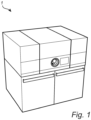
- Fig. 1 shows a reverse vending machine 1 for receiving, sorting and processing of objects, such as used food and/or beverage containers.
- the reverse vending machine 1 may be located in e.g. a local store, a residential area or a car park, for receiving and processing used beverage and/or food containers from consumers.
- the reverse vending machine 1 is provided with a device for sorting objects according to an embodiment of the present disclosure.
- a reverse vending machine provided with a sorting device may be configured to receive and process one single type of containers, e.g. metal containers, two types of containers, e.g. metal containers and plastic containers, or three types of containers, e.g. metal containers, plastic containers and glass containers.
- one single type of containers e.g. metal containers
- two types of containers e.g. metal containers and plastic containers
- three types of containers e.g. metal containers, plastic containers and glass containers.
- the reverse vending machine 1 comprises an inlet opening 3, a conveyor 5, a sorting device 7, a first container crushing device 9 and a second container crushing device 11.
- the first container crushing device 9 may be adapted for crushing metal cans and the second container crushing device 11 may be adapted for crushing plastic bottles.
- the reverse vending machine 1 is thus configured to receive and process containers of two types of materials.
- guiding member and sorting member are used interchangeably.
- idle sorting position and intermediate sorting position are used interchangeably, and denotes the sorting position where the objects continue along the incoming transportation path.
- the sorting device 7 is arranged to sort containers, which are received through the inlet opening 3 and conveyed by the conveyor 5, either to the first crushing device 9, to the second crushing device 11 or straight through to a trash collector (not shown).
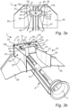
- the sorting device 7 comprises a first pivotable guiding member 13, a second pivotable sorting member 15 and a rotatable drive member 17 arranged to operate each of the first and second guiding members 13, 15.
- the drive member 17, which is rotatable in the clockwise direction and in the anti-clockwise direction by an actuator (not shown), is arranged to drive the sorting members 13, 15 between different sorting positions of the sorting device 7.
- the sorting device 7 is situated in an idle sorting position, also referred to as a second or a third sorting position, in which the guiding members 13, 15 are separated from each other and allow containers 14 conveyed by the conveyor 5 to pass straight through the sorting device 7 to a rear part of the machine 1, as illustrated by arrows in Fig. 3b .
- containers in the idle sorting position containers continue in the direction of travel of the conveyor 5 or along the incoming transportation path as illustrated by the arrow, and may thus be forwarded to a collector (not shown) situated downstream of the sorting device 7.
- the conveyor 5 is a V conveyor.
- the conveyor may be a flat conveyor.
- the conveyor 5 may comprise one or several conveyor belts.
- a stationary guide device 55 comprising two guide plates are arranged to guide containers sorted by the sorting device 7 to any of the crushing devices 9, 11.
- the reverse vending machine 1 further comprises an inspection means (not shown) for identifying containers received through the inlet opening 3.
- This inspection means which is situated upstream of the sorting device 7, is capable of identifying the material of a container received through the inlet opening 3. Based on the information obtained by the inspection means the sorting device 7 may be driven to an appropriate sorting position to guide the identified container to the left or right, or to allow the container to continue straight ahead.
- each of the sorting device 7 and the inspection means is connected to a control unit (not shown) of the machine 1.
- the inspection means may be a camera or a scanner, such as a bar code reader.
- the first sorting member 13 of the sorting device 7 is at one end 13a pivotally arranged by means of a pivot shaft 19 which is connected to a support structure 21.
- the support structure 21 may be secured to a frame part (not shown) of the reverse vending machine 1.
- the first pivot shaft 19 defines a first pivot axis 23.
- the second sorting member 15 of the sorting device device 7 is at one end 15a pivotally arranged by means of a second pivot shaft 25 which is connected to the support structure 21.
- the second pivot shaft 25 defines a second pivot axis 27.
- the first guiding member 13 comprises a first guiding element, in the form of a first guiding plate 29, and a cam element in the form of a cam plate 31.
- a first cam in the form of a first curved cam groove 33, is formed in the first cam plate 31.
- the curvature of the first cam groove 33 is adapted to control pivotal movement of the first guiding member 13.
- the second guiding member 15 comprises a second guiding element, in the form of a second guiding plate 35, and a second cam element in the form of a second cam plate 37.
- a second cam in the form of a second curved cam groove 39, is formed in the second cam plate 37. The curvature of the second cam groove is adapted to control pivotal movement of the second guiding member 15.
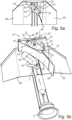
- the first guiding plate 29 forms a first guiding surface 41 which is configured to, when the sorting device 7 is situated in a first sorting position, guide containers 16 to the right, as illustrated by arrow C in Fig. 4b .
- the second guiding plate 35 forms a second guiding surface 43 which is configured to, when the sorting device 7 is situated in a second sorting position, guide containers 18 to the left, as illustrated by arrow F in Fig. 5b .
- Each of the first and second guiding surface 41, 43 is thus configured to guide containers conveyed on the conveyor 5 laterally or away from the incomming transportation path.
- the first and second guiding surfaces 41, 43 are facing away from each other.
- the drive member 17 comprises a rotatable element, in the form of a rotatable plate 45, which is fixedly mounted to a drive shaft 47.
- the drive shaft 47 is connected to an actuator (not shown), such as e.g. a motor, and defines a third pivot axis 49.
- the drive member 17 is configured to perform a partial rotation in any direction.
- the actuator is capable of rotating the drive member 17 in the clockwise direction and in the anti-clockwise direction.
- the drive plate 45 is at one side of the pivot axis 49 provided with a first cam follower, in the form of a first cam follower roller 51, and at an opposite side of the third pivot axis 49 provided with a second cam follower in the form of a second cam follower roller 53.
- Each of the first and second cam follower rollers 51, 53 is thus located at a distance from the third pivot axis 49.
- the first cam follower roller 51 is received in the first cam groove 33, which is formed in the first cam plate 31, and the second cam follower roller 53 is received in the second cam groove 39 which is formed in the second cam plate 37.
- Fig. 4a which illustrates the sorting device 7 in the first sorting position
- the drive member 17 has been rotated anti-clockwise about the third pivot axis 49, as illustrated by arrow A.
- This rotation of the drive member 17 causes the first cam follower roller 51 to travel in the first cam groove 33 and the second cam follower roller 53 to travel in the second cam groove 39, as illustrated by arrows B, and the first guiding member 13 to pivot about the first pivot axis 23.
- the sorting device 7 Upon actuation of the sorting device 7 from the intermediate sorting position ( Fig. 3a ) to the first sorting position ( Fig.
- the drive member 17 is rotated approximately 40 degrees anti-clockwise about the third pivot axis 49, which causes the first guiding member 13 to pivot approximately 36 degrees about the first pivot axis 23, i.e. to deflect about 36 degrees.
- the angle of deflection of the first guiding member 13 is thus approximately 36 degrees.
- the second guiding member 15 is not pivoted and thus maintains its position.
- the first guiding surface 41 guides containers 16, such as cans, to the right, as illustrated by arrow C, to be forwarded to the first crushing device 9 by the stationary guide plate 55.
- the second guiding plate 35 has slightly different angular positions when the sorting device is arranged in the idle sorting position ( Fig 3 ) as compared to the first sorting position ( Fig 4 ); but the second guiding plate 35 is still arranged in the passive position to the side of the incomming transportation path both in Fig 3 and Fig 4 .
- the second guiding member 15 may have slightly different angular positions when the sorting device is arranged in the idle sorting position ( Fig 3 ) as compared to the first sorting position ( Fig 4 ); but the second guiding member 15 is still arranged in the passive position both in Fig 3 and Fig 4 .
- Fig. 5a which illustrates the sorting device 7 in the second sorting position
- the drive member 17 has been rotated clock-clockwise about the third pivot axis 49, as illustrated by arrow D.
- This rotation of the drive member 17 causes the first cam follower roller 51 to travel in the first cam groove 37 of the first cam plate 31 and the second cam follower roller 53 to travel in the second cam groove 39 of the second cam plate 37, as illustrated by arrows E, and the second guiding member 15 to pivot about the second pivot axis 27.
- the sorting device 7 Upon actuation of the sorting device 7 from the intermediate sorting position ( Fig. 3a ) to the second sorting position ( Fig.
- the drive member 17 is rotated approximately 40 degrees clockwise about the third pivot axis 49, which causes the second guiding member 13 to pivot approximately 36 degrees about the second pivot axis 27, i.e. to deflect about 36 degrees.
- the angle of deflection of the second guiding member 15 is thus approximately 36 degrees.
- the first guiding member 13 is not pivoted and thus maintains its position.
- the second guiding surface 43 directs containers 18, such as plastic bottles, to the left, as illustrated by arrow F, to be forwarded to the second crushing device 11 by the stationary guide plate 55.
- the first and second cam grooves 33, 39 are thus configured to, upon rotation of the drive member 17, control the pivotal movement of the first and second guiding members 13, 15. Upon rotation of the drive member 17, the first and second guiding plates 29, 35 are pivoted one by one under the guidance of the first and second cam mechanisms.
- the first and second guiding plates 29, 35 are pivoted simultaneously under the guidance of the first and second cam mechanisms.
- the curvature of the first cam groove 33 and the curvature of the second cam groove 39 may thus be adapted such that the first and second guiding members 13, 15, upon rotation of the drive member 17, are pivoted one by one or simultaneously or partly simultaneously about the first and second pivot axes 23, 27, respectively.
- the sorting device 7 of the present disclosure thus comprises two separate guiding members 13, 15, each of which has a guiding element 29, 25, which are controlled by a cam device and a single actuator.
- the first cam plate 31, in which the first cam groove 33 is formed forms together with the first cam follower 51 a first cam mechanism and the second cam plate 37, in which the second cam groove 39 is formed, forms together with the second cam follower 53 a second cam mechanism.
- the first and second cam mechanisms together form a cam device that, upon rotation of the drive member 17, causes the first and second guiding members 13, 15 to pivot one by one.
- the sorting device 7 When the sorting device 7 is actuated from the first sorting position to the second sorting position the first sorting member 13 is first pivoted. Then, i.e. when the first sorting member 13 has been pivoted, the second sorting member 15 is pivoted. Upon actuation of the sorting device 7 from the first sorting position to the second sorting position, the idle sorting position is thus passed. The idle sorting position is thus an intermediate sorting position and the direction of travel of the conveyor 5 forms a third sorting direction. Upon actuation of the sorting device 7 from the first sorting position ( Fig. 4a ) to the second sorting position ( Fig.
- the drive member 17 is rotated approximately 80 degrees clockwise about the third pivot axis 49, which first causes the second guiding member 13 to pivot approximately 36 degrees about the second pivot axis 27 and then the first guiding member 13 to pivot approximately 36 degrees about the first pivot axis 23.
- the drive member 17 Upon actuation of the sorting device 7 between the first sorting position and the second sorting position the drive member 17 does not perform a full rotation but a partial rotation.
- the reverse vending machine 1 is configured to receive and process metal containers and plastic containers. Containers that cannot be proaccessed in the first crushing device 9 or in the second crushing device 11, which are illustrated by a glass container 14 in Fig. 3b , are allowed to continue straight to e.g. a collector (not shown).
- the sorting device 7 is thus in this case arranged to guide containers 16 to the right, guide containers 18 to the left and allow containers 14 to continue in the direction of travel of the conveyor 5.
- the sorting device 7 may be used in a machine configured to receive and process containers of a single type, such as metal containers or plastic containers. Then, the sorting device may be arranged to guide containers in a first sorting direction, e.g. to the right. Received containers that are not to be sorted in the first sorting direction may be allowed to continue in the direction of travel of the conveyor 5. In this case, the idle sorting position, illustrated in Fig. 3a , forms a second sorting position and the direction of travel of the conveyor 5 forms a second sorting direction.
- a shorter rotation of the drive member is sufficient e.g. about half of the rotation needed compared to when the sorting device provides three sorting directions.
- the sorting device 7 may be used in a machine configured to receive and process containers of three types of containers, such as metal containers, plastic containers and glass containers. Then, the sorting device may be arranged in the same manner as illustrated hereinabove with reference to Figs. 3a-b , Figs. 4a-b and Figs. 5a-b , i.e. to guide metal containers 16 in a first sorting direction, e.g. to the right, guide plastic containers 18 in a second sorting direction, e.g. to the left, and, when the sorting device 7 is situated in a third sorting position, allow glass containers 14 to continue in a third sorting direction, which corresponds to the direction of travel of the conveyor 5, to a glass container processing device.
- a sorting device may thus be used for sorting objects in a reverse vending machine configured for receiving and processing containers of a single type, two types or three types.
- the design of the guiding element of the guiding members may be given different designs depending on e.g. material, size, shape and weight of the containers that the sorting device is to be able to handle. Guided by this description and possibly in combination with some testing the person skilled in the art will be able to find a suitable design.
- each of the cam mechanisms comprises a cam follower which is secured to the drive member and a cam plate provided with a cam. It is however appreciated that one or both cams may be formed as a part of the drive member and that cam follower(s) may be form a part of one or both of the guiding members.
- cam mechanisms may comprise sliding cam followers instead of rolling cam followers or a combination thereof.
- a guiding element such as a guiding plate, of each of the first and second guiding members may be curved.
- a guiding element may be planar.
Landscapes
- Physics & Mathematics (AREA)
- General Physics & Mathematics (AREA)
- Engineering & Computer Science (AREA)
- Mechanical Engineering (AREA)
- Sorting Of Articles (AREA)
- Discharge Of Articles From Conveyors (AREA)
Claims (17)
- Vorrichtung (7) zum Sortieren von Gegenständen, wie zum Beispiel gebrauchten Getränke- oder Lebensmittelbehältern (14, 16, 18), welche auf einem Transportband (5) gefördert werden, wobei die Vorrichtung (7) dafür eingerichtet ist, mindestens zwei Arten von Gegenständen zu sortieren,
dadurch gekennzeichnet, dassdie Vorrichtung (7) aufweist:
ein erstes Führungselement (13), welches um eine erste Schwenkachse (23) schwenkbar ist, und welches dafür eingerichtet ist, Behälter (16) in eine erste Sortierrichtung zu lenken, wenn die Sortiervorrichtung (7) in einer ersten Sortierposition angeordnet ist,ein zweites Führungselement (15), welches um eine zweite Schwenkachse (27) schwenkbar ist,ein drehbares Antriebselement (17),einen ersten Nockenmechanismus (31, 33, 51), welcher das drehbare Antriebselement (17) mit dem ersten Führungselement (13) verbindet, undeinen zweiten Nockenmechanismus (37, 39, 53), welcher das drehbare Antriebselement (17) mit dem zweiten Führungselement (15) verbindet,wobei die Vorrichtung (7) dafür eingerichtet ist, beim Drehen des Antriebselements (17) zwischen der ersten Sortierposition und einer zweiten Sortierposition betätigt zu werden. - Vorrichtung (7) nach Anspruch 1, wobei das erste und das zweite Führungselement (13, 15) dafür eingerichtet sind, beim Drehen des Antriebselements (17) eines nach dem anderen geschwenkt zu werden.
- Vorrichtung (7) nach einem der vorstehenden Ansprüche, wobei sich die Behälter (14, 18), wenn die Vorrichtung (7) in der zweiten Sortierposition angeordnet sind, in der Bewegungsrichtung des Transportbands (5) weiterbewegen können oder in eine Richtung gelenkt werden, welche sich von der ersten Sortierrichtung unterscheidet.
- Vorrichtung (7) nach Anspruch 1, wobei das zweite Führungselement (15) dafür eingerichtet ist, Behälter (16) in eine zweite Sortierrichtung zu lenken, wenn die Sortiervorrichtung (7) in der zweiten Sortierposition angeordnet ist.
- Vorrichtung (7) nach Anspruch 4, wobei die erste und die zweite Sortierrichtung einander entgegensetzt sind.
- Vorrichtung (7) nach einem der vorstehenden Ansprüche, wobei die Vorrichtung (7) eine dritte Sortierposition einnehmen kann.
- Vorrichtung (7) nach Anspruch 6, wobei die dritte Sortierposition eine mittlere Sortierposition ist, in welcher Behälter (14) in der Bewegungsrichtung des Transportbands (5) weiterbewegt werden können.
- Vorrichtung (7) nach einem der vorstehenden Ansprüche, wobei mindestens einer der Nockenmechanismen aus der Gruppe umfassend den ersten und den zweiten Nockenmechanismus (13, 15) eine Nocke (33, 37), welche einen Teil des mindestens einen (13, 15) Führungselements (13, 15) bildet, und einen Nockenläufer (51, 53), welcher einen Teil des Antriebselements (17) bildet, aufweist.
- Vorrichtung (7) nach einem der vorstehenden Ansprüche, wobei der erste Nockenmechanismus (31, 33, 51) eine erste Nockennut (33) und einen ersten Nockenläufer (51), welcher in der ersten Nockennut (33) aufgenommen ist, aufweist, und der zweite Nockenmechanismus (37, 39, 53) eine zweite Nockennut (37) und einen zweiten Nockenläufer (53), welcher in der zweiten Nockennut (37) aufgenommen ist, aufweist.
- Vorrichtung (1) nach Anspruch 8, wobei mindestens einer der Nockenläufer (51, 53) einen Teil des Antriebselements (17) bildet.
- Vorrichtung (1) nach Anspruch 8, wobei eine (33) der Nockennuten (33, 39) in einem Teil (31) eines der Führungselemente (13) aus der Gruppe umfassend das erste und das zweite Führungselement (13, 15) ausgebildet ist, und vorzugsweise die andere (39) der Nockennuten (33, 39) in einem Teil (37) des anderen Führungselements (15) aus der Gruppe umfassend das erste und das zweite Führungselement (13, 15) ausgebildet ist.
- Vorrichtung (1) im Einklang mit den Ansprüchen 8 - 11, wobei mindestens einer der Nockenläufer (51, 53) eine Rollenanordnung aufweist.
- Vorrichtung (1) nach einem der vorstehenden Ansprüche, wobei mindestens eines der Führungselemente (13, 15) eine gebogene Führungsplatte (29, 35) aufweist.
- Vorrichtung (1) nach einem der vorstehenden Ansprüche, wobei ein einziger Stellantrieb mit dem Antriebselement (17) verbunden ist, wobei der Stellantrieb in der Lage ist, das Antriebselement (17) sowohl im Uhrzeigersinn als auch gegen den Uhrzeigersinn zu drehen.
- Vorrichtung (1) nach Anspruch 14, wobei der einzige Stellantrieb ein Motor ist.
- Vorrichtung (1) nach einem der vorstehenden Ansprüche, wobei das Antriebselement (17) um mindestens 60° und/oder um höchstens 120° drehbar ist.
- Vorrichtung (1) nach einem der vorstehenden Ansprüche,wobei der Ablenkwinkel des ersten Führungselements (13) mindestens 25° beträgt, und/oder wobei der Ablenkwinkel des ersten Führungselements (13) höchstens 45° beträgt; und/oderwobei der Ablenkwinkel des zweiten Führungselements (15) mindestens 25° beträgt, und/oder wobei der Ablenkwinkel des zweiten Führungselements (15) höchstens 45° beträgt.
Applications Claiming Priority (2)
| Application Number | Priority Date | Filing Date | Title |
|---|---|---|---|
| EP17153526.3A EP3355284A1 (de) | 2017-01-27 | 2017-01-27 | Vorrichtung zum sortieren gebrauchter getränke- oder lebensmittelbehälter |
| PCT/EP2018/052075 WO2018138311A1 (en) | 2017-01-27 | 2018-01-29 | Device for sorting used beverage or food containers |
Publications (3)
| Publication Number | Publication Date |
|---|---|
| EP3574483A1 EP3574483A1 (de) | 2019-12-04 |
| EP3574483C0 EP3574483C0 (de) | 2024-11-06 |
| EP3574483B1 true EP3574483B1 (de) | 2024-11-06 |
Family
ID=57914837
Family Applications (2)
| Application Number | Title | Priority Date | Filing Date |
|---|---|---|---|
| EP17153526.3A Withdrawn EP3355284A1 (de) | 2017-01-27 | 2017-01-27 | Vorrichtung zum sortieren gebrauchter getränke- oder lebensmittelbehälter |
| EP18702252.0A Active EP3574483B1 (de) | 2017-01-27 | 2018-01-29 | Vorrichtung zum sortieren gebrauchter getränke- oder lebensmittelbehälter |
Family Applications Before (1)
| Application Number | Title | Priority Date | Filing Date |
|---|---|---|---|
| EP17153526.3A Withdrawn EP3355284A1 (de) | 2017-01-27 | 2017-01-27 | Vorrichtung zum sortieren gebrauchter getränke- oder lebensmittelbehälter |
Country Status (4)
| Country | Link |
|---|---|
| US (1) | US11173522B2 (de) |
| EP (2) | EP3355284A1 (de) |
| PL (1) | PL3574483T3 (de) |
| WO (1) | WO2018138311A1 (de) |
Families Citing this family (7)
| Publication number | Priority date | Publication date | Assignee | Title |
|---|---|---|---|---|
| EP3474244A1 (de) * | 2017-10-23 | 2019-04-24 | Wincor Nixdorf International GmbH | Kompaktoranordnung und verfahren zum betreiben einer kompaktoranordnung |
| US11562613B2 (en) * | 2019-10-28 | 2023-01-24 | Nessie Solutions, LLC | Container deposit return system |
| US20250242998A1 (en) * | 2022-04-05 | 2025-07-31 | Asofta Recycling Corporation Ltd. | Reverse vending system and method |
| AU2023203488A1 (en) * | 2022-06-08 | 2024-01-04 | Ecoboxtec Pty Ltd | Reverse vending machine |
| DE102023100794A1 (de) * | 2023-01-13 | 2024-07-18 | Bausch + Ströbel SE + Co. KG | Transporteinrichtung zum Transport von insbesondere pharmazeutischen Behältern und Vorrichtung zum Verarbeiten solcher Behälter |
| EP4410721A1 (de) | 2023-02-02 | 2024-08-07 | Canpack S.A. | System und verfahren zur identifizierung von objekten |
| CN223128646U (zh) * | 2024-07-29 | 2025-07-22 | 陶朗环保技术(厦门)有限公司 | 一种饮料瓶分选机构及分选回收设备 |
Family Cites Families (8)
| Publication number | Priority date | Publication date | Assignee | Title |
|---|---|---|---|---|
| US2473065A (en) * | 1946-05-23 | 1949-06-14 | Miller Karl | Lock for closures |
| US3214006A (en) * | 1961-04-26 | 1965-10-26 | Alco Equipment Ltd | Diverter sections for mow conveyors |
| GB1397017A (en) * | 1973-05-21 | 1975-06-11 | Bauer E | Apparatus for distributing articles arriving along a supply path to two delivery paths the articles being elongated in the direction of the supply path |
| DE60115224T2 (de) | 2000-03-31 | 2006-08-10 | Tomra Systems A/S | Vorrichtung zum fördern, heben und sortieren von gegenständen |
| DE50112347D1 (de) * | 2000-11-07 | 2007-05-24 | Wincor Nixdorf Int Gmbh | Einheit für behälter-rücknahmeautomaten |
| US20030010598A1 (en) * | 2001-05-09 | 2003-01-16 | Kiva Kris M. | Recycling machine with container compacting system |
| NO320690B1 (no) * | 2003-07-01 | 2006-01-16 | Tomra Systems Asa | Sorteringsanordning |
| US20140129362A1 (en) * | 2012-11-05 | 2014-05-08 | Craig Lewis Marquis | Systems and methods for resolving exceptions during a retail checkout |
-
2017
- 2017-01-27 EP EP17153526.3A patent/EP3355284A1/de not_active Withdrawn
-
2018
- 2018-01-27 US US16/480,057 patent/US11173522B2/en active Active
- 2018-01-29 PL PL18702252.0T patent/PL3574483T3/pl unknown
- 2018-01-29 WO PCT/EP2018/052075 patent/WO2018138311A1/en not_active Ceased
- 2018-01-29 EP EP18702252.0A patent/EP3574483B1/de active Active
Also Published As
| Publication number | Publication date |
|---|---|
| WO2018138311A1 (en) | 2018-08-02 |
| EP3574483C0 (de) | 2024-11-06 |
| US20190374977A1 (en) | 2019-12-12 |
| PL3574483T3 (pl) | 2025-03-31 |
| US11173522B2 (en) | 2021-11-16 |
| EP3355284A1 (de) | 2018-08-01 |
| EP3574483A1 (de) | 2019-12-04 |
Similar Documents
| Publication | Publication Date | Title |
|---|---|---|
| EP3574483B1 (de) | Vorrichtung zum sortieren gebrauchter getränke- oder lebensmittelbehälter | |
| US4711357A (en) | Automated system and method for transporting and sorting articles | |
| JP6035140B2 (ja) | 幅寄せコンベヤおよび仕分設備 | |
| US9272850B2 (en) | Diversion apparatus | |
| US20160023848A1 (en) | Multi-Directional Roller Assembly | |
| US11866271B2 (en) | Gripper for a container transport system | |
| JPH0225804Y2 (de) | ||
| KR20070073845A (ko) | 분류 컨베이어 | |
| JPH11208876A (ja) | 物品の分岐仕分装置 | |
| EP1015363A1 (de) | Verfahren und vorrichtung zum ausschleussen eines gegenstandes durch einen schieber aus einem förderer | |
| KR20180014679A (ko) | 방향전환장치를 갖는 컨베이어 | |
| US7111721B1 (en) | Stop apparatus for conveyor systems | |
| KR101968096B1 (ko) | 방향전환기능을 갖는 컨베이어 장치 | |
| KR102484943B1 (ko) | 화물 분류용 휠타입 소터 및 이를 포함하는 화물 분류장치 | |
| US20100126826A1 (en) | Package diverting mechanism for conveyor systems | |
| KR102120586B1 (ko) | 도병 및 파병방지용 병분기 시스템 | |
| CN214610091U (zh) | 一种货物分拣导向装置 | |
| US7040477B2 (en) | Container transport system | |
| US20120146284A1 (en) | Sheet diverter and method for deflecting a sheet | |
| JP2000506108A (ja) | 個々のシートの搬送方向を変化させる装置 | |
| US20090230616A1 (en) | Device For Processing Sheet-Like Valuable Documents | |
| US7637366B2 (en) | High speed diverter | |
| US6244419B1 (en) | Diverter for flat article handling system | |
| EP3251988B1 (de) | Lieferverarbeitungsvorrichtung | |
| US20240182250A1 (en) | Sorting conveyor system |
Legal Events
| Date | Code | Title | Description |
|---|---|---|---|
| STAA | Information on the status of an ep patent application or granted ep patent |
Free format text: STATUS: UNKNOWN |
|
| STAA | Information on the status of an ep patent application or granted ep patent |
Free format text: STATUS: THE INTERNATIONAL PUBLICATION HAS BEEN MADE |
|
| PUAI | Public reference made under article 153(3) epc to a published international application that has entered the european phase |
Free format text: ORIGINAL CODE: 0009012 |
|
| STAA | Information on the status of an ep patent application or granted ep patent |
Free format text: STATUS: REQUEST FOR EXAMINATION WAS MADE |
|
| 17P | Request for examination filed |
Effective date: 20190827 |
|
| AK | Designated contracting states |
Kind code of ref document: A1 Designated state(s): AL AT BE BG CH CY CZ DE DK EE ES FI FR GB GR HR HU IE IS IT LI LT LU LV MC MK MT NL NO PL PT RO RS SE SI SK SM TR |
|
| AX | Request for extension of the european patent |
Extension state: BA ME |
|
| DAV | Request for validation of the european patent (deleted) | ||
| DAX | Request for extension of the european patent (deleted) | ||
| STAA | Information on the status of an ep patent application or granted ep patent |
Free format text: STATUS: EXAMINATION IS IN PROGRESS |
|
| 17Q | First examination report despatched |
Effective date: 20220718 |
|
| GRAP | Despatch of communication of intention to grant a patent |
Free format text: ORIGINAL CODE: EPIDOSNIGR1 |
|
| STAA | Information on the status of an ep patent application or granted ep patent |
Free format text: STATUS: GRANT OF PATENT IS INTENDED |
|
| INTG | Intention to grant announced |
Effective date: 20240529 |
|
| GRAS | Grant fee paid |
Free format text: ORIGINAL CODE: EPIDOSNIGR3 |
|
| GRAA | (expected) grant |
Free format text: ORIGINAL CODE: 0009210 |
|
| STAA | Information on the status of an ep patent application or granted ep patent |
Free format text: STATUS: THE PATENT HAS BEEN GRANTED |
|
| AK | Designated contracting states |
Kind code of ref document: B1 Designated state(s): AL AT BE BG CH CY CZ DE DK EE ES FI FR GB GR HR HU IE IS IT LI LT LU LV MC MK MT NL NO PL PT RO RS SE SI SK SM TR |
|
| REG | Reference to a national code |
Ref country code: GB Ref legal event code: FG4D |
|
| REG | Reference to a national code |
Ref country code: CH Ref legal event code: EP |
|
| REG | Reference to a national code |
Ref country code: DE Ref legal event code: R096 Ref document number: 602018076218 Country of ref document: DE |
|
| REG | Reference to a national code |
Ref country code: IE Ref legal event code: FG4D |
|
| U01 | Request for unitary effect filed |
Effective date: 20241203 |
|
| U07 | Unitary effect registered |
Designated state(s): AT BE BG DE DK EE FI FR IT LT LU LV MT NL PT RO SE SI Effective date: 20241212 |
|
| U20 | Renewal fee for the european patent with unitary effect paid |
Year of fee payment: 8 Effective date: 20241220 |
|
| REG | Reference to a national code |
Ref country code: SK Ref legal event code: T3 Ref document number: E 45797 Country of ref document: SK |
|
| PG25 | Lapsed in a contracting state [announced via postgrant information from national office to epo] |
Ref country code: HR Free format text: LAPSE BECAUSE OF FAILURE TO SUBMIT A TRANSLATION OF THE DESCRIPTION OR TO PAY THE FEE WITHIN THE PRESCRIBED TIME-LIMIT Effective date: 20241106 Ref country code: IS Free format text: LAPSE BECAUSE OF FAILURE TO SUBMIT A TRANSLATION OF THE DESCRIPTION OR TO PAY THE FEE WITHIN THE PRESCRIBED TIME-LIMIT Effective date: 20250306 |
|
| PG25 | Lapsed in a contracting state [announced via postgrant information from national office to epo] |
Ref country code: ES Free format text: LAPSE BECAUSE OF FAILURE TO SUBMIT A TRANSLATION OF THE DESCRIPTION OR TO PAY THE FEE WITHIN THE PRESCRIBED TIME-LIMIT Effective date: 20241106 |
|
| PG25 | Lapsed in a contracting state [announced via postgrant information from national office to epo] |
Ref country code: NO Free format text: LAPSE BECAUSE OF FAILURE TO SUBMIT A TRANSLATION OF THE DESCRIPTION OR TO PAY THE FEE WITHIN THE PRESCRIBED TIME-LIMIT Effective date: 20250206 |
|
| PG25 | Lapsed in a contracting state [announced via postgrant information from national office to epo] |
Ref country code: GR Free format text: LAPSE BECAUSE OF FAILURE TO SUBMIT A TRANSLATION OF THE DESCRIPTION OR TO PAY THE FEE WITHIN THE PRESCRIBED TIME-LIMIT Effective date: 20250207 |
|
| PG25 | Lapsed in a contracting state [announced via postgrant information from national office to epo] |
Ref country code: RS Free format text: LAPSE BECAUSE OF FAILURE TO SUBMIT A TRANSLATION OF THE DESCRIPTION OR TO PAY THE FEE WITHIN THE PRESCRIBED TIME-LIMIT Effective date: 20250206 |
|
| PG25 | Lapsed in a contracting state [announced via postgrant information from national office to epo] |
Ref country code: SM Free format text: LAPSE BECAUSE OF FAILURE TO SUBMIT A TRANSLATION OF THE DESCRIPTION OR TO PAY THE FEE WITHIN THE PRESCRIBED TIME-LIMIT Effective date: 20241106 |
|
| PG25 | Lapsed in a contracting state [announced via postgrant information from national office to epo] |
Ref country code: CZ Free format text: LAPSE BECAUSE OF FAILURE TO SUBMIT A TRANSLATION OF THE DESCRIPTION OR TO PAY THE FEE WITHIN THE PRESCRIBED TIME-LIMIT Effective date: 20241106 |
|
| REG | Reference to a national code |
Ref country code: CH Ref legal event code: PL |
|
| PLBE | No opposition filed within time limit |
Free format text: ORIGINAL CODE: 0009261 |
|
| STAA | Information on the status of an ep patent application or granted ep patent |
Free format text: STATUS: NO OPPOSITION FILED WITHIN TIME LIMIT |
|
| PG25 | Lapsed in a contracting state [announced via postgrant information from national office to epo] |
Ref country code: MC Free format text: LAPSE BECAUSE OF FAILURE TO SUBMIT A TRANSLATION OF THE DESCRIPTION OR TO PAY THE FEE WITHIN THE PRESCRIBED TIME-LIMIT Effective date: 20241106 |
|
| 26N | No opposition filed |
Effective date: 20250807 |
|
| PG25 | Lapsed in a contracting state [announced via postgrant information from national office to epo] |
Ref country code: CH Free format text: LAPSE BECAUSE OF NON-PAYMENT OF DUE FEES Effective date: 20250131 |
|
| PGFP | Annual fee paid to national office [announced via postgrant information from national office to epo] |
Ref country code: GB Payment date: 20251211 Year of fee payment: 9 |
|
| U20 | Renewal fee for the european patent with unitary effect paid |
Year of fee payment: 9 Effective date: 20251205 |
|
| PGFP | Annual fee paid to national office [announced via postgrant information from national office to epo] |
Ref country code: IE Payment date: 20251209 Year of fee payment: 9 |
|
| PGFP | Annual fee paid to national office [announced via postgrant information from national office to epo] |
Ref country code: PL Payment date: 20251212 Year of fee payment: 9 |
|
| PGFP | Annual fee paid to national office [announced via postgrant information from national office to epo] |
Ref country code: SK Payment date: 20251223 Year of fee payment: 9 |