EP3573438A1 - Remote heat exchanger - Google Patents
Remote heat exchanger Download PDFInfo
- Publication number
- EP3573438A1 EP3573438A1 EP19157947.3A EP19157947A EP3573438A1 EP 3573438 A1 EP3573438 A1 EP 3573438A1 EP 19157947 A EP19157947 A EP 19157947A EP 3573438 A1 EP3573438 A1 EP 3573438A1
- Authority
- EP
- European Patent Office
- Prior art keywords
- heat
- dissipating
- feature
- dynamic feature
- dynamic
- Prior art date
- Legal status (The legal status is an assumption and is not a legal conclusion. Google has not performed a legal analysis and makes no representation as to the accuracy of the status listed.)
- Granted
Links
Images



Classifications
-
- H—ELECTRICITY
- H05—ELECTRIC TECHNIQUES NOT OTHERWISE PROVIDED FOR
- H05K—PRINTED CIRCUITS; CASINGS OR CONSTRUCTIONAL DETAILS OF ELECTRIC APPARATUS; MANUFACTURE OF ASSEMBLAGES OF ELECTRICAL COMPONENTS
- H05K7/00—Constructional details common to different types of electric apparatus
- H05K7/20—Modifications to facilitate cooling, ventilating, or heating
- H05K7/2029—Modifications to facilitate cooling, ventilating, or heating using a liquid coolant with phase change in electronic enclosures
- H05K7/20336—Heat pipes, e.g. wicks or capillary pumps
-
- H—ELECTRICITY
- H05—ELECTRIC TECHNIQUES NOT OTHERWISE PROVIDED FOR
- H05K—PRINTED CIRCUITS; CASINGS OR CONSTRUCTIONAL DETAILS OF ELECTRIC APPARATUS; MANUFACTURE OF ASSEMBLAGES OF ELECTRICAL COMPONENTS
- H05K7/00—Constructional details common to different types of electric apparatus
- H05K7/20—Modifications to facilitate cooling, ventilating, or heating
- H05K7/20709—Modifications to facilitate cooling, ventilating, or heating for server racks or cabinets; for data centers, e.g. 19-inch computer racks
- H05K7/20718—Forced ventilation of a gaseous coolant
- H05K7/20727—Forced ventilation of a gaseous coolant within server blades for removing heat from heat source
-
- H—ELECTRICITY
- H05—ELECTRIC TECHNIQUES NOT OTHERWISE PROVIDED FOR
- H05K—PRINTED CIRCUITS; CASINGS OR CONSTRUCTIONAL DETAILS OF ELECTRIC APPARATUS; MANUFACTURE OF ASSEMBLAGES OF ELECTRICAL COMPONENTS
- H05K7/00—Constructional details common to different types of electric apparatus
- H05K7/20—Modifications to facilitate cooling, ventilating, or heating
- H05K7/2039—Modifications to facilitate cooling, ventilating, or heating characterised by the heat transfer by conduction from the heat generating element to a dissipating body
-
- H—ELECTRICITY
- H05—ELECTRIC TECHNIQUES NOT OTHERWISE PROVIDED FOR
- H05K—PRINTED CIRCUITS; CASINGS OR CONSTRUCTIONAL DETAILS OF ELECTRIC APPARATUS; MANUFACTURE OF ASSEMBLAGES OF ELECTRICAL COMPONENTS
- H05K7/00—Constructional details common to different types of electric apparatus
- H05K7/20—Modifications to facilitate cooling, ventilating, or heating
- H05K7/2039—Modifications to facilitate cooling, ventilating, or heating characterised by the heat transfer by conduction from the heat generating element to a dissipating body
- H05K7/20409—Outer radiating structures on heat dissipating housings, e.g. fins integrated with the housing
-
- H—ELECTRICITY
- H05—ELECTRIC TECHNIQUES NOT OTHERWISE PROVIDED FOR
- H05K—PRINTED CIRCUITS; CASINGS OR CONSTRUCTIONAL DETAILS OF ELECTRIC APPARATUS; MANUFACTURE OF ASSEMBLAGES OF ELECTRICAL COMPONENTS
- H05K7/00—Constructional details common to different types of electric apparatus
- H05K7/20—Modifications to facilitate cooling, ventilating, or heating
- H05K7/20709—Modifications to facilitate cooling, ventilating, or heating for server racks or cabinets; for data centers, e.g. 19-inch computer racks
- H05K7/20763—Liquid cooling without phase change
- H05K7/20772—Liquid cooling without phase change within server blades for removing heat from heat source
-
- H—ELECTRICITY
- H05—ELECTRIC TECHNIQUES NOT OTHERWISE PROVIDED FOR
- H05K—PRINTED CIRCUITS; CASINGS OR CONSTRUCTIONAL DETAILS OF ELECTRIC APPARATUS; MANUFACTURE OF ASSEMBLAGES OF ELECTRICAL COMPONENTS
- H05K7/00—Constructional details common to different types of electric apparatus
- H05K7/20—Modifications to facilitate cooling, ventilating, or heating
- H05K7/20709—Modifications to facilitate cooling, ventilating, or heating for server racks or cabinets; for data centers, e.g. 19-inch computer racks
- H05K7/208—Liquid cooling with phase change
- H05K7/20809—Liquid cooling with phase change within server blades for removing heat from heat source
-
- H—ELECTRICITY
- H10—SEMICONDUCTOR DEVICES; ELECTRIC SOLID-STATE DEVICES NOT OTHERWISE PROVIDED FOR
- H10W—GENERIC PACKAGES, INTERCONNECTIONS, CONNECTORS OR OTHER CONSTRUCTIONAL DETAILS OF DEVICES COVERED BY CLASS H10
- H10W40/00—Arrangements for thermal protection or thermal control
- H10W40/40—Arrangements for thermal protection or thermal control involving heat exchange by flowing fluids
- H10W40/43—Arrangements for thermal protection or thermal control involving heat exchange by flowing fluids by flowing gases, e.g. forced air cooling
-
- H—ELECTRICITY
- H10—SEMICONDUCTOR DEVICES; ELECTRIC SOLID-STATE DEVICES NOT OTHERWISE PROVIDED FOR
- H10W—GENERIC PACKAGES, INTERCONNECTIONS, CONNECTORS OR OTHER CONSTRUCTIONAL DETAILS OF DEVICES COVERED BY CLASS H10
- H10W40/00—Arrangements for thermal protection or thermal control
- H10W40/20—Arrangements for cooling
- H10W40/22—Arrangements for cooling characterised by their shape, e.g. having conical or cylindrical projections
- H10W40/226—Arrangements for cooling characterised by their shape, e.g. having conical or cylindrical projections characterised by projecting parts, e.g. fins to increase surface area
-
- H—ELECTRICITY
- H10—SEMICONDUCTOR DEVICES; ELECTRIC SOLID-STATE DEVICES NOT OTHERWISE PROVIDED FOR
- H10W—GENERIC PACKAGES, INTERCONNECTIONS, CONNECTORS OR OTHER CONSTRUCTIONAL DETAILS OF DEVICES COVERED BY CLASS H10
- H10W40/00—Arrangements for thermal protection or thermal control
- H10W40/60—Securing means for detachable heating or cooling arrangements, e.g. clamps
-
- H—ELECTRICITY
- H10—SEMICONDUCTOR DEVICES; ELECTRIC SOLID-STATE DEVICES NOT OTHERWISE PROVIDED FOR
- H10W—GENERIC PACKAGES, INTERCONNECTIONS, CONNECTORS OR OTHER CONSTRUCTIONAL DETAILS OF DEVICES COVERED BY CLASS H10
- H10W40/00—Arrangements for thermal protection or thermal control
- H10W40/70—Fillings or auxiliary members in containers or in encapsulations for thermal protection or control
- H10W40/73—Fillings or auxiliary members in containers or in encapsulations for thermal protection or control for cooling by change of state
Definitions
- the present invention relates to apparatuses for dissipating heat that emanates from individual electronic units within a server device.
- the rapid increase in data storage and high bandwidth communication driven by Internet expansion is increasing the need for dense interconnection systems in data centers.
- These data centers are typically composed of rows of racks of servers. These servers need to be in high-bandwidth communication with other servers in the data centers.
- the high-bandwidth communication can be supported by either shielded electrical cables or increasingly active optical cables. Active optical cables support longer transmission distances and higher transmission bandwidths.
- An active optical cable typically has an optical engine incorporated into a transceiver on at least one end of the cable. The optical engine transforms electrical signals into optical signals (transmission [Tx] function), and transforms optical signals into electrical signals (receiver [Rx] function).
- An electronics rack can have hundreds or even thousands of interconnections, each of which generating heat that must be removed from the electronics rack.
- Embodiments of the disclosure concern an apparatus for cooling an electronic component.
- the apparatus includes a heat-absorbing base configured to contact the electronic component within a server device and a heat-dissipating body connected to the heat-absorbing base.
- the heat-dissipating body includes a heat-dissipating static feature and at least one heat-dissipating dynamic feature.
- the at least one heat-dissipating dynamic feature is configured to be repositioned about the heat-dissipating static feature to increase a surface cooling area of the heat-dissipating body.
- the heat-dissipating static feature and the heat-dissipating dynamic feature includes a highly thermal conductivity material that is selected from a group of aluminum, copper metal, alloys, or composite materials.
- the heat-dissipating dynamic feature is configured to rotate about the heat-dissipating static feature via a first hinge device that connects the heat-dissipating dynamic feature with the heat-dissipating static feature and supports to transfer heat.
- the rotation of the heat-dissipating dynamic feature about the heat-dissipating static feature creates an interlocking mating feature between the heat-dissipating dynamic feature and the heat-dissipating static feature.
- the apparatus can also include a second heat-dissipating dynamic feature configured to be repositioned about the heat-dissipating static feature to increase a surface cooling area of the heat-dissipating body.
- the second heat-dissipating dynamic feature is configured to rotate about the heat-dissipating static feature via a second hinge device that connects the second heat-dissipating dynamic feature with the heat-dissipating static feature and supports to transfer heat.
- the rotation of the second heat-dissipating dynamic feature about the heat-dissipating static feature creates an interlocking mating feature between the second heat-dissipating dynamic feature and the heat-dissipating static feature.
- the second heat-dissipating dynamic feature is configured to rotate about the heat-dissipating static feature via a set of thermosiphons that connect the second heat-dissipating dynamic feature with the heat-dissipating static feature.
- the set of thermosiphons includes a heat container that circulates a fluid.
- the heat-dissipating dynamic feature and the second heat-dissipating dynamic feature include a rectangular shape. It should be noted that the heat-dissipating dynamic feature can include or geometrical shapes based on the product housed within the apparatus.
- the heat-dissipating dynamic feature includes an interlocking feature
- the second heat-dissipating dynamic feature includes a corresponding interlocking feature configured to receive the interlocking feature of the heat-dissipating dynamic feature
- the heat-dissipating dynamic feature is configured to rotate about the heat-dissipating static feature via a second set of thermosiphons that connects the heat-dissipating dynamic feature with the heat-dissipating static feature.
- the second set of thermosiphons includes a heat container that circulates a fluid.
- Embodiments of the disclosure concern a server device having an inlet side, an outlet side, a first sidewall, and a second sidewall, where the first sidewall and the second sidewall extend from the inlet side to the outlet side.
- the server device includes a fan module configured to draw airflow in from the inlet side and out to the outlet side, and a chipset configured to receive a cooling assembly.
- the cooling assembly includes a heat-absorbing base configured to contact the chipset and a heat-dissipating body connected to the heat-absorbing base.
- the heat-dissipating body includes a heat-dissipating static feature, a first heat-dissipating dynamic feature, and a second heat-dissipating dynamic feature.
- the first heat-dissipating dynamic feature and the second heat-dissipating dynamic feature are configured to rotate about the heat-dissipating static feature to increase a surface area of the heat-dissipating body.
- a typical server device can include one or more high-performance chipsets.
- a computing server can include a computer-processing unit (CPU) or a graphics-processing unit (GPU). These chipsets can generate heat and/or have interconnections that generate heat. As indicated above, the inability to remove this heat can result in accelerated aging and/or premature failure of the chipset itself, or the interconnection of other components in the computing server.
- a heat sink exchanger can be attached directly on top of a high-performance chipset to try alleviate the heating issues discussed above.
- FIG. 1 is a perspective view of a conventional heatsink 10 for cooling a chipset A.
- the chipset A can be mounted on a printed circuit board C.
- the conventional heatsink 10 includes a heat-absorbing base 16 and a heat-dissipating feature 18.
- the heat-absorbing base 16 includes two installation features 14 at its corners.
- the installation features 14 enable the heat-absorbing base 16 to be mounted to contact the top surface of the chipset A mounted on a printed circuit board C.
- the installation features 14 include apertures 20 configured to receive screws 22.
- the printed circuit board C can have installation holes 24 configured to secure screws 22. As shown in FIG. 1 , two installation holes 24 are formed near the chipset A.
- the heat-dissipating feature 18 can extend from the heat-absorbing base 16 upward to transfer heat absorbed by the heat-absorbing base 16 to the air.
- the heat-dissipating feature 18 includes heat dissipating fins 12.
- the printed circuit board C can have multiple chipsets A.
- the printed circuit board C can be located within a server device (not shown).
- the server device can include multiple chipsets A and accompanying heatsinks 10.
- fan modules are mounted adjacent to the heatsink 10 such that the fans direct forced air over the heatsink 10. Air preferably flows in one or more air-flow paths between the heat dissipating fins 12.
- the heatsink 10 is traditionally made of aluminum, copper metal, heat pipes or vapor chambers.
- the heatsink 10 can have a specific dimension that corresponds with the dimensions of the chipset A.
- a heatsink is designed to maximize its surface area in contact with the cooling medium surrounding it, such as airflow.
- the air velocity, choice of material, protrusion design, and surface treatment are factors that affect the performance of the heatsink.
- the surface area of the heatsink 10 is limited to that of the dissipating fins 12.
- the various embodiments disclosed herein provide a new heatsink design with increased surface areas, yet still maintain densely packaged high-performance chipsets.
- the present disclosure teaches a cooling mechanism that includes a heat-absorbing base configured to contact the high-powered chipset and a heat-dissipating body connected to the heat-absorbing base.
- the heat-dissipating body includes a heat-dissipating static feature, a first heat-dissipating dynamic feature and a second heat-dissipating dynamic feature.
- the first heat-dissipating dynamic feature and the second heat-dissipating dynamic feature are configured to rotate about the heat-dissipating static feature to increase a surface area of the heat-dissipating body.
- FIG. 2A illustrates a cooling assembly 210 according to one or more embodiments of the disclosure.
- the cooling assembly 210 can include a heat-absorbing base 216 and a heat-dissipating body 218.
- the cooling assembly 210 can be made of aluminum, copper metal, alloys, composite materials, heat pipes, or vapor chambers, for example. Other heat-conducting materials can also be implemented herein.
- the shape of the heat-dissipating body 218 can be modified to create more surface area to increase the air-flow paths and improve the efficiency of the cooling assembly 210.
- the cooling assembly 210 can be configured to contact a top surface of a chipset A.
- the chipset A can be printed on a circuit board C (in FIG. 1 ) within a server device 500.
- the heat drawn from the chipset A can be sent through the heat-absorbing base 216 into the heat-dissipating body 218.
- Fan modules F can be mounted adjacent to the cooling assembly 210 such that the fans direct forced air over the heat-dissipating body 218.
- the heat-dissipating body 218 can include a heat-dissipating static feature 220, a first heat-dissipating dynamic feature 221, and a second heat-dissipating dynamic feature 222.
- the first heat-dissipating dynamic feature 221 can be connected to the heat-dissipating static feature 220 at a first hinge 223.
- the second heat-dissipating dynamic feature 222 can be connected to the heat-dissipating static feature 220 at a second hinge 224.
- cooling assembly 210 incorporates hinge assemblies 223 and 224 to dynamically rotate the first and second heat-dissipating dynamic features 221 and 222
- other mechanical features can be incorporated.
- Other exemplary embodiments are discussed in detail with respect to FIGS. 3A-3C .
- FIG. 2A exemplifies the cooling assembly 210 in the closed position.
- the top surface T1 of the cooling assembly 210 in the closed position is limited to the dimension of the first and second heat-dissipating dynamic features 221 and 222 stacked upon the heat-dissipating static feature 220.
- the top surface T1 of the cooling assembly 210 is equal to the width of the heat-dissipating static feature 220, squared.
- the bottom surface of the first heat-dissipating dynamic feature 221 contacts a portion of the top surface of the heat-dissipating static feature 220.
- any heat generated from the chipset (not shown) can travel through the heat-absorbing base 216 into the heat-dissipating static feature 220, and further into the first heat-dissipating dynamic feature 221 at the mating surfaces.
- the bottom surface of the second heat-dissipating dynamic feature 222 contacts a portion of the top surface of the heat-dissipating static feature 220.
- any heat generated from the chipset can travel through the heat-absorbing base 216 into the heat-dissipating static feature 220, and further into the second heat-dissipating dynamic feature 222 at the mating surfaces.
- the heat-dissipating body 218 provides the surface areas of a cube
- the first and second heat-dissipating dynamic features 221 and 222 can be positioned to an open position. In this position, the number of surface areas is increased to improve the efficiency of the cooling assembly 210.
- the mating surfaces can be two flat surfaces between the heat-dissipating static feature 220 and the first heat-dissipating dynamic feature 221. In alternative embodiments, the mating surfaces can be two interlocking surfaces between the heat-dissipating static feature 220 and the first heat-dissipating dynamic feature 221. Similarly, the mating surfaces can be two flat surfaces between the heat-dissipating static feature 220 and the second heat-dissipating dynamic feature 222. In alternative embodiments, the mating surfaces can be two interlocking surfaces between the heat-dissipating static feature 220 and the second heat-dissipating dynamic feature 222. With interlocking surfaces, the surface area between the two mating pieces can be increased, improving the efficiency of the cooling assembly 210.
- the interlocking surfaces can include interlocking teeth.
- the mating surfaces can also include a separate conducting material from the heat-dissipating static feature 220 and the first heat-dissipating dynamic feature 221.
- the mating surfaces can include the same material as the heat-dissipating static feature 220 and the first heat-dissipating dynamic feature 221.
- the mating surfaces can also include a separate conducting material from the heat-dissipating static feature 220 and the second heat-dissipating dynamic feature 222.
- the mating surfaces can include the same material as the heat-dissipating static feature 220 and the second heat-dissipating dynamic feature 222.
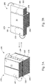
- FIG. 2B illustrates the chipset cooling assembly 210 in the open position, according to one or more embodiments of the disclosure.
- the cooling assembly 210 can be configured into the open position manually.
- the cooling assembly 210 can be configured into the open position automatically.
- the cooling assembly 210 can be equipped with a temperature sensor. The temperature sensor can detect whether the ambient temperature or the temperature of the chipset has exceeded a predetermined threshold. Upon exceeding the threshold temperature, the cooling assembly 210 can be actuated into the open position.
- the cooling assembly 210 can be connected to an administrator (not shown) over a wide-area-network (WAN) or a local-area-network (LAN). The administrator can actuate the cooling assembly 210 upon determining that the chipset has exceeded a threshold temperature.
- WAN wide-area-network
- LAN local-area-network
- a side surface of the first heat-dissipating dynamic feature 221 rotates inward to contact a portion of the side surface of the heat-dissipating static feature 220.
- any heat generated from the chipset (not shown) can travel through the heat-absorbing base 216 into the heat-dissipating static feature 220, and further into the first heat-dissipating dynamic feature 221 at the mating surfaces.
- the side surface of the second heat-dissipating dynamic feature 222 contacts a portion of the side surface of the heat-dissipating static feature 220.
- any heat generated from the chipset can travel through the heat-absorbing base 216 into the heat-dissipating static feature 220 and further into the second heat-dissipating dynamic feature 222 at the mating surfaces.
- the top surface of the heat-dissipating body 218 is now increased by rotating the first and second heat-dissipating dynamic features 221 and 222 outward.
- the cooling assembly 210 can be configured into the open position within the server device 500.
- the top surface T2 (in FIG. 2B ) of the cooling assembly 210 in the opened position is twice the size of the top surface T1 (in FIG. 2A ) of the cooling assembly in the closed position.
- the top surface T2 of the cooling assembly 210 equals to the width of the heat-dissipating static feature 220, squared, plus the top surfaces of the first and second heat-dissipating dynamic features 221 and 222.
- the heat drawn from the chipset A can be sent through the heat-absorbing base 216 into the heat-dissipating body 218, and out through the first and second heat-dissipating dynamic features 221 and 222.
- Fan modules F can be mounted adjacent to the cooling assembly 210 such that the fans direct forced air over the top surface T2 of the cooling assembly 210. The increased surface area improves the efficiency of the cooling assembly 210 as the forced air directed from the fan modules F has more surface space to contact the cooling assembly 210.
- FIG. 3A illustrates a cooling assembly 310 in a closed position according to one or more embodiments of the disclosure.
- the cooling assembly 310 can include a heat-absorbing base 316 and a heat-dissipating body 318.
- the cooling assembly 310 can be made of aluminum, copper metal, alloys, composite materials, heat pipes, or vapor chambers, for example.
- the cooling assembly 310 can be made from multiple materials.
- the cooling assembly 310 can include thermosiphons that interconnect the components of the heat-dissipating body 318. This is discussed in greater detail below with respect to FIGS. 3B and 3C .
- Other heat-conducting materials can also be implemented herein. Similar to the cooling assembly 210 of FIG. 2 , the shape of the heat-dissipating body 318 can be modified to create more surface area to increase the air-flow paths and improve the efficiency of the cooling assembly 310.
- the heat-dissipating body 318 can include a heat-dissipating static feature 320, a first heat-dissipating dynamic feature 321, and a second heat-dissipating dynamic feature 322.
- the top surface T1 of the cooling assembly 310 in the closed position is limited to the dimension of the first and second heat-dissipating dynamic features 321 and 322 stacked upon the heat-dissipating static feature 320. In other words, the top surface T1 of the cooling assembly 310 equals to the width of the heat-dissipating static feature 320, squared.
- the bottom surface of the first heat-dissipating dynamic feature 321 contacts a portion of the top surface of the heat-dissipating static feature 320.
- any heat generated from the chipset (not shown) can travel through the heat-absorbing base 316 into the heat-dissipating static feature 320 and further into the first heat-dissipating dynamic feature 321.
- the bottom surface of the second heat-dissipating dynamic feature 322 contacts a portion of the top surface of the heat-dissipating static feature 320.
- any heat generated from the chipset can travel through the heat-absorbing base 316 into the heat-dissipating static feature 320 and further into the second heat-dissipating dynamic feature 322. While the heat-dissipating body 318 provides the surface area of a cube, the cooling assembly 310 can be positioned to an open position where the number of surface areas are increased to improve the efficiency of the cooling assembly 310 (cite).
- FIG. 3B illustrates the chipset cooling assembly 310 in the open position, according to one or more embodiments of the disclosure.
- the first heat-dissipating dynamic feature 321 can be connected to the heat-dissipating static feature 320 at a first set of thermosiphons 323.
- the first set of thermosiphons 323 can be mechanical feature that functions as both a heat exchanger and a hinge.
- the first set of thermosiphons 323 can circulate fluid between first heat-dissipating dynamic feature 321 and the heat-dissipating static feature 320.
- the first set of thermosiphons 323 can expand, causing the first heat-dissipating dynamic feature 321 to rotate about the heat-dissipating static feature 320.
- the first set of thermosiphons 323 can be heat pipes, which circulates a fluid without the necessity of a mechanical pump.
- the first set of thermosiphons 323 can be made of a single heat-conducting material similar to the heat-dissipating body 318.
- the first set of thermosiphons 323 can be actuated by a motor.
- the second heat-dissipating dynamic feature 322 can be connected to the heat-dissipating static feature 320 at a second set of thermosiphons 324.
- the second set of thermosiphons 324 can be a mechanical feature that functions as both a heat exchanger and a hinge.
- the second set of thermosiphons 324 can circulate fluid between second heat-dissipating dynamic feature 322 and the heat-dissipating static feature 320. When the fluid reaches a certain temperature, the second set of thermosiphons 324 can expand, causing the second heat-dissipating dynamic feature 322 to rotate about the heat-dissipating static feature 320.
- the second set of thermosiphons 324 can be heat pipes, which circulates a fluid without the necessity of a mechanical pump.
- the second set of thermosiphons 324 can be made of a single heat-conducting material similar to the heat-dissipating body 318. Referring momentarily to FIG. 3C , the second set of thermosiphons 324 can be connected directly into the second heat-dissipating dynamic feature 322.
- the second set of thermosiphons 324 can be made from the same materials as the second heat-dissipating dynamic feature 322, the heat-dissipating static feature 320, or both components.
- the second set of thermosiphons 324 can be actuated by a motor.
- the thermosiphons 323 and 324 can be made up of a flexible metal conduit.
- a side surface of the first heat-dissipating dynamic feature 321 rotates inward to contact a portion of the side surface of the heat-dissipating static feature 320.
- any heat generated from the chipset (not shown) can travel through the heat-absorbing base 316 into the heat-dissipating static feature 320, and further into the first heat-dissipating dynamic feature 321.
- the side surface of the second heat-dissipating dynamic feature 322 contacts a portion of the side surface of the heat-dissipating static feature 320.
- any heat generated from the chipset can travel through the heat-absorbing base 316 into the heat-dissipating static feature 320 and further into the second heat-dissipating dynamic feature 322. Moreover, the top surface of the heat-dissipating body 318 is now increased by the rotating the first and second heat-dissipating dynamic features 321 and 322 outward. It should be understood that embodiments of the disclosure may only include a single heat-dissipating dynamic feature, or more than two heat-dissipating dynamic features.
- first and second heat-dissipating dynamic features 321 and 322 can be extended vertically from the heat-dissipating static feature 320.
- first and second heat-dissipating dynamic features 321 and 322 can be configured to move in multiple directions about the heat-dissipating static feature 320. It should be understood that the first and second heat-dissipating dynamic features 321 and 322 can be rotated, slid, or extended from the heat-dissipating static feature 320 in other directions and by other mechanisms to increase the surface area of the cooling assembly 310.
- the top surface T2 of the cooling assembly 310 in the opened position is twice the size of the top surface T1 (in FIG. 3A ) of the cooling assembly 310 in the closed position.
- the top surface T2 of the cooling assembly 310 equals to the width of the heat-dissipating static feature 320, squared, plus the top surfaces of both the first and second heat-dissipating dynamic features 321 and 322.
- the increased surface area improves the efficiency of the cooling assembly 310.
- the cooling assembly 310 incorporates rectangular first and second heat-dissipating dynamic features 321 and 322, other geometrically-shaped components can be incorporated.
- FIG. 4A illustrates a chipset cooling assembly 410 according to one or more embodiments of the disclosure.
- the cooling assembly 410 can include a heat-absorbing base 416 and a heat-dissipating body 418.
- the cooling assembly 410 can be made of aluminum, copper metal, alloys, composite materials, heat pipes, or vapor chambers, for example. Other heat-conducting materials can also be implemented herein.
- the shape of the heat-dissipating body 418 can be modified to create more surface area to increase the air-flow paths and improve the efficiency of the cooling assembly 410.
- the heat-dissipating body 418 can include a heat-dissipating static feature 420, a first heat-dissipating dynamic feature 421, and a second heat-dissipating dynamic feature 422.
- the first heat-dissipating dynamic feature 421 can be connected to the heat-dissipating static feature 420 at a first hinge 423.
- the second heat-dissipating dynamic feature 422 can be connected to the heat-dissipating static feature 420 at a second hinge 424.
- the surface area of the first heat-dissipating dynamic feature 421 is larger than the surface area of the second heat-dissipating dynamic feature 422.
- the first heat-dissipating dynamic feature 421 has a u-shape, configured to secure the inverted shape of the second heat-dissipating dynamic feature 422. While the first heat-dissipating dynamic feature 421 has a squared-u-shape, other shapes can be considered. For example, the first heat-dissipating dynamic feature 421 has a semi-circle u-shape, configured to secure an inverted semi-circle u-shape of the second heat-dissipating dynamic feature 422. In this configuration, the cooling assembly 410 provides more surface areas for airflow to make contact when in the open position. Other geometrical orientations can also be incorporated herein.
- FIG. 4A exemplifies the cooling assembly 410 in the closed position
- FIG. 4B illustrates the cooling assembly 410 in the open position.
- the top surface T1 (in FIG. 4A ) of the cooling assembly 410 in the closed position is limited to the dimension of the first and second heat-dissipating dynamic features 421 and 422 stacked upon the heat-dissipating static feature 420.
- the top surface T1 of the cooling assembly 410 equals to the width of the heat-dissipating static feature 420, squared.
- the bottom surface of the first heat-dissipating dynamic feature 421 contacts a portion of the top surface of the heat-dissipating static feature 420. In this way, any heat generated from the chipset (not shown) can travel through the heat-absorbing base 416 into the heat-dissipating static feature 420 and further into the first heat-dissipating dynamic feature 421. Furthermore, in the closed position, the bottom surface of the second heat-dissipating dynamic feature 422 contacts a portion of the top surface of the heat-dissipating static feature 420.
- any heat generated from the chipset can travel through the heat-absorbing base 416 into the heat-dissipating static feature 420 and further into the second heat-dissipating dynamic feature 422. While the heat-dissipating body 418 provides the surface areas of a cube, the first and second heat-dissipating dynamic features 421 and 422 can be positioned to an open position. In this position, the number of surface areas are increased to improve the efficiency of the cooling assembly 410.
- FIG. 4B illustrates the chipset cooling assembly 410 in the open position, according to one or more embodiments of the disclosure.
- a side surface of the first heat-dissipating dynamic feature 421 rotates inward to contacts a portion of the side surface of the heat-dissipating static feature 420.
- any heat generated from the chipset can travel through the heat-absorbing base 416 into the heat-dissipating static feature 420 and further into the first heat-dissipating dynamic feature 421 at the mating surfaces.
- the side surface of the second heat-dissipating dynamic feature 422 contacts a portion of the side surface of the heat-dissipating static feature 420.
- any heat generated from the chipset (not shown) can travel through the heat-absorbing base 416 into the heat-dissipating static feature 420 and further into the second heat-dissipating dynamic feature 422 at the mating surfaces.
- the top surface of the heat-dissipating body 418 is now increased by the rotating the first and second heat-dissipating dynamic features 421 and 422 outward.
- the top surface T2 of the cooling assembly 410 in the opened position is twice the size of the top surface T1 of the cooling assembly 410 (in FIG. 4A ) in the closed position.
- the top surface T2 of the cooling assembly 410 equals to the width of the heat-dissipating static feature 420 squared plus the top surfaces of the first and second heat-dissipating dynamic features 421 and 422.
- the cooling assembly 410 provides more surface areas along the side for airflow to make contact when in the open position. The increased surface area improves the efficiency of the cooling assembly 410.
Landscapes
- Engineering & Computer Science (AREA)
- Microelectronics & Electronic Packaging (AREA)
- Physics & Mathematics (AREA)
- Thermal Sciences (AREA)
- Computer Hardware Design (AREA)
- General Engineering & Computer Science (AREA)
- Cooling Or The Like Of Electrical Apparatus (AREA)
- Cooling Or The Like Of Semiconductors Or Solid State Devices (AREA)
Abstract
Description
- The present invention relates to apparatuses for dissipating heat that emanates from individual electronic units within a server device.
- The rapid increase in data storage and high bandwidth communication driven by Internet expansion is increasing the need for dense interconnection systems in data centers. These data centers are typically composed of rows of racks of servers. These servers need to be in high-bandwidth communication with other servers in the data centers. The high-bandwidth communication can be supported by either shielded electrical cables or increasingly active optical cables. Active optical cables support longer transmission distances and higher transmission bandwidths. An active optical cable typically has an optical engine incorporated into a transceiver on at least one end of the cable. The optical engine transforms electrical signals into optical signals (transmission [Tx] function), and transforms optical signals into electrical signals (receiver [Rx] function). An electronics rack can have hundreds or even thousands of interconnections, each of which generating heat that must be removed from the electronics rack. The inability to remove this heat can result in accelerated aging and/or premature failure of the interconnection of other components in the electronics rack. Therefore, there is a need to provide a cooling system in high speed communication devices that facilitates high-heat removal and dense packaging of the interconnections.
- Embodiments of the disclosure concern an apparatus for cooling an electronic component. The apparatus includes a heat-absorbing base configured to contact the electronic component within a server device and a heat-dissipating body connected to the heat-absorbing base. The heat-dissipating body includes a heat-dissipating static feature and at least one heat-dissipating dynamic feature. The at least one heat-dissipating dynamic feature is configured to be repositioned about the heat-dissipating static feature to increase a surface cooling area of the heat-dissipating body.
- In some embodiments of the disclosure, the heat-dissipating static feature and the heat-dissipating dynamic feature includes a highly thermal conductivity material that is selected from a group of aluminum, copper metal, alloys, or composite materials.
- In some embodiments of the disclosure, the heat-dissipating dynamic feature is configured to rotate about the heat-dissipating static feature via a first hinge device that connects the heat-dissipating dynamic feature with the heat-dissipating static feature and supports to transfer heat. In some embodiments of the disclosure, the rotation of the heat-dissipating dynamic feature about the heat-dissipating static feature creates an interlocking mating feature between the heat-dissipating dynamic feature and the heat-dissipating static feature.
- The apparatus can also include a second heat-dissipating dynamic feature configured to be repositioned about the heat-dissipating static feature to increase a surface cooling area of the heat-dissipating body. In some embodiments of the disclosure, the second heat-dissipating dynamic feature is configured to rotate about the heat-dissipating static feature via a second hinge device that connects the second heat-dissipating dynamic feature with the heat-dissipating static feature and supports to transfer heat.
- In some embodiments of the disclosure, the rotation of the second heat-dissipating dynamic feature about the heat-dissipating static feature creates an interlocking mating feature between the second heat-dissipating dynamic feature and the heat-dissipating static feature. In some embodiments of the disclosure, the second heat-dissipating dynamic feature is configured to rotate about the heat-dissipating static feature via a set of thermosiphons that connect the second heat-dissipating dynamic feature with the heat-dissipating static feature. In some embodiments of the disclosure, the set of thermosiphons includes a heat container that circulates a fluid.
- In some embodiments of the disclosure, the heat-dissipating dynamic feature and the second heat-dissipating dynamic feature include a rectangular shape. It should be noted that the heat-dissipating dynamic feature can include or geometrical shapes based on the product housed within the apparatus.
- In some embodiments of the disclosure, the heat-dissipating dynamic feature includes an interlocking feature, and the second heat-dissipating dynamic feature includes a corresponding interlocking feature configured to receive the interlocking feature of the heat-dissipating dynamic feature.
- In some embodiments of the disclosure, the heat-dissipating dynamic feature is configured to rotate about the heat-dissipating static feature via a second set of thermosiphons that connects the heat-dissipating dynamic feature with the heat-dissipating static feature. In some embodiments of the disclosure, the second set of thermosiphons includes a heat container that circulates a fluid.
- Embodiments of the disclosure concern a server device having an inlet side, an outlet side, a first sidewall, and a second sidewall, where the first sidewall and the second sidewall extend from the inlet side to the outlet side. The server device includes a fan module configured to draw airflow in from the inlet side and out to the outlet side, and a chipset configured to receive a cooling assembly. The cooling assembly includes a heat-absorbing base configured to contact the chipset and a heat-dissipating body connected to the heat-absorbing base. The heat-dissipating body includes a heat-dissipating static feature, a first heat-dissipating dynamic feature, and a second heat-dissipating dynamic feature. The first heat-dissipating dynamic feature and the second heat-dissipating dynamic feature are configured to rotate about the heat-dissipating static feature to increase a surface area of the heat-dissipating body.
- Additional features and advantages of the disclosure will be set forth in the description that follows, and in part, will be obvious from the description; or can be learned by practice of the principles disclosed herein. The features and advantages of the disclosure can be realized and obtained by means of the instruments and combinations particularly pointed out in the appended claims. These and other features of the disclosure will become fully apparent from the following description and appended claims, or can be learned by the practice of the principles set forth herein.
- In order to describe the manner in which the above-recited disclosure and its advantages and features can be obtained, a more particular description of the principles described above will be rendered by reference to specific examples illustrated in the appended drawings. These drawings depict only example aspects of the disclosure, and are therefore not to be considered as limiting of its scope. These principles are described and explained with additional specificity and detail through the use of the following drawings.
-
FIG. 1 is a perspective view of a conventional heatsink for cooling a chipset; -
FIG. 2A illustrates a cooling assembly in a closed position, according to one or more embodiments of the disclosure; -
FIG. 2B illustrates a cooling assembly in an opened position, according to one or more embodiments of the disclosure; -
FIG. 3A illustrates a cooling assembly in a closed position, according to one or more embodiments of the disclosure; -
FIG. 3B illustrates a cooling assembly in an opened position, according to one or more embodiments of the disclosure; -
FIG. 3C illustrates exemplary thermosiphon connectors implemented in the cooling assembly ofFIG. 3B , according to one or more embodiments of the disclosure; -
FIG. 4A illustrates a cooling assembly with different geometry in a closed position, according to one or more embodiments of the disclosure; -
FIG. 4B illustrates a cooling assembly with different geometry in an opened position, according to one or more embodiments of the disclosure; -
FIG. 5A shows a server device with a cooling assembly installed according to one or more embodiments of the disclosure; and -
FIG. 5B shows the server device ofFIG. 5A with a cooling assembly in an open position installed according to one or more embodiments of the disclosure. - The present invention is described with reference to the attached figures, where like reference numerals are used throughout the figures to designate similar or equivalent elements. The figures are not drawn to scale, and they are provided merely to illustrate the instant invention. Several aspects of the invention are described below with reference to example applications for illustration. It should be understood that numerous specific details, relationships, and methods are set forth to provide a full understanding of the invention. One having ordinary skill in the relevant art, however, will readily recognize that the invention can be practiced without one or more of the specific details, or with other methods. In other instances, well-known structures or operations are not shown in detail to avoid obscuring the invention. The present invention is not limited by the illustrated ordering of acts or events, as some acts may occur in different orders and/or concurrently with other acts or events. Furthermore, not all illustrated acts or events are required to implement a methodology in accordance with the present invention.
- In the high-performance computing industry, a typical server device can include one or more high-performance chipsets. For example, a computing server can include a computer-processing unit (CPU) or a graphics-processing unit (GPU). These chipsets can generate heat and/or have interconnections that generate heat. As indicated above, the inability to remove this heat can result in accelerated aging and/or premature failure of the chipset itself, or the interconnection of other components in the computing server. In typical computing servers, a heat sink exchanger can be attached directly on top of a high-performance chipset to try alleviate the heating issues discussed above.
-
FIG. 1 is a perspective view of aconventional heatsink 10 for cooling a chipset A. The chipset A can be mounted on a printed circuit board C. Theconventional heatsink 10 includes a heat-absorbingbase 16 and a heat-dissipatingfeature 18. The heat-absorbingbase 16 includes two installation features 14 at its corners. The installation features 14 enable the heat-absorbingbase 16 to be mounted to contact the top surface of the chipset A mounted on a printed circuit board C. For example, the installation features 14 includeapertures 20 configured to receive screws 22. The printed circuit board C can haveinstallation holes 24 configured to secure screws 22. As shown inFIG. 1 , twoinstallation holes 24 are formed near the chipset A. The heat-dissipatingfeature 18 can extend from the heat-absorbingbase 16 upward to transfer heat absorbed by the heat-absorbingbase 16 to the air. The heat-dissipatingfeature 18 includesheat dissipating fins 12. - In some embodiments, the printed circuit board C can have multiple chipsets A. The printed circuit board C can be located within a server device (not shown). As a result, the server device can include multiple chipsets A and accompanying
heatsinks 10. In typical server devices, fan modules are mounted adjacent to theheatsink 10 such that the fans direct forced air over theheatsink 10. Air preferably flows in one or more air-flow paths between theheat dissipating fins 12. Theheatsink 10 is traditionally made of aluminum, copper metal, heat pipes or vapor chambers. Theheatsink 10 can have a specific dimension that corresponds with the dimensions of the chipset A. Typically, a heatsink is designed to maximize its surface area in contact with the cooling medium surrounding it, such as airflow. The air velocity, choice of material, protrusion design, and surface treatment are factors that affect the performance of the heatsink. The surface area of theheatsink 10 is limited to that of the dissipatingfins 12. - As the demand for high-powered chipsets increases, the need for high-efficiency heatsinks increase as well. As indicated above, when performance demand increases the heat generated by the chipsets within the server device increases. Excessive temperatures can lead to premature failure and poor performance. Thus, the various embodiments disclosed herein provide a new heatsink design with increased surface areas, yet still maintain densely packaged high-performance chipsets. Specifically, the present disclosure teaches a cooling mechanism that includes a heat-absorbing base configured to contact the high-powered chipset and a heat-dissipating body connected to the heat-absorbing base. The heat-dissipating body includes a heat-dissipating static feature, a first heat-dissipating dynamic feature and a second heat-dissipating dynamic feature. The first heat-dissipating dynamic feature and the second heat-dissipating dynamic feature are configured to rotate about the heat-dissipating static feature to increase a surface area of the heat-dissipating body.
-
FIG. 2A illustrates acooling assembly 210 according to one or more embodiments of the disclosure. The coolingassembly 210 can include a heat-absorbingbase 216 and a heat-dissipatingbody 218. The coolingassembly 210 can be made of aluminum, copper metal, alloys, composite materials, heat pipes, or vapor chambers, for example. Other heat-conducting materials can also be implemented herein. The shape of the heat-dissipatingbody 218 can be modified to create more surface area to increase the air-flow paths and improve the efficiency of the coolingassembly 210. - Referring momentarily to
FIG. 5A , the coolingassembly 210 can be configured to contact a top surface of a chipset A. The chipset A can be printed on a circuit board C (inFIG. 1 ) within aserver device 500. The heat drawn from the chipset A can be sent through the heat-absorbingbase 216 into the heat-dissipatingbody 218. Fan modules F can be mounted adjacent to thecooling assembly 210 such that the fans direct forced air over the heat-dissipatingbody 218. - Referring back to
FIG. 2A , the heat-dissipatingbody 218 can include a heat-dissipatingstatic feature 220, a first heat-dissipatingdynamic feature 221, and a second heat-dissipatingdynamic feature 222. The first heat-dissipatingdynamic feature 221 can be connected to the heat-dissipatingstatic feature 220 at afirst hinge 223. Similarly, the second heat-dissipatingdynamic feature 222 can be connected to the heat-dissipatingstatic feature 220 at asecond hinge 224. While the coolingassembly 210 incorporateshinge assemblies dynamic features FIGS. 3A-3C . -
FIG. 2A exemplifies the coolingassembly 210 in the closed position. The top surface T1 of the coolingassembly 210 in the closed position is limited to the dimension of the first and second heat-dissipatingdynamic features static feature 220. In other words, the top surface T1 of the coolingassembly 210 is equal to the width of the heat-dissipatingstatic feature 220, squared. - In the closed position, the bottom surface of the first heat-dissipating
dynamic feature 221 contacts a portion of the top surface of the heat-dissipatingstatic feature 220. In this way, any heat generated from the chipset (not shown) can travel through the heat-absorbingbase 216 into the heat-dissipatingstatic feature 220, and further into the first heat-dissipatingdynamic feature 221 at the mating surfaces. Furthermore, in the closed position, the bottom surface of the second heat-dissipatingdynamic feature 222 contacts a portion of the top surface of the heat-dissipatingstatic feature 220. In this way, any heat generated from the chipset (not shown) can travel through the heat-absorbingbase 216 into the heat-dissipatingstatic feature 220, and further into the second heat-dissipatingdynamic feature 222 at the mating surfaces. While the heat-dissipatingbody 218 provides the surface areas of a cube, the first and second heat-dissipatingdynamic features assembly 210. - In some embodiments, the mating surfaces can be two flat surfaces between the heat-dissipating
static feature 220 and the first heat-dissipatingdynamic feature 221. In alternative embodiments, the mating surfaces can be two interlocking surfaces between the heat-dissipatingstatic feature 220 and the first heat-dissipatingdynamic feature 221. Similarly, the mating surfaces can be two flat surfaces between the heat-dissipatingstatic feature 220 and the second heat-dissipatingdynamic feature 222. In alternative embodiments, the mating surfaces can be two interlocking surfaces between the heat-dissipatingstatic feature 220 and the second heat-dissipatingdynamic feature 222. With interlocking surfaces, the surface area between the two mating pieces can be increased, improving the efficiency of the coolingassembly 210. The interlocking surfaces can include interlocking teeth. - The mating surfaces can also include a separate conducting material from the heat-dissipating
static feature 220 and the first heat-dissipatingdynamic feature 221. In some embodiments, the mating surfaces can include the same material as the heat-dissipatingstatic feature 220 and the first heat-dissipatingdynamic feature 221. Similarly, the mating surfaces can also include a separate conducting material from the heat-dissipatingstatic feature 220 and the second heat-dissipatingdynamic feature 222. In some embodiments, the mating surfaces can include the same material as the heat-dissipatingstatic feature 220 and the second heat-dissipatingdynamic feature 222. -
FIG. 2B illustrates thechipset cooling assembly 210 in the open position, according to one or more embodiments of the disclosure. In some embodiments, the coolingassembly 210 can be configured into the open position manually. In alternative embodiments, the coolingassembly 210 can be configured into the open position automatically. For example, the coolingassembly 210 can be equipped with a temperature sensor. The temperature sensor can detect whether the ambient temperature or the temperature of the chipset has exceeded a predetermined threshold. Upon exceeding the threshold temperature, the coolingassembly 210 can be actuated into the open position. Furthermore, the coolingassembly 210 can be connected to an administrator (not shown) over a wide-area-network (WAN) or a local-area-network (LAN). The administrator can actuate thecooling assembly 210 upon determining that the chipset has exceeded a threshold temperature. Other manual or automatic implementations can be incorporated herein. - In the opened position, a side surface of the first heat-dissipating
dynamic feature 221 rotates inward to contact a portion of the side surface of the heat-dissipatingstatic feature 220. In this way, any heat generated from the chipset (not shown) can travel through the heat-absorbingbase 216 into the heat-dissipatingstatic feature 220, and further into the first heat-dissipatingdynamic feature 221 at the mating surfaces. Similarly, in the open position, the side surface of the second heat-dissipatingdynamic feature 222 contacts a portion of the side surface of the heat-dissipatingstatic feature 220. In this way, any heat generated from the chipset (not shown) can travel through the heat-absorbingbase 216 into the heat-dissipatingstatic feature 220 and further into the second heat-dissipatingdynamic feature 222 at the mating surfaces. Moreover, the top surface of the heat-dissipatingbody 218 is now increased by rotating the first and second heat-dissipatingdynamic features - Referring momentarily to
FIG. 5B , the coolingassembly 210 can be configured into the open position within theserver device 500. The top surface T2 (inFIG. 2B ) of the coolingassembly 210 in the opened position is twice the size of the top surface T1 (inFIG. 2A ) of the cooling assembly in the closed position. Specifically, the top surface T2 of the coolingassembly 210 equals to the width of the heat-dissipatingstatic feature 220, squared, plus the top surfaces of the first and second heat-dissipatingdynamic features base 216 into the heat-dissipatingbody 218, and out through the first and second heat-dissipatingdynamic features cooling assembly 210 such that the fans direct forced air over the top surface T2 of the coolingassembly 210. The increased surface area improves the efficiency of the coolingassembly 210 as the forced air directed from the fan modules F has more surface space to contact the coolingassembly 210. -
FIG. 3A illustrates acooling assembly 310 in a closed position according to one or more embodiments of the disclosure. The coolingassembly 310 can include a heat-absorbingbase 316 and a heat-dissipatingbody 318. The coolingassembly 310 can be made of aluminum, copper metal, alloys, composite materials, heat pipes, or vapor chambers, for example. In some embodiments, the coolingassembly 310 can be made from multiple materials. For example, the coolingassembly 310 can include thermosiphons that interconnect the components of the heat-dissipatingbody 318. This is discussed in greater detail below with respect toFIGS. 3B and 3C . Other heat-conducting materials can also be implemented herein. Similar to thecooling assembly 210 ofFIG. 2 , the shape of the heat-dissipatingbody 318 can be modified to create more surface area to increase the air-flow paths and improve the efficiency of the coolingassembly 310. - The heat-dissipating
body 318 can include a heat-dissipatingstatic feature 320, a first heat-dissipatingdynamic feature 321, and a second heat-dissipatingdynamic feature 322. The top surface T1 of the coolingassembly 310 in the closed position is limited to the dimension of the first and second heat-dissipatingdynamic features static feature 320. In other words, the top surface T1 of the coolingassembly 310 equals to the width of the heat-dissipatingstatic feature 320, squared. In the closed position, the bottom surface of the first heat-dissipatingdynamic feature 321 contacts a portion of the top surface of the heat-dissipatingstatic feature 320. In this way, any heat generated from the chipset (not shown) can travel through the heat-absorbingbase 316 into the heat-dissipatingstatic feature 320 and further into the first heat-dissipatingdynamic feature 321. Furthermore, in the closed position, the bottom surface of the second heat-dissipatingdynamic feature 322 contacts a portion of the top surface of the heat-dissipatingstatic feature 320. In this way, any heat generated from the chipset (not shown) can travel through the heat-absorbingbase 316 into the heat-dissipatingstatic feature 320 and further into the second heat-dissipatingdynamic feature 322. While the heat-dissipatingbody 318 provides the surface area of a cube, the coolingassembly 310 can be positioned to an open position where the number of surface areas are increased to improve the efficiency of the cooling assembly 310 (cite). -
FIG. 3B illustrates thechipset cooling assembly 310 in the open position, according to one or more embodiments of the disclosure. The first heat-dissipatingdynamic feature 321 can be connected to the heat-dissipatingstatic feature 320 at a first set ofthermosiphons 323. The first set ofthermosiphons 323 can be mechanical feature that functions as both a heat exchanger and a hinge. For example, the first set ofthermosiphons 323 can circulate fluid between first heat-dissipatingdynamic feature 321 and the heat-dissipatingstatic feature 320. When the fluid reaches a certain temperature, the first set ofthermosiphons 323 can expand, causing the first heat-dissipatingdynamic feature 321 to rotate about the heat-dissipatingstatic feature 320. The first set ofthermosiphons 323 can be heat pipes, which circulates a fluid without the necessity of a mechanical pump. Alternatively, the first set ofthermosiphons 323 can be made of a single heat-conducting material similar to the heat-dissipatingbody 318. In some embodiments, the first set ofthermosiphons 323 can be actuated by a motor. - Similarly, the second heat-dissipating
dynamic feature 322 can be connected to the heat-dissipatingstatic feature 320 at a second set ofthermosiphons 324. The second set ofthermosiphons 324 can be a mechanical feature that functions as both a heat exchanger and a hinge. For example, the second set ofthermosiphons 324 can circulate fluid between second heat-dissipatingdynamic feature 322 and the heat-dissipatingstatic feature 320. When the fluid reaches a certain temperature, the second set ofthermosiphons 324 can expand, causing the second heat-dissipatingdynamic feature 322 to rotate about the heat-dissipatingstatic feature 320. The second set ofthermosiphons 324 can be heat pipes, which circulates a fluid without the necessity of a mechanical pump. Alternatively, the second set ofthermosiphons 324 can be made of a single heat-conducting material similar to the heat-dissipatingbody 318. Referring momentarily toFIG. 3C , the second set ofthermosiphons 324 can be connected directly into the second heat-dissipatingdynamic feature 322. The second set ofthermosiphons 324 can be made from the same materials as the second heat-dissipatingdynamic feature 322, the heat-dissipatingstatic feature 320, or both components. In some embodiments, the second set ofthermosiphons 324 can be actuated by a motor. Thethermosiphons - Referring back to
FIG. 3B , in the opened position, a side surface of the first heat-dissipatingdynamic feature 321 rotates inward to contact a portion of the side surface of the heat-dissipatingstatic feature 320. In this way, any heat generated from the chipset (not shown) can travel through the heat-absorbingbase 316 into the heat-dissipatingstatic feature 320, and further into the first heat-dissipatingdynamic feature 321. Similarly, in the opened position, the side surface of the second heat-dissipatingdynamic feature 322 contacts a portion of the side surface of the heat-dissipatingstatic feature 320. In this way, any heat generated from the chipset (not shown) can travel through the heat-absorbingbase 316 into the heat-dissipatingstatic feature 320 and further into the second heat-dissipatingdynamic feature 322. Moreover, the top surface of the heat-dissipatingbody 318 is now increased by the rotating the first and second heat-dissipatingdynamic features - In alternative embodiments, the first and second heat-dissipating
dynamic features static feature 320. In some embodiments, the first and second heat-dissipatingdynamic features static feature 320. It should be understood that the first and second heat-dissipatingdynamic features static feature 320 in other directions and by other mechanisms to increase the surface area of the coolingassembly 310. - The top surface T2 of the cooling
assembly 310 in the opened position is twice the size of the top surface T1 (inFIG. 3A ) of the coolingassembly 310 in the closed position. Specifically, the top surface T2 of the coolingassembly 310 equals to the width of the heat-dissipatingstatic feature 320, squared, plus the top surfaces of both the first and second heat-dissipatingdynamic features assembly 310. While the coolingassembly 310 incorporates rectangular first and second heat-dissipatingdynamic features -
FIG. 4A illustrates achipset cooling assembly 410 according to one or more embodiments of the disclosure. The coolingassembly 410 can include a heat-absorbingbase 416 and a heat-dissipatingbody 418. The coolingassembly 410 can be made of aluminum, copper metal, alloys, composite materials, heat pipes, or vapor chambers, for example. Other heat-conducting materials can also be implemented herein. The shape of the heat-dissipatingbody 418 can be modified to create more surface area to increase the air-flow paths and improve the efficiency of the coolingassembly 410. - The heat-dissipating
body 418 can include a heat-dissipatingstatic feature 420, a first heat-dissipatingdynamic feature 421, and a second heat-dissipatingdynamic feature 422. The first heat-dissipatingdynamic feature 421 can be connected to the heat-dissipatingstatic feature 420 at afirst hinge 423. Similarly, the second heat-dissipatingdynamic feature 422 can be connected to the heat-dissipatingstatic feature 420 at asecond hinge 424. Noticeably, the surface area of the first heat-dissipatingdynamic feature 421 is larger than the surface area of the second heat-dissipatingdynamic feature 422. The first heat-dissipatingdynamic feature 421 has a u-shape, configured to secure the inverted shape of the second heat-dissipatingdynamic feature 422. While the first heat-dissipatingdynamic feature 421 has a squared-u-shape, other shapes can be considered. For example, the first heat-dissipatingdynamic feature 421 has a semi-circle u-shape, configured to secure an inverted semi-circle u-shape of the second heat-dissipatingdynamic feature 422. In this configuration, the coolingassembly 410 provides more surface areas for airflow to make contact when in the open position. Other geometrical orientations can also be incorporated herein. - While
FIG. 4A exemplifies the coolingassembly 410 in the closed position,FIG. 4B illustrates the coolingassembly 410 in the open position. The top surface T1 (inFIG. 4A ) of the coolingassembly 410 in the closed position is limited to the dimension of the first and second heat-dissipatingdynamic features static feature 420. In other words, the top surface T1 of the coolingassembly 410 equals to the width of the heat-dissipatingstatic feature 420, squared. - In the closed position, the bottom surface of the first heat-dissipating
dynamic feature 421 contacts a portion of the top surface of the heat-dissipatingstatic feature 420. In this way, any heat generated from the chipset (not shown) can travel through the heat-absorbingbase 416 into the heat-dissipatingstatic feature 420 and further into the first heat-dissipatingdynamic feature 421. Furthermore, in the closed position, the bottom surface of the second heat-dissipatingdynamic feature 422 contacts a portion of the top surface of the heat-dissipatingstatic feature 420. In this way, any heat generated from the chipset (not shown) can travel through the heat-absorbingbase 416 into the heat-dissipatingstatic feature 420 and further into the second heat-dissipatingdynamic feature 422. While the heat-dissipatingbody 418 provides the surface areas of a cube, the first and second heat-dissipatingdynamic features assembly 410. -
FIG. 4B illustrates thechipset cooling assembly 410 in the open position, according to one or more embodiments of the disclosure. In the opened position, a side surface of the first heat-dissipatingdynamic feature 421 rotates inward to contacts a portion of the side surface of the heat-dissipatingstatic feature 420. In this way, any heat generated from the chipset (not shown) can travel through the heat-absorbingbase 416 into the heat-dissipatingstatic feature 420 and further into the first heat-dissipatingdynamic feature 421 at the mating surfaces. Similarly, in the opened position, the side surface of the second heat-dissipatingdynamic feature 422 contacts a portion of the side surface of the heat-dissipatingstatic feature 420. In this way, any heat generated from the chipset (not shown) can travel through the heat-absorbingbase 416 into the heat-dissipatingstatic feature 420 and further into the second heat-dissipatingdynamic feature 422 at the mating surfaces. Moreover, the top surface of the heat-dissipatingbody 418 is now increased by the rotating the first and second heat-dissipatingdynamic features - The top surface T2 of the cooling
assembly 410 in the opened position is twice the size of the top surface T1 of the cooling assembly 410 (inFIG. 4A ) in the closed position. Specifically, the top surface T2 of the coolingassembly 410 equals to the width of the heat-dissipatingstatic feature 420 squared plus the top surfaces of the first and second heat-dissipatingdynamic features dynamic feature 421 has a u-shape and the second heat-dissipatingdynamic feature 422 has an inverted u-shape, the coolingassembly 410 provides more surface areas along the side for airflow to make contact when in the open position. The increased surface area improves the efficiency of the coolingassembly 410. - The terminology used herein is for the purpose of describing particular embodiments only and is not intended to limit the invention. As used herein, the singular forms "a," "an," and "the" are intended to include the plural forms as well, unless the context clearly indicates otherwise. Furthermore, to the extent that the terms "including," "includes," "having," "has," "with," or variants thereof are used in either the detailed description and/or the claims, such terms are intended to be inclusive in a manner similar to the term "comprising."
- Unless otherwise defined, all terms (including technical and scientific terms) used herein have the same meaning as commonly understood by one of ordinary skill in the art to which this invention belongs. Furthermore, terms, such as those defined in commonly used dictionaries, should be interpreted as having a meaning that is consistent with their meaning in the context of the relevant art, and will not be interpreted in an idealized or overly formal sense unless expressly so defined herein.
Claims (14)
- An apparatus (210, 310, 410) for cooling an electronic component, characterized by comprising:a heat-absorbing base (216, 316, 416); anda heat-dissipating body (218, 318, 418) connected to the heat-absorbing base (216, 316, 416), wherein the heat-dissipating body (218, 318, 418) comprises a heat-dissipating static feature (220, 320, 420) and a first heat-dissipating dynamic feature (221, 321, 421),wherein the first heat-dissipating dynamic feature (221, 321, 421) is configured to be repositioned about the heat-dissipating static feature (220, 320, 420) to increase a surface cooling area of the heat-dissipating body (218, 318, 418).
- The apparatus of claim 1, characterized in that the heat-dissipating static feature (220, 320, 420) and the first heat-dissipating dynamic feature (221, 321, 421) comprises a highly thermal conductivity material is selected from a group of aluminum, copper metal, alloys, or composite materials.
- The apparatus of claim 1 or 2, characterized in that the first heat-dissipating dynamic feature (321) is configured to rotate about the heat-dissipating static feature (320) via a first set of thermosiphons (323) that connects the first heat-dissipating dynamic feature (321) with the heat-dissipating static feature (320).
- The apparatus of claim 3, characterized in that the first set of thermosiphons (323) comprises a heat container that circulates a fluid.
- The apparatus of claim 1 or 2, characterized in that the first heat-dissipating dynamic feature (221) is configured to rotate about the heat-dissipating static feature (220) via a first hinge device (223) that connects the first heat-dissipating dynamic feature (221) with the heat-dissipating static feature (220) and supports heat transfer to the first heat-dissipating dynamic feature (221).
- The apparatus of claim 5, characterized in that the rotation of the first heat-dissipating dynamic feature (221) about the heat-dissipating static feature (220) creates an interlocking mating feature between the first heat-dissipating dynamic feature (221) and the heat-dissipating static feature (220).
- The apparatus of any of claims 1-5, characterized in that the heat-dissipating body (218, 318, 418) further comprises a second heat-dissipating dynamic feature (222, 322, 422) configured to be repositioned about the heat-dissipating static feature (220, 320, 420) to increase the surface cooling area of the heat-dissipating body (218, 318, 418).
- The apparatus of claim 7, characterized in that the second heat-dissipating dynamic feature (222) is configured to rotate about the heat-dissipating static feature (220) via a second hinge device (224) that connects the second heat-dissipating dynamic feature (222) with the heat-dissipating static feature (220) and supports heat transfer to the second heat-dissipating dynamic feature (222).
- The apparatus of claim 8, characterized in that the rotation of the second heat-dissipating dynamic feature (222) about the heat-dissipating static feature (220) creates an interlocking mating feature between the second heat-dissipating dynamic feature (222) and the heat-dissipating static feature (220).
- The apparatus of claim 7, characterized in that the second heat-dissipating dynamic feature (322) is configured to rotate about the heat-dissipating static feature (320) via a second set of thermosiphons (324) that connects the second heat-dissipating dynamic feature (322) with the heat-dissipating static feature (320).
- The apparatus of claim 10, characterized in that the second set of thermosiphons (322) comprises a heat pipe that circulates a fluid.
- The apparatus of any of claims 7-11, characterized in that the first heat-dissipating dynamic feature (221) and the second heat-dissipating dynamic feature (222) comprise a rectangular shape.
- The apparatus of any of claims 7-11, characterized in that the first heat-dissipating dynamic feature (421) comprises an interlocking feature and the second heat-dissipating dynamic feature (422) comprises a corresponding interlocking feature configured to receive the interlocking feature of the first heat-dissipating dynamic feature (421).
- A server device (500) having an inlet side, an outlet side, a first sidewall, and a second sidewall, where the first sidewall and the second sidewall extend from the inlet side to the outlet side, the server device characterized by comprising:a fan module (F) configured to draw airflow in from the inlet side to the outlet side; anda chipset (A); andthe apparatus (210) of any preceding claim, wherein the heat-absorbing base (216) is configured to contact the chipset (A).
Applications Claiming Priority (2)
| Application Number | Priority Date | Filing Date | Title |
|---|---|---|---|
| US201862676075P | 2018-05-24 | 2018-05-24 | |
| US16/114,962 US10779439B2 (en) | 2018-05-24 | 2018-08-28 | Remote heat exchanger |
Publications (2)
| Publication Number | Publication Date |
|---|---|
| EP3573438A1 true EP3573438A1 (en) | 2019-11-27 |
| EP3573438B1 EP3573438B1 (en) | 2021-07-07 |
Family
ID=65529269
Family Applications (1)
| Application Number | Title | Priority Date | Filing Date |
|---|---|---|---|
| EP19157947.3A Active EP3573438B1 (en) | 2018-05-24 | 2019-02-19 | Remote heat exchanger |
Country Status (5)
| Country | Link |
|---|---|
| US (1) | US10779439B2 (en) |
| EP (1) | EP3573438B1 (en) |
| JP (1) | JP6952071B2 (en) |
| CN (1) | CN110536585A (en) |
| TW (1) | TWI673468B (en) |
Cited By (1)
| Publication number | Priority date | Publication date | Assignee | Title |
|---|---|---|---|---|
| US20210345519A1 (en) * | 2020-06-29 | 2021-11-04 | Intel Corporation | Technologies for reconfigurable heat sinks |
Families Citing this family (9)
| Publication number | Priority date | Publication date | Assignee | Title |
|---|---|---|---|---|
| DE112019001566B4 (en) * | 2018-03-27 | 2022-04-28 | Mitsubishi Electric Corporation | Cooling device, cooling device provided with cover, housing with cooling device and inverter |
| US10939536B1 (en) * | 2019-09-16 | 2021-03-02 | Ciena Corporation | Secondary side heatsink techniques for optical and electrical modules |
| US11703921B2 (en) * | 2020-03-09 | 2023-07-18 | Nvidia Corporation | Configurable heatsink |
| US11582888B2 (en) * | 2021-03-25 | 2023-02-14 | Baidu Usa Llc | Hybrid cooling device for acceleration hardware |
| WO2023048723A1 (en) * | 2021-09-24 | 2023-03-30 | Intel Corporation | Hybrid cooler to thermally cool semiconductor devices inside and outside a chip package |
| CN117666043B (en) * | 2022-08-31 | 2025-12-12 | 锐捷网络股份有限公司 | A heat dissipation architecture for an optoelectronic module and an electronic device |
| CN117082845B (en) * | 2023-10-17 | 2024-01-30 | 湖南省康普通信技术有限责任公司 | Modularized data center heat dissipation cold channel device |
| CN119472956B (en) * | 2025-01-17 | 2025-06-03 | 苏州海特自动化设备有限公司 | Industrial computer cooling unit |
| CN120891904B (en) * | 2025-09-30 | 2026-01-30 | 苏州海特自动化设备有限公司 | Industrial computer heat dissipation assembly and industrial computer |
Citations (5)
| Publication number | Priority date | Publication date | Assignee | Title |
|---|---|---|---|---|
| WO2001041520A1 (en) * | 1999-12-06 | 2001-06-07 | Cool Shield, Inc. | U-shaped heat sink assembly |
| WO2003088022A1 (en) * | 2002-04-06 | 2003-10-23 | Zalman Tech Co., Ltd | Chipset cooling device of video graphic adapter card |
| CN1707395A (en) * | 2004-06-09 | 2005-12-14 | 中国科学院计算技术研究所 | Radiating system for four-path frame server |
| US20060023423A1 (en) * | 2004-07-30 | 2006-02-02 | Via Technologies, Inc. | Expandable heat sink |
| US20080302509A1 (en) * | 2007-06-08 | 2008-12-11 | Ama Precision Inc. | Heat sink and modular heat sink |
Family Cites Families (24)
| Publication number | Priority date | Publication date | Assignee | Title |
|---|---|---|---|---|
| JPH01171040U (en) | 1988-05-23 | 1989-12-04 | ||
| JPH04125455U (en) | 1991-04-26 | 1992-11-16 | 正博 森田 | heat sink |
| JPH0677363A (en) * | 1992-08-24 | 1994-03-18 | Fujitsu Ltd | Expandable radiation fin |
| US5329436A (en) | 1993-10-04 | 1994-07-12 | David Chiu | Removable heat sink for xenon arc lamp packages |
| US5486982A (en) * | 1994-06-10 | 1996-01-23 | Hsu; Winston | Modular electronic packaging for computer servers |
| US6137683A (en) * | 1999-10-01 | 2000-10-24 | Compal Electronics, Inc. | Heat-dissipating device for an electronic component |
| CN100361045C (en) * | 2005-07-08 | 2008-01-09 | 华硕电脑股份有限公司 | Stretching type heat dissipation device |
| JP4967307B2 (en) | 2005-10-24 | 2012-07-04 | セイコーエプソン株式会社 | projector |
| JP4675224B2 (en) | 2005-12-08 | 2011-04-20 | シャープ株式会社 | Air conditioner |
| US7298619B1 (en) * | 2006-05-02 | 2007-11-20 | Hewlett-Packard Development Company, L.P. | Cable management arm with integrated heat exchanger |
| US20080130221A1 (en) * | 2006-12-02 | 2008-06-05 | Krishnakumar Varadarajan | Thermal hinge for lid cooling |
| TWI398617B (en) | 2009-06-11 | 2013-06-11 | Hon Hai Prec Ind Co Ltd | Heat sink |
| CN201535493U (en) | 2009-07-22 | 2010-07-28 | 杜姬芳 | LED heat dissipation device |
| CN201575736U (en) | 2009-11-17 | 2010-09-08 | 董林洲 | Independent multi-cavity flat plate type heat conduction device |
| TWI425347B (en) * | 2009-11-19 | 2014-02-01 | 仁寶電腦工業股份有限公司 | Thermal module for electronic devices |
| JP2011181731A (en) * | 2010-03-02 | 2011-09-15 | Molex Inc | Electronic apparatus with socket for card type component |
| TW201314425A (en) | 2011-09-30 | 2013-04-01 | 鴻海精密工業股份有限公司 | Heat sink and electronic device using the same |
| CN203232979U (en) | 2013-05-13 | 2013-10-09 | 黄雅莉 | Connector with heat sink |
| CN105474766A (en) * | 2013-07-22 | 2016-04-06 | 惠普发展公司,有限责任合伙企业 | Heat sink |
| CN203554868U (en) | 2013-10-17 | 2014-04-16 | 南宁市博泰华五金模具厂 | A heat radiating fin |
| US9668334B2 (en) * | 2014-05-23 | 2017-05-30 | General Electric Company | Thermal clamp apparatus for electronic systems |
| CN206557699U (en) | 2017-03-24 | 2017-10-13 | 湖南兴天电子科技有限公司 | High efficiency and heat radiation server |
| US10595439B2 (en) * | 2018-06-25 | 2020-03-17 | Intel Corporation | Movable heatsink utilizing flexible heat pipes |
| US11231757B2 (en) * | 2018-08-01 | 2022-01-25 | Intel Corporation | Thermal dissipation in dual-chassis devices |
-
2018
- 2018-08-28 US US16/114,962 patent/US10779439B2/en active Active
-
2019
- 2019-01-17 TW TW108101874A patent/TWI673468B/en active
- 2019-01-31 CN CN201910098168.3A patent/CN110536585A/en active Pending
- 2019-02-19 EP EP19157947.3A patent/EP3573438B1/en active Active
- 2019-03-27 JP JP2019060134A patent/JP6952071B2/en active Active
Patent Citations (5)
| Publication number | Priority date | Publication date | Assignee | Title |
|---|---|---|---|---|
| WO2001041520A1 (en) * | 1999-12-06 | 2001-06-07 | Cool Shield, Inc. | U-shaped heat sink assembly |
| WO2003088022A1 (en) * | 2002-04-06 | 2003-10-23 | Zalman Tech Co., Ltd | Chipset cooling device of video graphic adapter card |
| CN1707395A (en) * | 2004-06-09 | 2005-12-14 | 中国科学院计算技术研究所 | Radiating system for four-path frame server |
| US20060023423A1 (en) * | 2004-07-30 | 2006-02-02 | Via Technologies, Inc. | Expandable heat sink |
| US20080302509A1 (en) * | 2007-06-08 | 2008-12-11 | Ama Precision Inc. | Heat sink and modular heat sink |
Cited By (1)
| Publication number | Priority date | Publication date | Assignee | Title |
|---|---|---|---|---|
| US20210345519A1 (en) * | 2020-06-29 | 2021-11-04 | Intel Corporation | Technologies for reconfigurable heat sinks |
Also Published As
| Publication number | Publication date |
|---|---|
| EP3573438B1 (en) | 2021-07-07 |
| US10779439B2 (en) | 2020-09-15 |
| US20190364697A1 (en) | 2019-11-28 |
| CN110536585A (en) | 2019-12-03 |
| JP6952071B2 (en) | 2021-10-20 |
| TW202004115A (en) | 2020-01-16 |
| TWI673468B (en) | 2019-10-01 |
| JP2019204498A (en) | 2019-11-28 |
Similar Documents
| Publication | Publication Date | Title |
|---|---|---|
| EP3573438B1 (en) | Remote heat exchanger | |
| US7400505B2 (en) | Hybrid cooling system and method for a multi-component electronics system | |
| US7961475B2 (en) | Apparatus and method for facilitating immersion-cooling of an electronic subsystem | |
| US7408776B2 (en) | Conductive heat transport cooling system and method for a multi-component electronics system | |
| US5844777A (en) | Apparatus for heat removal from a PC card array | |
| US8164901B2 (en) | High efficiency heat removal system for rack mounted computer equipment | |
| US8422218B2 (en) | Liquid cooled condensers for loop heat pipe like enclosure cooling | |
| US8369091B2 (en) | Interleaved, immersion-cooling apparatus and method for an electronic subsystem of an electronics rack | |
| US8276394B2 (en) | Modular absorption heat sink devices for passive cooling of servers and other electronics | |
| US10368464B2 (en) | Thermal solution for transceiver module | |
| US20080259566A1 (en) | Efficiently cool data centers and electronic enclosures using loop heat pipes | |
| US10136559B2 (en) | Liquid-assisted air cooling of electronic racks with modular fan and heat exchangers | |
| US5289694A (en) | Circuit card mounting assembly | |
| US6906922B2 (en) | Integrated heat-dissipating module | |
| US8111516B2 (en) | Housing used as heat collector | |
| US9036351B2 (en) | Passive cooling system and method for electronics devices | |
| US12464684B2 (en) | Directing coolant to flow toward heat sinks of electric components in immersion cooling systems | |
| KR101011084B1 (en) | Endothermic members, cooling devices and electronic devices | |
| US20210112654A1 (en) | Thermal management systems having signal transfer routing for use with electronic devices | |
| KR20010063385A (en) | Apparatus for cooling the printed board assembly | |
| JPH1013068A (en) | Heat sink mounting structure |
Legal Events
| Date | Code | Title | Description |
|---|---|---|---|
| PUAI | Public reference made under article 153(3) epc to a published international application that has entered the european phase |
Free format text: ORIGINAL CODE: 0009012 |
|
| STAA | Information on the status of an ep patent application or granted ep patent |
Free format text: STATUS: THE APPLICATION HAS BEEN PUBLISHED |
|
| AK | Designated contracting states |
Kind code of ref document: A1 Designated state(s): AL AT BE BG CH CY CZ DE DK EE ES FI FR GB GR HR HU IE IS IT LI LT LU LV MC MK MT NL NO PL PT RO RS SE SI SK SM TR |
|
| AX | Request for extension of the european patent |
Extension state: BA ME |
|
| STAA | Information on the status of an ep patent application or granted ep patent |
Free format text: STATUS: REQUEST FOR EXAMINATION WAS MADE |
|
| 17P | Request for examination filed |
Effective date: 20200224 |
|
| RBV | Designated contracting states (corrected) |
Designated state(s): AL AT BE BG CH CY CZ DE DK EE ES FI FR GB GR HR HU IE IS IT LI LT LU LV MC MK MT NL NO PL PT RO RS SE SI SK SM TR |
|
| STAA | Information on the status of an ep patent application or granted ep patent |
Free format text: STATUS: EXAMINATION IS IN PROGRESS |
|
| 17Q | First examination report despatched |
Effective date: 20200630 |
|
| GRAP | Despatch of communication of intention to grant a patent |
Free format text: ORIGINAL CODE: EPIDOSNIGR1 |
|
| STAA | Information on the status of an ep patent application or granted ep patent |
Free format text: STATUS: GRANT OF PATENT IS INTENDED |
|
| INTG | Intention to grant announced |
Effective date: 20210218 |
|
| GRAS | Grant fee paid |
Free format text: ORIGINAL CODE: EPIDOSNIGR3 |
|
| GRAA | (expected) grant |
Free format text: ORIGINAL CODE: 0009210 |
|
| STAA | Information on the status of an ep patent application or granted ep patent |
Free format text: STATUS: THE PATENT HAS BEEN GRANTED |
|
| AK | Designated contracting states |
Kind code of ref document: B1 Designated state(s): AL AT BE BG CH CY CZ DE DK EE ES FI FR GB GR HR HU IE IS IT LI LT LU LV MC MK MT NL NO PL PT RO RS SE SI SK SM TR |
|
| REG | Reference to a national code |
Ref country code: GB Ref legal event code: FG4D |
|
| REG | Reference to a national code |
Ref country code: AT Ref legal event code: REF Ref document number: 1409914 Country of ref document: AT Kind code of ref document: T Effective date: 20210715 |
|
| REG | Reference to a national code |
Ref country code: DE Ref legal event code: R096 Ref document number: 602019005807 Country of ref document: DE |
|
| REG | Reference to a national code |
Ref country code: IE Ref legal event code: FG4D |
|
| REG | Reference to a national code |
Ref country code: LT Ref legal event code: MG9D |
|
| REG | Reference to a national code |
Ref country code: NL Ref legal event code: MP Effective date: 20210707 |
|
| REG | Reference to a national code |
Ref country code: AT Ref legal event code: MK05 Ref document number: 1409914 Country of ref document: AT Kind code of ref document: T Effective date: 20210707 |
|
| PG25 | Lapsed in a contracting state [announced via postgrant information from national office to epo] |
Ref country code: ES Free format text: LAPSE BECAUSE OF FAILURE TO SUBMIT A TRANSLATION OF THE DESCRIPTION OR TO PAY THE FEE WITHIN THE PRESCRIBED TIME-LIMIT Effective date: 20210707 Ref country code: FI Free format text: LAPSE BECAUSE OF FAILURE TO SUBMIT A TRANSLATION OF THE DESCRIPTION OR TO PAY THE FEE WITHIN THE PRESCRIBED TIME-LIMIT Effective date: 20210707 Ref country code: SE Free format text: LAPSE BECAUSE OF FAILURE TO SUBMIT A TRANSLATION OF THE DESCRIPTION OR TO PAY THE FEE WITHIN THE PRESCRIBED TIME-LIMIT Effective date: 20210707 Ref country code: RS Free format text: LAPSE BECAUSE OF FAILURE TO SUBMIT A TRANSLATION OF THE DESCRIPTION OR TO PAY THE FEE WITHIN THE PRESCRIBED TIME-LIMIT Effective date: 20210707 Ref country code: LT Free format text: LAPSE BECAUSE OF FAILURE TO SUBMIT A TRANSLATION OF THE DESCRIPTION OR TO PAY THE FEE WITHIN THE PRESCRIBED TIME-LIMIT Effective date: 20210707 Ref country code: AT Free format text: LAPSE BECAUSE OF FAILURE TO SUBMIT A TRANSLATION OF THE DESCRIPTION OR TO PAY THE FEE WITHIN THE PRESCRIBED TIME-LIMIT Effective date: 20210707 Ref country code: BG Free format text: LAPSE BECAUSE OF FAILURE TO SUBMIT A TRANSLATION OF THE DESCRIPTION OR TO PAY THE FEE WITHIN THE PRESCRIBED TIME-LIMIT Effective date: 20211007 Ref country code: HR Free format text: LAPSE BECAUSE OF FAILURE TO SUBMIT A TRANSLATION OF THE DESCRIPTION OR TO PAY THE FEE WITHIN THE PRESCRIBED TIME-LIMIT Effective date: 20210707 Ref country code: NO Free format text: LAPSE BECAUSE OF FAILURE TO SUBMIT A TRANSLATION OF THE DESCRIPTION OR TO PAY THE FEE WITHIN THE PRESCRIBED TIME-LIMIT Effective date: 20211007 Ref country code: PT Free format text: LAPSE BECAUSE OF FAILURE TO SUBMIT A TRANSLATION OF THE DESCRIPTION OR TO PAY THE FEE WITHIN THE PRESCRIBED TIME-LIMIT Effective date: 20211108 Ref country code: NL Free format text: LAPSE BECAUSE OF FAILURE TO SUBMIT A TRANSLATION OF THE DESCRIPTION OR TO PAY THE FEE WITHIN THE PRESCRIBED TIME-LIMIT Effective date: 20210707 |
|
| PG25 | Lapsed in a contracting state [announced via postgrant information from national office to epo] |
Ref country code: PL Free format text: LAPSE BECAUSE OF FAILURE TO SUBMIT A TRANSLATION OF THE DESCRIPTION OR TO PAY THE FEE WITHIN THE PRESCRIBED TIME-LIMIT Effective date: 20210707 Ref country code: LV Free format text: LAPSE BECAUSE OF FAILURE TO SUBMIT A TRANSLATION OF THE DESCRIPTION OR TO PAY THE FEE WITHIN THE PRESCRIBED TIME-LIMIT Effective date: 20210707 Ref country code: GR Free format text: LAPSE BECAUSE OF FAILURE TO SUBMIT A TRANSLATION OF THE DESCRIPTION OR TO PAY THE FEE WITHIN THE PRESCRIBED TIME-LIMIT Effective date: 20211008 |
|
| REG | Reference to a national code |
Ref country code: DE Ref legal event code: R097 Ref document number: 602019005807 Country of ref document: DE |
|
| PG25 | Lapsed in a contracting state [announced via postgrant information from national office to epo] |
Ref country code: DK Free format text: LAPSE BECAUSE OF FAILURE TO SUBMIT A TRANSLATION OF THE DESCRIPTION OR TO PAY THE FEE WITHIN THE PRESCRIBED TIME-LIMIT Effective date: 20210707 |
|
| PLBE | No opposition filed within time limit |
Free format text: ORIGINAL CODE: 0009261 |
|
| STAA | Information on the status of an ep patent application or granted ep patent |
Free format text: STATUS: NO OPPOSITION FILED WITHIN TIME LIMIT |
|
| PG25 | Lapsed in a contracting state [announced via postgrant information from national office to epo] |
Ref country code: SM Free format text: LAPSE BECAUSE OF FAILURE TO SUBMIT A TRANSLATION OF THE DESCRIPTION OR TO PAY THE FEE WITHIN THE PRESCRIBED TIME-LIMIT Effective date: 20210707 Ref country code: SK Free format text: LAPSE BECAUSE OF FAILURE TO SUBMIT A TRANSLATION OF THE DESCRIPTION OR TO PAY THE FEE WITHIN THE PRESCRIBED TIME-LIMIT Effective date: 20210707 Ref country code: RO Free format text: LAPSE BECAUSE OF FAILURE TO SUBMIT A TRANSLATION OF THE DESCRIPTION OR TO PAY THE FEE WITHIN THE PRESCRIBED TIME-LIMIT Effective date: 20210707 Ref country code: EE Free format text: LAPSE BECAUSE OF FAILURE TO SUBMIT A TRANSLATION OF THE DESCRIPTION OR TO PAY THE FEE WITHIN THE PRESCRIBED TIME-LIMIT Effective date: 20210707 Ref country code: CZ Free format text: LAPSE BECAUSE OF FAILURE TO SUBMIT A TRANSLATION OF THE DESCRIPTION OR TO PAY THE FEE WITHIN THE PRESCRIBED TIME-LIMIT Effective date: 20210707 Ref country code: AL Free format text: LAPSE BECAUSE OF FAILURE TO SUBMIT A TRANSLATION OF THE DESCRIPTION OR TO PAY THE FEE WITHIN THE PRESCRIBED TIME-LIMIT Effective date: 20210707 |
|
| 26N | No opposition filed |
Effective date: 20220408 |
|
| PG25 | Lapsed in a contracting state [announced via postgrant information from national office to epo] |
Ref country code: IT Free format text: LAPSE BECAUSE OF FAILURE TO SUBMIT A TRANSLATION OF THE DESCRIPTION OR TO PAY THE FEE WITHIN THE PRESCRIBED TIME-LIMIT Effective date: 20210707 |
|
| PG25 | Lapsed in a contracting state [announced via postgrant information from national office to epo] |
Ref country code: MC Free format text: LAPSE BECAUSE OF FAILURE TO SUBMIT A TRANSLATION OF THE DESCRIPTION OR TO PAY THE FEE WITHIN THE PRESCRIBED TIME-LIMIT Effective date: 20210707 |
|
| REG | Reference to a national code |
Ref country code: CH Ref legal event code: PL |
|
| REG | Reference to a national code |
Ref country code: BE Ref legal event code: MM Effective date: 20220228 |
|
| PG25 | Lapsed in a contracting state [announced via postgrant information from national office to epo] |
Ref country code: LU Free format text: LAPSE BECAUSE OF NON-PAYMENT OF DUE FEES Effective date: 20220219 |
|
| PG25 | Lapsed in a contracting state [announced via postgrant information from national office to epo] |
Ref country code: LI Free format text: LAPSE BECAUSE OF NON-PAYMENT OF DUE FEES Effective date: 20220228 Ref country code: IE Free format text: LAPSE BECAUSE OF NON-PAYMENT OF DUE FEES Effective date: 20220219 Ref country code: CH Free format text: LAPSE BECAUSE OF NON-PAYMENT OF DUE FEES Effective date: 20220228 |
|
| PG25 | Lapsed in a contracting state [announced via postgrant information from national office to epo] |
Ref country code: BE Free format text: LAPSE BECAUSE OF NON-PAYMENT OF DUE FEES Effective date: 20220228 |
|
| PG25 | Lapsed in a contracting state [announced via postgrant information from national office to epo] |
Ref country code: MK Free format text: LAPSE BECAUSE OF FAILURE TO SUBMIT A TRANSLATION OF THE DESCRIPTION OR TO PAY THE FEE WITHIN THE PRESCRIBED TIME-LIMIT Effective date: 20210707 Ref country code: CY Free format text: LAPSE BECAUSE OF FAILURE TO SUBMIT A TRANSLATION OF THE DESCRIPTION OR TO PAY THE FEE WITHIN THE PRESCRIBED TIME-LIMIT Effective date: 20210707 |
|
| PG25 | Lapsed in a contracting state [announced via postgrant information from national office to epo] |
Ref country code: HU Free format text: LAPSE BECAUSE OF FAILURE TO SUBMIT A TRANSLATION OF THE DESCRIPTION OR TO PAY THE FEE WITHIN THE PRESCRIBED TIME-LIMIT; INVALID AB INITIO Effective date: 20190219 |
|
| PG25 | Lapsed in a contracting state [announced via postgrant information from national office to epo] |
Ref country code: MT Free format text: LAPSE BECAUSE OF FAILURE TO SUBMIT A TRANSLATION OF THE DESCRIPTION OR TO PAY THE FEE WITHIN THE PRESCRIBED TIME-LIMIT Effective date: 20210707 |
|
| PG25 | Lapsed in a contracting state [announced via postgrant information from national office to epo] |
Ref country code: TR Free format text: LAPSE BECAUSE OF FAILURE TO SUBMIT A TRANSLATION OF THE DESCRIPTION OR TO PAY THE FEE WITHIN THE PRESCRIBED TIME-LIMIT Effective date: 20210707 |
|
| PGFP | Annual fee paid to national office [announced via postgrant information from national office to epo] |
Ref country code: FR Payment date: 20251222 Year of fee payment: 8 |
|
| PGFP | Annual fee paid to national office [announced via postgrant information from national office to epo] |
Ref country code: GB Payment date: 20260106 Year of fee payment: 8 |
|
| PGFP | Annual fee paid to national office [announced via postgrant information from national office to epo] |
Ref country code: DE Payment date: 20251224 Year of fee payment: 8 |