EP3573274B1 - Kommunikationsverfahren und netzwerkvorrichtung - Google Patents
Kommunikationsverfahren und netzwerkvorrichtung Download PDFInfo
- Publication number
- EP3573274B1 EP3573274B1 EP18744960.8A EP18744960A EP3573274B1 EP 3573274 B1 EP3573274 B1 EP 3573274B1 EP 18744960 A EP18744960 A EP 18744960A EP 3573274 B1 EP3573274 B1 EP 3573274B1
- Authority
- EP
- European Patent Office
- Prior art keywords
- resource
- network device
- dmrs ports
- dmrs
- terminal device
- Prior art date
- Legal status (The legal status is an assumption and is not a legal conclusion. Google has not performed a legal analysis and makes no representation as to the accuracy of the status listed.)
- Active
Links
- 238000004891 communication Methods 0.000 title claims description 73
- 238000000034 method Methods 0.000 title claims description 55
- 238000004590 computer program Methods 0.000 claims description 5
- 230000011664 signaling Effects 0.000 description 36
- 238000010586 diagram Methods 0.000 description 33
- 230000005540 biological transmission Effects 0.000 description 32
- 230000006870 function Effects 0.000 description 9
- 238000001228 spectrum Methods 0.000 description 9
- 239000002699 waste material Substances 0.000 description 9
- 230000003993 interaction Effects 0.000 description 8
- 230000000694 effects Effects 0.000 description 4
- 238000005516 engineering process Methods 0.000 description 4
- 230000007774 longterm Effects 0.000 description 4
- 230000009286 beneficial effect Effects 0.000 description 2
- 238000010295 mobile communication Methods 0.000 description 2
- 238000003491 array Methods 0.000 description 1
- 230000001413 cellular effect Effects 0.000 description 1
- 238000013500 data storage Methods 0.000 description 1
- 230000001419 dependent effect Effects 0.000 description 1
- 238000005562 fading Methods 0.000 description 1
- 230000001788 irregular Effects 0.000 description 1
- 238000007726 management method Methods 0.000 description 1
- 230000003287 optical effect Effects 0.000 description 1
- 239000013307 optical fiber Substances 0.000 description 1
- 239000004065 semiconductor Substances 0.000 description 1
- 239000007787 solid Substances 0.000 description 1
Images


Classifications
-
- H—ELECTRICITY
- H04—ELECTRIC COMMUNICATION TECHNIQUE
- H04W—WIRELESS COMMUNICATION NETWORKS
- H04W28/00—Network traffic management; Network resource management
- H04W28/02—Traffic management, e.g. flow control or congestion control
- H04W28/0205—Traffic management, e.g. flow control or congestion control at the air interface
-
- H—ELECTRICITY
- H04—ELECTRIC COMMUNICATION TECHNIQUE
- H04L—TRANSMISSION OF DIGITAL INFORMATION, e.g. TELEGRAPHIC COMMUNICATION
- H04L5/00—Arrangements affording multiple use of the transmission path
- H04L5/003—Arrangements for allocating sub-channels of the transmission path
- H04L5/0048—Allocation of pilot signals, i.e. of signals known to the receiver
- H04L5/0051—Allocation of pilot signals, i.e. of signals known to the receiver of dedicated pilots, i.e. pilots destined for a single user or terminal
-
- H—ELECTRICITY
- H04—ELECTRIC COMMUNICATION TECHNIQUE
- H04L—TRANSMISSION OF DIGITAL INFORMATION, e.g. TELEGRAPHIC COMMUNICATION
- H04L5/00—Arrangements affording multiple use of the transmission path
- H04L5/02—Channels characterised by the type of signal
- H04L5/06—Channels characterised by the type of signal the signals being represented by different frequencies
- H04L5/10—Channels characterised by the type of signal the signals being represented by different frequencies with dynamo-electric generation of carriers; with mechanical filters or demodulators
-
- H—ELECTRICITY
- H04—ELECTRIC COMMUNICATION TECHNIQUE
- H04L—TRANSMISSION OF DIGITAL INFORMATION, e.g. TELEGRAPHIC COMMUNICATION
- H04L5/00—Arrangements affording multiple use of the transmission path
- H04L5/0001—Arrangements for dividing the transmission path
- H04L5/0014—Three-dimensional division
- H04L5/0016—Time-frequency-code
-
- H—ELECTRICITY
- H04—ELECTRIC COMMUNICATION TECHNIQUE
- H04L—TRANSMISSION OF DIGITAL INFORMATION, e.g. TELEGRAPHIC COMMUNICATION
- H04L5/00—Arrangements affording multiple use of the transmission path
- H04L5/003—Arrangements for allocating sub-channels of the transmission path
- H04L5/0037—Inter-user or inter-terminal allocation
-
- H—ELECTRICITY
- H04—ELECTRIC COMMUNICATION TECHNIQUE
- H04L—TRANSMISSION OF DIGITAL INFORMATION, e.g. TELEGRAPHIC COMMUNICATION
- H04L5/00—Arrangements affording multiple use of the transmission path
- H04L5/003—Arrangements for allocating sub-channels of the transmission path
- H04L5/0078—Timing of allocation
-
- H—ELECTRICITY
- H04—ELECTRIC COMMUNICATION TECHNIQUE
- H04L—TRANSMISSION OF DIGITAL INFORMATION, e.g. TELEGRAPHIC COMMUNICATION
- H04L5/00—Arrangements affording multiple use of the transmission path
- H04L5/0091—Signaling for the administration of the divided path
- H04L5/0094—Indication of how sub-channels of the path are allocated
-
- H—ELECTRICITY
- H04—ELECTRIC COMMUNICATION TECHNIQUE
- H04W—WIRELESS COMMUNICATION NETWORKS
- H04W28/00—Network traffic management; Network resource management
- H04W28/16—Central resource management; Negotiation of resources or communication parameters, e.g. negotiating bandwidth or QoS [Quality of Service]
-
- H—ELECTRICITY
- H04—ELECTRIC COMMUNICATION TECHNIQUE
- H04W—WIRELESS COMMUNICATION NETWORKS
- H04W72/00—Local resource management
- H04W72/04—Wireless resource allocation
- H04W72/044—Wireless resource allocation based on the type of the allocated resource
- H04W72/0446—Resources in time domain, e.g. slots or frames
-
- H—ELECTRICITY
- H04—ELECTRIC COMMUNICATION TECHNIQUE
- H04W—WIRELESS COMMUNICATION NETWORKS
- H04W72/00—Local resource management
- H04W72/20—Control channels or signalling for resource management
- H04W72/23—Control channels or signalling for resource management in the downlink direction of a wireless link, i.e. towards a terminal
-
- H—ELECTRICITY
- H04—ELECTRIC COMMUNICATION TECHNIQUE
- H04W—WIRELESS COMMUNICATION NETWORKS
- H04W72/00—Local resource management
- H04W72/50—Allocation or scheduling criteria for wireless resources
- H04W72/53—Allocation or scheduling criteria for wireless resources based on regulatory allocation policies
-
- H—ELECTRICITY
- H04—ELECTRIC COMMUNICATION TECHNIQUE
- H04W—WIRELESS COMMUNICATION NETWORKS
- H04W28/00—Network traffic management; Network resource management
- H04W28/02—Traffic management, e.g. flow control or congestion control
Definitions
- Embodiments of this application relate to the field of communications technologies, and in particular, to a communication method and a network device.
- a network device may be equipped with a plurality of antennas to implement spatial multiplexing transmission by using a multi-input multi-output (multi-input multi-output, MIMO) technology.
- MIMO multi-input multi-output
- a plurality of data streams are transmitted on one time-frequency resource, each data stream is transmitted on an independent spatial layer, and each spatial layer is mapped to a different antenna port for transmission.
- the network device needs to configure a demodulation reference signal (demodulation reference signal, DMRS) for each antenna port respectively and send the DMRS to the terminal device.
- the terminal device estimates a radio channel between the network device and the terminal device by using the received DMRS, to obtain channel state information, and then correctly obtains, by using the channel state information, information sent by the network device on a plurality of spatial layers.
- DMRS demodulation reference signal
- a time division multiplexing mode, a frequency division multiplexing mode, a code division multiplexing mode, and the like may be usually used between DMRSs corresponding to different antenna ports.
- a fixed time-frequency resource element (resource element, RE) is configured for each antenna port for DMRS transmission.
- RE resource element
- the network device may support transmission on a maximum of N spatial layers.
- the network device does not need to schedule all the N spatial layers in some time segments due to irregular distribution of services in the system. In this case, the network device needs to allocate a corresponding DMRS port to only a scheduled spatial layer.
- a code division multiplexing mode is mainly used between DMRSs. Power of an unused DMRS port is used for a scheduled DMRS port to enhance channel estimation performance. In a future new radio communications system, time division multiplexing or frequency division multiplexing is mainly used between DMRSs. If the prior-art solution is directly used, an RE corresponding to an unused DMRS port is neither used to send a DMRS nor used to send data information.
- a quantity of spatial layers scheduled by the network device is less than a maximum quantity of spatial layers that can be supported by the network device, one or more DMRS ports are not used, and REs corresponding to these DMRS ports are neither used to transmit a DMRS nor used to carry data information. This causes a waste of communication resources and reduces spectrum efficiency of a system.
- US 2014/0233466 A1 provides a method for communication in a wireless communications network.
- the method comprises: transmitting, by a network element in a first cell, a first DMRS on a first DMRS port; transmitting, by the network element, a first PDSCH on the first DMRS port; and transmitting, by the network, information indicating that the first DMRS port is used to transmit the first PDSCH, and information about a second DMRS port that is not used to transmit the first PDSCH but is used to transmit a second DMRS, wherein the first DMRS and the second DMRS are orthogonal to one another.
- This application provides a communication method and a network device, to resolve a problem of a waste of communication resources in a wireless communications system and low spectrum efficiency of the system.
- the network device determines that the resource corresponding to the at least one DMRS port of the plurality of DMRS ports of the network device is not used to transmit the DMRS in the first time segment; and determines the first resource used to carry the first data information to be sent to the terminal device, where the first resource includes the resource that is corresponding to the at least one DMRS port and that is not used to transmit the DMRS.
- the network device sends the indication information of the first resource to the terminal device.
- the terminal device determines, based on the received indication information of the first resource, the first resource used to carry the first data information in the first time segment; and receives, from the network device, the first data information carried on the first resource.
- the network device and the terminal device may transmit data information by using the idle resource. This avoids a waste of communication resources and improves spectrum efficiency.
- the network device determines that the resource corresponding to the at least one DMRS port of the plurality of DMRS ports of the network device is not used to transmit the DMRS in the first time segment; and determines the first resource used to carry the first data information, where the first resource includes the resource that is corresponding to the at least one DMRS port and that is not used to transmit the DMRS.
- the network device sends the indication information of the first resource to the terminal device.
- the terminal device determines, based on the received indication information of the first resource, the first resource used to carry the first data information; and finally sends the first data information to the network device by using the first resource to carry the first data information.
- the terminal device and the network device may implement uplink data information transmission by using the resource corresponding to the idle DMRS port of the network device. This improves spectrum efficiency.
- FIG. 1 is a schematic structural diagram of a communications system according to an embodiment of this application.
- the communications system may include at least one network device 110 and a plurality of terminal devices 120 located in a coverage area of the network device 110.
- FIG. 1 shows one network device and two terminal devices in an example.
- the communications system may include a plurality of network devices, and another quantity of terminal devices may be included in a coverage area of each network device. This is not limited in this embodiment of this application.
- the communication method provided in the embodiments of this application may be applied to information transmission between a network device and a terminal device in a communications system.
- the information transmission may be downlink transmission of information sent from the network device to the terminal device, or may be uplink transmission of information sent by the terminal device and received by the network device.
- a specific mode is determined according to an actual requirement, and is not limited herein.
- the communications system may further include other network entities such as a network controller and a mobility management entity. This is not limited in the embodiments of this application.
- the embodiments of this application may be applied to communications systems such as a Global System for Mobile Communications (Global System for Mobile Communications, GSM) system, a Code Division Multiple Access (Code Division Multiple Access, CDMA) system, a Wideband Code Division Multiple Access (Wideband Code Division Multiple Access, WCDMA) system, a General Packet Radio Service (General Packet Radio Service, GPRS) system, a Long Term Evolution (Long Term Evolution, LTE) system, an LTE frequency division duplexing (frequency division duplexing, FDD) system, an LTE time division duplexing (time division duplexing, TDD) system, a Universal Mobile Telecommunications System (Universal Mobile Telecommunications System, UMTS), and another wireless communications system that uses an orthogonal frequency division multiplexing (orthogonal frequency division multiplexing, OFDM) technology.
- GSM Global System for Mobile Communications
- CDMA Code Division Multiple Access
- WCDMA Wideband Code Division Multiple Access
- GPRS General Packet Radio Service
- LTE Long Term Evolution
- Network architectures and service scenarios that are described in the embodiments of this application are intended to describe the technical solutions in the embodiments of this application more clearly, but do not constitute a limitation on the technical solutions provided in the embodiments of this application.
- a person of ordinary skill in the art may learn that with evolution of the network architectures and emergence of new service scenarios, the technical solutions provided in the embodiments of this application are also applicable to resolve a similar technical problem.
- a network device in the embodiments of this application may be configured to provide a wireless communication function for a terminal device.
- the network device may include a macro base station, a micro base station (also referred to as a small cell), a relay node, an access point, and the like that are in various forms.
- the network device may be a base transceiver station (base transceiver station, BTS) in GSM or CDMA, may be a nodeB (nodeB, NB) in WCDMA, may be an evolved NodeB (evolved nodeB, eNB, or e-NodeB) in LTE, or may be a corresponding device gNB in a 5G network.
- BTS base transceiver station
- NB nodeB
- WCDMA nodeB
- eNB evolved NodeB
- e-NodeB evolved NodeB
- all the foregoing apparatuses that provide a wireless communication function for the terminal device are collectively referred to as a
- the terminal device is also referred to as user equipment (User Equipment, UE), a mobile station (mobile station, MS), a mobile terminal (mobile terminal), a terminal (terminal), or the like.
- the terminal device may communicate with one or more core networks through a radio access network (radio access network, RAN).
- RAN radio access network
- the terminal device may be a mobile phone (also referred to as a "cellular" phone) or a computer with a mobile terminal, or the like.
- the terminal device may be a portable, pocket-sized, handheld, computer built-in, or in-vehicle mobile apparatus that exchanges voice and/or data with the radio access network. This is not specifically limited in the embodiments of this application.
- a plurality of refers to two or more than two.
- the term “and/or” describes an association relationship between associated objects and indicates that three relationships may exist. For example, A and/or B may indicate the following three cases: Only A exists, both A and B exist, and only B exists.
- the character "/" usually represents an "or" relationship between the associated objects.
- a wireless communications system includes an existing Long Term Evolution/Long Term Evolution advanced communications system and a new radio (new radio, NR) system that is being developed.
- an orthogonal frequency division multiple access mode is usually used for a downlink multiple access mode.
- a main characteristic of the orthogonal frequency division multiple access mode is that: A transmission resource is divided into orthogonal REs, and a signal sent by a transmit end is carried on an RE to be transmitted to a receive end. Because different REs are orthogonal to each other, the receive end may separately receive a signal sent on each RE.
- the signal carried on the RE is distorted after being transmitted through the channel.
- the distortion is referred to as a channel coefficient.
- the receive end needs to estimate the channel coefficient.
- a pilot-based solution is usually used.
- a transmit end transmits a known signal on a specific RE; and a receive end estimates a channel coefficient based on a received signal and the known signal, performs interpolation on a channel coefficient on another RE based on the channel coefficient obtained through the estimation, and then receives and demodulates a data signal by using the estimated channel coefficient.
- the embodiments of this application are mainly intended for a future new radio communications system, and time division multiplexing or frequency division multiplexing is mainly used between DMRSs. If the prior-art solution is still directly used, an RE corresponding to an unused DMRS port is neither used to transmit a DMRS nor used to send data information, resulting in a waste of communication resources and low spectrum efficiency of the system.
- This application provides a communication method and a network device, to avoid a waste of communication resources and improves spectrum efficiency of a system.
- the network device needs to first determine a usage situation of a plurality of DMRS ports of the network device. Before determining the usage situation of the plurality of DMRS ports of the network device is described, a multiplexing mode of a DMRS antenna port in the communications system is briefly described first.
- FIG. 2 is a schematic diagram of a DMRS pattern of an antenna port in a communications system.
- a network device may be equipped with eight antennas to implement spatial multiplexing transmission by using a MIMO technology, that is, eight DMRS ports are defined in the communications system. Accordingly, the network device can support transmission on a maximum of eight spatial layers.
- a time division/frequency division multiplexing mode is used at a DMRS port.
- a horizontal direction represents a time domain
- a vertical direction represents a frequency domain
- each small block represents an RE
- RE locations corresponding to a DMRS port 1 and a DMRS port 2 represent transmission locations of DMRSs at an antenna port 1 and an antenna port 2
- the antenna port 1 and the antenna port 2 are multiplexed in an orthogonal code division manner.
- Distribution and multiplexing modes of a DMRS port 3 and a DMRS port 4, a DMRS port 5 and a DMRS port 6, and a DMRS port 7 and a DMRS port 8 are similar to those of the DMRS port 1 and the DMRS port 2. Details are not described herein.
- a time domain resource, a frequency domain resource, and a code domain resource of an RE that is corresponding to one antenna port and that is used to transmit a DMRS are referred to as a DMRS pattern of the antenna port.
- FIG. 3 is a schematic diagram of scheduling some DMRS ports by a network device according to the embodiment shown in FIG. 2 .
- eight DMRS ports are defined in a communications system, that is, the network device supports transmission on a maximum of eight spatial layers.
- the network device schedules only two spatial layers, and a DMRS port 1 and a DMRS port 2 are allocated to only the two spatial layers.
- the network device transmits information only on REs corresponding to the DMRS port 1 and the DMRS port 2, and REs corresponding to defined DMRS ports 3, 4, 5, 6, 7, and 8 are neither used to transmit a DMRS nor used to send data information.
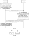
- FIG. 4 is a schematic interaction diagram of a communication method according to an embodiment of this application. As shown in FIG. 4 , this method may include the following steps.
- a network device determines that a resource corresponding to at least one DMRS port of a plurality of DMRS ports of the network device is not used to transmit a DMRS in a first time segment.
- the at least one DMRS port includes a first DMRS port.
- the network device when the network device needs to send information to a terminal device, the network device first determines the first time segment required for sending the information.
- the first time segment may be duration (duration) occupied by the network device for sending information.
- the first time segment may specifically be one or more subframes (subframe), may be one or more slots (slot), may be one or more mini-slots (mini-slot), or may be one or more symbols. This is not limited herein.
- the plurality of subframes/slots/mini-slots/symbols may be consecutive subframes/slots/mini-slots/symbols, or may be subframes/slots/mini-slots/symbols that are not completely consecutive. This is not limited herein.
- the network device determines that the resource corresponding to the at least one DMRS port of the plurality of DMRS ports of the network device is not used to transmit the DMRS in the first time segment. In other words, the network device does not schedule all spatial layers, and an unused resource corresponding to the at least one DMRS port exists.
- the at least one DMRS port to which the resource not used to transmit the DMRS is corresponding includes the first DMRS port, and the first DMRS port is one or more of the plurality of DMRS ports of the network device.
- a quantity of first DMRS ports is not limited herein.
- the network device determines a first resource used to carry, in the first time segment, first data information to be sent to the terminal device.
- the first resource includes a resource corresponding to the first DMRS port.
- the network device when the network device needs to send the first data information to the terminal device, the network device first determines a bearer used to transmit the first data information in the first time segment, that is, the first resource used to carry the first data information.
- the first data information in this embodiment is data information to be transmitted in the first time segment.
- the first resource determined by the network device includes the resource corresponding to the first DMRS port and a third resource other than the resource corresponding to the first DMRS port.
- the third resource is a resource that is predetermined by the network device and that is used to send a physical downlink shared channel (Physical Downlink Shared Channel, PDSCH) in the first time segment.
- PDSCH Physical Downlink Shared Channel
- the resource corresponding to the first DMRS port is used to carry data information.
- the resource corresponding to the first DMRS port can be used to carry only the data information.
- the resource may also be used to carry control information.
- the network device may use the resource corresponding to the first DMRS port and another unused resource to carry the first data information.
- resources that are determined by the network device and that may be used to carry the first data information in the first time segment are collectively referred to as the first resource.
- the network device sends indication information of the first resource to the terminal device.
- the network device sends the indication information of the first resource to the terminal device. So that the terminal device may determine, based on the indication information of the first resource, the first resource used to carry the first data information when the network device sends the first data information.
- the indication information of the first resource includes information used to indicate the resource corresponding to the first DMRS port. Because the resource corresponding to the first DMRS port is not used to transmit the DMRS in the first time segment, the resource corresponding to the first DMRS port is used to transmit the first data information.
- the information about the resource corresponding to the first DMRS port includes a port number of the first DMRS port.
- the terminal device may determine, based on the port number of the first DMRS port, the resource that is corresponding to the first DMRS port and that carries the first data information.
- the indication information of the resource corresponding to the first DMRS port may occupy a 2-bit field.
- a case in which the plurality of DMRS ports include two DMRS ports is used as an example, and a meaning of the 2-bit field indication information may be shown in Table 1.
- Table 1 shows a meaning of the indication information when the indication information of the first resource is the 2-bit field.
- a state 01 indicates a DMRS port 1.
- the terminal device may determine that a resource corresponding to the DMRS port 1 carries the first data information.
- a state 10 indicates a DMRS port 2.
- the terminal device may determine that a resource corresponding to the DMRS port 2 carries the first data information.
- a state 11 indicates the DMRS port 1 and the DMRS port 2.
- the terminal device may determine that the resources corresponding to the DMRS port 1 and the DMRS port 2 carry the first data information.
- the field may further include a reserved state indication, for example, a state 00 in Table 1. This state may be understood as not indicating any DMRS port.
- the terminal device determines that none of resources corresponding to all DMRS ports including the DMRS port 1 and the DMRS port 2 carries the first data information.
- the indication information of the resource corresponding to the first DMRS port is a 4-bit field.
- Table 2 shows an indication meaning of an i th bit when the indication information of the first resource is the 4-bit field.
- a state 0 indicates a reserved state or is understood as not indicating the DMRS port (2i-1) and the DMRS port 2i.
- the terminal device determines that resources corresponding to the DMRS port (2i-1) and the DMRS port 2i do not carry the first data information.
- a state 1 indicates the DMRS port (2i-1) and the DMRS port 2i.
- the terminal device determines that the resources corresponding to the DMRS port (2i-1) and the DMRS port 2i carry the first data information.
- a quantity of bits of the field included in the indication information of the resource corresponding to the first DMRS port may alternatively be another value except 2 and 4, and an indication meaning of each state of the field is not limited to that in Table 1 and Table 2.
- the quantity of bits of the field included in the indication information of the resource corresponding to the first DMRS port and the indication meaning of each state of the corresponding field may be determined according to an actual requirement. This is not limited in this embodiment.
- the information about the resource corresponding to the first DMRS port includes an index of the resource corresponding to the first DMRS port.
- the index may be understood as a number or a sequence number of the resource corresponding to the first DMRS port. This is not limited herein.
- the terminal device may determine, based on information about the index of the resource corresponding to the first DMRS port, the first resource carrying the first data information.
- indication information of the index of the resource corresponding to the first DMRS port may be a 2-bit field.
- a resource corresponding to a DMRS port 1 is a resource 1 (resource index 1)
- a resource corresponding to a DMRS port 2 is a resource 2.
- a meaning of the 2-bit field indication information may be shown in Table 3.
- Table 3 shows a meaning of the indication information when the indication information of the index is the 2-bit field.
- a state 01 indicates the resource 1.
- the terminal device may determine that the resource 1 carries the first data information.
- a state 10 indicates the resource 2.
- the terminal device may determine that the resource 2 carries the first data information.
- a state 11 indicates the resource 1 and the resource 2.
- the terminal device may determine that both the resource 1 and the resource 2 carry the first data information.
- the field may further include a reserved state indication, for example, a state 00 in Table 1. The state may be understood as not indicating any resource. In this case, the terminal device determines that neither of the resource 1 and the resource 2 carries the first data information.
- the indication information of the index of the resource corresponding to the first DMRS port is a 4-bit field.
- a meaning of the 4-bit field indication information which is not covered by the claimed invention may be shown in Table 4.
- a state 0 indicates a reserved state or is understood as not indicating the resource i. In this case, the terminal device determines that the resource i does not carry the first data information.
- a state 1 indicates the resource i. In this case, the terminal device determines that the resource i carries the first data information.
- the indication information of the first resource includes information used to indicate a resource corresponding to a second DMRS port other than the first DMRS port in the plurality of DMRS ports.
- the terminal device determines may that the resource corresponding to the second DMRS port other than the first DMRS port in the plurality of DMRSs does not carry the first data information, so as to indirectly determine the resource corresponding to the first DMRS port and determine the first resource carrying the first data information.
- the information about the resource corresponding to the second DMRS port other than the first DMRS port in the plurality of DMRS ports includes a port number of the second DMRS port.
- the terminal device may indirectly determine the port number of the first DMRS port based on the port number of the second DMRS port, and determine the resource corresponding to the first DMRS port, so as to determine the first resource carrying the first data information.
- the indication information of the resource corresponding to the second DMRS port is shown in Table 2.
- Table 1 is used as an example.
- the state 01 indicates the DMRS port 1.
- the terminal device may determine that the resource corresponding to the DMRS port 1 does not carry the first data information, and determine that the resource corresponding to the DMRS port 2 carries the first data information.
- the state 10 indicates the DMRS port 2.
- the terminal device may determine that the resource corresponding to the DMRS port 2 does not carry the first data information, and determine that the resource corresponding to the DMRS port 1 carries the first data information.
- the state 11 indicates the DMRS port 1 and the DMRS port 2.
- the terminal device may determine that the resources corresponding to the DMRS port 1 and the DMRS port 2 do not carry the first data information.
- the field may further include a reserved state indication, for example, the state 00 in Table 1. The state may be understood as not indicating any DMRS port. In this case, the terminal device determines that the resources corresponding to all the DMRS ports including the DMRS port 1 and the DMRS port 2 carry the first data information.
- the information of the resource corresponding to the second DMRS port other than the first DMRS port in the plurality of DMRS ports includes an index of the resource corresponding to the second DMRS port.
- the terminal device may determine, based on information about the index of the resource corresponding to the second DMRS port, a resource not carrying the first data information, so as to indirectly determine the first resource carrying the first data information.
- the indication information of the resource corresponding to the second DMRS port according to the claimed invention is shown in Table 2.
- Table 2 For an example for describing a specific meaning of the indication information of the resource corresponding to the second DMRS port, refer to the foregoing description of Table 1, Table 2, Table 3, or Table 4. Details are not described herein.
- the indication information of the first resource includes indication information of a third resource other than the resource corresponding to the first DMRS port in the first resource.
- the indication information of the first resource includes the information used to indicate the resource corresponding to the first DMRS port and includes the indication information of the third resource.
- the terminal device may determine, based on the information used to indicate the resource corresponding to the first DMRS port, resource of the first resource used to carry the first data information, and determine, based on the indication information of the third resource, resource of the first resource used to transmit the DMRS, so as to receive the DMRS and the first data information that the network device uses the first resource to carry.
- the indication information of the third resource includes information used to indicate an index of a symbol included in the third resource.
- the third resource includes seven symbols in a slot, where first and second symbols are used to carry control information, a third symbol is used to transmit a DMRS, and fourth to seventh symbols are used to transmit data information.
- the terminal device determines, based on the information about the index, indicated in the indication information of the third resource, of the symbol included in the third resource, a symbol carrying the data information, and further receives, from the corresponding symbol, the data information transmitted by the network device.
- the third resource may alternatively include one or more symbols in the seven symbols, and the plurality of symbols may be consecutive symbols or may be symbols that are not completely consecutive.
- the indication information of the first resource indicates that the network device sends data information on the resource corresponding to the target DMRS port.
- the network device may send the indication information of the first resource to the terminal device in the following manner.
- the network device sends the indication information of the first resource to the terminal device by using UE-specific (UE-specific) signaling or cell-specific (cell-specific)/common (common) signaling.
- UE-specific UE-specific
- cell-specific cell-specific
- common common
- the UE-specific signaling may be referred to signaling sent by the network device to one terminal device
- the cell-specific/common signaling may be referred to one signaling sent by the network device to a plurality of terminal devices in a cell.
- the network device may send the indication information of the first resource to the terminal device in a dynamic notification manner.
- the network device sends the indication information of the first resource to the terminal device by using a physical downlink control channel (physical downlink control channel, PDCCH) to carry the indication information of the first resource.
- a physical downlink control channel physical downlink control channel, PDCCH
- the terminal device receives the indication information of the first resource from the network device.
- the terminal device receives the indication information of the first resource in a receiving manner corresponding to a manner of sending the indication information of the first resource by the network device. For example, when the network device sends the indication information of the first resource to the terminal device by using UE-specific signaling or cell-specific/common signaling, the terminal device receives, by using the UE-specific signaling or the cell-specific/common signaling, the indication information of the first resource sent by the network device. Alternatively, when the network device sends the indication information of the first resource to the terminal device by using a PDCCH to carry the indication information of the first resource, the terminal device receives the indication information of the first resource that the network device uses the PDCCH to carry.
- the terminal device determines, based on the indication information of the first resource, the first resource that is used by the network device to carry the first data information in the first time segment.
- the first resource includes the resource corresponding to the first DMRS port
- the first DMRS port is one of the at least one DMRS port of the plurality of DMRS ports of the network device, and the resource corresponding to the at least one DMRS port is not used to transmit the DMRS.
- the indication information of the first resource is used to indicate the information about the resource corresponding to the first DMRS port or the indication information of the third resource other than the information about the resource corresponding to the first DMRS port in the first resource. Therefore, after the terminal device receives the indication information of the first resource sent by the network device, the terminal device can determine, based on the indication information of the first resource, the first resource that is used by the network device to carry the first data information in the first time segment.
- the network device sends the first data information to the terminal device by using the first resource to carry the first data information.
- the network device may send the first data information to the terminal device by using the first resource to carry the first data information.
- the network device sends the first data information by using a resource that is corresponding to a port of the network device and that is not used to transmit a DMRS. This avoids a waste of communication resources and improves frequency efficiency of a system.
- the terminal device receives, from the network device, the first data information carried on the first resource.
- the terminal device After determining, by parsing the received indication information of the first resource, the first resource that is that is used by the network device to carry the first data information in the first time segment, the terminal device listens to the network device and receives, from the network device, the first data information carried on the first resource. In this way, downlink transmission between the network device and the terminal device is implemented.
- An uplink transmission solution between the network device and the terminal device is similar to the downlink transmission solution, and details are not described herein.
- the network device determines that the resource corresponding to the at least one DMRS port of the plurality of DMRS ports of the network device is not used to transmit the DMRS in the first time segment, and determines the first resource used to carry, in the first time segment, the first data information to be sent to the terminal device.
- the first resource includes the resource that is corresponding to the at least one of the plurality of DMRS ports of the network device and that is not used to transmit the DMRS.
- the network device sends the indication information of the first resource to the terminal device.
- the terminal device determines, based on the received indication information of the first resource, the first resource that is used by the network device to carry the first data information in the first time segment.
- the terminal device receives, from the network device, the first data information carried on the first resource.
- the network device determines the resource that is corresponding to the DMRS port and that is not used to transmit the DMRS, and transmits data information by using the idle resource. This avoids a waste of communication resources and improves spectrum efficiency.
- FIG. 5 is a schematic interaction diagram of another communication method according to an embodiment of this application.
- the communication method provided in this embodiment of this application is a supplementary description for the communication method provided in the embodiment shown in FIG. 4 .
- the communication method may include the following steps.
- a network device determines a second resource used to carry, in a second time segment, second data information to be sent to a terminal device, where the second resource includes none of resources corresponding to all DMRS ports of the network device.
- all the resources corresponding to the DMRS ports of the network device may be used for DMRS transmission, or an idle DMRS port in a plurality of DMRS ports of the network device is used for another purpose (for example, power divert) but not used to transmit data information.
- none of the resources corresponding to all the DMRS ports of the network device can be used to carry data information. Therefore, in this embodiment, the network device first determines the second resource used to carry, in the second time segment, the second data information to be sent to the terminal device.
- the second resource includes none of the resources corresponding to all the DMRS ports of the network device.
- the second time segment may also be duration (duration) occupied by the network device for sending information.
- the second time segment may be one or more subframes (subframe), may be one or more slots (slot), may be one or more mini-slots (mini-slot), or may be one or more symbols. This is not limited herein.
- the duration is a plurality of subframes/slots/mini-slots/symbols
- the plurality of subframes/slots/mini-slots/symbols may be consecutive subframes/slots/mini-slots/symbols, or may be subframes/slots/mini-slots/symbols that are not completely consecutive. This is not limited herein.
- the second data information in this embodiment is data information to be transmitted in the second time segment.
- the network device sends indication information of the second resource to the terminal device.
- step S502 is similar to the foregoing step S403. After the network device determines the second resource used to carry the second data information in the second time segment, the network device sends the indication information of the second resource to the terminal device, so that the terminal device may determine, based on the indication information of the second resource, the second resource used to carry the second data information when the network device sends the second data information.
- the indication information of the second resource includes information used to indicate that the second resource includes none of the resources corresponding to all the DMRS ports of the network device.
- the indication information of the second resource is used to indicate that the second resource includes none of the resources corresponding to all the DMRS ports of the network device. Therefore, the network device may send the second data information on none of the resources corresponding to all the DMRS ports of the network device.
- the indication information of the second resource includes information used to indicate an index of a symbol included in the second resource.
- the network device when the network device determines the second resource used to carry the second data information, the network device further needs to determine specific information of the second resource, for example, information such as a quantity of symbols included in the second resource and an index of a symbol used to carry the second data information.
- the indication information of the second resource indicates that the network device does not send the data information on the resource corresponding to the target DMRS port.
- the indication information of the second resource may be a 2-bit field.
- a case in which the plurality of DMRS ports include two DMRS ports is used as an example, and a meaning of the 2-bit field indication information may be shown in Table 1.
- a value of the 2-bit field is 00, and this state may be understood as not indicating any DMRS port.
- the terminal device determines that none of the resources corresponding to all the DMRS ports including a DMRS port 1 and a DMRS port 2 carries the second data information, so as to determine the second resource.
- S502 is similar to step S404 in the embodiment shown in FIG. 4 .
- the network device may send the indication information of the second resource to the terminal device in the following manner.
- the network device sends the indication information of the second resource to the terminal device by using UE-specific signaling or cell-specific/common signaling. In another implementation, the network device sends the indication information of the second resource to the terminal device by using a PDCCH to carry the indication information of the second resource.
- the terminal device receives the indication information of the second resource from the network device.
- the terminal device When the network device sends the indication information of the second resource to the terminal device by using UE-specific signaling or cell-specific/common signaling, the terminal device receives, by using the UE-specific signaling or the cell-specific/common signaling, the indication information of the second resource from the network device.
- the network device sends the indication information of the second resource to the terminal device by using a PDCCH to carry the indication information of the second resource the terminal device receives, from the network device, the indication information of the second resource that is carried on the PDCCH.
- the terminal device determines, based on the indication information of the second resource, the second resource that is used by the network device to carry the second data information in the second time segment.
- the second resource includes none of the resources corresponding to all the DMRS ports of the network device.
- step S501 the network device determines that the second resource used to carry the second data information includes none of the resources corresponding to all the DMRS ports of the network device, and therefore the second resource determined by the terminal device correspondingly includes none of the resources corresponding to all the DMRS ports of the network device.
- the network device sends the second data information to the terminal device by using the second resource to carry the second data information.
- the network device determines that the second resource is used to carry the second data information in the second time segment. Therefore, after the network device sends the indication information of the second resource to the terminal device, the network device correspondingly sends the second data information to the corresponding terminal device by using the second resource to carry the second data information.
- the terminal device receives, from the network device, the second data information carried on the second resource.
- the terminal device may determine, by parsing the received indication information of the second resource, the second resource that is used by the network device to carry the second data information in the second time segment, so as to receive, at the second resource, the second data information that the network device uses the second resource to carry.
- the network device determines the second resource used to carry, in the second time segment, the second data information to be sent to the terminal device.
- the second resource includes none of the resources corresponding to all the DMRS ports of the network device.
- the network device sends the indication information of the second resource to the terminal device.
- the terminal device determines, based on the received indication information of the second resource, the second resource that is used by the network device to carry the second data information in the second time segment.
- the terminal device receives, from the network device, the second data information carried on the second resource.
- the network device determines the second resource used to carry the second data information, and notifies the terminal device of the indication information. In this way, information transmission between the network device and the terminal device can be implemented.
- the foregoing embodiment describes downlink transmission between the network device and the terminal device (the network device sends information to the terminal device).
- the following describes uplink transmission between the network device and the terminal device (the network device receives information sent by the terminal device) with reference to a specific embodiment.
- FIG. 6 is a schematic interaction diagram of still another communication method according to an embodiment of this application. As shown in FIG. 6 , this method may include the following steps.
- a network device determines that a resource corresponding to at least one DMRS port of a plurality of DMRS ports of the network device is not used to transmit a DMRS in a first time segment.
- the at least one DMRS port includes a first DMRS port.
- the network device when the network device receives information sent by the terminal device, the network device first determines the first time segment for receiving the information, and then determines a usage situation of resources corresponding to the plurality of DMRS ports of the network device. In an example, the network device determines that the resource corresponding to the at least one DMRS port of the plurality of DMRS ports of the network device is not used to transmit the DMRS in the first time segment, and the at least one DMRS port includes the first DMRS port. In this case, the network device may receive data information sent by the terminal device by using a first resource.
- the first time segment in this embodiment may also be duration (duration) occupied by the network device for receiving information.
- duration duration
- the first time segment may also be duration (duration) occupied by the network device for receiving information.
- the first DMRS port in this step may also be one or more of the plurality of DMRS ports of the network device, and a quantity of first DMRS ports is not limited herein.
- the network device determines a first resource used to carry first data information in the first time segment.
- the first resource includes a resource corresponding to the first DMRS port.
- the network device when the network device needs to receive the first data information sent by the terminal device, the network device first determines a bearer of the to-be-received first data information in the first time segment, that is, the first resource used to carry the first data information.
- the first data information in this embodiment is data information to be sent by the terminal device to the network device in the first time segment.
- the first resource that is determined by the network device and that is used to carry the first data information includes the resource corresponding to the first DMRS port and a third resource other than the resource corresponding to the first DMRS port.
- the third resource and a representation of the resource corresponding to the first DMRS port refer to the description in step S402 in the embodiment shown in FIG. 4 . Details are not described herein.
- the resource corresponding to the first DMRS port is not used to transmit the DMRS in the first time segment.
- the network device sends indication information of the first resource to the terminal device.
- the network device after the network device determines the first resource used to carry the first data information, the network device needs to send the indication information of the first resource to the terminal device.
- the terminal device may determine, based on the indication information of the first resource, a resource that is corresponding to which DMRS port of the network device and that carries the first data information.
- the indication information of the first resource includes information used to indicate the resource corresponding to the first DMRS port.
- the information about the resource corresponding to the first DMRS port includes a port number of the first DMRS port.
- the information about the resource corresponding to the first DMRS port includes an index of the resource corresponding to the first DMRS port.
- the indication information of the first resource includes indication information of a third resource other than the resource corresponding to the first DMRS port in the first resource.
- the indication information of the first resource includes the information used to indicate the resource corresponding to the first DMRS port and includes the indication information of the third resource.
- the indication information of the third resource includes information used to indicate an index of a symbol included in the third resource.
- the network device may send the indication information of the first resource to the terminal device by using UE-specific signaling or cell-specific/common signaling, or the network device sends the indication information of the first resource to the terminal device by using a PDCCH to carry the indication information of the first resource.
- the terminal device receives the indication information of the first resource from the network device.
- the terminal device After the terminal device and the network device agree on an information sending manner, the terminal device receives the indication information of the first resource in the corresponding manner of sending the indication information of the first resource by the network device.
- the terminal device For a specific receiving manner, refer to the description in step S404. Details are not described herein.
- the terminal device determines, based on the indication information of the first resource, the first resource used to carry the first data information in the first time segment.
- the first resource includes the resource corresponding to the first DMRS port
- the first DMRS port is one of the at least one DMRS port of the plurality of DMRS ports of the network device, and the resource corresponding to the at least one DMRS port is not used to transmit the DMRS.
- the terminal device learns, based on the indication information of the first resource sent by the network device, the bearer of the first data information to be sent by the terminal device to the network device, that is, the terminal device learns the first resource used to carry the first data information in the first time segment.
- the terminal device sends the first data information to the network device by using the first resource to carry the first data information.
- the terminal device may send the first data information to the network device by using the first resource to carry the first data information.
- the terminal device sends the first data information by using the unused resource corresponding to the DMRS port of the network device. This avoids a waste of communication resources and improves frequency efficiency of a system.
- the terminal device receives, from the network device, the first data information carried on the first resource.
- step S601 the network device has determined the first resource used to carry the first data information in the first time segment, and the network device sends the indication information of the first resource to the terminal device. Therefore, when the terminal device sends the first data information to the network device by using the first resource, the network device may receive, from the terminal device, the first data information carried on the first resource. In this way, uplink transmission between the network device and the terminal device is implemented.
- the network device determines that the resource corresponding to the at least one DMRS port of the plurality of DMRS ports of the network device is not used to transmit the DMRS in the first time segment, and determines the first resource used to carry the first data information in the first time segment.
- the first resource includes the resource that is corresponding to the at least one of the plurality of DMRS ports of the network device and that is not used to transmit the DMRS.
- the network device sends the indication information of the first resource to the terminal device.
- the terminal device determines, based on the received indication information of the first resource, the first resource used to carry the first data information in the first time segment, and finally sends the first data information to the network device by using the first resource to carry the first data information, so that the network device may receive, from the terminal device, the first data information carried on the first resource.
- the network device determines the resource that is corresponding to the DMRS port and that is not used to transmit the DMRS, and the terminal device transmits data information by using the resource corresponding to the idle DMRS port of the network device. This avoids a waste of communication resources and improves spectrum efficiency.
- FIG. 7 is a schematic interaction diagram of yet another communication method according to an embodiment of this application.
- the communication method provided in this embodiment of this application is a supplementary description for the communication method provided in the embodiment shown in FIG. 6 .
- the communication method may include the following steps.
- a network device determines a second resource used to carry second data information in a second time segment, where the second resource includes none of resources corresponding to all DMRS ports of the network device.
- the network device determines that none of the resources corresponding to all the DMRS ports of the network device is not used to carry data information, that is, the second resource that is used to carry the second data information in the second time segment and that is determined by the network device includes none of the resources corresponding to all the DMRS ports of the network device.
- the second data information in this embodiment is information about uplink transmission communication between a terminal device and the network device.
- the second time segment in this embodiment refer to the description in step S501 in the embodiment shown in FIG. 5 . Details are not described herein.
- the network device sends indication information of the second resource to the terminal device.
- the network device determines a bearer that can be used to receive the second data information to be sent by the terminal device in the second time segment, that is, the second resource used to carry the second data information
- the network device sends the indication information of the second resource to the terminal device.
- the terminal device can accordingly determine the second resource used to carry the to-be-sent second data information, so as to send the second data information on the corresponding resource.
- the indication information of the second resource includes information used to indicate that the second resource includes none of the resources corresponding to all the DMRS ports of the network device.
- the indication information of the second resource includes information used to indicate an index of a symbol included in the second resource.
- the network device may send the indication information of the second resource to the terminal device by using UE-specific signaling or cell-specific/common signaling.
- the network device sends the indication information of the second resource to the terminal device in a dynamic notification manner of using a PDCCH to carry the indication information of the second resource.
- the terminal device receives the indication information of the second resource from the network device.
- the terminal device receives the indication information of the second resource in a receiving manner agreed with the network device.
- a specific receiving manner of the terminal device refer to the description in step S503. Details are not described herein.
- the terminal device determines, based on the indication information of the second resource, the second resource used to carry the second data information in the second time segment.
- the second resource includes none of the resources corresponding to all the DMRS ports of the network device.
- the terminal device can determine, by parsing the received indication information of the second resource, the second resource used to carry the second data information in the second time segment, and determine that the second resource includes none of the resources corresponding to all the DMRS ports of the network device.
- the terminal device sends the second data information to the network device by using the second resource to carry the second data information.
- the terminal device In uplink transmission between the terminal device and the network device, after the terminal device and the network device determine, by using the indication information of the second resource, the second resource used to carry the second data information, the terminal device can use the second resource to carry the second data information, so as to send the second data information to the network device.
- the network device receives, from the terminal device, the second data information carried on the second resource.
- the network device listens to, based on the second resource that is determined in step S701 and that is used to carry the second data information, data transmission on the second resource, and receives the second data information at a corresponding location of the second resource. In this way, uplink transmission between the network device and the terminal device is implemented.
- the network device first determines the second resource used to carry the second data information in the second time segment.
- the second resource includes none of the resources corresponding to all the DMRS ports of the network device.
- the network device then sends the indication information of the second resource to the terminal device.
- the terminal device determines, based on the received indication information of the second resource, the second resource used to carry the second data information in the second time segment, and then the terminal device sends the second data information to the network device by using the second resource to carry the second data information.
- the network device may receive, from the terminal device, the second data information carried on the second resource.
- the network device determines the second resource used to carry the second data information, and notifies the terminal device of the indication information, so that the terminal device may transmit the second data information on the corresponding second resource.
- Uplink information transmission between the network device and the terminal device is also implemented.
- FIG. 8 is a schematic structural diagram of a network device according to an embodiment of this application.
- the network device in this embodiment may include a processing unit 801 and a sending unit 802.
- the processing unit 801 is configured to: determine that a resource corresponding to at least one DMRS port of a plurality of DMRS ports of the network device is not used to transmit a DMRS in a first time segment; and determine a first resource used to carry, in the first time segment, first data information to be sent to a terminal device.
- the at least one DMRS port includes a first DMRS port, and correspondingly the first resource includes a resource corresponding to the first DMRS port.
- the sending unit 802 is configured to: send indication information of the first resource to the terminal device; and send the first data information to the terminal device by using the first resource to carry the first data information.
- the processing unit 801 is configured to determine a second resource used to carry, in a second time segment, second data information to be sent to the terminal device, where the second resource includes none of resources corresponding to all DMRS ports of the network device.
- the sending unit 802 is further configured to: send indication information of the second resource to the terminal device; and send the second data information to the terminal device by using the second resource to carry the second data information.
- the indication information of the second resource includes information used to indicate that the second resource includes none of the resources corresponding to all the DMRS ports of the network device.
- the indication information of the second resource includes information used to indicate an index of a symbol included in the second resource.
- the sending unit 802 is further configured to send the indication information of the second resource to the terminal device by using UE-specific signaling or cell-specific/common signaling.
- the sending unit 802 is further configured to send the indication information of the second resource to the terminal device by using a PDCCH to carry the indication information of the second resource.
- the indication information of the first resource includes information used to indicate the resource corresponding to the first DMRS port.
- the information about the resource corresponding to the first DMRS port includes a port number of the first DMRS port or an index of the resource corresponding to the first DMRS port.
- the indication information of the first resource includes indication information of a third resource other than the resource corresponding to the first DMRS port in the first resource.
- the indication information of the third resource includes information used to indicate an index of a symbol included in the third resource.
- the sending unit 802 is further configured to send the indication information of the first resource to the terminal device by using UE-specific signaling or cell-specific/common signaling.
- the sending unit 802 is further configured to send the indication information of the first resource to the terminal device by using a PDCCH to carry the indication information of the first resource.
- the network device in this embodiment may be configured to perform the implementation solutions of the network devices in the method embodiments shown in FIG. 4 and FIG. 5 . Specific implementation manners and technical effects are similar, and details are not described herein.
- FIG. 9 is a schematic structural diagram of a terminal device according to an embodiment of this application.
- the terminal device in this embodiment may include a receiving unit 901 and a processing unit 902.
- the receiving unit 901 is configured to receive indication information of a first resource from a network device.
- the processing unit 902 is configured to determine, based on the indication information of the first resource, the first resource that is used by the network device to carry first data information in a first time segment.
- the first resource includes a resource corresponding to a first DMRS port, the first DMRS port is one of at least one DMRS port of a plurality of DMRS ports of the network device, and a resource corresponding to the at least one DMRS port is not used to transmit a DMRS.
- the receiving unit 901 is further configured to receive, from the network device, the first data information carried on the first resource.
- the receiving unit 901 is configured to receive indication information of a second resource from the network device.
- the processing unit 902 is further configured to determine, based on the indication information of the second resource, the second resource that is used by the network device to carry second data information in a second time segment, where the second resource includes none of resources corresponding to all DMRS ports of the network device.
- the receiving unit 901 is further configured to receive, from the network device, the second data information carried on the second resource.
- the indication information of the second resource includes information indicating that the second resource includes none of the resource corresponding to the DMRS port.
- the indication information of the second resource includes information used to indicate an index of a symbol included in the second resource.
- the receiving unit 901 is further configured to receive the indication information of the second resource from the network device by using UE-specific signaling or cell-specific/common signaling.
- the receiving unit 901 is further configured to receive, from the network device, the indication information of the second resource that is carried on a PDCCH.
- the indication information of the first resource includes information used to indicate the resource corresponding to the first DMRS port.
- the information about the resource corresponding to the first DMRS port includes a port number of the first DMRS port or an index of the resource corresponding to the first DMRS port.
- the indication information of the first resource includes indication information of a third resource other than the resource corresponding to the first DMRS port in the first resource.
- the indication information of the third resource includes information used to indicate an index of a symbol included in the third resource.
- the receiving unit 901 is further configured to receive the indication information of the first resource from the network device by using UE-specific signaling or cell-specific/common signaling.
- the receiving unit 901 is further configured to receive, from the network device, the indication information of the first resource that is carried on a PDCCH.
- the terminal device in this embodiment may be configured to perform the implementation solutions of the terminal devices in the method embodiments shown in FIG. 4 and FIG. 5 . Specific implementation manners and technical effects are similar, and details are not described herein.
- FIG. 10 is a schematic structural diagram of another network device according to an embodiment of this application.
- the network device in this embodiment may include a processing unit 1001, a sending unit 1002, and a receiving unit 1003.
- the processing unit 1001 is configured to: determine that a resource corresponding to at least one DMRS port of a plurality of DMRS ports of the network device is not used to transmit a DMRS in a first time segment; and determine a first resource used to carry first data information in the first time segment.
- the at least one DMRS port includes a first DMRS port, and correspondingly the first resource includes a resource corresponding to the first DMRS port.
- the sending unit 1002 is configured to send indication information of the first resource to a terminal device.
- the receiving unit 1003 is configured to receive, from the network device, the first data information carried on the first resource.
- the processing unit 1001 is configured to determine a second resource used to carry second data information in a second time segment.
- the second resource includes none of resources corresponding to all DMRS ports of the network device.
- the sending unit 1002 is further configured to send indication information of the second resource to the terminal device.
- the receiving unit 1003 is further configured to receive, from the terminal device, the second data information carried on the second resource.
- the indication information of the second resource includes information used to indicate that the second resource includes none of the resources corresponding to all the DMRS ports of the network device.
- the indication information of the second resource includes information used to indicate an index of a symbol included in the second resource.
- the sending unit 1002 is further configured to send the indication information of the second resource to the terminal device by using UE-specific signaling or cell-specific/common signaling.
- the sending unit 1002 is further configured to send the indication information of the second resource to the terminal device by using a PDCCH to carry the indication information of the second resource.
- the indication information of the first resource includes information used to indicate the resource corresponding to the first DMRS port.
- the information about the resource corresponding to the first DMRS port includes a port number of the first DMRS port or an index of the resource corresponding to the first DMRS port.
- the indication information of the first resource includes indication information of a third resource other than the resource corresponding to the first DMRS port in the first resource.
- the indication information of the third resource includes information used to indicate an index of a symbol included in the third resource.
- the sending unit 1002 is further configured to send the indication information of the first resource to the terminal device by using UE-specific signaling or cell-specific/common signaling.
- the sending unit 1002 is further configured to send the indication information of the first resource to the terminal device by using a PDCCH to carry the indication information of the first resource.
- the network device in this embodiment may be configured to perform the implementation solutions of the network devices in the method embodiments shown in FIG. 6 and FIG. 7 . Specific implementation manners and technical effects are similar, and details are not described herein.
- FIG. 11 is a schematic structural diagram of another terminal device according to an embodiment of this application.
- the terminal device in this embodiment may include a receiving unit 1101, a processing unit 1102, and a sending unit 1103.
- the receiving unit 1101 is configured to receive indication information of a first resource from a network device.
- the processing unit 1102 is configured to determine, based on the indication information of the first resource, the first resource used to carry first data information in a first time segment.
- the first resource includes a resource corresponding to a first DMRS port, the first DMRS port is one of at least one DMRS port of a plurality of DMRS ports of the network device, and a resource corresponding to the at least one DMRS port is not used to transmit a DMRS.
- the sending unit 1103 is configured to send the first data information to the network device by using the first resource to carry the first data information.
- the receiving unit 1101 is configured to receive indication information of a second resource from the network device.
- the processing unit 1102 is further configured to determine, based on the indication information of the second resource, the second resource used to carry second data information in a second time segment, where the second resource includes none of resources corresponding to all DMRS ports of the network device.
- the sending unit 1103 is further configured to send the second data information to the network device by using the second resource to carry the second data information.
- the indication information of the second resource includes information indicating that the second resource includes none of the resource corresponding to the DMRS port.
- the indication information of the second resource includes information used to indicate an index of a symbol included in the second resource.
- the receiving unit 1101 is further configured to receive the indication information of the second resource from the network device by using UE-specific signaling or cell-specific/common signaling.
- the receiving unit 1101 is further configured to receive, from the network device, the indication information of the second resource that is carried on a PDCCH.
- the indication information of the first resource includes information used to indicate the resource corresponding to the first DMRS port.
- the information about the resource corresponding to the first DMRS port includes a port number of the first DMRS port or an index of the resource corresponding to the first DMRS port.
- the indication information of the first resource includes indication information of a third resource other than the resource corresponding to the first DMRS port in the first resource.
- the indication information of the third resource includes information used to indicate an index of a symbol included in the third resource.
- the receiving unit 1101 is further configured to receive the indication information of the first resource from the network device by using UE-specific signaling or cell-specific/common signaling.
- the receiving unit 1101 is further configured to receive, from the network device, the indication information of the first resource that is carried on a PDCCH.
- the terminal device in this embodiment may be configured to perform the implementation solutions of the terminal devices in the method embodiments shown in FIG. 6 and FIG. 7 . Specific implementation manners and technical effects are similar, and details are not described herein.
- unit division of the foregoing devices is merely logical function division.
- the foregoing units may be all or partially integrated into one physical entity, or may be physically separated.
- all of these units may be implemented by software invoked by a processing element, or may be all implemented by hardware; or some units are implemented by software invoked by a processing element, and some units are implemented by hardware.
- the processing unit may be a separate processing element, or may be integrated into a chip of the foregoing devices for implementation.
- processing unit may be stored in a memory of the foregoing devices in a form of program code, and a processing element of the foregoing device invokes the program code and performs a function of the foregoing processing unit.
- Other units are implemented in a similar manner.
- these units are all or partially integrated, or may be implemented separately.
- the processing element herein may be an integrated circuit and has a signal processing capability. In an implementation process, steps in the foregoing methods or the foregoing units can be implemented by using a hardware integrated logical circuit in the processing element, or by using instructions in a form of software.
- these units may be configured as one or more integrated circuits implementing the foregoing methods, for example, one or more application-specific integrated circuits (application-specific integrated circuit, ASIC), one or more digital signal processors (digital signal processor, DSP), or one or more field programmable gate arrays (field programmable gate array, FPGA).
- ASIC application-specific integrated circuit
- DSP digital signal processor
- FPGA field programmable gate array
- FPGA field programmable gate array
- the processing element may be a general-purpose processor, for example, a central processing unit (Central Processing Unit, CPU) or another processor that can invoke the program code.
- CPU central processing unit
- these units may be integrated together and implemented in a system-on-a-chip (system-on-a-chip, SOC) form.
- All or some of the foregoing embodiments may be implemented by means of software, hardware, firmware, or any combination thereof.
- the embodiments may be implemented all or partially in a form of a computer program product.
- the computer program product includes one or more computer instructions.
- the computer may be a general-purpose computer, a dedicated computer, a computer network, or another programmable apparatus.
- the computer instructions may be stored in a computer-readable storage medium or may be transmitted from a computer-readable storage medium to another computer-readable storage medium.
- the computer instructions may be transmitted from a website, computer, server, or data center to another website, computer, server, or data center in a wired (for example, a coaxial cable, an optical fiber, or a digital subscriber line (DSL)) or wireless (for example, infrared, radio, or microwave) manner.
- the computer-readable storage medium may be any usable medium accessible by a computer, or a data storage device, such as a server or a data center, integrating one or more usable media.
- the usable medium may be a magnetic medium (for example, a soft disk, a hard disk, or a magnetic tape), an optical medium (for example, DVD), a semiconductor medium (for example, a solid state disk (SSD)), or the like.
- FIG. 12 is a schematic structural diagram of still another network device according to an embodiment of this application.
- the network device provided in this embodiment includes a processor 1201 and a transceiver 1202.
- the network device may further include a memory, where the memory is configured to store an execution instruction of the processor 1201.
- the transceiver 1202 may be implemented by a transmitter and a receiver. The transmitter and the receiver each have an independent function, and each may be implemented in an antenna form and the like. This is not limited in this embodiment of this application.
- the processor 1201 and the transceiver 1202 are configured to run a computer execution instruction, so that the network device performs the steps of the network device applied in the communication method.
- the processing unit 801 is corresponding to the processor 1201
- the sending unit 802 is corresponding to the transceiver 1202, and so on.
- FIG. 13 is a schematic structural diagram of still another terminal device according to an embodiment of this application.
- the terminal device provided in this embodiment includes a processor 1301 and a transceiver 1302.
- the terminal device may further include a memory, where the memory is configured to store an execution instruction of the processor 1301.
- the transceiver 1302 may be implemented by a transmitter and a receiver. The transmitter and the receiver each have an independent function, and each may be implemented in an antenna form and the like. This is not limited in this embodiment of this application.
- the processor 1301 and the transceiver 1302 are configured to run a computer execution instruction, so that the terminal device performs the steps of the terminal device applied in the communication method.
- the receiving unit 901 is corresponding to the transceiver 1302
- the processing unit 902 is corresponding to the processor 1301, and so on.
- FIG. 14 is a schematic structural diagram of yet another network device according to an embodiment of this application.
- the network device provided in this embodiment includes a processor 1401 and a transceiver 1402.
- the network device may further include a memory, where the memory is configured to store an execution instruction of the processor 1401.
- the transceiver 1402 may be implemented by a transmitter and a receiver. The transmitter and the receiver each have an independent function, and each may be implemented in an antenna form and the like. This is not limited in this embodiment of this application.
- the processor 1401 and the transceiver 1402 are configured to run a computer execution instruction, so that the network device performs the steps of the network device applied in the communication method.
- the processing unit 1001 is corresponding to the processor 1401
- the sending unit 1002 and the receiving unit 1003 are corresponding to the transceiver 1402, and so on.
- FIG. 15 is a schematic structural diagram of yet another terminal device according to an embodiment of this application.
- the terminal device provided in this embodiment includes a processor 1501 and a transceiver 1502.
- the terminal device may further include a memory, where the memory is configured to store an execution instruction of the processor 1501.
- the transceiver 1502 may be implemented by a transmitter and a receiver. The transmitter and the receiver each have an independent function, and each may be implemented in an antenna form and the like. This is not limited in this embodiment of this application.
- the processor 1501 and the transceiver 1502 are configured to run a computer execution instruction, so that the terminal device performs the steps of the terminal device applied in the communication method.
- the receiving unit 1101 and the sending unit 1103 are corresponding to the transceiver 1502
- the processing unit 1102 is corresponding to the processor 1501, and so on.
- FIG. 16 is a schematic structural diagram of a communications system according to an embodiment of this application.
- the communication system provided in this embodiment includes a network device 1601 and a terminal device 1602.
- the network device 1601 is the network device in the embodiment shown in FIG. 8 or the network device in the embodiment shown in FIG. 12
- the terminal device 1602 is the terminal device in the embodiment shown in FIG. 9 or the terminal device in the embodiment shown in FIG. 13 .
- the network device and the terminal device refer to the descriptions in FIG. 8 and FIG. 9 or FIG. 12 and FIG. 13 . Details are not described herein.
- the network device 1601 is the network device in the embodiment shown in FIG. 10 or the network device in the embodiment shown in FIG. 14
- the terminal device 1602 is the terminal device in the embodiment shown in FIG. 11 or the terminal device in the embodiment shown in FIG. 15 .
- the network device 1601 is the network device in the embodiment shown in FIG. 10 or the network device in the embodiment shown in FIG. 14
- the terminal device 1602 is the terminal device in the embodiment shown in FIG. 11 or the terminal device in the embodiment shown in FIG. 15 .
- FIG. 10 and FIG. 11 or FIG. 14 and FIG. 15 Details are not described herein.
Landscapes
- Engineering & Computer Science (AREA)
- Signal Processing (AREA)
- Computer Networks & Wireless Communication (AREA)
- Quality & Reliability (AREA)
- Mobile Radio Communication Systems (AREA)
Claims (11)
- Kommunikationsverfahren, das durch ein Endgerät durchgeführt wird, das Verfahren umfassend die Schritte:• Empfangen (Schritt 404, Schritt 604) erster Anzeigeinformationen von Ressourcen von einer Netzwerkvorrichtung, wobei die ersten Anzeigeinformationen der Ressourcen Informationen von Ressourcen anzeigen, die zweiten Demodulationsreferenzsignal, DMRS,-Anschlüssen entsprechen, die sich von den ersten DMRS-Anschlüssen unter einer Vielzahl von DMRS-Anschlüssen unterscheiden,∘ wobei die Ressourcen, die den zweiten DMRS-Anschlüssen entsprechen, nicht verwendet werden, um Dateninformationen in einem ersten Zeitsegment zu transportieren,∘ wobei Ressourcen, die den ersten DMRS-Anschlüssen entsprechen, verwendet werden, um die Dateninformationen in dem ersten Zeitsegment zu transportieren, aber nicht verwendet werden, um ein DMRS zu transportieren,∘ wobei die ersten Anzeigeinformationen ein 4-Bit-Feld sind und die Vielzahl von DMRS-Anschlüssen aus 8 DMRS-Anschlüssen besteht, wobei die 8 DMRS-Anschlüsse die ersten und die zweiten DMRS-Anschlüsse enthalten, wobei die zweiten DMRS-Anschlüsse jene DMRS-Anschlüsse unter den 8 DMRS-Anschlüssen sind, die sich von den ersten DMRS-Anschlüssen unterscheiden;• Bestimmen (Schritt 405, Schritt 605), basierend auf den ersten Anzeigeinformationen und basierend auf einer Tabelle, jener DMRS-Anschlüsse unter der Vielzahl von DMRS-Anschlüssen, die zu den zweiten DMRS-Anschlüssen gehören,
wobei die Tabelle definiert ist als:Wert Anzeigebedeutung eines i-ten Bits 0 Reserviert 1 DMRS-Anschluss (2i-1) und DMRS-Anschluss 2i • Bestimmen (Schritt 405, Schritt 605) jener DMRS-Anschlüsse unter der Vielzahl von DMRS-Anschlüssen, die nicht zu den zweiten DMRS-Anschlüssen gehören, als zu den ersten DMRS-Anschlüssen gehörend,• Bestimmen jener Ressourcen, die den bestimmten ersten DMRS-Anschlüssen entsprechen,• Empfangen (Schritt 407), von der Netzwerkvorrichtung, der Dateninformationen, die auf jenen bestimmten Ressourcen transportiert werden, oder Senden (Schritt 606), an die Netzwerkvorrichtung, der Dateninformationen durch Verwenden jener bestimmten Ressourcen. - Verfahren nach Anspruch 1, ferner umfassend:• Empfangen (Schritt 503, Schritt 703) zweiter Anzeigeinformationen einer weiteren Ressource von der Netzwerkvorrichtung;• Bestimmen (Schritt 504, Schritt 704), basierend auf den zweiten Anzeigeinformationen der weiteren Ressource, der weiteren Ressource, die durch die Netzwerkvorrichtung in einem zweiten Zeitsegment verwendet wird, wobei die weitere Ressource keine der Ressourcen umfasst, die allen DMRS-Anschlüssen der Netzwerkvorrichtung entsprechen; und• Empfangen (Schritt 506), von der Netzwerkvorrichtung, von Dateninformationen, die auf der weiteren Ressource transportiert werden, oder Senden (Schritt 705), an die Netzwerkvorrichtung, von Dateninformationen durch Verwenden der weiteren Ressource.
- Verfahren nach Anspruch 2, wobei die zweiten Anzeigeinformationen der weiteren Ressource Informationen umfassen, die verwendet werden, um anzuzeigen, dass die weitere Ressource keine der Ressourcen umfasst, die allen DMRS-Anschlüssen der Netzwerkvorrichtung entsprechen.
- Verfahren nach einem der Ansprüche 1 bis 3, wobei die ersten Anzeigeinformationen in einem physischen Downlink-Steuerungskanal transportiert werden.
- Endgerät, das konfiguriert ist, um eines der Verfahren nach den Ansprüchen 1 bis 4 durchzuführen.
- Kommunikationsverfahren, das durch eine Netzwerkvorrichtung durchgeführt wird, das Verfahren umfassend die Schritte von:• Bestimmen (Schritt 401, Schritt 601), dass Ressourcen, die den Anschlüssen erster Demodulationsreferenzsignals, DMRS,-Anschlüsse einer Vielzahl von DMRS-Anschlüssen der Netzwerkvorrichtung entsprechen, nicht verwendet werden, um ein DMRS in einem ersten Zeitsegment zu übertragen;• Bestimmen (Schritt 402, Schritt 602) von Ressourcen, die verwendet werden, um Dateninformationen in dem ersten Zeitsegment zu transportieren,∘ wobei Ressourcen, die zweiten DMRS-Anschlüssen entsprechen, nicht verwendet werden, um die Dateninformationen in dem ersten Zeitsegment zu transportieren,∘ wobei die Ressourcen, die den ersten DMRS-Anschlüssen entsprechen, verwendet werden, um die Dateninformationen in dem ersten Zeitsegment zu transportieren, aber nicht verwendet werden, um ein DMRS zu transportieren,∘ wobei die Vielzahl von DMRS-Anschlüssen aus 8 DMRS-Anschlüssen besteht, wobei die 8 DMRS-Anschlüsse die ersten und die zweiten DMRS-Anschlüsse enthalten, wobei die zweiten DMRS-Anschlüsse jene DMRS-Anschlüsse unter den 8 DMRS-Anschlüssen sind, die sich von den ersten DMRS-Anschlüssen unterscheiden;• Senden (Schritt 403, Schritt 603) von Anzeigeinformationen von Ressourcen an ein Endgerät, wobei die ersten Anzeigeinformationen Informationen der Ressourcen anzeigen, die den zweiten DMRS-Anschlüssen entsprechen, die sich von den ersten DMRS-Anschlüssen unter der Vielzahl von DMRS-Anschlüssen unterscheiden, wobei die ersten Anzeigeinformationen ein 4-Bit-Feld sind, wobei ein Wert eines i-ten Bits gemäß der folgenden Tabelle anzeigt:
Wert Anzeigebedeutung des i-ten Bits 0 Reserviert 1 DMRS-Anschluss (2i-1) und DMRS-Anschluss 2i • Senden (Schritt 406) der Dateninformationen an das Endgerät durch Verwenden der Ressourcen der ersten DMRS-Anschlüsse oder Empfangen (Schritt 607), von dem Endgerät, der Dateninformationen, die auf den Ressourcen der ersten DMRS-Anschlüsse transportiert werden. - Verfahren nach Anspruch 6, ferner umfassend:• Bestimmen (Schritt 501, Schritt 701) einer weiteren Ressource in einem zweiten Zeitsegment, wobei die weitere Ressource keine der Ressourcen umfasst, die allen DMRS-Aschlüssen der Netzwerkvorrichtung entsprechen;• Senden (Schritt 502, Schritt 702) zweiter Anzeigeinformationen der weiteren Ressource an das Endgerät; und• Senden (Schritt 505, Schritt 705) von Dateninformationen an das Endgerät durch Verwenden der weiteren Ressource oder Empfangen, von dem Endgerät, von Dateninformationen, die auf der weiteren Ressource transportiert werden.
- Verfahren nach Anspruch 7, wobei die zweiten Anzeigeinformationen der weiteren Ressource Informationen umfassen, die verwendet werden, um anzuzeigen, dass die weitere Ressource keine der Ressourcen umfasst, die allen DMRS-Anschlüssen der Netzwerkvorrichtung entsprechen.
- Netzwerkvorrichtung, die konfiguriert ist, um das Verfahren nach einem der Ansprüche 6 bis 8 durchzuführen.
- Computerlesbares Speichermedium, das Computerprogrammcodes speichert, die, wenn sie durch einen Prozessor eines Endgeräts ausgeführt werden, das Endgerät veranlassen, das Verfahren nach einem der Ansprüche 1 bis 5 durchzuführen.
- Computerlesbares Speichermedium, das Computerprogrammcodes speichert, die, wenn sie durch einen Prozessor einer Netzwerkvorrichtung ausgeführt werden, die Netzwerkvorrichtung veranlassen, das Verfahren nach einem der Ansprüche 6 bis 8 durchzuführen.
Applications Claiming Priority (2)
| Application Number | Priority Date | Filing Date | Title |
|---|---|---|---|
| CN201710061362.5A CN108347324B (zh) | 2017-01-25 | 2017-01-25 | 通信方法和网络设备 |
| PCT/CN2018/074078 WO2018137675A1 (zh) | 2017-01-25 | 2018-01-25 | 通信方法和网络设备 |
Publications (3)
| Publication Number | Publication Date |
|---|---|
| EP3573274A1 EP3573274A1 (de) | 2019-11-27 |
| EP3573274A4 EP3573274A4 (de) | 2020-02-19 |
| EP3573274B1 true EP3573274B1 (de) | 2023-06-14 |
Family
ID=62963388
Family Applications (1)
| Application Number | Title | Priority Date | Filing Date |
|---|---|---|---|
| EP18744960.8A Active EP3573274B1 (de) | 2017-01-25 | 2018-01-25 | Kommunikationsverfahren und netzwerkvorrichtung |
Country Status (6)
| Country | Link |
|---|---|
| US (2) | US11121848B2 (de) |
| EP (1) | EP3573274B1 (de) |
| JP (1) | JP7298969B2 (de) |
| CN (1) | CN108347324B (de) |
| BR (1) | BR112019015324A2 (de) |
| WO (1) | WO2018137675A1 (de) |
Families Citing this family (6)
| Publication number | Priority date | Publication date | Assignee | Title |
|---|---|---|---|---|
| CN108347324B (zh) | 2017-01-25 | 2022-05-31 | 华为技术有限公司 | 通信方法和网络设备 |
| CN108632193B (zh) | 2017-03-24 | 2023-05-09 | 华为技术有限公司 | 一种资源指示方法及网络设备、终端设备 |
| CN110535582B (zh) * | 2018-08-10 | 2022-07-05 | 中兴通讯股份有限公司 | 物理控制信道的传输方法、装置、发送端设备及存储介质 |
| CN112399627B (zh) | 2019-08-14 | 2023-09-01 | 华为技术有限公司 | 一种dmrs端口确定方法及通信装置 |
| CN116671055A (zh) * | 2021-02-03 | 2023-08-29 | 华为技术有限公司 | 一种通信方法和装置 |
| CN115484006A (zh) * | 2021-05-31 | 2022-12-16 | 华为技术有限公司 | 一种通信的方法和装置 |
Family Cites Families (34)
| Publication number | Priority date | Publication date | Assignee | Title |
|---|---|---|---|---|
| CN102076076B (zh) * | 2009-11-20 | 2015-11-25 | 夏普株式会社 | 一种解调参考信号的资源分配通知方法 |
| CN102149082B (zh) * | 2010-02-05 | 2014-11-26 | 中国移动通信集团公司 | 一种终端专用解调参考信号的指示方法、装置及系统 |
| EP2369776B1 (de) * | 2010-02-11 | 2018-08-15 | Samsung Electronics Co., Ltd. | Verfahren zur Anzeige eines DM-RS-Antennenanschlusses in einem drahtlosen Kommunikationssystem |
| CN102082595B (zh) * | 2010-04-30 | 2013-08-07 | 电信科学技术研究院 | 一种配置dmrs的方法、装置及系统 |
| EP3373650B1 (de) * | 2011-08-05 | 2022-11-16 | Panasonic Intellectual Property Corporation of America | Csi-rs rückmeldung in einem koordinierten mehrpunkt-system (comp) |
| US9008035B2 (en) * | 2011-09-29 | 2015-04-14 | Futurewei Technologies, Inc. | Wireless communication control channel systems and methods |
| US8913576B2 (en) * | 2011-10-20 | 2014-12-16 | Samsung Electronics Co., Ltd. | Method and apparatus for transmitting and receiving control information in a wireless communication system |
| US8971275B2 (en) * | 2011-12-31 | 2015-03-03 | Ofinno Technologies, Llc | Almost blank subframe indication in wireless networks |
| EP3232598B1 (de) * | 2012-03-12 | 2019-09-18 | Samsung Electronics Co., Ltd. | Verfahren und vorrichtung zum senden/empfangen eines steuerkanals in einem drahtloskommunikationssystem |
| US9198181B2 (en) * | 2012-03-19 | 2015-11-24 | Blackberry Limited | Enhanced common downlink control channels |
| US9019924B2 (en) * | 2012-04-04 | 2015-04-28 | Samsung Electronics Co., Ltd. | High-order multiple-user multiple-input multiple-output operation for wireless communication systems |
| WO2013151392A1 (en) * | 2012-04-06 | 2013-10-10 | Samsung Electronics Co., Ltd. | Method and apparatus for transmitting/receiving channels in mobile communication system supporting massive mimo |
| FI4040710T3 (fi) * | 2012-08-02 | 2023-12-13 | Blackberry Ltd | Uplink-ohjauskanavan resurssien allokointi matkaviestinjärjestelmän parannettua downlink-ohjauskanavaa varten |
| KR102186240B1 (ko) * | 2012-08-31 | 2020-12-03 | 엘지전자 주식회사 | 무선 통신 시스템에서 하향링크 신호 수신 방법 및 장치 |
| US9769807B2 (en) * | 2012-09-28 | 2017-09-19 | Telefonaktiebolaget Lm Ericsson (Publ) | User equipment, radio network node and methods therein |
| KR20140067780A (ko) * | 2012-11-27 | 2014-06-05 | 삼성전자주식회사 | 무선 통신 시스템에서 간섭 제거를 위한 mimo 전송 방법 및 장치 |
| WO2014113171A1 (en) * | 2013-01-17 | 2014-07-24 | Intel IP Corporation | Channel quality indication for fallback transmission mode over new carrier type |
| WO2014113971A1 (zh) * | 2013-01-25 | 2014-07-31 | 华为技术有限公司 | 解调参考信号传输方法、用户设备和基站 |
| US9425946B2 (en) * | 2013-02-21 | 2016-08-23 | Blackberry Limited | Interference measurement methods for advanced receiver in LTE/LTE-A |
| US9369253B2 (en) * | 2013-02-21 | 2016-06-14 | Blackberry Limited | Methods of interference measurement for advanced receiver in LTE/LTE-A |
| CN104009953B (zh) * | 2013-02-22 | 2019-02-15 | 中兴通讯股份有限公司 | 一种解调参考信号的传输方法及基站、用户设备 |
| US20160028521A1 (en) * | 2013-03-13 | 2016-01-28 | Sharp Kabushiki Kaisha | Base station, terminal, communication system, communication method, and integrated circuit |
| CN104105120B (zh) * | 2013-04-08 | 2019-03-12 | 中兴通讯股份有限公司 | 一种干扰测量方法、网络侧设备及终端设备 |
| US10250302B2 (en) * | 2014-09-18 | 2019-04-02 | Lg Electronics Inc. | Method for transmitting reference signal for channel measurement in multi-antenna wireless communication system, and apparatus therefor |
| US11071104B2 (en) * | 2015-03-09 | 2021-07-20 | Telefonaktiebolaget Lm Ericsson (Publ) | DMRS with shortened scheduling |
| US10057896B2 (en) * | 2015-04-09 | 2018-08-21 | Telefonaktiebolaget Lm Ericsson (Publ) | Resolving colliding signals |
| US10454652B2 (en) * | 2015-08-04 | 2019-10-22 | Hfi Innovation Inc. | Methods of enabling multiuser superposition transmission |
| CN107852259B (zh) * | 2015-08-12 | 2019-08-20 | Lg电子株式会社 | 接收或发送信号的方法及其装置 |
| US10432287B2 (en) * | 2015-10-07 | 2019-10-01 | Lg Electronics Inc. | Method for transmitting/receiving channel state information in wireless communication system, and device for same |
| CN106856426B (zh) * | 2015-12-09 | 2019-07-19 | 电信科学技术研究院 | 一种dmrs指示方法、终端及基站 |
| EP3413637B1 (de) * | 2016-02-02 | 2022-12-21 | Sharp Kabushiki Kaisha | Endgerätevorrichtung und kommunikationssystem |
| CN107046459B (zh) * | 2016-02-05 | 2020-04-07 | 上海诺基亚贝尔股份有限公司 | 用于利用缩短的传输时间间隔进行通信的方法和装置 |
| CN108781196B (zh) * | 2016-03-30 | 2022-03-29 | 松下电器(美国)知识产权公司 | 无线通信设备和无线通信方法 |
| CN108347324B (zh) * | 2017-01-25 | 2022-05-31 | 华为技术有限公司 | 通信方法和网络设备 |
-
2017
- 2017-01-25 CN CN201710061362.5A patent/CN108347324B/zh active Active
-
2018
- 2018-01-25 WO PCT/CN2018/074078 patent/WO2018137675A1/zh unknown
- 2018-01-25 JP JP2019560450A patent/JP7298969B2/ja active Active
- 2018-01-25 EP EP18744960.8A patent/EP3573274B1/de active Active
- 2018-01-25 BR BR112019015324-1A patent/BR112019015324A2/pt unknown
-
2019
- 2019-07-25 US US16/522,105 patent/US11121848B2/en active Active
-
2021
- 2021-09-10 US US17/471,948 patent/US12021795B2/en active Active
Also Published As
| Publication number | Publication date |
|---|---|
| BR112019015324A2 (pt) | 2020-03-10 |
| US20190349181A1 (en) | 2019-11-14 |
| US12021795B2 (en) | 2024-06-25 |
| US11121848B2 (en) | 2021-09-14 |
| EP3573274A4 (de) | 2020-02-19 |
| EP3573274A1 (de) | 2019-11-27 |
| CN108347324B (zh) | 2022-05-31 |
| WO2018137675A1 (zh) | 2018-08-02 |
| JP2020507290A (ja) | 2020-03-05 |
| CN108347324A (zh) | 2018-07-31 |
| US20210409186A1 (en) | 2021-12-30 |
| JP7298969B2 (ja) | 2023-06-27 |
Similar Documents
| Publication | Publication Date | Title |
|---|---|---|
| US11128510B2 (en) | Data transmission method, user equipment, and network side device | |
| EP3573274B1 (de) | Kommunikationsverfahren und netzwerkvorrichtung | |
| CN108347778B (zh) | 通信方法及装置 | |
| EP3592088B1 (de) | Kanalübertragungsverfahren und netzwerkvorrichtung | |
| JP2019050592A (ja) | 制御チャネルを受信および送信する方法、ユーザ機器ならびに基地局 | |
| CN109699076B (zh) | 下行控制信息的传输、盲检测次数的获取方法和装置 | |
| US20240015740A1 (en) | Method and apparatus for downlink transmission in physical downlink control channel | |
| US20190037563A1 (en) | Method And System For Transmitting Information About Transmission Mode, Network Device, And Terminal Device | |
| CN110710252B (zh) | 无线通信系统中终端的d2d操作方法和使用所述方法的终端 | |
| EP3593578B1 (de) | System und verfahren zur overhead-verringerung eines demodulationsreferenzsignals | |
| EP3402244B1 (de) | Übertragungsverfahren, -vorrichtung und -system für referenzsignal | |
| EP3565155B1 (de) | Datenübertragungsverfahren und -vorrichtung | |
| CN114071748A (zh) | 信号传输方法、终端和网络设备 | |
| US20230328705A1 (en) | Demodulation Reference Signal Allocation for Uplink Shared Channel for Wireless Communication | |
| CN114501627A (zh) | 信号传输方法、终端、网络设备、装置及存储介质 | |
| CN115315930B (zh) | 保护间隔的确定方法、设备及存储介质 | |
| CN115150029B (zh) | 物理上行共享信道重复传输方法、装置及可读存储介质 | |
| CN116455538A (zh) | Dmrs传输方法、装置及存储介质 |
Legal Events
| Date | Code | Title | Description |
|---|---|---|---|
| STAA | Information on the status of an ep patent application or granted ep patent |
Free format text: STATUS: THE INTERNATIONAL PUBLICATION HAS BEEN MADE |
|
| PUAI | Public reference made under article 153(3) epc to a published international application that has entered the european phase |
Free format text: ORIGINAL CODE: 0009012 |
|
| STAA | Information on the status of an ep patent application or granted ep patent |
Free format text: STATUS: REQUEST FOR EXAMINATION WAS MADE |
|
| 17P | Request for examination filed |
Effective date: 20190824 |
|
| AK | Designated contracting states |
Kind code of ref document: A1 Designated state(s): AL AT BE BG CH CY CZ DE DK EE ES FI FR GB GR HR HU IE IS IT LI LT LU LV MC MK MT NL NO PL PT RO RS SE SI SK SM TR |
|
| AX | Request for extension of the european patent |
Extension state: BA ME |
|
| A4 | Supplementary search report drawn up and despatched |
Effective date: 20200120 |
|
| RIC1 | Information provided on ipc code assigned before grant |
Ipc: H04L 5/00 20060101AFI20200114BHEP Ipc: H04W 72/04 20090101ALI20200114BHEP Ipc: H04W 28/02 20090101ALI20200114BHEP Ipc: H04W 28/16 20090101ALI20200114BHEP |
|
| DAV | Request for validation of the european patent (deleted) | ||
| DAX | Request for extension of the european patent (deleted) | ||
| STAA | Information on the status of an ep patent application or granted ep patent |
Free format text: STATUS: EXAMINATION IS IN PROGRESS |
|
| 17Q | First examination report despatched |
Effective date: 20201112 |
|
| STAA | Information on the status of an ep patent application or granted ep patent |
Free format text: STATUS: EXAMINATION IS IN PROGRESS |
|
| GRAP | Despatch of communication of intention to grant a patent |
Free format text: ORIGINAL CODE: EPIDOSNIGR1 |
|
| STAA | Information on the status of an ep patent application or granted ep patent |
Free format text: STATUS: GRANT OF PATENT IS INTENDED |
|
| INTG | Intention to grant announced |
Effective date: 20230105 |
|
| GRAS | Grant fee paid |
Free format text: ORIGINAL CODE: EPIDOSNIGR3 |
|
| GRAA | (expected) grant |
Free format text: ORIGINAL CODE: 0009210 |
|
| STAA | Information on the status of an ep patent application or granted ep patent |
Free format text: STATUS: THE PATENT HAS BEEN GRANTED |
|
| AK | Designated contracting states |
Kind code of ref document: B1 Designated state(s): AL AT BE BG CH CY CZ DE DK EE ES FI FR GB GR HR HU IE IS IT LI LT LU LV MC MK MT NL NO PL PT RO RS SE SI SK SM TR |
|
| REG | Reference to a national code |
Ref country code: CH Ref legal event code: EP |
|
| REG | Reference to a national code |
Ref country code: DE Ref legal event code: R096 Ref document number: 602018051843 Country of ref document: DE |
|
| REG | Reference to a national code |
Ref country code: AT Ref legal event code: REF Ref document number: 1580004 Country of ref document: AT Kind code of ref document: T Effective date: 20230715 |
|
| REG | Reference to a national code |
Ref country code: LT Ref legal event code: MG9D |
|
| REG | Reference to a national code |
Ref country code: NL Ref legal event code: MP Effective date: 20230614 |
|
| PG25 | Lapsed in a contracting state [announced via postgrant information from national office to epo] |
Ref country code: SE Free format text: LAPSE BECAUSE OF FAILURE TO SUBMIT A TRANSLATION OF THE DESCRIPTION OR TO PAY THE FEE WITHIN THE PRESCRIBED TIME-LIMIT Effective date: 20230614 Ref country code: NO Free format text: LAPSE BECAUSE OF FAILURE TO SUBMIT A TRANSLATION OF THE DESCRIPTION OR TO PAY THE FEE WITHIN THE PRESCRIBED TIME-LIMIT Effective date: 20230914 Ref country code: ES Free format text: LAPSE BECAUSE OF FAILURE TO SUBMIT A TRANSLATION OF THE DESCRIPTION OR TO PAY THE FEE WITHIN THE PRESCRIBED TIME-LIMIT Effective date: 20230614 |
|
| REG | Reference to a national code |
Ref country code: AT Ref legal event code: MK05 Ref document number: 1580004 Country of ref document: AT Kind code of ref document: T Effective date: 20230614 |
|
| PG25 | Lapsed in a contracting state [announced via postgrant information from national office to epo] |
Ref country code: RS Free format text: LAPSE BECAUSE OF FAILURE TO SUBMIT A TRANSLATION OF THE DESCRIPTION OR TO PAY THE FEE WITHIN THE PRESCRIBED TIME-LIMIT Effective date: 20230614 Ref country code: NL Free format text: LAPSE BECAUSE OF FAILURE TO SUBMIT A TRANSLATION OF THE DESCRIPTION OR TO PAY THE FEE WITHIN THE PRESCRIBED TIME-LIMIT Effective date: 20230614 Ref country code: LV Free format text: LAPSE BECAUSE OF FAILURE TO SUBMIT A TRANSLATION OF THE DESCRIPTION OR TO PAY THE FEE WITHIN THE PRESCRIBED TIME-LIMIT Effective date: 20230614 Ref country code: LT Free format text: LAPSE BECAUSE OF FAILURE TO SUBMIT A TRANSLATION OF THE DESCRIPTION OR TO PAY THE FEE WITHIN THE PRESCRIBED TIME-LIMIT Effective date: 20230614 Ref country code: HR Free format text: LAPSE BECAUSE OF FAILURE TO SUBMIT A TRANSLATION OF THE DESCRIPTION OR TO PAY THE FEE WITHIN THE PRESCRIBED TIME-LIMIT Effective date: 20230614 Ref country code: GR Free format text: LAPSE BECAUSE OF FAILURE TO SUBMIT A TRANSLATION OF THE DESCRIPTION OR TO PAY THE FEE WITHIN THE PRESCRIBED TIME-LIMIT Effective date: 20230915 |
|
| PG25 | Lapsed in a contracting state [announced via postgrant information from national office to epo] |
Ref country code: FI Free format text: LAPSE BECAUSE OF FAILURE TO SUBMIT A TRANSLATION OF THE DESCRIPTION OR TO PAY THE FEE WITHIN THE PRESCRIBED TIME-LIMIT Effective date: 20230614 |
|
| PG25 | Lapsed in a contracting state [announced via postgrant information from national office to epo] |
Ref country code: SK Free format text: LAPSE BECAUSE OF FAILURE TO SUBMIT A TRANSLATION OF THE DESCRIPTION OR TO PAY THE FEE WITHIN THE PRESCRIBED TIME-LIMIT Effective date: 20230614 |
|
| PG25 | Lapsed in a contracting state [announced via postgrant information from national office to epo] |
Ref country code: IS Free format text: LAPSE BECAUSE OF FAILURE TO SUBMIT A TRANSLATION OF THE DESCRIPTION OR TO PAY THE FEE WITHIN THE PRESCRIBED TIME-LIMIT Effective date: 20231014 |
|
| PG25 | Lapsed in a contracting state [announced via postgrant information from national office to epo] |
Ref country code: SM Free format text: LAPSE BECAUSE OF FAILURE TO SUBMIT A TRANSLATION OF THE DESCRIPTION OR TO PAY THE FEE WITHIN THE PRESCRIBED TIME-LIMIT Effective date: 20230614 Ref country code: SK Free format text: LAPSE BECAUSE OF FAILURE TO SUBMIT A TRANSLATION OF THE DESCRIPTION OR TO PAY THE FEE WITHIN THE PRESCRIBED TIME-LIMIT Effective date: 20230614 Ref country code: RO Free format text: LAPSE BECAUSE OF FAILURE TO SUBMIT A TRANSLATION OF THE DESCRIPTION OR TO PAY THE FEE WITHIN THE PRESCRIBED TIME-LIMIT Effective date: 20230614 Ref country code: PT Free format text: LAPSE BECAUSE OF FAILURE TO SUBMIT A TRANSLATION OF THE DESCRIPTION OR TO PAY THE FEE WITHIN THE PRESCRIBED TIME-LIMIT Effective date: 20231016 Ref country code: IS Free format text: LAPSE BECAUSE OF FAILURE TO SUBMIT A TRANSLATION OF THE DESCRIPTION OR TO PAY THE FEE WITHIN THE PRESCRIBED TIME-LIMIT Effective date: 20231014 Ref country code: EE Free format text: LAPSE BECAUSE OF FAILURE TO SUBMIT A TRANSLATION OF THE DESCRIPTION OR TO PAY THE FEE WITHIN THE PRESCRIBED TIME-LIMIT Effective date: 20230614 Ref country code: CZ Free format text: LAPSE BECAUSE OF FAILURE TO SUBMIT A TRANSLATION OF THE DESCRIPTION OR TO PAY THE FEE WITHIN THE PRESCRIBED TIME-LIMIT Effective date: 20230614 Ref country code: AT Free format text: LAPSE BECAUSE OF FAILURE TO SUBMIT A TRANSLATION OF THE DESCRIPTION OR TO PAY THE FEE WITHIN THE PRESCRIBED TIME-LIMIT Effective date: 20230614 |
|
| PGFP | Annual fee paid to national office [announced via postgrant information from national office to epo] |
Ref country code: FR Payment date: 20231212 Year of fee payment: 7 |
|
| PG25 | Lapsed in a contracting state [announced via postgrant information from national office to epo] |
Ref country code: PL Free format text: LAPSE BECAUSE OF FAILURE TO SUBMIT A TRANSLATION OF THE DESCRIPTION OR TO PAY THE FEE WITHIN THE PRESCRIBED TIME-LIMIT Effective date: 20230614 |
|
| REG | Reference to a national code |
Ref country code: DE Ref legal event code: R097 Ref document number: 602018051843 Country of ref document: DE |
|
| PLBE | No opposition filed within time limit |
Free format text: ORIGINAL CODE: 0009261 |
|
| STAA | Information on the status of an ep patent application or granted ep patent |
Free format text: STATUS: NO OPPOSITION FILED WITHIN TIME LIMIT |
|
| PG25 | Lapsed in a contracting state [announced via postgrant information from national office to epo] |
Ref country code: DK Free format text: LAPSE BECAUSE OF FAILURE TO SUBMIT A TRANSLATION OF THE DESCRIPTION OR TO PAY THE FEE WITHIN THE PRESCRIBED TIME-LIMIT Effective date: 20230614 |
|
| PGFP | Annual fee paid to national office [announced via postgrant information from national office to epo] |
Ref country code: DE Payment date: 20231205 Year of fee payment: 7 |
|
| PG25 | Lapsed in a contracting state [announced via postgrant information from national office to epo] |
Ref country code: SI Free format text: LAPSE BECAUSE OF FAILURE TO SUBMIT A TRANSLATION OF THE DESCRIPTION OR TO PAY THE FEE WITHIN THE PRESCRIBED TIME-LIMIT Effective date: 20230614 |
|
| 26N | No opposition filed |
Effective date: 20240315 |
|
| PG25 | Lapsed in a contracting state [announced via postgrant information from national office to epo] |
Ref country code: SI Free format text: LAPSE BECAUSE OF FAILURE TO SUBMIT A TRANSLATION OF THE DESCRIPTION OR TO PAY THE FEE WITHIN THE PRESCRIBED TIME-LIMIT Effective date: 20230614 Ref country code: IT Free format text: LAPSE BECAUSE OF FAILURE TO SUBMIT A TRANSLATION OF THE DESCRIPTION OR TO PAY THE FEE WITHIN THE PRESCRIBED TIME-LIMIT Effective date: 20230614 |
|
| PG25 | Lapsed in a contracting state [announced via postgrant information from national office to epo] |
Ref country code: MC Free format text: LAPSE BECAUSE OF FAILURE TO SUBMIT A TRANSLATION OF THE DESCRIPTION OR TO PAY THE FEE WITHIN THE PRESCRIBED TIME-LIMIT Effective date: 20230614 |
|
| PG25 | Lapsed in a contracting state [announced via postgrant information from national office to epo] |
Ref country code: MC Free format text: LAPSE BECAUSE OF FAILURE TO SUBMIT A TRANSLATION OF THE DESCRIPTION OR TO PAY THE FEE WITHIN THE PRESCRIBED TIME-LIMIT Effective date: 20230614 |
|
| REG | Reference to a national code |
Ref country code: CH Ref legal event code: PL |
|
| PG25 | Lapsed in a contracting state [announced via postgrant information from national office to epo] |
Ref country code: LU Free format text: LAPSE BECAUSE OF NON-PAYMENT OF DUE FEES Effective date: 20240125 |
|
| GBPC | Gb: european patent ceased through non-payment of renewal fee |
Effective date: 20240125 |
|
| PG25 | Lapsed in a contracting state [announced via postgrant information from national office to epo] |
Ref country code: LU Free format text: LAPSE BECAUSE OF NON-PAYMENT OF DUE FEES Effective date: 20240125 |