EP3573134A1 - Battery module - Google Patents
Battery module Download PDFInfo
- Publication number
- EP3573134A1 EP3573134A1 EP19176423.2A EP19176423A EP3573134A1 EP 3573134 A1 EP3573134 A1 EP 3573134A1 EP 19176423 A EP19176423 A EP 19176423A EP 3573134 A1 EP3573134 A1 EP 3573134A1
- Authority
- EP
- European Patent Office
- Prior art keywords
- base
- battery
- device mounting
- mounting portion
- connection
- Prior art date
- Legal status (The legal status is an assumption and is not a legal conclusion. Google has not performed a legal analysis and makes no representation as to the accuracy of the status listed.)
- Pending
Links
Images

Classifications
-
- B—PERFORMING OPERATIONS; TRANSPORTING
- B60—VEHICLES IN GENERAL
- B60R—VEHICLES, VEHICLE FITTINGS, OR VEHICLE PARTS, NOT OTHERWISE PROVIDED FOR
- B60R16/00—Electric or fluid circuits specially adapted for vehicles and not otherwise provided for; Arrangement of elements of electric or fluid circuits specially adapted for vehicles and not otherwise provided for
- B60R16/02—Electric or fluid circuits specially adapted for vehicles and not otherwise provided for; Arrangement of elements of electric or fluid circuits specially adapted for vehicles and not otherwise provided for electric constitutive elements
-
- B—PERFORMING OPERATIONS; TRANSPORTING
- B60—VEHICLES IN GENERAL
- B60R—VEHICLES, VEHICLE FITTINGS, OR VEHICLE PARTS, NOT OTHERWISE PROVIDED FOR
- B60R16/00—Electric or fluid circuits specially adapted for vehicles and not otherwise provided for; Arrangement of elements of electric or fluid circuits specially adapted for vehicles and not otherwise provided for
- B60R16/02—Electric or fluid circuits specially adapted for vehicles and not otherwise provided for; Arrangement of elements of electric or fluid circuits specially adapted for vehicles and not otherwise provided for electric constitutive elements
- B60R16/04—Arrangement of batteries
-
- B—PERFORMING OPERATIONS; TRANSPORTING
- B60—VEHICLES IN GENERAL
- B60K—ARRANGEMENT OR MOUNTING OF PROPULSION UNITS OR OF TRANSMISSIONS IN VEHICLES; ARRANGEMENT OR MOUNTING OF PLURAL DIVERSE PRIME-MOVERS IN VEHICLES; AUXILIARY DRIVES FOR VEHICLES; INSTRUMENTATION OR DASHBOARDS FOR VEHICLES; ARRANGEMENTS IN CONNECTION WITH COOLING, AIR INTAKE, GAS EXHAUST OR FUEL SUPPLY OF PROPULSION UNITS IN VEHICLES
- B60K1/00—Arrangement or mounting of electrical propulsion units
- B60K1/04—Arrangement or mounting of electrical propulsion units of the electric storage means for propulsion
-
- B—PERFORMING OPERATIONS; TRANSPORTING
- B60—VEHICLES IN GENERAL
- B60L—PROPULSION OF ELECTRICALLY-PROPELLED VEHICLES; SUPPLYING ELECTRIC POWER FOR AUXILIARY EQUIPMENT OF ELECTRICALLY-PROPELLED VEHICLES; ELECTRODYNAMIC BRAKE SYSTEMS FOR VEHICLES IN GENERAL; MAGNETIC SUSPENSION OR LEVITATION FOR VEHICLES; MONITORING OPERATING VARIABLES OF ELECTRICALLY-PROPELLED VEHICLES; ELECTRIC SAFETY DEVICES FOR ELECTRICALLY-PROPELLED VEHICLES
- B60L50/00—Electric propulsion with power supplied within the vehicle
- B60L50/50—Electric propulsion with power supplied within the vehicle using propulsion power supplied by batteries or fuel cells
- B60L50/60—Electric propulsion with power supplied within the vehicle using propulsion power supplied by batteries or fuel cells using power supplied by batteries
- B60L50/64—Constructional details of batteries specially adapted for electric vehicles
-
- H—ELECTRICITY
- H01—ELECTRIC ELEMENTS
- H01M—PROCESSES OR MEANS, e.g. BATTERIES, FOR THE DIRECT CONVERSION OF CHEMICAL ENERGY INTO ELECTRICAL ENERGY
- H01M10/00—Secondary cells; Manufacture thereof
- H01M10/42—Methods or arrangements for servicing or maintenance of secondary cells or secondary half-cells
- H01M10/425—Structural combination with electronic components, e.g. electronic circuits integrated to the outside of the casing
-
- H—ELECTRICITY
- H01—ELECTRIC ELEMENTS
- H01M—PROCESSES OR MEANS, e.g. BATTERIES, FOR THE DIRECT CONVERSION OF CHEMICAL ENERGY INTO ELECTRICAL ENERGY
- H01M10/00—Secondary cells; Manufacture thereof
- H01M10/42—Methods or arrangements for servicing or maintenance of secondary cells or secondary half-cells
- H01M10/48—Accumulators combined with arrangements for measuring, testing or indicating the condition of cells, e.g. the level or density of the electrolyte
- H01M10/482—Accumulators combined with arrangements for measuring, testing or indicating the condition of cells, e.g. the level or density of the electrolyte for several batteries or cells simultaneously or sequentially
-
- H—ELECTRICITY
- H01—ELECTRIC ELEMENTS
- H01M—PROCESSES OR MEANS, e.g. BATTERIES, FOR THE DIRECT CONVERSION OF CHEMICAL ENERGY INTO ELECTRICAL ENERGY
- H01M10/00—Secondary cells; Manufacture thereof
- H01M10/60—Heating or cooling; Temperature control
- H01M10/62—Heating or cooling; Temperature control specially adapted for specific applications
- H01M10/625—Vehicles
-
- H—ELECTRICITY
- H01—ELECTRIC ELEMENTS
- H01M—PROCESSES OR MEANS, e.g. BATTERIES, FOR THE DIRECT CONVERSION OF CHEMICAL ENERGY INTO ELECTRICAL ENERGY
- H01M50/00—Constructional details or processes of manufacture of the non-active parts of electrochemical cells other than fuel cells, e.g. hybrid cells
- H01M50/20—Mountings; Secondary casings or frames; Racks, modules or packs; Suspension devices; Shock absorbers; Transport or carrying devices; Holders
- H01M50/271—Lids or covers for the racks or secondary casings
-
- H—ELECTRICITY
- H01—ELECTRIC ELEMENTS
- H01M—PROCESSES OR MEANS, e.g. BATTERIES, FOR THE DIRECT CONVERSION OF CHEMICAL ENERGY INTO ELECTRICAL ENERGY
- H01M50/00—Constructional details or processes of manufacture of the non-active parts of electrochemical cells other than fuel cells, e.g. hybrid cells
- H01M50/50—Current conducting connections for cells or batteries
- H01M50/502—Interconnectors for connecting terminals of adjacent batteries; Interconnectors for connecting cells outside a battery casing
-
- H—ELECTRICITY
- H02—GENERATION; CONVERSION OR DISTRIBUTION OF ELECTRIC POWER
- H02G—INSTALLATION OF ELECTRIC CABLES OR LINES, OR OF COMBINED OPTICAL AND ELECTRIC CABLES OR LINES
- H02G3/00—Installations of electric cables or lines or protective tubing therefor in or on buildings, equivalent structures or vehicles
- H02G3/02—Details
- H02G3/08—Distribution boxes; Connection or junction boxes
- H02G3/16—Distribution boxes; Connection or junction boxes structurally associated with support for line-connecting terminals within the box
-
- H—ELECTRICITY
- H02—GENERATION; CONVERSION OR DISTRIBUTION OF ELECTRIC POWER
- H02J—ELECTRIC POWER NETWORKS; CIRCUIT ARRANGEMENTS OR SYSTEMS FOR SUPPLYING OR DISTRIBUTING ELECTRIC POWER; SYSTEMS FOR STORING ELECTRIC ENERGY
- H02J7/00—Circuit arrangements for charging or discharging batteries or for supplying loads from batteries
-
- H—ELECTRICITY
- H02—GENERATION; CONVERSION OR DISTRIBUTION OF ELECTRIC POWER
- H02J—ELECTRIC POWER NETWORKS; CIRCUIT ARRANGEMENTS OR SYSTEMS FOR SUPPLYING OR DISTRIBUTING ELECTRIC POWER; SYSTEMS FOR STORING ELECTRIC ENERGY
- H02J7/00—Circuit arrangements for charging or discharging batteries or for supplying loads from batteries
- H02J7/70—Circuit arrangements for charging or discharging batteries or for supplying loads from batteries characterised by the mechanical construction
- H02J7/751—Circuit arrangements for charging or discharging batteries or for supplying loads from batteries characterised by the mechanical construction concerning the insertion or the connection of the batteries
-
- B—PERFORMING OPERATIONS; TRANSPORTING
- B60—VEHICLES IN GENERAL
- B60K—ARRANGEMENT OR MOUNTING OF PROPULSION UNITS OR OF TRANSMISSIONS IN VEHICLES; ARRANGEMENT OR MOUNTING OF PLURAL DIVERSE PRIME-MOVERS IN VEHICLES; AUXILIARY DRIVES FOR VEHICLES; INSTRUMENTATION OR DASHBOARDS FOR VEHICLES; ARRANGEMENTS IN CONNECTION WITH COOLING, AIR INTAKE, GAS EXHAUST OR FUEL SUPPLY OF PROPULSION UNITS IN VEHICLES
- B60K1/00—Arrangement or mounting of electrical propulsion units
- B60K1/04—Arrangement or mounting of electrical propulsion units of the electric storage means for propulsion
- B60K2001/0405—Arrangement or mounting of electrical propulsion units of the electric storage means for propulsion characterised by their position
- B60K2001/0438—Arrangement under the floor
-
- B—PERFORMING OPERATIONS; TRANSPORTING
- B60—VEHICLES IN GENERAL
- B60R—VEHICLES, VEHICLE FITTINGS, OR VEHICLE PARTS, NOT OTHERWISE PROVIDED FOR
- B60R11/00—Arrangements for holding or mounting articles, not otherwise provided for
- B60R2011/0001—Arrangements for holding or mounting articles, not otherwise provided for characterised by position
- B60R2011/0003—Arrangements for holding or mounting articles, not otherwise provided for characterised by position inside the vehicle
- B60R2011/0029—Floor, e.g. side sills, fire wall
-
- H—ELECTRICITY
- H01—ELECTRIC ELEMENTS
- H01M—PROCESSES OR MEANS, e.g. BATTERIES, FOR THE DIRECT CONVERSION OF CHEMICAL ENERGY INTO ELECTRICAL ENERGY
- H01M10/00—Secondary cells; Manufacture thereof
- H01M10/42—Methods or arrangements for servicing or maintenance of secondary cells or secondary half-cells
- H01M10/425—Structural combination with electronic components, e.g. electronic circuits integrated to the outside of the casing
- H01M2010/4271—Battery management systems including electronic circuits, e.g. control of current or voltage to keep battery in healthy state, cell balancing
-
- H—ELECTRICITY
- H01—ELECTRIC ELEMENTS
- H01M—PROCESSES OR MEANS, e.g. BATTERIES, FOR THE DIRECT CONVERSION OF CHEMICAL ENERGY INTO ELECTRICAL ENERGY
- H01M2220/00—Batteries for particular applications
- H01M2220/20—Batteries in motive systems, e.g. vehicle, ship, plane
-
- Y—GENERAL TAGGING OF NEW TECHNOLOGICAL DEVELOPMENTS; GENERAL TAGGING OF CROSS-SECTIONAL TECHNOLOGIES SPANNING OVER SEVERAL SECTIONS OF THE IPC; TECHNICAL SUBJECTS COVERED BY FORMER USPC CROSS-REFERENCE ART COLLECTIONS [XRACs] AND DIGESTS
- Y02—TECHNOLOGIES OR APPLICATIONS FOR MITIGATION OR ADAPTATION AGAINST CLIMATE CHANGE
- Y02E—REDUCTION OF GREENHOUSE GAS [GHG] EMISSIONS, RELATED TO ENERGY GENERATION, TRANSMISSION OR DISTRIBUTION
- Y02E60/00—Enabling technologies; Technologies with a potential or indirect contribution to GHG emissions mitigation
- Y02E60/10—Energy storage using batteries
-
- Y—GENERAL TAGGING OF NEW TECHNOLOGICAL DEVELOPMENTS; GENERAL TAGGING OF CROSS-SECTIONAL TECHNOLOGIES SPANNING OVER SEVERAL SECTIONS OF THE IPC; TECHNICAL SUBJECTS COVERED BY FORMER USPC CROSS-REFERENCE ART COLLECTIONS [XRACs] AND DIGESTS
- Y02—TECHNOLOGIES OR APPLICATIONS FOR MITIGATION OR ADAPTATION AGAINST CLIMATE CHANGE
- Y02T—CLIMATE CHANGE MITIGATION TECHNOLOGIES RELATED TO TRANSPORTATION
- Y02T10/00—Road transport of goods or passengers
- Y02T10/60—Other road transportation technologies with climate change mitigation effect
- Y02T10/70—Energy storage systems for electromobility, e.g. batteries
Definitions
- the present invention relates to a battery module.
- a vehicle battery box mounted on a vehicle and configured to supply power to each load has been disclosed (for example, refer to Patent Document 1 listed below).
- a vehicle battery box disclosed in Patent Document 1 includes a battery box and an electric component body housed in a recessed portion formed on the battery box.
- the battery box includes a built-in battery and is attached to a panel within an engine compartment of the vehicle.
- the electric component body is a fusible link box having a plurality of fusible links and is electrically connected between each load and the battery, and power is supplied from the battery to each load via this electric component body.
- Patent Document 1 JPH 11-299115 A
- the electric component body In the conventional vehicle battery box, for example during vehicle inspection, the electric component body would need to be removed for repair or exchange (hereinafter referred to as maintenance). However, during that time, connector connection between the electric component body and each load and the battery needs to be disconnected, and thus if the connection location is located at a place difficult of access, then operation efficiency is lowered.
- an object of the present invention is to provide a battery module which can improve efficiency of operation in the maintenance.
- a first aspect of the present invention provides a battery module including a battery and a power distribution unit connected to the battery and configured to distribute power to a load, wherein the power distribution unit includes a base and a device mounting portion supported by the base and electrically connected to the base to distribute power from the battery to the load, and the base includes a battery connection portion for connection with the battery, and a load connection portion for connection with the load.
- a second aspect of the present invention provides the battery module according to the first aspect, wherein the base includes an installation portion on which the device mounting portion is installed, the device mounting portion is provided with a connector connection portion to which a conductive member extending from the base is connected, and the connector connection portion is provided at a front side of the device mounting portion that is located away from the installation portion.
- a third aspect of the present invention provides the battery module according to the first aspect, further including a pair of connection portions configured to connect via connector connection the base with the device mounting portion, wherein the base includes an installation portion on which the device mounting portion is installed, the installation portion includes one of the pair of the connection portions, and another one of the pair of the connection portions is provided to the device mounting portion and positioned so as to be fitted to the one of the pair of connection portions when the device mounting portion is installed to the installation portion.
- a fourth aspect of the present invention provides the battery module according to any one of the first to third aspect, wherein the base includes an installation portion on which the device mounting portion is installed, and the battery connection portion and the load connection portion are provided at a back side distant from the device mounting portion across the installation portion.
- a fifth aspect of the present invention provides the battery module according to any one of the first to fourth aspects, further including a case housing the battery and the power distribution unit, wherein the case includes an opening configured to allow the device mounting to be exposed, and a cover covering the opening.
- a sixth aspect of the present invention provides the battery module according to the fifth aspect, wherein the case is fixed to a downward side of a vehicle floor, the base is provided with the battery connection portion and the load connection portion at a position facing to the vehicle floor, and the opening is provided at a front side distant from the vehicle floor across the base and the device mounting portion.
- the power distribution unit includes the base and the device mounting portion supported by the base and electrically connected to the base to distribute power from the battery to the load, and the base includes the battery connection portion for connection with the battery, and the load connection portion for connection with the load. Consequently, during the vehicle inspection, by disconnecting the electrical and mechanical connection between the base and the device mounting portion, the device mounting portion can be removed for repair or exchange (hereinafter referred to as the maintenance). That is, even if the battery connection portion and the load connection portion are located at a location that is difficult of access, the device mounting portion can be removed without accessing the battery connection portion and the load connection portion, thereby improving efficiency of operation in the maintenance.
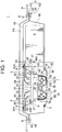
- FIG. 1 schematically illustrates a battery module 1 according to a first embodiment of the present invention.
- the battery module 1 is configured to be attached to a lower face of a vehicle body panel P constituting a vehicle floor F to distribute power to a plurality of loads (not shown) mounted on a vehicle.
- the battery module 1 includes a battery 2, a power distribution unit 3 configured to distribute power to the plurality of loads mounted on the vehicle, and a case 4 housing the battery 2 and the power distribution unit 3.
- the battery module 1 further includes a first wiring member 5 connecting the battery 2 and the power distribution unit 3, a second wiring member 6 connecting the power distribution unit 3 and each load, a third wiring member 7 connecting a later-described base of the power distribution unit 3 and a device mounting portion 32.
- the first wiring member 5, the second wiring member 6 and the third wiring member 7 include electric wires 50, 60 and 70 (conductive members), respectively, and are connected via connector connection to a mating battery connection portion 34, a mating load connection portion 35 and a mating connector connection portion 39, respectively.
- a conductive member such as a bus bar may be used in place of the electric wire.
- the battery 2 and the power distribution unit 3 are arranged side by side along the lower face of the vehicle body panel P.
- a direction in which the battery 2 and the power distribution unit 3 are arranged side by side may be referred to as "right-left direction”
- a direction in which the battery 2 and the power distribution unit 3 are located with respect to the vehicle floor F may be referred to as "downward” and an opposite direction may be referred to as "upward”.
- a direction orthogonal to both of the right-left direction and the up-down direction may be referred to as "anterior-posterior direction”.
- the power distribution unit 3 includes a base 31 and the device mounting portion 32 supported by the base 31 and configured to distribute power from the battery 2 to each load.
- the base 31 includes a plate-like base body 33, a plurality of battery connection portions 34 (in the shown example, two, shown in FIG. 1 ) and a plurality of load connection portions 35 (in the shown example, two, shown in FIG. 1 ) that are provided on a flat face 33A of the base body 33 facing upward (i.e., a face on the vehicle body panel P side), and a support portion 36 formed into a frame-like shape and extending downward from the base body 33 to house and support the device mounting portion 32 therein.
- a face surrounded by the support portion 36 may be referred to as an installation face 36A (installation portion).
- the installation face 36A is arranged to face to a face 38B of the device mounting portion 32 that is located opposite of a mounting face 38A of the device mounting portion 32, and can contact with the face 38B. That is, the device mounting portion 32 is arranged detachable with respect to the installation face 36A of the base 31.
- the battery connection portions 34 and the load connection portions 35 are omitted.
- the base body 33 is provided to and faces to a lower portion of the vehicle body panel P via the case 4. That is, the base body 33 is provided so as to extend in a direction orthogonal to the up-down direction. Further, the base body 33 is provided with base extending pieces 37 at its four corners, which are configured to be overlapped with and fastened by a bolt to later-described case fixing pieces 45 of the case 4. The base extending pieces 37 are formed to extend in the right-left direction from the four corners of the base body 33. With each base extending piece 37 being overlapped with and fastened by a bolt to the later-described case fixing piece 45 (shown in FIG. 1 ) of the case 4, the base body 33 is fixed to the case 4.
- the two battery connection portions 34 are provided at an end of the base body 33 on the battery 2 side (i.e., right side), and the remaining two load connection portions 35 are provided at an end of the base body 33 on the side apart from the battery 2 (i.e., left side).
- Each battery connection portion 34 is connected via connector connection to a second end 5B of the first wiring member 5 having a first end 5A connected to the battery 2.
- the battery 2 and the base 31 are electrically connected to each other.
- Each load connection portion 35 is connected via connector connection to a second end 6A of the second wiring member 6 having a first end connected to each load.
- each load and the base 31 are electrically connected to each other.
- An inner face of the support portion 36 is provided with engagement receive portions (not shown) formed into a frame-like shape and capable of engaging to an engagement portion 380 of the device mounting portion 32.
- the engagement receive portions are provided in a pair and are formed as recesses arranged on each of inner faces of the support portion 36 opposing in the right-left direction.
- the device mounting portion 32 includes electric components 30 such as a relay, a fuse, a ECU and such, and a plate-like mounting portion 38 on which these electric components 30 are mounted.
- electric components 30 such as a relay, a fuse, a ECU and such, and a plate-like mounting portion 38 on which these electric components 30 are mounted.
- the mounting portion 38 includes the mounting face 38A on which the electric components 30 are mounted.
- the mounting portion 38 is installed such that the mounting face 38A faces downward (i.e., away from the vehicle body panel P) .
- the mounting face 38A is provided with the plurality of connector connection portions 39 (shown in FIG. 1 ).
- Each connector connection portion 39 is connected via connector connection to a second end 7B of the third wiring member 7 having a first end 7A connected to the base 31.
- the base 31 and the device mounting portion 32 are electrically connected to each other.
- the base 31 of the power distribution unit 3 is provided with a first connection path (not shown) formed by a conductive member such as a bus bar to electrically connect each battery connection portion 34 with the first end 7A of the third wiring member 8, and a second connection path (not shown) formed by a conductive member such as a bus bar to electrically connect the mounting portion 38 with each load connection portion 35.
- a first connection path (not shown) formed by a conductive member such as a bus bar to electrically connect each battery connection portion 34 with the first end 7A of the third wiring member 8
- a second connection path (not shown) formed by a conductive member such as a bus bar to electrically connect the mounting portion 38 with each load connection portion 35.
- the case 4 includes an upper case 41 and a lower case 42.
- the upper case 41 includes a box-like upper case body 43 opened downward, and a pair of upper extending portions 44, 44 extending in the right-left direction from a lower end of the upper case body 43.
- the case 4 further includes the case fixing piece 45 for fixing the base 31 to the upper case 41.
- the case fixing piece 45 has a first end 45A overlapped with an inner face of the upper case body 43 and fixed thereto using a bolt B, and a second end 45B overlapped with the base extending piece 37 provided to the base 31 and fixed thereto using a bolt B.
- the base 31 is fixed to the upper case 41.
- the base 31 may be fixed to the case 4 using a known fixing method such as welding.
- the lower case 42 includes a box-like lower case body 46 opened downward, an opening 47 providing access to inside the upper case body 43 and the lower case body 46, an access cover 48 covering the opening 47, and a pair of lower extending portions 49, 49 extending in the right-left direction from an upper end of the lower case body 46.
- the opening 47 opens at a lower portion (at a side away from the vehicle body panel P) of the lower case body 46, and is sized to allow an entire of the mounting face 38A of the device mounting portion 32 to be exposed.
- the access cover 48 is sized to cover the opening 47.
- the access cover 48 is fixed to a perimeter of the opening 47 with a bolt B and thereby attached to the lower case body 46.
- a waterproof member such as a packing (not shown) is disposed between the access cover 48 and the perimeter of the opening 47, thereby ensuring sealing property.
- the case 4 is fixed with a bolt B to a perimeter of a recessed portion PA formed on the vehicle body panel P such that the pair of upper extending portions 44, 44 and the pair of lower extending portions 49, 49 are overlapped in the up-down direction and are fastened together to the perimeter of the recessed portion PA.
- the upper case body 43 is accommodated within the recessed portion PA (shown in FIG. 1 ) formed on the vehicle body panel P.
- the case 4 is fixed to the vehicle body panel P using the bolt B, it may be fixed using a known fixing method such as welding.
- the first ends 5A of the first wiring member 5 are electrically connected to the battery 2, and the second ends 5B side of the first wiring member 5 is pulled out to the base 31 side (i.e., to the right side), and then the battery 2 is fixed to the case 4 using a known fixing method.
- Each of the first ends of the second wiring member 6 is electrically connected to each load, and each second end 6A side is pulled out to the base 31 side (i.e., to the left side).
- the electric components 30 are mounted to appropriate locations on the mounting portion 38.
- the access cover 48 is fixed to the perimeter of the opening 47 using a bolt.
- the second ends 5B of the first wiring member 5 are connected via connector connection to the battery connection portion 34 located on the upper face 33A of the base 31, and the second ends 6A of the second wiring member 6 are connected via connector connection to the load connection portion 35.
- the battery 2 and the base 31 are electrically connected, and the base 31 and each load are electrically connected.
- the second end 45B of the case fixing piece 45 with the first end thereof fixed to the upper case body 43 using a bolt, is fixed to the base extending piece 37 using a bolt.
- the base 31 is fixed to the upper case body 43.
- the second ends 7B of the third wiring member 7 with the first ends 7A thereof connected to the base 31, are being pulled out to the support portion 36 side of the base 31.
- the mounting portion 38 side of the device mounting portion 32 is brought close to and inserted to the support portion 36.
- the engagement portion 380 of the mounting portion 38 is engaged to the engagement receive portion of the support portion 36.
- the device mounting portion 32 is attached to the base 31.
- the second end 7B of the third wiring member 7 is connected via connector connection to the connector connection portion 39.
- the pair of lower extending portions 49, 49 of the lower case 42 is overlapped with the pair of upper extending portions 44, 44 of the upper case 41, and the pair of lower extending portions 49, 49 and the pair of upper extending portions 44, 44 are fixed together to the perimeter of the recessed portion PA formed on the vehicle body panel P.
- the battery module 1 is assembled.
- the opening 47 and the access cover 48 of the battery module 1 are provided at the downward side (front side) distant from the vehicle body panel P such that the base 31 and the device mounting portion 32 are located between the opening 47 and the access cover 48, and the vehicle body panel P.
- the access cover 48 is removed and the device mounting portion 32 is exposed.
- the connector connection between the second end 7B of the third wiring member 7 and the connector connection portion 39 is disconnected, and then the engagement between the base 31 and the device mounting portion 32 is disengaged, and the device mounting portion 32 is removed from the base 31 and taken out from the opening 47.
- the entire of the device mounting portion 32 is exchanged, or a part thereof is repaired, and then the device mounting portion 32 is again electrically and mechanically connected to the base 31 according to the reverse procedure.
- the mounting portion 38 of the device mounting portion 32 is inserted into the case 4 through the opening 47 and brought close to and inserted to the support portion 36.
- the engagement portion 380 of the device mounting portion 32 is engaged to the engagement receive portion of the support portion 36.
- the device mounting portion 32 is mechanically connected to the base 31.
- the second end 7B of the third wiring member 7 is connected via connector connection to the connector connection portion 39.
- the device mounting portion 32 is electrically connected to the base 31.
- the access cover 48 is brought close to the opening 47 and fixed thereto using a bolt. In this manner, the maintenance is completed.
- the base 31 is provided with the battery connection portions 34 and the load connection portions 35 at a location facing to the vehicle body panel P constituting the vehicle floor F, and the opening 47 is provided on the front side (downward side) distant from the vehicle body panel P such that the base 31 and the device mounting portion 32 are located between the vehicle body panel P and the opening 47.
- the vehicle can be lifted by a lift and such and an operator works in a position facing upward.
- the opening 47 is positioned at a location easy for the operator to gain access thereto, and since the opening 47 allows the device mounting portion 32 to be exposed, the efficiency of operation in the maintenance of the device mounting portion 32 can be improved.
- the base 31 is provided with the battery connection portions 34 and the load connection portions 35, the maintenance can be performed on the device mounting portion 32 by disconnecting only the connection between the base 31 and the device mounting portion 32. That is, even if the battery connection portions 34 and the load connection portions 35 are provided at a location that is difficult of access, the device mounting portion 32 can be removed without accessing to the battery connection portions 34 and the load connection portions 35, thereby improving the efficiency of operation in the maintenance of the device mounting portion 32.
- the base 31 is provided with the installation face 36A on which the device mounting portion 32 is installed, and the device mounting portion 32 is provided with the connector connection portions 39 to which the electric wires 70 extending from the base 31 are connected, and the connector connection portions 39 are provided on the front side (downward side) distant from the installation face 36A on which the device mounting portion 32 is installed.
- the connector connection portions 39 are positioned at a location easy for the operator to access, the operation to electrically connect or disconnect the base 31 with the device mounting portion 32 during the maintenance of the device mounting portion 32 is made easier, thereby further improving the efficiency of operation in the maintenance of the device mounting portion 32.
- the base 31 is provided with the installation face 36A on which the device mounting portion 32 is installed, and the battery connection portions 34 and the load connection portions 35 are provided at the back side distant from the device mounting portion 32 such that the installation face 36A is located between the battery connection portions 34 and the load connection portions 35, and the device mounting portion 32. Since the battery connection portions 34 and the load connection portions 35 are provided at the back side of the device mounting portion 32 such that the installation face 36A is located between the battery connection portions 34 and the load connection portions 35, and the device mounting portion 32, the operation to disconnect or reconnect the base 31 with the device mounting portion 32 can be performed without being hindered by the battery connection portions 34 and the load connection portions 35 and/or by the wiring members 5, 6 connected thereto.
- the case 4 which houses the battery 2 and the power distribution unit 3 is provided, and the case 4 is provided with the opening 47 for exposing the device mounting portion 32 and the access cover 48 covering this opening 47. Consequently, the device mounting portion 32 can be exposed by removing the access cover 48, thereby further improving the efficiency of operation in the maintenance of the device mounting portion 32 while providing waterproof property for the battery 2 and the power distribution unit 3.
- the third wiring member 7 connecting the base 31 of the power distribution unit 3 and the device mounting portion 32 is provided.
- the base 31 and the device mounting portion 32 are electrically connected to each other.
- the present invention is not limited to this.
- a pair of connection portions 71, 72 for connecting via connector connection the base 31 and the device mounting portion 32 may be provided, as shown in FIG. 4 .
- connection portion 71 of the pair of connection portions 71, 72 may be provided to the installation face 36A (installation portion) of the base 31, and another connection portion 72 of the pair of connection portions 71, 72 may be provided to the face 38B of the mounting portion 38 opposite of the mounting face 38A.
- one connection portion 71 of the pair of connection portions 71, 72 may be provided to an inner face 36C (installation portion) of the support portion 36 of the base 31, and another connection portion 72 of the pair of connection portions 71, 72 may be provided to an end face located between the mounting face 38A of the mounting portion 38 and the face 38B opposite of the mounting face 38A.
- the pair of connection portions 71, 72 may be fitted to each other, thereby electrically connecting the base 31 and the device mounting portion 32.
- the base 31 is provided with each battery connection portion 34 and a third connection path (not shown) that is electrically connected to the one connection portion 71 of the pair of connection portions 71, 72 and that is formed of a conductive member such as a bus bar.
- the power supplied from the battery 2 via the first wiring member 5 is delivered sequentially through the battery connection portion 34, the third connection path of the base 31, the pair of connection portions 71, 72 and the mounting portion 38, and through the electric component 30, and then delivered sequentially through the second connection path of the base 31 and the load connection portion 35, and supplied to each load via the second wiring member 6.
- the pair of connection portions 71, 72 for connecting via connector connection the base 31 and the device mounting portion 32 is provided, and the base 31 is provided with the installation face 36A (or the inner face 36C) as the installation portion on which the device mounting portion 32. Further, the installation face 36A (or the inner face 36C) is provide with one of the pair of the connection portions 71, 72, and the another one of the pair of the connection portions 71, 72 is provided to the device mounting portion 32 and positioned so as to be fitted to the one of the pair of the connection portions 71, 72 when the device mounting portion 32 is installed on the installation face 36A.
- the base 31 and the device mounting portion 32 are connected via connector connection. Consequently, an operation process for electrically connecting the base 31 and the device mounting portion 32 can be omitted.
- the battery connection portions 34 and the load connection portions 35 are provided on the upper face 33A of the base body 33, and each second end 5B, 6A of the first wiring member 5 and the second wiring member 6 are brought close to and fitted to the battery connection portions 34 and the load connection portions 35 from above.
- the present invention is not limited to this. As shown in FIG.
- a battery connection 34B may be provided to a first end face of the base body 33 on the battery 2 side, and the second end 5B of the first wiring member 5 may be brought close to and fitted to the battery connection portion 34B from the right side (horizontal side), while the load connection portion 35B may be provided to a second end face of the base body 33 located opposite of the first end face on the battery 2 side, and the second end 6A of the second wiring member 6 may be brought close to and fitted to the load connection portion 35B from the left side (horizontal side) .
- the base fixing piece 45 may have the first end 45A overlapped with and fixed using a bolt to the inner face of the lower case body 46, and the second end 45B overlapped with and fixed using a bolt to the base extending piece 37 provided to the base 31.
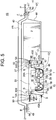
- FIG. 5 schematically shows the battery module 1B according to another modified example of the first embodiment of the present invention.
- elements having the same functions or the same constitution as the first embodiment are denoted by the same reference sign to omit detailed explanation thereof.
- This modified example has the similar advantageous effect with the embodiment described above.
- the battery module 1, 1B is attached to the lower face of the vehicle body panel P constituting the vehicle floor F.
- the battery module may be attached to any appropriate place on the vehicle body panel, for example, it may be attached at the vehicle body panel that is arranged substantially vertically.
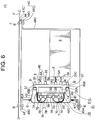
- FIG. 6 is a diagram schematically showing the battery module 1C according to the second embodiment of the present invention.
- elements having the same functions or the same constitution as the first embodiment are denoted by the same reference sign to omit detailed explanation thereof.
- the battery module 1C is configured to be attached to a lower face of a vehicle body panel P constituting a vehicle floor F to distribute power to a plurality of loads (not shown) mounted on a vehicle. Difference between the battery module 1C of the second embodiment and the battery module 1 of the first embodiment exists in the arrangement of a power distribution unit 3, 3C with respect to a battery 2.
- the battery module 1C includes the battery 2, a power distribution unit 3C configured to distribute power to the plurality of loads mounted on the vehicle, and a case 4C housing the battery 2 and the power distribution unit 3C.
- the power distribution unit 3C includes a base 31C and a device mounting portion 32 supported by the base 31C and configured to distribute power from the battery 2 to each load.
- the base 31C includes a plate-like base body 33C, a plurality of battery connection portions 34 (four, in the shown example) and a plurality of load connection portions 35 that are provided on a flat face 33A of the base body 33C, and a support portion 36 formed into a frame-like shape and extending in a direction away from the flat face 33A from the base body 33C to house and support the device mounting portion 32 therein.
- the flat face 33A of the base body 33C is arranged to face a side face of the battery 2
- the support portion 36 is extending in a direction away from the battery 2 such that the base body 33C is located between the support portion 36 and the battery 2.
- the case 4C includes an upper case 41C and a lower case 42C.
- the lower case 42C includes a box-like lower case body 46C opened upward, an opening 47C allowing access to inside the case 4C, an access cover 48C covering the opening 47C, and a pair of lower extending portions 49C, 49C extending in the right-left direction from an upper end of the lower case body 46C.
- the opening 47C is opened to the side of the lower case body 46C (i.e., a direction along the vehicle body panel P and away from the battery 2).
- the vehicle can be lifted by a lift and such and an operator works in a position facing upward.
- the opening 47C is opened in the direction away from the battery 2 (i.e., in the right-left direction)
- the operator does not need to work with his hands lifted.
- physical load on the operator can be reduced compared to the case of the operation requiring the operator to work with his hands lifted. Consequently, the similar advantageous effect as the above-described embodiment can be obtained, that is, the efficiency of operation can be improved during the maintenance of the device mounting portion 32.
Landscapes
- Engineering & Computer Science (AREA)
- Chemical & Material Sciences (AREA)
- Chemical Kinetics & Catalysis (AREA)
- Electrochemistry (AREA)
- General Chemical & Material Sciences (AREA)
- Mechanical Engineering (AREA)
- Manufacturing & Machinery (AREA)
- Transportation (AREA)
- Power Engineering (AREA)
- Combustion & Propulsion (AREA)
- Architecture (AREA)
- Civil Engineering (AREA)
- Structural Engineering (AREA)
- Life Sciences & Earth Sciences (AREA)
- Sustainable Development (AREA)
- Sustainable Energy (AREA)
- Microelectronics & Electronic Packaging (AREA)
- Battery Mounting, Suspending (AREA)
- Arrangement Or Mounting Of Propulsion Units For Vehicles (AREA)
- Connection Or Junction Boxes (AREA)
Abstract
Description
- The present invention relates to a battery module.
- A vehicle battery box mounted on a vehicle and configured to supply power to each load has been disclosed (for example, refer to
Patent Document 1 listed below). A vehicle battery box disclosed inPatent Document 1 includes a battery box and an electric component body housed in a recessed portion formed on the battery box. The battery box includes a built-in battery and is attached to a panel within an engine compartment of the vehicle. The electric component body is a fusible link box having a plurality of fusible links and is electrically connected between each load and the battery, and power is supplied from the battery to each load via this electric component body. - Patent Document 1:
JPH 11-299115 A - In the conventional vehicle battery box, for example during vehicle inspection, the electric component body would need to be removed for repair or exchange (hereinafter referred to as maintenance). However, during that time, connector connection between the electric component body and each load and the battery needs to be disconnected, and thus if the connection location is located at a place difficult of access, then operation efficiency is lowered.
- In view of the above-described problem, an object of the present invention is to provide a battery module which can improve efficiency of operation in the maintenance.
- In order to achieve the above-described object, a first aspect of the present invention provides a battery module including a battery and a power distribution unit connected to the battery and configured to distribute power to a load, wherein the power distribution unit includes a base and a device mounting portion supported by the base and electrically connected to the base to distribute power from the battery to the load, and the base includes a battery connection portion for connection with the battery, and a load connection portion for connection with the load.
- A second aspect of the present invention provides the battery module according to the first aspect, wherein the base includes an installation portion on which the device mounting portion is installed, the device mounting portion is provided with a connector connection portion to which a conductive member extending from the base is connected, and the connector connection portion is provided at a front side of the device mounting portion that is located away from the installation portion.
- A third aspect of the present invention provides the battery module according to the first aspect, further including a pair of connection portions configured to connect via connector connection the base with the device mounting portion, wherein the base includes an installation portion on which the device mounting portion is installed, the installation portion includes one of the pair of the connection portions, and another one of the pair of the connection portions is provided to the device mounting portion and positioned so as to be fitted to the one of the pair of connection portions when the device mounting portion is installed to the installation portion.
- A fourth aspect of the present invention provides the battery module according to any one of the first to third aspect, wherein the base includes an installation portion on which the device mounting portion is installed, and the battery connection portion and the load connection portion are provided at a back side distant from the device mounting portion across the installation portion.
- A fifth aspect of the present invention provides the battery module according to any one of the first to fourth aspects, further including a case housing the battery and the power distribution unit, wherein the case includes an opening configured to allow the device mounting to be exposed, and a cover covering the opening.
- A sixth aspect of the present invention provides the battery module according to the fifth aspect, wherein the case is fixed to a downward side of a vehicle floor, the base is provided with the battery connection portion and the load connection portion at a position facing to the vehicle floor, and the opening is provided at a front side distant from the vehicle floor across the base and the device mounting portion.
- According to the first aspect of the present invention, the power distribution unit includes the base and the device mounting portion supported by the base and electrically connected to the base to distribute power from the battery to the load, and the base includes the battery connection portion for connection with the battery, and the load connection portion for connection with the load. Consequently, during the vehicle inspection, by disconnecting the electrical and mechanical connection between the base and the device mounting portion, the device mounting portion can be removed for repair or exchange (hereinafter referred to as the maintenance). That is, even if the battery connection portion and the load connection portion are located at a location that is difficult of access, the device mounting portion can be removed without accessing the battery connection portion and the load connection portion, thereby improving efficiency of operation in the maintenance.
-
-
FIG. 1 schematically illustrates a battery module according to a first embodiment of the present invention; -
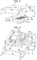
FIG. 2 is a perspective view showing a base and a device mounting portion constituting the battery module; -
FIG. 3 is a perspective view of the base and the device mounting portion shown inFIG. 2 viewed from another angle; -
FIG. 4 is a perspective view schematically showing a modified example of the battery module shown inFIG. 1 ; -
FIG. 5 is a diagram schematically showing another modified example of the battery module shown inFIG. 1 ; and -
FIG. 6 is a diagram schematically showing a battery module according to a second embodiment of the present invention. - In the following, a first embodiment of the present invention will be explained with reference to the drawings.
FIG. 1 schematically illustrates abattery module 1 according to a first embodiment of the present invention. Thebattery module 1 is configured to be attached to a lower face of a vehicle body panel P constituting a vehicle floor F to distribute power to a plurality of loads (not shown) mounted on a vehicle. - As shown in
FIG. 1 , thebattery module 1 includes abattery 2, apower distribution unit 3 configured to distribute power to the plurality of loads mounted on the vehicle, and acase 4 housing thebattery 2 and thepower distribution unit 3. Thebattery module 1 further includes afirst wiring member 5 connecting thebattery 2 and thepower distribution unit 3, asecond wiring member 6 connecting thepower distribution unit 3 and each load, athird wiring member 7 connecting a later-described base of thepower distribution unit 3 and adevice mounting portion 32. Thefirst wiring member 5, thesecond wiring member 6 and thethird wiring member 7 includeelectric wires battery connection portion 34, a matingload connection portion 35 and a matingconnector connection portion 39, respectively. In this embodiment, although thefirst wiring member 5, thesecond wiring member 6 and thethird wiring member 7 includes theelectric wires - The
battery 2 and thepower distribution unit 3 are arranged side by side along the lower face of the vehicle body panel P. In this embodiment, a direction in which thebattery 2 and thepower distribution unit 3 are arranged side by side may be referred to as "right-left direction", a direction in which thebattery 2 and thepower distribution unit 3 are located with respect to the vehicle floor F may be referred to as "downward" and an opposite direction may be referred to as "upward". Further, a direction orthogonal to both of the right-left direction and the up-down direction may be referred to as "anterior-posterior direction". - As shown in
FIGS. 1 and2 , thepower distribution unit 3 includes abase 31 and thedevice mounting portion 32 supported by thebase 31 and configured to distribute power from thebattery 2 to each load. - As shown in
FIGS. 1 and3 , thebase 31 includes a plate-like base body 33, a plurality of battery connection portions 34 (in the shown example, two, shown inFIG. 1 ) and a plurality of load connection portions 35 (in the shown example, two, shown inFIG. 1 ) that are provided on aflat face 33A of thebase body 33 facing upward (i.e., a face on the vehicle body panel P side), and asupport portion 36 formed into a frame-like shape and extending downward from thebase body 33 to house and support thedevice mounting portion 32 therein. With respect to thebase body 33, a face surrounded by thesupport portion 36 may be referred to as aninstallation face 36A (installation portion). With thedevice mounting portion 32 being supported by thesupport portion 36, theinstallation face 36A is arranged to face to aface 38B of thedevice mounting portion 32 that is located opposite of a mountingface 38A of thedevice mounting portion 32, and can contact with theface 38B. That is, thedevice mounting portion 32 is arranged detachable with respect to theinstallation face 36A of thebase 31. InFIG. 2 , thebattery connection portions 34 and theload connection portions 35 are omitted. - In this embodiment, the
base body 33 is provided to and faces to a lower portion of the vehicle body panel P via thecase 4. That is, thebase body 33 is provided so as to extend in a direction orthogonal to the up-down direction. Further, thebase body 33 is provided withbase extending pieces 37 at its four corners, which are configured to be overlapped with and fastened by a bolt to later-describedcase fixing pieces 45 of thecase 4. Thebase extending pieces 37 are formed to extend in the right-left direction from the four corners of thebase body 33. With eachbase extending piece 37 being overlapped with and fastened by a bolt to the later-described case fixing piece 45 (shown inFIG. 1 ) of thecase 4, thebase body 33 is fixed to thecase 4. - As shown in
FIG. 1 , of the twobattery connection portions 34 and the twoload connection portions 35, the twobattery connection portions 34 are provided at an end of thebase body 33 on thebattery 2 side (i.e., right side), and the remaining twoload connection portions 35 are provided at an end of thebase body 33 on the side apart from the battery 2 (i.e., left side). Eachbattery connection portion 34 is connected via connector connection to asecond end 5B of thefirst wiring member 5 having afirst end 5A connected to thebattery 2. As such, thebattery 2 and thebase 31 are electrically connected to each other. Eachload connection portion 35 is connected via connector connection to asecond end 6A of thesecond wiring member 6 having a first end connected to each load. As such, each load and thebase 31 are electrically connected to each other. - An inner face of the
support portion 36 is provided with engagement receive portions (not shown) formed into a frame-like shape and capable of engaging to anengagement portion 380 of thedevice mounting portion 32. The engagement receive portions are provided in a pair and are formed as recesses arranged on each of inner faces of thesupport portion 36 opposing in the right-left direction. - As shown in
FIG. 3 , thedevice mounting portion 32 includeselectric components 30 such as a relay, a fuse, a ECU and such, and a plate-like mounting portion 38 on which theseelectric components 30 are mounted. - The
mounting portion 38 includes themounting face 38A on which theelectric components 30 are mounted. In this embodiment, themounting portion 38 is installed such that themounting face 38A faces downward (i.e., away from the vehicle body panel P) . Further, themounting face 38A is provided with the plurality of connector connection portions 39 (shown inFIG. 1 ). Eachconnector connection portion 39 is connected via connector connection to asecond end 7B of thethird wiring member 7 having afirst end 7A connected to thebase 31. As such, thebase 31 and thedevice mounting portion 32 are electrically connected to each other. - The
base 31 of thepower distribution unit 3 is provided with a first connection path (not shown) formed by a conductive member such as a bus bar to electrically connect eachbattery connection portion 34 with thefirst end 7A of the third wiring member 8, and a second connection path (not shown) formed by a conductive member such as a bus bar to electrically connect themounting portion 38 with eachload connection portion 35. As such, the power supplied from thebattery 2 via thefirst wiring member 5 is delivered sequentially through thebattery connection portion 34, the first connection path of thebase 31, thethird wiring member 7, thedevice mounting portion 32, the second connection path of thebase 31 and theload connection portion 35, and supplied to each load via thesecond wiring member 6. - As shown in
FIG. 1 , thecase 4 includes anupper case 41 and alower case 42. Theupper case 41 includes a box-likeupper case body 43 opened downward, and a pair of upper extendingportions upper case body 43. Thecase 4 further includes thecase fixing piece 45 for fixing the base 31 to theupper case 41. Thecase fixing piece 45 has afirst end 45A overlapped with an inner face of theupper case body 43 and fixed thereto using a bolt B, and asecond end 45B overlapped with thebase extending piece 37 provided to thebase 31 and fixed thereto using a bolt B. As such, thebase 31 is fixed to theupper case 41. In this embodiment, although thebase 31 is fixed to thebase 4 with a bolt using thecase fixing piece 45, thebase 31 may be fixed to thecase 4 using a known fixing method such as welding. - The
lower case 42 includes a box-likelower case body 46 opened downward, anopening 47 providing access to inside theupper case body 43 and thelower case body 46, anaccess cover 48 covering theopening 47, and a pair of lower extendingportions lower case body 46. In this embodiment, theopening 47 opens at a lower portion (at a side away from the vehicle body panel P) of thelower case body 46, and is sized to allow an entire of the mountingface 38A of thedevice mounting portion 32 to be exposed. - The access cover 48 is sized to cover the
opening 47. The access cover 48 is fixed to a perimeter of theopening 47 with a bolt B and thereby attached to thelower case body 46. For example, a waterproof member such as a packing (not shown) is disposed between theaccess cover 48 and the perimeter of theopening 47, thereby ensuring sealing property. - The
case 4 is fixed with a bolt B to a perimeter of a recessed portion PA formed on the vehicle body panel P such that the pair of upper extendingportions portions upper case body 43 is accommodated within the recessed portion PA (shown inFIG. 1 ) formed on the vehicle body panel P. In this embodiment, although thecase 4 is fixed to the vehicle body panel P using the bolt B, it may be fixed using a known fixing method such as welding. - Next, an assembling procedure of the
battery module 1 will be explained. - Firstly, the first ends 5A of the
first wiring member 5 are electrically connected to thebattery 2, and the second ends 5B side of thefirst wiring member 5 is pulled out to the base 31 side (i.e., to the right side), and then thebattery 2 is fixed to thecase 4 using a known fixing method. Each of the first ends of thesecond wiring member 6 is electrically connected to each load, and eachsecond end 6A side is pulled out to the base 31 side (i.e., to the left side). Further, theelectric components 30 are mounted to appropriate locations on the mountingportion 38. Further, theaccess cover 48 is fixed to the perimeter of theopening 47 using a bolt. - The second ends 5B of the
first wiring member 5 are connected via connector connection to thebattery connection portion 34 located on theupper face 33A of thebase 31, and the second ends 6A of thesecond wiring member 6 are connected via connector connection to theload connection portion 35. As such, thebattery 2 and the base 31 are electrically connected, and thebase 31 and each load are electrically connected. Then, with theupper face 33A of the base 31 oriented to face theupper case body 43, thesecond end 45B of thecase fixing piece 45 with the first end thereof fixed to theupper case body 43 using a bolt, is fixed to thebase extending piece 37 using a bolt. As such, thebase 31 is fixed to theupper case body 43. During this time, the second ends 7B of thethird wiring member 7 with the first ends 7A thereof connected to thebase 31, are being pulled out to thesupport portion 36 side of thebase 31. After that, the mountingportion 38 side of thedevice mounting portion 32 is brought close to and inserted to thesupport portion 36. Theengagement portion 380 of the mountingportion 38 is engaged to the engagement receive portion of thesupport portion 36. As such, thedevice mounting portion 32 is attached to thebase 31. Then, thesecond end 7B of thethird wiring member 7 is connected via connector connection to theconnector connection portion 39. The pair of lower extendingportions lower case 42 is overlapped with the pair of upper extendingportions upper case 41, and the pair of lower extendingportions portions battery module 1 is assembled. Theopening 47 and theaccess cover 48 of thebattery module 1 are provided at the downward side (front side) distant from the vehicle body panel P such that thebase 31 and thedevice mounting portion 32 are located between theopening 47 and theaccess cover 48, and the vehicle body panel P. - During the vehicle inspection, to remove the
device mounting portion 32 to repair or exchange the entire of thedevice mounting portion 32 or theelectric component 30 as a part of the device mounting portion 32 (hereinafter referred to as the maintenance), theaccess cover 48 is removed and thedevice mounting portion 32 is exposed. The connector connection between thesecond end 7B of thethird wiring member 7 and theconnector connection portion 39 is disconnected, and then the engagement between the base 31 and thedevice mounting portion 32 is disengaged, and thedevice mounting portion 32 is removed from thebase 31 and taken out from theopening 47. After that, the entire of thedevice mounting portion 32 is exchanged, or a part thereof is repaired, and then thedevice mounting portion 32 is again electrically and mechanically connected to the base 31 according to the reverse procedure. That is, the mountingportion 38 of thedevice mounting portion 32 is inserted into thecase 4 through theopening 47 and brought close to and inserted to thesupport portion 36. Theengagement portion 380 of thedevice mounting portion 32 is engaged to the engagement receive portion of thesupport portion 36. As such, thedevice mounting portion 32 is mechanically connected to thebase 31. After that, thesecond end 7B of thethird wiring member 7 is connected via connector connection to theconnector connection portion 39. As such, thedevice mounting portion 32 is electrically connected to thebase 31. Then, theaccess cover 48 is brought close to theopening 47 and fixed thereto using a bolt. In this manner, the maintenance is completed. - According to the embodiment described above, the
base 31 is provided with thebattery connection portions 34 and theload connection portions 35 at a location facing to the vehicle body panel P constituting the vehicle floor F, and theopening 47 is provided on the front side (downward side) distant from the vehicle body panel P such that thebase 31 and thedevice mounting portion 32 are located between the vehicle body panel P and theopening 47. For example, in case of thebattery module 1 being fixed to the lower face of the vehicle body panel P, the vehicle can be lifted by a lift and such and an operator works in a position facing upward. In this case, since theopening 47 is positioned at a location easy for the operator to gain access thereto, and since theopening 47 allows thedevice mounting portion 32 to be exposed, the efficiency of operation in the maintenance of thedevice mounting portion 32 can be improved. - Furthermore, since the
base 31 is provided with thebattery connection portions 34 and theload connection portions 35, the maintenance can be performed on thedevice mounting portion 32 by disconnecting only the connection between the base 31 and thedevice mounting portion 32. That is, even if thebattery connection portions 34 and theload connection portions 35 are provided at a location that is difficult of access, thedevice mounting portion 32 can be removed without accessing to thebattery connection portions 34 and theload connection portions 35, thereby improving the efficiency of operation in the maintenance of thedevice mounting portion 32. - Furthermore, the
base 31 is provided with theinstallation face 36A on which thedevice mounting portion 32 is installed, and thedevice mounting portion 32 is provided with theconnector connection portions 39 to which theelectric wires 70 extending from the base 31 are connected, and theconnector connection portions 39 are provided on the front side (downward side) distant from theinstallation face 36A on which thedevice mounting portion 32 is installed. As such, since theconnector connection portions 39 are positioned at a location easy for the operator to access, the operation to electrically connect or disconnect the base 31 with thedevice mounting portion 32 during the maintenance of thedevice mounting portion 32 is made easier, thereby further improving the efficiency of operation in the maintenance of thedevice mounting portion 32. - Furthermore, the
base 31 is provided with theinstallation face 36A on which thedevice mounting portion 32 is installed, and thebattery connection portions 34 and theload connection portions 35 are provided at the back side distant from thedevice mounting portion 32 such that theinstallation face 36A is located between thebattery connection portions 34 and theload connection portions 35, and thedevice mounting portion 32. Since thebattery connection portions 34 and theload connection portions 35 are provided at the back side of thedevice mounting portion 32 such that theinstallation face 36A is located between thebattery connection portions 34 and theload connection portions 35, and thedevice mounting portion 32, the operation to disconnect or reconnect the base 31 with thedevice mounting portion 32 can be performed without being hindered by thebattery connection portions 34 and theload connection portions 35 and/or by thewiring members - Furthermore, the
case 4 which houses thebattery 2 and thepower distribution unit 3 is provided, and thecase 4 is provided with theopening 47 for exposing thedevice mounting portion 32 and theaccess cover 48 covering thisopening 47. Consequently, thedevice mounting portion 32 can be exposed by removing theaccess cover 48, thereby further improving the efficiency of operation in the maintenance of thedevice mounting portion 32 while providing waterproof property for thebattery 2 and thepower distribution unit 3. - In the first embodiment described above, the
third wiring member 7 connecting thebase 31 of thepower distribution unit 3 and thedevice mounting portion 32 is provided. By connecting thefirst end 7A of thethird wiring member 7 to thebase 31, and by fitting thesecond end 7B to theconnector connection portion 39 of thedevice mounting portion 32, thebase 31 and thedevice mounting portion 32 are electrically connected to each other. However, the present invention is not limited to this. In place of thethird wiring member 7, a pair ofconnection portions base 31 and thedevice mounting portion 32 may be provided, as shown inFIG. 4 . Oneconnection portion 71 of the pair ofconnection portions installation face 36A (installation portion) of thebase 31, and anotherconnection portion 72 of the pair ofconnection portions face 38B of the mountingportion 38 opposite of the mountingface 38A. Alternatively, oneconnection portion 71 of the pair ofconnection portions inner face 36C (installation portion) of thesupport portion 36 of thebase 31, and anotherconnection portion 72 of the pair ofconnection portions face 38A of the mountingportion 38 and theface 38B opposite of the mountingface 38A. Then, when thedevice mounting portion 32 is installed on the installation face 36A and thebase 31 is attached to thedevice mounting portion 32, the pair ofconnection portions base 31 and thedevice mounting portion 32. In this case, thebase 31 is provided with eachbattery connection portion 34 and a third connection path (not shown) that is electrically connected to the oneconnection portion 71 of the pair ofconnection portions battery 2 via thefirst wiring member 5 is delivered sequentially through thebattery connection portion 34, the third connection path of thebase 31, the pair ofconnection portions portion 38, and through theelectric component 30, and then delivered sequentially through the second connection path of thebase 31 and theload connection portion 35, and supplied to each load via thesecond wiring member 6. - As described above, the pair of
connection portions base 31 and thedevice mounting portion 32 is provided, and thebase 31 is provided with theinstallation face 36A (or theinner face 36C) as the installation portion on which thedevice mounting portion 32. Further, theinstallation face 36A (or theinner face 36C) is provide with one of the pair of theconnection portions connection portions device mounting portion 32 and positioned so as to be fitted to the one of the pair of theconnection portions device mounting portion 32 is installed on theinstallation face 36A. That is, with thedevice mounting portion 32 installed on the installation face 36A and the pair ofconnection portions base 31 and thedevice mounting portion 32 are connected via connector connection. Consequently, an operation process for electrically connecting thebase 31 and thedevice mounting portion 32 can be omitted. - Furthermore, in the first embodiment described above, the
battery connection portions 34 and theload connection portions 35 are provided on theupper face 33A of thebase body 33, and eachsecond end first wiring member 5 and thesecond wiring member 6 are brought close to and fitted to thebattery connection portions 34 and theload connection portions 35 from above. However, the present invention is not limited to this. As shown inFIG. 5 , in abattery module 1B, abattery connection 34B may be provided to a first end face of thebase body 33 on thebattery 2 side, and thesecond end 5B of thefirst wiring member 5 may be brought close to and fitted to thebattery connection portion 34B from the right side (horizontal side), while theload connection portion 35B may be provided to a second end face of thebase body 33 located opposite of the first end face on thebattery 2 side, and thesecond end 6A of thesecond wiring member 6 may be brought close to and fitted to theload connection portion 35B from the left side (horizontal side) . In this case, thebase fixing piece 45 may have thefirst end 45A overlapped with and fixed using a bolt to the inner face of thelower case body 46, and thesecond end 45B overlapped with and fixed using a bolt to thebase extending piece 37 provided to thebase 31.FIG. 5 schematically shows thebattery module 1B according to another modified example of the first embodiment of the present invention. InFIG. 5 , elements having the same functions or the same constitution as the first embodiment are denoted by the same reference sign to omit detailed explanation thereof. This modified example has the similar advantageous effect with the embodiment described above. - Furthermore, in the first embodiment described above, the
battery module - Next, a
battery module 1C according to a second embodiment of the present invention will be explained with reference to the drawings.FIG. 6 is a diagram schematically showing thebattery module 1C according to the second embodiment of the present invention. InFIG. 6 , elements having the same functions or the same constitution as the first embodiment are denoted by the same reference sign to omit detailed explanation thereof. Thebattery module 1C is configured to be attached to a lower face of a vehicle body panel P constituting a vehicle floor F to distribute power to a plurality of loads (not shown) mounted on a vehicle. Difference between thebattery module 1C of the second embodiment and thebattery module 1 of the first embodiment exists in the arrangement of apower distribution unit battery 2. - As shown in
FIG. 6 , thebattery module 1C includes thebattery 2, apower distribution unit 3C configured to distribute power to the plurality of loads mounted on the vehicle, and a case 4C housing thebattery 2 and thepower distribution unit 3C. - As shown in
FIG. 6 , thepower distribution unit 3C includes abase 31C and adevice mounting portion 32 supported by thebase 31C and configured to distribute power from thebattery 2 to each load. - the
base 31C includes a plate-like base body 33C, a plurality of battery connection portions 34 (four, in the shown example) and a plurality ofload connection portions 35 that are provided on aflat face 33A of thebase body 33C, and asupport portion 36 formed into a frame-like shape and extending in a direction away from theflat face 33A from thebase body 33C to house and support thedevice mounting portion 32 therein. In thebattery module 1C of this embodiment, theflat face 33A of thebase body 33C is arranged to face a side face of thebattery 2, and thesupport portion 36 is extending in a direction away from thebattery 2 such that thebase body 33C is located between thesupport portion 36 and thebattery 2. - The case 4C includes an
upper case 41C and a lower case 42C. The lower case 42C includes a box-like lower case body 46C opened upward, anopening 47C allowing access to inside the case 4C, anaccess cover 48C covering theopening 47C, and a pair of lower extendingportions opening 47C is opened to the side of the lower case body 46C (i.e., a direction along the vehicle body panel P and away from the battery 2). - During the vehicle inspection, for example, in the case where the
battery module 1C is fixed to the lower face of the vehicle body panel P, the vehicle can be lifted by a lift and such and an operator works in a position facing upward. In this case, since theopening 47C is opened in the direction away from the battery 2 (i.e., in the right-left direction), the operator does not need to work with his hands lifted. Thus, as in the first embodiment, physical load on the operator can be reduced compared to the case of the operation requiring the operator to work with his hands lifted. Consequently, the similar advantageous effect as the above-described embodiment can be obtained, that is, the efficiency of operation can be improved during the maintenance of thedevice mounting portion 32. - Preferred constitution and method and such to implement the present invention have been disclosed herein. However, the present invention is not limited to these. That is, although the present invention has been illustrated and shown mainly with respect to a certain embodiment, it will be apparent to a skilled person in the art that various changes can be made to the embodiments described above regarding shape, material, number and other detailed constitution without departing from the spirit and object of the present invention. Description that may limit the shape, material and such disclosed herein is described for the illustrative purpose only to enhance understanding of the present invention, and thus is not intended to limit the present invention. Therefore, description using name of a member without those limitations, either entire limitation or a part of limitation, regarding the shape, material and such, is also within the present invention.
-
- 1, 1A, 1B, 1C
- battery module
- 2
- battery
- 3, 3C
- power distribution unit
- 4, 4C
- case
- 31, 31C
- base
- 32
- device mounting portion
- 34, 34B
- battery connection portion
- 35, 35B
- load connection portion
- 36A
- installation face (installation portion)
- 36C
- inner face (installation portion)
- 39
- connector connection portion
- 47, 47C
- opening
- 48, 48C
- cover (access cover)
- 70
- electric wire (conductive member)
- 71, 72
- pair of connection portions
- F
- vehicle floor
Claims (6)
- A battery module comprising:a battery; anda power distribution unit connected to the battery and configured to distribute power to a load, whereinthe power distribution unit includes a base and a device mounting portion supported by the base and electrically connected to the base to distribute power from the battery to the load, andthe base includes a battery connection portion for connection with the battery, and a load connection portion for connection with the load.
- The battery module according to claim 1, wherein
the base includes an installation portion on which the device mounting portion is installed,
the device mounting portion is provided with a connector connection portion to which a conductive member extending from the base is connected, and
the connector connection portion is provided at a front side of the device mounting portion that is located away from the installation portion. - The battery module according to claim 1, further comprising a pair of connection portions configured to connect via connector connection the base with the device mounting portion, wherein
the base includes an installation portion on which the device mounting portion is installed,
the installation portion includes one of the pair of the connection portions, and
another one of the pair of the connection portions is provided to the device mounting portion and positioned so as to be fitted to the one of the pair of connection portions when the device mounting portion is installed to the installation portion. - The battery module according to any one of claims 1-3, wherein
the base includes an installation portion on which the device mounting portion is installed, and
the battery connection portion and the load connection portion are provided at a back side distant from the device mounting portion across the installation portion. - The battery module according to any one of claims 1-4, further comprising a case housing the battery and the power distribution unit, wherein
the case includes an opening configured to allow the device mounting to be exposed, and a cover covering the opening. - The battery module according to claim 5, wherein
the case is fixed to a downward side of a vehicle floor,
the base is provided with the battery connection portion and the load connection portion at a position facing to the vehicle floor, and
the opening is provided at a front side distant from the vehicle floor across the base and the device mounting portion.
Applications Claiming Priority (1)
| Application Number | Priority Date | Filing Date | Title |
|---|---|---|---|
| JP2018100435A JP7168346B2 (en) | 2018-05-25 | 2018-05-25 | battery module |
Publications (1)
| Publication Number | Publication Date |
|---|---|
| EP3573134A1 true EP3573134A1 (en) | 2019-11-27 |
Family
ID=66647243
Family Applications (1)
| Application Number | Title | Priority Date | Filing Date |
|---|---|---|---|
| EP19176423.2A Pending EP3573134A1 (en) | 2018-05-25 | 2019-05-24 | Battery module |
Country Status (4)
| Country | Link |
|---|---|
| US (1) | US10700320B2 (en) |
| EP (1) | EP3573134A1 (en) |
| JP (1) | JP7168346B2 (en) |
| CN (1) | CN110525356B (en) |
Families Citing this family (4)
| Publication number | Priority date | Publication date | Assignee | Title |
|---|---|---|---|---|
| DE102018106399A1 (en) * | 2018-03-19 | 2019-09-19 | Muhr Und Bender Kg | Housing arrangement for receiving electrical storage means and method for producing a housing assembly |
| JP7136762B2 (en) | 2019-12-17 | 2022-09-13 | 本田技研工業株式会社 | power storage device |
| JP2024024758A (en) * | 2022-08-10 | 2024-02-26 | トヨタ自動車株式会社 | Vehicle front structure |
| US12570162B2 (en) * | 2023-10-30 | 2026-03-10 | Kubota Corporation | Electric work vehicle |
Citations (4)
| Publication number | Priority date | Publication date | Assignee | Title |
|---|---|---|---|---|
| US5643693A (en) * | 1995-10-30 | 1997-07-01 | Yazaki Corporation | Battery-mounted power distribution module |
| JPH11299115A (en) | 1998-04-10 | 1999-10-29 | Yazaki Corp | Vehicle battery box |
| WO2014107094A1 (en) * | 2013-01-07 | 2014-07-10 | 에스케이이노베이션 주식회사 | Sensing assembly for secondary battery module and secondary battery module provided with sensing assembly |
| US20160197320A1 (en) * | 2015-01-05 | 2016-07-07 | Johnson Controls Technology Company | Snap-in extensions and guide walls for bus bar bridges of a battery module |
Family Cites Families (7)
| Publication number | Priority date | Publication date | Assignee | Title |
|---|---|---|---|---|
| JP2005262894A (en) * | 2004-03-16 | 2005-09-29 | Toyota Motor Corp | Vehicle with high voltage line |
| FR2906416B1 (en) * | 2006-09-22 | 2009-05-08 | Valeo Equip Electr Moteur | INTEGRATED MICRO-HYBRID DEVICE FOR A MOTOR VEHICLE AND MICRO-HYBRID DEVICE INCORPORATING IT |
| JP5811027B2 (en) * | 2012-05-17 | 2015-11-11 | 三菱自動車工業株式会社 | Inverter cover |
| CN103770611A (en) * | 2012-10-24 | 2014-05-07 | Alte动力科技股份有限公司 | Structural cover for power electronics enclosing a vehicle battery module and method for repairing and manufacturing a vehicle using the same |
| WO2014171559A1 (en) * | 2013-04-15 | 2014-10-23 | 주식회사 엘지화학 | Battery module having novel structure and battery pack comprising same |
| JP6335960B2 (en) | 2016-03-18 | 2018-05-30 | 矢崎総業株式会社 | Branch box |
| KR102120664B1 (en) * | 2016-05-25 | 2020-06-09 | 닛산 지도우샤 가부시키가이샤 | Mounting structure of power converter |
-
2018
- 2018-05-25 JP JP2018100435A patent/JP7168346B2/en active Active
-
2019
- 2019-04-25 US US16/394,681 patent/US10700320B2/en active Active
- 2019-04-25 CN CN201910340367.0A patent/CN110525356B/en active Active
- 2019-05-24 EP EP19176423.2A patent/EP3573134A1/en active Pending
Patent Citations (4)
| Publication number | Priority date | Publication date | Assignee | Title |
|---|---|---|---|---|
| US5643693A (en) * | 1995-10-30 | 1997-07-01 | Yazaki Corporation | Battery-mounted power distribution module |
| JPH11299115A (en) | 1998-04-10 | 1999-10-29 | Yazaki Corp | Vehicle battery box |
| WO2014107094A1 (en) * | 2013-01-07 | 2014-07-10 | 에스케이이노베이션 주식회사 | Sensing assembly for secondary battery module and secondary battery module provided with sensing assembly |
| US20160197320A1 (en) * | 2015-01-05 | 2016-07-07 | Johnson Controls Technology Company | Snap-in extensions and guide walls for bus bar bridges of a battery module |
Also Published As
| Publication number | Publication date |
|---|---|
| CN110525356B (en) | 2023-07-21 |
| JP7168346B2 (en) | 2022-11-09 |
| US20190363322A1 (en) | 2019-11-28 |
| US10700320B2 (en) | 2020-06-30 |
| JP2019202709A (en) | 2019-11-28 |
| CN110525356A (en) | 2019-12-03 |
Similar Documents
| Publication | Publication Date | Title |
|---|---|---|
| EP3573134A1 (en) | Battery module | |
| CN101752147B (en) | Plug-in unit | |
| JP4419765B2 (en) | Battery pack device | |
| JPH08185921A (en) | Electrical junction box | |
| RU2476334C2 (en) | Modular assembly of power distribution and method of its fabrication | |
| JP4218232B2 (en) | Junction box | |
| KR101006463B1 (en) | Integral Standard Distribution Board | |
| JP2005130633A (en) | Electrical junction box | |
| KR101779004B1 (en) | Block for vehicle having busbar assembly | |
| KR102517859B1 (en) | Junction block with joint unit | |
| JP4306602B2 (en) | Electrical junction box | |
| JPH10174254A (en) | Electrical connection structure of electrical connection box | |
| KR20100084891A (en) | Fuse box | |
| JP3916283B2 (en) | Junction box | |
| JP7751992B2 (en) | Electric vehicle charging equipment | |
| JP2006228627A (en) | Cover structure of electrical unit | |
| JP3125999U (en) | switchboard | |
| JP4598376B2 (en) | Trunk board | |
| JPH0819122A (en) | Metal closed switchgear | |
| JP4029588B2 (en) | Electrical junction box for automobiles | |
| JP2023116325A (en) | Power supply system and connection method | |
| JP2024072681A (en) | Electrical Junction Box | |
| JP2024138747A (en) | Bus duct branching device and power branching device | |
| JP5828317B2 (en) | Electrical junction box | |
| KR200464160Y1 (en) | Multi-fuse mounting structure |
Legal Events
| Date | Code | Title | Description |
|---|---|---|---|
| PUAI | Public reference made under article 153(3) epc to a published international application that has entered the european phase |
Free format text: ORIGINAL CODE: 0009012 |
|
| STAA | Information on the status of an ep patent application or granted ep patent |
Free format text: STATUS: REQUEST FOR EXAMINATION WAS MADE |
|
| 17P | Request for examination filed |
Effective date: 20190524 |
|
| AK | Designated contracting states |
Kind code of ref document: A1 Designated state(s): AL AT BE BG CH CY CZ DE DK EE ES FI FR GB GR HR HU IE IS IT LI LT LU LV MC MK MT NL NO PL PT RO RS SE SI SK SM TR |
|
| AX | Request for extension of the european patent |
Extension state: BA ME |
|
| RBV | Designated contracting states (corrected) |
Designated state(s): AL AT BE BG CH CY CZ DE DK EE ES FI FR GB GR HR HU IE IS IT LI LT LU LV MC MK MT NL NO PL PT RO RS SE SI SK SM TR |
|
| STAA | Information on the status of an ep patent application or granted ep patent |
Free format text: STATUS: EXAMINATION IS IN PROGRESS |
|
| 17Q | First examination report despatched |
Effective date: 20210825 |
|
| RAP3 | Party data changed (applicant data changed or rights of an application transferred) |
Owner name: YAZAKI CORPORATION |