EP3572819B1 - Verfahren zur bestimmung räumlicher konfigurationen von einer vielzahl von wandlern in bezug auf ein zielobjekt - Google Patents
Verfahren zur bestimmung räumlicher konfigurationen von einer vielzahl von wandlern in bezug auf ein zielobjekt Download PDFInfo
- Publication number
- EP3572819B1 EP3572819B1 EP18174296.6A EP18174296A EP3572819B1 EP 3572819 B1 EP3572819 B1 EP 3572819B1 EP 18174296 A EP18174296 A EP 18174296A EP 3572819 B1 EP3572819 B1 EP 3572819B1
- Authority
- EP
- European Patent Office
- Prior art keywords
- transducers
- subset
- target object
- spatial configurations
- sensor signals
- Prior art date
- Legal status (The legal status is an assumption and is not a legal conclusion. Google has not performed a legal analysis and makes no representation as to the accuracy of the status listed.)
- Active
Links
Images


Classifications
-
- G—PHYSICS
- G06—COMPUTING OR CALCULATING; COUNTING
- G06F—ELECTRIC DIGITAL DATA PROCESSING
- G06F3/00—Input arrangements for transferring data to be processed into a form capable of being handled by the computer; Output arrangements for transferring data from processing unit to output unit, e.g. interface arrangements
- G06F3/01—Input arrangements or combined input and output arrangements for interaction between user and computer
- G06F3/03—Arrangements for converting the position or the displacement of a member into a coded form
- G06F3/033—Pointing devices displaced or positioned by the user, e.g. mice, trackballs, pens or joysticks; Accessories therefor
- G06F3/0346—Pointing devices displaced or positioned by the user, e.g. mice, trackballs, pens or joysticks; Accessories therefor with detection of the device orientation or free movement in a three-dimensional [3D] space, e.g. 3D mice, 6-DOF [six degrees of freedom] pointers using gyroscopes, accelerometers or tilt-sensors
-
- G—PHYSICS
- G01—MEASURING; TESTING
- G01P—MEASURING LINEAR OR ANGULAR SPEED, ACCELERATION, DECELERATION, OR SHOCK; INDICATING PRESENCE, ABSENCE, OR DIRECTION, OF MOVEMENT
- G01P21/00—Testing or calibrating of apparatus or devices covered by the preceding groups
-
- H—ELECTRICITY
- H04—ELECTRIC COMMUNICATION TECHNIQUE
- H04L—TRANSMISSION OF DIGITAL INFORMATION, e.g. TELEGRAPHIC COMMUNICATION
- H04L67/00—Network arrangements or protocols for supporting network services or applications
- H04L67/01—Protocols
- H04L67/12—Protocols specially adapted for proprietary or special-purpose networking environments, e.g. medical networks, sensor networks, networks in vehicles or remote metering networks
Definitions
- the present disclosure relates to a method of determining spatial configurations of a plurality of transducers, in particular accelerometers, relative to a target object, the plurality of transducers being attached to the target object.
- multiple transducers such as accelerometers
- a target object e.g. using an adhesive or a suitable mounting device.
- the position and spatial orientation, of the individual transducers relative to the target object typically need to be established with a reasonable accuracy in order to facilitate useful measurement results.
- spatial configuration of a body refers to the position and the orientation of the body relative to a suitable reference coordinate system.
- the checking and verification of the spatial configurations, i.e. positions and orientations, of multiple transducers of large measurement set-ups remain a considerable challenge in numerous types of applications, such as in structural analysis, vibration measurement, etc.
- the number of measurement locations on the target object grows. This is typically followed by a corresponding growth in the number of transducers contained in the measurement set-up.
- many target objects have a complicated geometry including complicated surface structures which render the determination of the spatial configurations of the transducers difficult.
- TEDS Transducer Electronic Data Sheet
- Each TEDS compliant transducer is capable of transmitting its stored transducer information to a remote measurement system or equipment via a standardized communication protocol.
- the remote measurement system may automatically load the transducer information directly into a set-up description or file of the measurement system. This feature may therefore reduce human errors associated with manually entering the transducer data into the measurement system.
- each transducer in such measurement set-ups remains a significant challenge.
- the appropriate spatial configurations of the transducers are important in numerous types of vibration measurements to ensure the intended or at least known component of e.g. acceleration is measured by the transducer at the intended or at least known position.
- WO 2016/135198 discloses a method of detecting a spatial orientation of a transducer by a handheld optical scanning device. To this end, this prior art method uses a spatial orientation feature on an outer housing surface of the transducer.
- WO 02/059627 discloses a system and method for calibrating an accelerometer assembly.
- a computer-implemented method of determining respective spatial configurations, indicative of respective positions and orientations, of a plurality of transducers attached to a target object as defined in appended claim 1.
- the method comprises:
- the inventors have realized that the spatial configurations of multiple transducers, including their positions and orientations relative to a target object to which they are attached, may efficiently be determined at a sufficiently high accuracy based on the sensor signals from the multiple of transducers and possibly other transducers attached to the target object. Accordingly, the need for manually measuring the positions and orientations of all transducers attached to a body is eliminated or at least greatly reduced. Consequently, the time and effort needed to establish the spatial configurations of all transducers is greatly reduced, in particularly when the subset of transducers includes a large number of transducers.
- the method receives information representing only a part of the spatial configurations of the plurality of transducers as an input. Hence, the process only needs to determine a remaining part of the spatial configurations in order to establish the complete spatial configurations of all transducers of the plurality of transducers.
- Said information includes the spatial configurations of a first subset of transducers, in particular information defining both the positions and the orientations of the transducers of a first subset. To this end the information may include information representing coordinates along six degrees of freedom (three positions and three rotational degrees of freedom) for each transducer of the first subset of the transducers. Alternatively or additionally, the information may include spatial relationships between at least a first subset of transducers.
- the spatial relationships may be relative distances between pairs of transducers, partial information about the orientation of the transducers, e.g. a direction of one axis of a measurement coordinate system of the transducer, or other partial spatial configurations representing coordinates along fewer than six degrees of freedom, e.g. coordinates along one or two or three degrees of freedom.
- the received information representing only a part of the spatial configurations of the plurality of transducers may represent complete spatial configurations of only a first subset of the transducers and/or partial spatial configurations of at least a first subset of the transducers.
- the spatial configurations of the second subset of transducers may be automatically determined from their respective sensor signals and from the known spatial configurations of the first subset. Consequently, the time and effort needed to establish the spatial configurations of all transducers is greatly reduced, in particular since the first subset of transducers may be much smaller than the second subset of transducers. For example, if one hundred or more transducers are attached to a target object it may be sufficient to include only few of them, e.g. only three transducers, into the first subset. Once the spatial configurations of these have been established, e.g.
- the spatial configurations of all remaining transducers may be automatically determined.
- the transducers of the first subset will also be referred to as reference transducers.
- the spatial configuration of a transducer attached to a target object may be expressed as a transformation between a measurement coordinate system of the transducer and a local coordinate system of the target object.
- the spatial configuration of a transducer attached to a target object may be expressed as a transformation between a measurement coordinate system of the transducer and a global coordinate system.
- the measurement coordinate system of the transducer may define the axes along which accelerations are measured by the transducer.
- Each transducer may be or comprise a single-axis or multi-axis, e.g. triaxial, accelerometer.
- the sensor signals from a transducer may represent one or more series of measurements by said transducer. For example, each measurement may be indicative of accelerations along one or more directions, e.g. in three directions.
- a triaxial accelerometer may provide a time series of measurements, where each measurement represents an acceleration vector relative to a measurement coordinate system of the accelerometer.
- Other examples of transducers include strain gauges, proximity probes and inclinometers or other measurement devices operable to measure movements, accelerations, forces or other quantities from which movements of the target object can be derived.
- the spatial configurations of the transducers of the first subset may be obtained in any suitable manner, e.g. determined and entered manually.
- the transducers of the first subset may be mounted to the target object at easily identifiable positions on the surface of the target object, e.g. at some distinct features of the target object's geometry that may be used as "anchor points" to place the transducers.
- the transducers may be mounted at said positions using spirit levels and/or swivel bases so as to align the transducers relative to the direction of gravity.
- the thus identified positions and orientations may manually be entered into a suitable measurement system, e.g. using a suitable digital 3D model, e.g. a CAD model, of the target object.
- obtaining the spatial configurations of the transducers of the first subset comprises receiving the spatial configurations of the transducers of the first subset as an input.
- the process does not receive the precise spatial configurations of the transducers of the first subset but merely information indicative of a set of spatial relationships between the transducers of the first subset. The process then computes, from the received information and from the received sensor signals, the spatial configuration of the transducers of the first subset.
- the first subset comprises a number of transducers sufficient to measure movement of the target object along all its degrees of freedom.
- the number of transducers may be selected sufficient to measure movement of the target object along six degrees of freedom, namely three translatory degrees of freedom and three rotational degrees of freedom.
- the exact number of transducers required depends on the capabilities of the transducers and of their relative positions relative to the target object and of the number of degrees of freedom of movement of the target object.
- the transducers are triaxial accelerometers
- three transducers are sufficient for forming the first subset when the three transducers are not positioned along a straight line.
- the three transducers should also be positioned sufficiently far from each other or at least as far from each other as the geometry of the target object permits.
- the method comprises verifying whether the first subset includes a sufficient number of transducers and/or whether the transducers are adequately positioned.
- each transducer may be associated with a transducer transmissibility matrix representing a transformation between accelerations, in particular translational and rotational accelerations, of the transducer relative to a local coordinate system of the target object to accelerations measured by said transducer along the axes of a measurement coordinate system of the transducer.
- the transducer transmissibility matrix of a transducer attached to a target object represents the position and orientation of a measurement coordinate system of the transducer relative to a local coordinate system of the target object.
- the process comprises determining whether the induced movement is sufficient for determining the spatial configuration of the transducers, e.g. the transducers of the second subset of transducers.
- determining whether the caused movement is sufficient for determining the spatial configuration of the transducers of the second subset of transducers comprises:
- the method comprises filtering the recorded signals so as to supress frequencies associated with flexural modes of the induced movements.
- the method comprises low-pass filtering of the sensor signals.
- the process may comprise detecting a natural frequency of a lowest flexural mode and a natural frequency of the highest rigid-body mode; selecting a cut-off frequency of the low-pass filter so as to suppress at least a majority of the flexural modes and to maintain at least a majority of the rigid body modes.
- Computing the object accelerations may comprise computing a least-squares solution to a system of linear equations, each linear equation representing a transformation between measured accelerations, measured by one of the reference accelerometers, and unknown object accelerations.
- the process receives information indicative of a set of spatial relationships between the transducers of the first subset; and the process computes, from the received information and from the received sensor signals, the spatial configuration of the transducers of the first subset.
- the information about the spatial relationship between the transducers of the first subset may include the distances between respective pairs of transducers of the first subset.
- the information about the spatial relationship between the transducers of the first subset may include a combination of relative distances and orientations or another combination of spatial parameters.
- Computing the spatial configurations of the transducers of the first subset may comprise:
- some embodiments of the method described herein may be performed in respect of a target object that is suspended or otherwise supported so as to allow movement of the target object in all six degrees of freedom.
- inventions disclosed herein may be performed in respect of a deformable target object whose motion is restricted (e.g. along one or more degrees of freedom) by an object support.
- some embodiments of the method comprise:
- the time-dependent acceleration coefficients may be coefficients associated with modal coordinates of the target objects.
- the procedure for computing the coefficients may be similar to e.g. obtaining modal coordinates in modal decomposition.
- the time-dependent acceleration coefficients may be coefficients of another expansion based on a suitable set of basis functions.
- a suitable set of basis functions should preferably satisfy a set of boundary conditions, e.g. so-called essential boundary conditions, and be mutually orthogonal.
- processing means comprises any circuit and/or device suitably adapted to perform the above functions.
- processing means comprises general- or special-purpose programmable microprocessors, Digital Signal Processors (DSP), Application Specific Integrated Circuits (ASIC), Programmable Logic Arrays (PLA), Field Programmable Gate Arrays (FPGA), Graphical Processing Units (GPU), special purpose electronic circuits, etc., or a combination thereof.
- the present disclosure relates to different aspects, including the method described above and in the following, further methods, systems, devices and product means, each yielding one or more of the benefits and advantages described in connection with one or more of the other aspects, and each having one or more embodiments corresponding to the embodiments described in connection with one or more of the other aspects described herein and/or as disclosed in the appended claims.
- the further sensor signals may be obtained based on movements suitable for performing the intended structural analysis calculations.
- the further sensor signals may be indicative of movements of the respective transducers during a further induced movement of the target object different from the induced movement from which the spatial configurations of the transducers has been determined.
- the further induced movement may include flexural movements in addition or alternative to rigid body movements.
- the further induced movement may or may not include rigid-body movements along all six degrees of freedom.
- Yet another aspect disclosed herein relates to embodiments of a method of determining spatial configurations of a plurality of transducers attached to a target object; the plurality of transducers comprising a first subset of transducers and a second subset of transducers; the method comprising:
- the spatial configurations of the transducers of the first subset may be obtained prior to inducing the movement of the target object and/or prior to receiving the sensor signals. However, it will be appreciated that, in embodiments where the spatial configurations of the transducers of the first subset are determined based on the received sensor signals, the spatial configurations of the transducers of the first subset are obtained after receipt of said sensor signals.
- Inducing movement of the target object may comprise exerting one or more forces onto the target object, e.g. by manually swinging the target object and/or by impacting the target object with an excitation hammer.
- the movement should include components along all available degrees of freedom.
- the induced movement should include components along three orthogonal directions and rotational components around three linearly independent axes.
- the target object may be suspended from elastic bands, supported on air cushions or otherwise supported such that the object may perform at least small movements along three orthogonal directions and at least small rotations around three linearly independent axes.
- the target object may be supported such that its movement is constrained along one or more degrees of freedom, as will be described in greater detail below.
- the induced further movement based on which the structural analysis is performed may also include significant flexural movements which do not need to be suppressed but which may, in fact, be of interest for the purpose of the structural analysis.
- a computer program may comprise program code means adapted to cause a data processing system to perform the steps of the computer-implemented method disclosed above and in the following when the program code means are executed on the data processing system.
- the computer program may be stored on a computer-readable storage medium or embodied as a data signal.
- the storage medium may comprise any suitable circuitry or device for storing data, such as a RAM, a ROM, an EPROM, EEPROM, flash memory, magnetic or optical storage device, such as a CD ROM, a DVD, a hard disk, and/or the like.
- Yet another aspect disclosed herein relates to embodiments of a measurement system comprising a data processing system configured to perform the steps of the computer-implemented method described herein.
- the measurement system further comprises:
- the measurement system may comprise a display showing the determined spatial configurations of the plurality of transducers coupled to the plurality of signal input channels.
- Yet another aspect disclosed herein relates to embodiments of a measurement assembly comprising a plurality of transducers mountable at a plurality of predetermined measurement locations distributed across a target object.
- the measurement assembly further comprises a measurement system as described above and in the following.
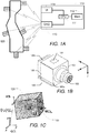
- FIGs. 1A-C schematically illustrate an example of a measurement assembly as disclosed herein.
- FIG. 1A shows a schematic block diagram of a measurement assembly
- FIG. 1B shows a schematic view of a transducer of the measurement assembly
- FIG. 1C illustrates examples of coordinate systems as used for the purpose of the present description.
- the measurement assembly comprises a measurement system 110 and a plurality of triaxial accelerometers 100 attached to a target object 120 and communicatively coupled to the measurement system 110.
- the triaxial accelerometers 100 may for example comprise a triaxial piezoelectric accelerometer of types 4524, 4524-B or 4504 all manufactured by Brüel and Kj ⁇ r Sound and Vibration Measurement, N ⁇ rum, Denmark.
- the skilled person will understand that other types of transducers, e.g. other types of accelerometers, may be used in alternative embodiments.
- other types of single-axis or multiple-axis accelerometers from numerous other manufacturers may of course in the alternative be used to implement the present invention.
- one or more piezoelectric transducer elements 101 may be mounted inside the transducer housing 107, the one or more transducer elements responding to acceleration in a particular direction of three orthogonal spatial directions relative to the accelerometer, (for the purpose of the present description designated i, j, k directions), by producing a sensor signal, e.g. a voltage or current proportional to the acceleration in that particular direction.
- the directions i, j, k thus define a measurement coordinate system of the accelerometer.
- Various types of electronic signal conditioning circuitry and/or memory devices may likewise be mounted inside the transducer housing 107 on a suitable carrier such as low-noise preamplifiers, filters, A/D converters, power supplies etc.
- the electronic signal conditioning circuitry may be coupled to respective output terminals of the one more piezoelectric transducer elements to provide a low-impedance and possibly frequency shaped output signal of the accelerometer 100 for each sensitivity direction.
- the accelerometer housing 107 may comprise a metallic composition or material such as titanium to protect the transducer element(s) against various harmful environmental pollutants e.g. humidity, mechanical shock, dust, light and heat etc.
- the metallic accelerometer housing 107 may also be useful for EMI shielding purposes.
- the accelerometer housing 107 comprises a number of optional slots 109a, 109b which support mounting clips for attachment or fitting of the accelerometer 100 to a number of different target objects.
- a lower substantially plane outer housing surface (hidden from view - arranged oppositely to the outer housing surface 101) of the accelerometer housing 107 is brought directly or indirectly (for example via a suitable adhesive agent or adhesive layer) in physical contact with the target object.
- the lower substantially plane outer housing surface of the accelerometer housing 107 therefore acts a joining or coupling surface to the target object.
- the triaxial accelerometer 100 further comprises an electrical connector 102 which may comprise a 4-pin connector comprising a common ground terminal and three separate output signal terminals carrying the accelerometer i, j, k component output signals, respectively, representing the corresponding first, second and third orthogonal axes of sensitivity of the transducer element(s) of the triaxial accelerometer 100.
- an electrical connector 102 which may comprise a 4-pin connector comprising a common ground terminal and three separate output signal terminals carrying the accelerometer i, j, k component output signals, respectively, representing the corresponding first, second and third orthogonal axes of sensitivity of the transducer element(s) of the triaxial accelerometer 100.
- the i component output signal indicates the acceleration of the accelerometer 100 in the predefined i direction of the accelerometer protruding orthogonally through the first plane outer housing surface 101.
- the target object 120 may, for example, comprise an automotive body, an aircraft structure, a train structure, a wind turbine blade, a satellite structure, an engine, a transmission, etc. or parts thereof.
- the electrical connector 102 may be used for coupling the i, j and k component output signals to the measurement system 110 via a suitable cable, e.g. low-noise shielded cable.
- a suitable cable e.g. low-noise shielded cable.
- a practical measurement set-up may include numerous, e.g. more than 20, or even more than 100, individual triaxial accelerometers 100 coupled to the measurement system via suitable electrical cabling.
- the measurement system 110 may comprise a suitable accelerometer instrumentation system in combination with various types of data acquisition software executed on a personal computer or other computing hardware platform.
- the measurement system may comprise data acquisition interface 113, a data processing unit 111, a memory 112 or other data storage device and a user interface 114.
- the data acquisition interface 113 may include connectors to allow each of the numerous triaxial accelerometers to be coupled to a particular measurement channel of the measurement system.
- the data processing unit 111 may e.g. be a suitably programmed central processing unit of a computer or other data processing system.
- the data processing unit 111 may further be configured to execute a structural analysis software application that performs structural analysis calculations with respect to the target object and based on sensor signals received from the accelerometers 100.
- the user interface 114 may include a display configured for graphically depicting status and identifiers of each of the measurement channels as well as identification and status information of each accelerometer for example by serial number.
- the display may further allow display of a digital 3D model of the target object indicating the determined positions and orientations of the accelerometers.
- the measurement system associates or links the determined spatial 6-dimensional position and orientation data of each of the triaxial accelerometers 100 and, optionally, their serial numbers and or other information pertaining to the respective accelerometers with the particular measurement channels connected to respective ones of the i, j, k output signals of the respective accelerometers (through the 4 pin connectors 102) representing the i, j, k components, respectively, of acceleration of the tri-axial accelerometers 100 on the target object.
- the measurement system may include multiple separate components. The components may be communicatively coupled with each other so as to allow data transfer.
- the measurement system may include a data acquisition system configured to record sensor signals from the transducers and a data processing system configured to analyse the recorded sensor signals.
- the target object 120 may be considered as a rigid body ⁇ that can move unrestrictedly in a 3D space.
- the position and the orientation of the body is defined in the inertial global coordinate system (GCS).
- GCS inertial global coordinate system
- LCS local coordinate system
- FIG. 1C only a single accelerometer is shown explicitly; it will be appreciated that the number N of accelerometers will typically be larger than 1, in particular larger than 3 and often larger than 10 or even larger than 100.
- Each accelerometer 100 measures the proper acceleration relative to the (inertial) GCS; the acceleration vector is provided via its three scalar components measured along the measurement axes of the accelerometer.
- N measurement coordinate systems MCS
- the position and orientation of the MCSs are fixed in LCS.
- r 0 t G x 0 t , y 0 t , z 0 t G T is the radius vector of LCS's origin and ⁇ 1 ( t ); ⁇ 2 ( t ); ⁇ 3 ( t ) are three Euler angles, defining the consecutive rotations that bring the GCS to the LCS.
- ⁇ r ⁇ L can be obtained as three consecutive rotations, first around z axis of GCS by ⁇ 1 , then about the new y axis by ⁇ 2 and finally about the new x axis by ⁇ 3 :
- r L 1 0 0 0 cos ⁇ 3 sin ⁇ 3 0 ⁇ sin ⁇ 3 cos ⁇ 3 cos ⁇ 2 0 ⁇ sin ⁇ 2 0 1 0 sin ⁇ 2 0 cos ⁇ 2 cos ⁇ 1 sin ⁇ 1 0 ⁇ sin ⁇ 1 cos ⁇ 1 0 0 0 1
- rotation matrices are orthogonal matrices.
- R LM , n c 1 , n c 2 , n c 2 , n s 1 , n ⁇ s 2 , n ⁇ c 3 , n s 1 , n + c 1 , n s 2 , n s 3 , n c 1 , n c 3 , n + s 1 , n s 2 , n s 3 , n c 2 , n s 3 , n c 1 , n c 3 , n c 1 , n c 3 , n s 2 , n + s 1 , n s 3 , n c 3 , n s 2 , n + s 1 , n s 3 , n c 3 , n s 1 , n c 3 , n s 2 , n + s 1 , n s 3 , n
- y 0 t ⁇ y 0 t
- z 0 t ⁇ z 0 t
- ⁇ 1 t ⁇ 1 t
- ⁇ 2 t ⁇ 2 t
- ⁇ 3 t ⁇ 3 t
- ⁇ is used as a book-keeping device to indicate the order of magnitude of the attached terms.
- the signals measured by the n-th triaxial accelerometer can be approximated as a product of the matrix [ ⁇ n ] and vector ⁇ C ( t ) ⁇ , differentiated twice w.r.t.
- the measured acceleration by an accelerator may be computed from the transducer transmissibility matrix associated with said transducer and from the spatial configuration, differentiated twice with respect to time, of a local coordinate system of the target object.
- the transducer transmissibility matrix represents the spatial configuration of the measurement coordinate system of said accelerometer relative to the local coordinate system of the target object.
- FIG. 2 illustrates a flow diagram of an example of a measurement process disclosed herein.
- the measurement process may e.g. be performed using an assembly as described in connection with FIGs. 1A-C .
- the target object on which structural analysis is to be performed e.g. object 120 shown in FIGs. 1A and 1C
- the type of mounting may depend on the characteristics of the target object, such as its volume, mass and structural integrity and on the objectives of the measurements to be taken, e.g. the type of structural analysis to be performed.
- the target object is mounted on rubber bungees and/or air pillows, its rigid body motion in any direction remains substantially unrestricted.
- a mounting that partly restricts the rigid body motion of the target object may be desirable.
- a plurality of transducers such as accelerometers, e.g. triaxial accelerometers as shown in FIG. 1B , are mounted to the target object such that they can record movements of the target object.
- the transducers may be distributed across and attached to the surface of the target object, e.g. by suitable mounting elements, an adhesive or the like.
- the transducers are mounted such that the spatial configurations, i.e. the positions and orientations, of a first subset of the transducers relative to the target object are known or manually determined, e.g. measured.
- the transducers of the first subset may be positioned at easily recognisable positions of the target object and aligned with easily recognisable directional features of the target objects, e.g. at respective edges, corners, or similar surface features.
- the positions of the reference transducers may be provided as their coordinates w.r.t. the LCS.
- the orientations of the reference transducers relative to the LCS may be provided using any suitable convention for defining orientations. For example, they may be provided as three Tait-Bryan angles following z-y'-x" convention. The angles correspond to consecutive rotations from LCS to MCSs of the reference transducers.
- the reference transducers may be position such that the area surrounded by the reference transducers covers most of the target object.
- only information about spatial relationships between the reference transducers e.g. their mutual distances from each other may need to be entered rather than their complete spatial configurations.
- the first subset preferably comprises at least three triaxal accelerometers which are not positioned along a straight line.
- the accelerometers of the first subset will also be referred to as reference accelerometers.
- step S30 the measurement system, e.g. measurement system 110 of the embodiment of FIG. 1 , is initialised.
- the transducers are communicatively connected to the data acquisition interface of the measurement system.
- the known spatial configurations of the reference transducers (or at least information about their spatial relationships) may be entered into the measurement system.
- a digital model of the target object e.g. a CAD model and FE model or the like, may be loaded into a memory of the measurement system.
- one or more operational parameters of the signal processing to be performed by the measurement system may be set, e.g. adjustable attenuations, filter parameters and/or the like.
- a value of a high-pass filter to be applied to the acquired sensor signals may initially be set to a small value, e.g. less than 1 Hz, such as 0.7Hz. It will be appreciated that suitable values may depend on the specific data acquisition system and/or the characteristics of the target object to be tested.
- some of the parameters may be set based on initial measurements.
- the target object may be excited, e.g. using a modal hammer, a hammer-like object, or in another suitable manner.
- the measurement system may acquire sensor signals from the transducers responsive to the excitation, e.g. in response to the impact of the modal hammer or hammer-like object. This step may be repeated for multiple excitations, e.g. at respective excitation points.
- the process may compute a frequency spectrum or frequency response function for all transducers and estimate the natural frequency of the lowest flexural mode and the natural frequency of the highest rigid body mode. The process may then estimate the cut-off frequency of a low-pass-filter to be applied to the subsequent sensor signals for the purpose of determining the spatial configurations of the transducers.
- the cut-off frequency may be selected such that the low-pass-filer will keep the information regarding rigid body motion but exclude the flexural motion of the target object.
- the data acquisition part of the measurement system may then be configured to conduct recordings with a sampling frequency that is greater than a predetermined threshold.
- the threshold may be selected depending on the determined cut-off frequency of the low-pass filter, e.g. 2.56 times the cut-off frequency of the low-pass filter.
- step S40 the process acquires sensor signals from the transducers.
- movement of the target object in particular rigid body movement, may be induced and sensor signals responsive to the induced movement may be acquired.
- the data acquisition may be initiated and the target object may be caused to swing in such a manner that it experiences all 6 degrees of freedom (3 translatory and 3 rotational degrees of freedom).
- This may be done manually, e.g. by swinging the suspended object by hand or by using a heavy hammer with very soft tip.
- the resonant frequency of the rigid body modes is typically very low, it might be difficult to excite the rigid body modes to have sufficient signal to noise ratio in the acceleration signals. Therefore, it may be advantageous to record sufficient data based on multiple swings in each of the 6 degrees of freedom, e.g. based on at least 20-40 swings in each of the 6 directions.
- the acquired sensor signals may be represented as a time series of measurements. In some embodiments, where only spatial relationships of the transducers of the first subset have initially been entered, this step may be followed by a computation of the complete spatial configurations of the transducers of the first set.
- the process computes the spatial configurations of the transducers other than the reference transducers from the known spatial configurations of the reference transducers and from the acquired sensor signals.
- An example of a computational process for computing the spatial configurations of the transducers will be described in detail below with reference to FIG. 3 .
- the process may detect to what extent the acquired data is suitable or sufficient to compute the spatial configurations of all transducers with a desired accuracy. The process may alert the user if such computation is not possible. The user may then repeat the data acquisition, e.g. by acquiring more data so as to improve the signal-to-noise ratio, by re-adjusting some of the parameters, e.g. the cut-off frequency of the low-pass filter, or by moving the accelerometers to other locations (keeping the reference accelerometers in place) and repeating the measurements.
- step S60 additional data may be acquired in step S60.
- the target object may be moved so as to excite both flexural and rigid body modes and further sensor signals from all transducers may be acquired.
- the previous low-pass filtering to suppress flexural modes may be omitted.
- the process may perform the desired structural analysis computations based on the acquired additional data and based on the known and determined spatial configurations of all transducers.
- structural analysis is intended to encompass any computational method based on the recorded transducer signal that results in information about the behaviour of the target object when subjected to force and, in particular subject to dynamic loading.
- Examples of structural analysis may include an analysis of dynamic displacements, time history, and modal analysis, vibrational analysis, etc.
- the structural analysis may include a finite element analysis, e.g. so as to calculate mode shapes and frequencies.
- FIG. 3 illustrates a flow diagram of an example of a computer-implemented process for determining the spatial configurations of transducers, in particular of triaxial accelerometers, as disclosed herein.
- the process may e.g. be performed by the measurement system 110 as described in connection with FIG. 1A .
- the process receives the input data.
- the process receives the positions and orientations of the respective reference accelerometers.
- the positions may be received as the coordinates of the reference accelerometers w.r.t. the LCS.
- the orientation of each reference accelerometer may be received as three Tait-Bryan angles following z-y'-x" convention. The angles correspond to consecutive rotations from LCS to MCSs of the reference accelerometers.
- the positions and orientations may have been entered manually, determined by another automated procedure or computed based on entered information of spatial relationships between the reference transducers and based on the sensor signals.
- the process further receives the sensor signals of all accelerometers that have been recorded in response to an induced motion of the target object, e.g. the recordings acquired in step S40 of the process of FIG. 2 .
- the process may further receive a channel table of the data acquisition interface to which the accelerometers are connected during measurement, and an indication as to which channels correspond to the reference accelerometers, i.e. which channels correspond to the accelerometers of the first subset and which channels correspond to the accelerometers of the second subset.
- the process may further receive additional information, such as the cut-off frequency of the low-pass filter as described in connection with step S30 of the process of FIG. 2 .
- the process computes the spatial configurations of the accelerometers of the second subset.
- the first subset of transducers comprises R reference accelerometers from a set , which we call a reference set.
- the positions and orientations of all accelerometers of the reference set are known.
- R will also be referred to as transducer transmissibility matrix;
- the transducer transmissibility matrices for the reference accelerometers are known from (13).
- Each transducer transmissibility matrix associates the sensor signal of the corresponding transducer to the vector of second derivatives of positions and orientations (i.e. of accelerations) of a rigid body representing the target object (i.e. of the local coordinates system LCS associated with the target object).
- the accelerometer signals ⁇ a r ( t ) ⁇ are available for the reference accelerometers.
- vector ⁇ C ⁇ ( t ) ⁇ can be estimated as a least squared average of the measured accelerations:
- C ⁇ t B R ⁇ a 1 t ... a R t here symbol ⁇ denotes matrix pseudo-inverse.
- matrix [ ⁇ q ] is a function of r q,x ,r q,y , r q,z , ⁇ q, 1 , ⁇ q, 2 , ⁇ q, 3 and the analytical (nonlinear) expressions are available for each element of this 3x6 matrix.
- Equating element-wise ⁇ q r q , x r q , y r q , z ⁇ q , 1 ⁇ q , 2 ⁇ q , 3 ⁇ ⁇ q one can solve 18 nonlinear equations for 6 unknowns.
- the position of the accelerometer shall not be outside the target object, and the Euler angles are typically subjected to 0 ⁇ ⁇ q , 1 ⁇ 2 ⁇ , 0 ⁇ ⁇ q , 2 ⁇ ⁇ , 0 ⁇ ⁇ q , 3 ⁇ 2 ⁇ .
- approach 1 may be used to compute an initial estimate while approach 2 may be used to refine the approach 1 output.
- the above methodology makes a number of assumptions.
- the above methodology assumes that the target object moves as a rigid body, that the displacements of the induced movement are small, and that the target object moves in all six degrees of freedom.
- the target object does not move as an ideal unrestricted rigid body.
- a target object is supported by e.g. soft bungees and/or air pillows in order to model the object's dynamics in free-free conditions.
- EMA experimental modal analysis
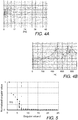
- the choice of the supports' stiffness may be based on the best separation of the rigid body modes' frequencies (defined by the inertia properties of the objects and the stiffness of the supports) and the flexible mode resonances (which depend on the stiffness of the object); a sample frequency response function (FRF) or accelerometer autospectra can be used to check this, e.g. as illustrated by FIGs.
- FPF sample frequency response function
- accelerometer autospectra can be used to check this, e.g. as illustrated by FIGs.
- FIG. 4A shows the FRF of a target object in the frequency range between 0 - 900Hz while FIG. 4B shows an enlarged view of the FRF in the frequency range 0 - 50 Hz.
- the lowest flexural modes occur at about 462 HZ while the highest rigid body modes occur at around 6.5 HZ.
- a good separation between the flexural modes and the rigid modes is indeed possible. Accordingly, by applying a low-pass filter and setting its cut-off frequency above the highest rigid body mode and below the lowest flexible mode, one can significantly attenuate the flexible components of the response and fulfil the assumption for rigid-body motion.
- the target object should experience the motion in all six degrees of freedom, and a special attention should be paid to exciting the target object in such a way that it experiences motion in all six directions, during the data acquisition. It is possible to check how this assumption is fulfilled by checking the singular values of a R t i after applying the low pass filter, which will be discussed below.
- the inventors have found it sufficient in order to excite the target object when the target object is moved by hand in all six directions or excite it with a relatively heavy hammer with a soft tip.
- a relatively heavy hammer with a soft tip.
- it has been found helpful to impact the object at many points in random directions. In this way, the structure will experience oscillations about its initial position, which is believed to be a very useful way to fulfil this assumption.
- step S52 the process performs low pass filtering of the received sensor signals using the determined cut-off frequency.
- step S53 the process verifies whether the induced movements of the target object may be represented as rigid body motions and whether motion occurs in all six degrees of freedom. To this end, the process may compute the singular values of [ a ( t i )] in respect of all accelerometers signals and determine whether the difference and/or ratio between singular values #6 and #7 is larger than a predetermined threshold.
- FIG. 5 shows examples of normalized singular values determined for an example movement of a target object. The gap between singular values #6 and #7 is indicated by arrow 551.
- step S54 the process proceeds at step S54. Otherwise the process returns with a suitable error message, e.g. instructing the user to repeat the step of inducing a movement (e.g. to return to step S40 of the process of FIG. 2 ).
- a suitable error message e.g. instructing the user to repeat the step of inducing a movement (e.g. to return to step S40 of the process of FIG. 2 ).
- the process removes the data corresponding to singular values greater than 6 (e.g. by performing a singular value decomposition followed by a truncation), scales the coordinates such that the biggest distance between references is 1 and computes the matrix [ ] using expression (16).
- the process compares the condition number of the computed matrix [ ] with a predetermined threshold. If the condition number is larger than the threshold, the process returns with a suitable message instructing the user to select a different placement of the reference accelerometers, namely a placement more displaced from a straight line (e.g. to return to step S20 of the process of FIG. 2 ), and to repeat the data acquisition. Otherwise, the process proceeds at step S56.
- the process computes the accelerations of the local coordinate system of the target object using expression (17), i.e. the process computes [ C ⁇ ( t )].
- this step may include computing a least-squares solution of a system of linear equations.
- the process computes the spatial configuration of each of the accelerometers of the second subset i.e. the position and orientation of each non-reference accelerometer.
- An example of a methodology for computing the spatial configuration of an accelerometer of the second subset will be described in more detail below with reference to FIG. 7 .
- step S58 all coordinates are re-scaled back to the original scaling.
- the process stores the determined spatial configurations for use during subsequent measurements.
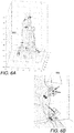
- the process may also present the results to the user, for example via a graphical user interface, e.g. as illustrated in FIGs. 6A-B.
- FIG. 6A schematically illustrates a displayed 3D digital model of a target object indicating the determined spatial configurations of respective accelerometers.
- FIG. 6B shows an enlarged view of a part of the displayed 3D digital model.
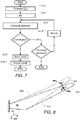
- FIG. 7 illustrates a flow diagram of an example of a computer-implemented process for determining the spatial configurations of a transducer of the second subset, in particular of triaxial accelerometers, as disclosed herein.
- the process may e.g. be performed by the measurement system 110 as described in connection with FIG. 1A .
- initial step S571 the process computes the transmissibility matrix [ ⁇ q ] using expression (21).
- step S572 the process computes a starting point, e.g. as the average of the positions of the reference accelerometers.
- step S573 the process computes an initial estimate of the unknown position and orientation, e.g. using Newton's method.
- step S575 If the Newton method converges, the process proceeds at step S575; otherwise, if the method does not converge, the process proceeds to step S574 where the process adds a random displacement to the starting point and returns to step S573. If the algorithm does not converge after a predetermined number of attempts (e.g. after 5-10 attempts), the process marks the current accelerator with an error and proceeds to the next accelerometer. The accelerometers marked with an error may have to be repositioned or their positions may have to be determined manually.
- step S575 the process stores the computed position and orientation for the current accelerometer.
- the additional minimization step may use the result of the Newton's method as a starting point, generate a set of constraints, e.g. using expression (29), and run a minimization algorithm minimizing a suitable objective function, e.g. as defined in expression (28).
- the minimization is subject to linear constraints.
- the minimization may be performed by any suitable routine, e.g. using MATLAB's FMINCON. This routine automatically selects the optimization method, depending on the type of the function and the constraints. For this particular optimization problem, there is no need to provide the Jacobian and Hessian (the first and the second derivative w.r.t.
- the process may store the optimization result as a final estimate of the position and orientation.
- the process may further store a quality indicator of the result, e.g. the relative error of the fit.
- the method outputs their positions and orientations in the LCS attached to one of them.
- the output of the method can be considered as the input to the previously described method, thus the position and orientation of all other accelerometers can be obtained, based on the same dataset.
- test set signals can be estimated from the reference set signals as where the matrix can be interpreted as a transmissibility matrix between the signals from the reference set and the signals from the test set.
- the difference between the predicted j -th signal from the test set and the corresponding measured signal is
- the constraints in (40) are geometrical constraints - not allowing the accelerometers positions to be sought outside the target object dimensions and the constraints on Euler angles, (29).
- the inventors believe that the product is invariant to the linear scale, i.e. if all linear dimensions in ⁇ ⁇ and ⁇ ⁇ are multiplied by a same scalar, the resulting matrix product is the same. Intuitively, it could be understood as using different linear units when measuring the linear distances, e.g. inches or millimeters. This means that the solution will contain distances up to a multiplier; in case of using minimization, the minimization routine will have difficulties in convergence. One way to avoid this is to introduce extra constraints, for example providing the optimization routine with the distances between the three accelerometers, , and .
- the reference set consists of a combination of six signals from all the three accelerometers.
- a convenient (but not obligatory) way is to compose it from all three signals of the accelerometer , one or two signals from and the rest from , for example, a possible reference set could be where the subscript indicates the measurement direction of the given accelerometer. Then the test set should include the remaining signals, namely The strategy for selecting the optimal signals will be discussed later.
- the objective function in (40) is a strongly nonlinear function of its 12 parameters, with the optimization problem subjected to nonlinear constraints (41). In some situations, the convergence of the optimization problem may be sensitive to the selection of a good starting point.
- the accuracy of the results may be increased, e.g. in situations where the accelerometers are not perfectly aligned with the direction of gravity.
- the optimization problem (40) seeks a minimum of a real scalar positive objective function , which is a strongly nonlinear function of 12 variables (8 variables for the relaxed case), and periodic on some of them.
- the minimization is subjected to a set of nonlinear constraints (41).
- MATLAB's FMINCON which is a part of MATLAB's Optimization Toolbox, is a convenient routine to solve the minimization problem.
- FMINCON requires providing the sensitivity of the objective function and the constraints w.r.t. the variables. It requires both first order derivative (Jacobian) and the second order sensitivities (Hessian) of the objective function and the constraints.
- FMINCON can compute the derivatives automatically, using finite difference. However, it may be preferable to provide analytic (exact) sensitivities whenever possible. The derivation of sensitivities is explained in the following.
- the objective function (39) is a function of either 8 or 12 variables, depending on if the relaxed or not-relaxed formulation is considered. If all variables are combined into a single vector the Jacobian of the objective function is a vector ⁇ ⁇ whose i -th element is From the definition of the objective function (39), Utilizing (35)-(38), where the difference between the predicted and measured signal is using the sampled representation of signals: ⁇ a r ( t ) ⁇ ⁇ [ a r ( t i )], and [ a r ( t i )] ⁇ R 6 ⁇ M .
- the subscript j after ⁇ or [] brackets denotes the j -th element of the vector or the j -th row of the matrix, respectively.
- the derivative of the [ ] matrix is rather straightforward, the derivative of the inverse is more involving: Combining all the above-mentioned and substituting into (45), one can get analytical expression for the Jacobian (except the matrix inverse, which is more convenient to compute using numerical methods).
- the Hessian is a square matrix whose elements are
- Hessian The elements of Hessian can be computed using the same considerations as for Jacobian.
- constraints (41) can be reformulated as where the estimates of the squared distances for the given variables values ⁇ ⁇ are and the gradients of the constraints (54) are quite straightforward.
- the constraints gradients is a 3x8 or 3x12 matrix; as an example, few elements are provided below.
- the derivatives w.r.t. Euler angles are zeros.
- the embodiments of the method described above assume that the target object is rigid and its motion is unconstrained.
- an embodiment will be described which can be applied to flexible target objects whose motion can be constrained.
- such objects represent a significant fraction of target objects, where the presented methodology can be helpful. Examples include a wind turbine blade mounted on a test rig, civil structures like bridges, towers, chimneys, and alike.
- FIG. 8 illustrates an example of a deformable target object whose motion is constrained, the latter being described by some boundary conditions.
- each point P of the target object has coordinates described by the radius vector, which in GCS is ⁇ r ⁇ G ⁇ ⁇ , where ⁇ is the domain where the target object is defined.
- the displacement of the point P is defined by the vector ⁇ d ( ⁇ r ⁇ G ,t ) ⁇ G .
- the subscripts denoting GCS are omitted.
- a triaxial accelerometer 811 is mounted on the object at point P n with coordinates in GCS ⁇ r n ⁇ ⁇ ⁇ , and its orientation is such that its MCS can be obtained from the GCS by the rotation matrix [ R GM , n ].
- ⁇ is a set of time-independent vectors that satisfy boundary conditions (so-called, essential boundary conditions) and are mutually-orthogonal.
- D k ( t ) are time-dependent scalars.
- One of the convenient (but not necessary) choises of ⁇ k ( ⁇ r ⁇ ) ⁇ are the mode shapes of the object, then D k ( t ) are so-called modal coordinates.
- (62) can be presented as where the first sum significantly contributes to the overall displacement of the target object and the latter does not, and can be neglected.
- a k ( t ) D ⁇ k ( t ).
- Substituting (64) into (61) yields
- E x v q 2 1 M ⁇ x t i v q T ⁇ x t i v q
- E y v q 2 1 M ⁇ y t i v q T ⁇ y t i v q
- E z v q 2 1 M ⁇ z t i v q T ⁇ z t i v q
- the left-hand-sides of the expressions (80) are positive scalar functions of the vector of variables ⁇ v q ⁇ , which can be combined into a positive scalar function
- E v q 2 E x v q 2 + E y v q 2 + E z v q 2 .
- the minimization problem can be formulated as: min v E v q 2 subject to v min ⁇ v q ⁇ v max
- the latter presents the possible constraints, for example the position of the accelerometer shall not be outside the target object ( ⁇ r n,x ,r n,y ,r n,z ⁇ T ⁇ ⁇ ), and the Euler angles are typically subjected to 0 ⁇ ⁇ q , 1 ⁇ 2 ⁇ , 0 ⁇ ⁇ q , 2 ⁇ ⁇ , 0 ⁇ ⁇ q , 3 ⁇ 2 ⁇ .
- the embodiment presented above demonstrates how the methodology for finding positions / orientations of accelerometers can be applied to deformable target objects, whose motion is constrained by some (sufficiently rigid) supports.
- target objects are include many objects tested "in situ", which are typically big civil structures, e.g. wind turbines, towers, bridges, etc.
- the method assumes that one can find a set of spatial functions ⁇ k ( ⁇ r ⁇ ) ⁇ , r ⁇ ⁇ which (i) satisfy essential boundary conditions of the target object and (ii) mutually orthogonal.
- the best set of such functions is a set mode shapes, known e.g. from FE analysis of the target object. Any other set satisfying the abovementioned conditions is valid, however they may require more shapes to be taken into account, and consequently, need more reference accelerometers.
- the method comprises:
- FIG. 9 shows different views of an example of a target object having transducers mounted thereon.
- a transmission housing 901 was supported by rubber bands 902 as shown in FIG. 9 .
- Three accelerometers 903 type 4506 B available from Brüel & Kj ⁇ r Sound & Vibration Measurement A/S, N ⁇ rum, Denmark were selected as reference accelerometers and mounted as shown in FIG. 9 .
- spirit level UA-140 and swivel bases UA-1473 both available from Brüel & Kj ⁇ r Sound & Vibration Measurement A/S, N ⁇ rum, Denmark, the accelerometers were aligned so their Y axes were vertical and pointing upwards.
- the coordinates of the reference accelerometers were measured using BIG FP5500 3D Creator, available from Boulder Innovation Group, Inc., Boulder, CO, USA, with a sub-millimeter precision:
- the main features of the structure were digitized point by point by BIG FP5500 3D Creator using an ATC software that provided highly precise wireframe model.
- the transmission housing was also digitized using the Sony 3D Creator app running on a Sony Xperia XZ1 mobile phone, which was exported to MATLAB via a Wavefront OBJ file.
- the latter representation consists of nodes and triangular faces.
- FIG. 10A shows a histogram of positioning errors.
- the histogram is based on the non-reference accelerometers.
- An example of sensor localizations is shown in FIGs 6A-B .
- FIG. 6A shows a view of the digitized 3D model of the transmission housing 901 where the determined positions and orientations of the accelerometers are shown for example setup #2.
- FIG. 6B an enlarged portion of the transmission housing an two accelerometer positions are shown including the known locations of the accelerometers which are indicated by black dots.
- the localization error is estimated as the distance between the black dot (obtained with 3D Creator) and a second dot, which is the projection of the estimated accelerometer centre to the mounting surface, as indicated in FIG. 6B by red arrows.
- FIG. 10B shows a histogram of orientation errors. For each setup, there were 5 test accelerometers, thus 5 orts per direction. For each pair of orts, the angle between them was computed (as arccos of orts' scalar product); this resulted in 10 angles per direction, i.e. 30 angles for three directions. For the three Setups (#4,5,6), the statistics is:
- Embodiments of the method described herein may be employed during a test setup, in particular for the determination of the positions and orientations of transducers on a target object.
- Embodiments of the method described herein may also be employed in order to verify the mounting of accelerometers, e.g. so as to verify that the position / orientation of the accelerometers has not changed during the test.
- embodiments of the method described herein may also be employed in order to create a digital representation, e.g. a digital 3D model, of a simplified geometry of the target object.
- a digital representation e.g. a digital 3D model
- it is convenient to make a simplified geometry of the target object e.g. so as to visualize the obtained frequency response functions or mode shapes.
- the suggested technique allows a determination of the accelerometers' positions it can be used for a quick and rough "digitizing" of the target object, by connecting obtained nodes, where the accelerometers are placed, with lines.
- Embodiments of the method described herein can be implemented by means of hardware comprising several distinct elements, and/or at least in part by means of a suitably programmed microprocessor.
- several of these means can be embodied by one and the same element, component or item of hardware.
- the mere fact that certain measures are recited in mutually different dependent claims or described in different embodiments does not indicate that a combination of these measures cannot be used to advantage.
Landscapes
- Engineering & Computer Science (AREA)
- Theoretical Computer Science (AREA)
- General Engineering & Computer Science (AREA)
- General Physics & Mathematics (AREA)
- Physics & Mathematics (AREA)
- Health & Medical Sciences (AREA)
- Human Computer Interaction (AREA)
- Computing Systems (AREA)
- General Health & Medical Sciences (AREA)
- Medical Informatics (AREA)
- Computer Networks & Wireless Communication (AREA)
- Signal Processing (AREA)
- Length Measuring Devices With Unspecified Measuring Means (AREA)
- Measurement Of The Respiration, Hearing Ability, Form, And Blood Characteristics Of Living Organisms (AREA)
Claims (18)
- Computerimplementiertes Verfahren eines Bestimmens von jeweiligen räumlichen Konfigurationen, die indikativ sind für jeweilige Positionen und Ausrichtungen, einer Mehrzahl von Transducern (100, 903, 904), die an einem Zielobjekt (120, 901) angebracht sind; wobei das Verfahren umfasst:- Empfangen (S40) von Sensorsignalen von jeder der Mehrzahl von Transducern, wobei die Sensorsignale indikativ sind für jeweilige Bewegungen der jeweiligen Transducer während einer induzierten Bewegung des Zielobjekts;- Bestimmen (S30, S50) der räumlichen Konfigurationen der Mehrzahl von Transducern; wobei die räumlichen Konfigurationen, die indikativ sind für die Positionen und Ausrichtungen relativ zum Zielobjekt, von zumindest einer Untermenge der Transducer auf Basis der empfangenen Sensorsignale bestimmt werden;wobei die Mehrzahl von Transducern eine erste Untermenge von Transducern (903) und eine zweite Untermenge von Transducern (904) umfasst; wobei Bestimmen der räumlichen Konfigurationen der Mehrzahl von Transducern umfasst:- Erhalten (S30) von räumlichen Konfigurationen der Transducer der ersten Untermenge; und- Bestimmen (S50) der räumlichen Konfigurationen der Transducer der zweiten Untermenge von den empfangenen Sensorsignalen und von den erhaltenen räumlichen Konfigurationen der Transducer der ersten Untermenge;und wobei Bestimmen von räumlichen Konfigurationen der Transducer der zweiten Untermenge umfasst:- Berechnen (S56), aus den empfangenen Sensorsignalen der Transducer der ersten Untermenge und den empfangenen räumlichen Konfigurationen, von Objektbeschleunigungen, die indikativ sind für Beschleunigungen des Zielobjekts relativ zu einem Referenzkoordinatensystem;- Berechnen (S57), aus den berechneten Objektbeschleunigungen und aus den empfangenen Sensorsignalen von jeweiligen Transducern der zweiten Untermenge, der räumlichen Konfigurationen der Transducer der zweiten Untermenge.
- Verfahren nach Anspruch 1; wobei die Transducer jeweilige Beschleunigungsmesser, insbesondere triaxiale Beschleunigungsmesser umfassen.
- Verfahren nach einem der vorherigen Ansprüche; umfassend Empfangen von Informationen, die nur einen Teil der räumlichen Konfigurationen der Mehrzahl von Transducern darstellen, als eine Eingabe; und wobei Bestimmen der räumlichen Konfigurationen der Mehrzahl von Transducern Bestimmen eines verbleibenden Teils der räumlichen Konfigurationen umfasst, um die vollständigen räumlichen Konfigurationen sämtlicher Transducer der Mehrzahl von Transducern zu bilden.
- Verfahren nach einem der vorherigen Ansprüche; wobei die erste Untermenge drei triaxiale Beschleunigungsmesser umfasst.
- Verfahren nach einem der Ansprüche 1 bis 4, wobei erste Untermenge eine Mehrzahl von Transducern umfasst, die ausreichend sind, um translatorische Bewegung des Zielobjekts entlang dreier orthogonaler Richtungen und rotatorische Bewegung um drei orthogonale Achsen zu messen.
- Verfahren nach Anspruch 5; umfassend Überprüfen, ob die erste Untermenge eine ausreichende Anzahl von Transducern einschließt.
- Verfahren nach Anspruch 6; wobei die Transducer jeweilige triaxiale Beschleunigungsmesser umfassen, und wobei Überprüfen Überprüfen umfasst, ob eine Transformationsmatrix, die aus jeweiligen Transducer-Transformationsmatrizen der Transducer der ersten Untermenge konstruiert ist, vollen Rang hat; wobei jede Transducer-Transformationsmatrix eine Transformation zwischen Beschleunigungen des jeweiligen Transducers relativ zu einem lokalen Koordinatensystem des Zielobjekts in Beschleunigungen darstellt, die vom Transducer gemessen werden, entlang der Achsen eines Messkoordinatensystems des Transducers.
- Verfahren nach einem der Ansprüche 1 bis 7; umfassend Bestimmen (S53), ob die induzierte Bewegung ausreichend ist zum Bestimmen der räumlichen Konfigurationen der Transducer der zweiten Untermenge von Transducern.
- Verfahren nach Anspruch 8; wobei die Transducer jeweilige triaxiale Beschleunigungsmesser umfassen; wobei die empfangenen Sensorsignale indikativ sind für gemessene Beschleunigungen der Transducer während der induzierten Bewegung; und wobei Bestimmen, ob die hervorgerufene Bewegung ausreichend zum Bestimmen der räumlichen Konfigurationen der Transducer der zweiten Untermenge ist, umfasst:- optional Durchführen einer Tiefpassfilterung der Sensorsignale;- Bestimmen, ob eine lokale Beschleunigungsmatrix, die die gemessenen Beschleunigungen darstellt, eine vorbestimmte Anzahl von dominanten Singulärwerten hat.
- Verfahren nach einem der Ansprüche 1 bis 9; wobei Erhalten der räumlichen Konfigurationen der Transducer der ersten Untermenge umfasst:- Empfangen Informationen, die indikativ sind für eine Menge von räumlichen Verhältnissen zwischen den Transducern der ersten Untermenge;- Berechnen, aus den empfangenen Konfigurationen und aus den empfangenen Sensorsignalen, der räumlichen Konfigurationen der Transducer der ersten Untermenge.
- Verfahren nach einem der Ansprüche 1 bis 10; wobei das Zielobjekt ein verformbares Objekt (810) ist, dessen Bewegung von einer Objekthalterung beschränkt ist; und wobei das Verfahren umfasst:- Berechnen von zeitabhängigen Beschleunigungskoeffizienten des Zielobjekts aus den räumlichen Konfigurationen der Transducer der ersten Untermenge und aus den empfangenen Sensorsignalen.- Berechnen, aus den berechneten zeitabhängigen Beschleunigungskoeffizienten und aus den empfangenen Sensorsignalen, der räumlichen Konfiguration der Transducer der zweiten Untermenge.
- Verfahren nach einem der vorherigen Ansprüche; umfassend Filtern der aufgezeichneten Signale, um Frequenzen zu unterdrücken, die zu Biegemoden der induzierten Bewegungen gehören.
- Verfahren nach einem der vorherigen Ansprüche; wobei Berechnen der Objektbeschleunigungen Berechnen einer Lösung der kleinsten Quadrate zu einem System von linearen Gleichungen umfasst, wobei jede lineare Gleichung eine Transformation zwischen gemessenen Beschleunigungen, gemessen mittels eines der Referenz-Beschleunigungsmesser, und unbekannten Objektbeschleunigungen darstellt.
- Computerimplementierter Messprozess, umfassend:- Bestimmen von räumlichen Konfigurationen einer Mehrzahl von Transducern, die an einem Zielobjekt angebracht sind, indem die Schritte des Verfahrens nach einem der Ansprüche 1 bis 13 durchgeführt werden;- Empfangen (S60) von weiteren Sensorsignalen von der Mehrzahl von Transducern, wobei die empfangenen weiteren Sensorsignale indikativ sind für jeweilige Bewegungen der jeweiligen Transducer während einer induzierten Bewegung des Zielobjekts;- Durchführen (S70) von Strukturanalyse-Berechnungen auf Basis der empfangenen weiteren Sensorsignale.
- Datenverarbeitungssystem, konfiguriert zum Durchführen der Schritte des Verfahrens nach einem der Ansprüche 1 bis 13.
- Computerprogramm, konfiguriert zum Veranlassen eines Datenverarbeitungssystems zum Durchführen der Schritte des Verfahrens nach einem der Ansprüche 1 bis 13, wenn das Computerprogramm von dem Datenverarbeitungssystem ausgeführt wird.
- Messsystem (110), umfassend:- ein Datenverarbeitungssystem nach Anspruch 15:- eine Mehrzahl von Eingangskanälen, konfiguriert, um über jeweilige drahtlose oder drahtgebundene Signalverbindungen, mit jeweiligen Transducer-Ausgangssignalen einer Mehrzahl von Transducern gekoppelt zu werden, die an einem Zielobjekt angebracht sind;- eine Dateneingabeschnittstelle, konfiguriert zum Empfang von jeweiligen räumlichen Koordinatendaten der Transducer der ersten Untermenge, beispielsweise mittels manueller Dateneingabe oder von einer anderen Einrichtung über eine drahtlose oder drahtgebundene Kommunikationsverbindung.
- Transduceranordnung, umfassend:- ein Messsystem (110) nach Anspruch 17; und- eine Mehrzahl von Transducern (100), die an einer Mehrzahl von vorbestimmten Messorten montierbar sind, die über ein Zielobjekt verteilt sind.
Priority Applications (7)
| Application Number | Priority Date | Filing Date | Title |
|---|---|---|---|
| SI201830158T SI3572819T1 (sl) | 2018-05-25 | 2018-05-25 | Postopek za določanje prostorskih konfiguracij množice pretvornikov glede na ciljni predmet |
| EP18174296.6A EP3572819B1 (de) | 2018-05-25 | 2018-05-25 | Verfahren zur bestimmung räumlicher konfigurationen von einer vielzahl von wandlern in bezug auf ein zielobjekt |
| DK18174296.6T DK3572819T3 (da) | 2018-05-25 | 2018-05-25 | Fremgangsmåde til bestemmelse af rumlige konfigurationer af en flerhed af transducere i forhold til en målgenstand |
| CN201980035059.5A CN112771385B (zh) | 2018-05-25 | 2019-05-22 | 确定多个换能器相对于目标物体的空间配置的方法 |
| US17/250,098 US11150747B2 (en) | 2018-05-25 | 2019-05-22 | Method of determining spatial configurations of a plurality of transducers relative to a target object |
| PCT/EP2019/063264 WO2019224277A1 (en) | 2018-05-25 | 2019-05-22 | Method of determining spatial configurations of a plurality of transducers relative to a target object |
| JP2020565418A JP7346462B2 (ja) | 2018-05-25 | 2019-05-22 | ターゲット物体との関係において複数のトランスデューサの空間的構成を決定する方法 |
Applications Claiming Priority (1)
| Application Number | Priority Date | Filing Date | Title |
|---|---|---|---|
| EP18174296.6A EP3572819B1 (de) | 2018-05-25 | 2018-05-25 | Verfahren zur bestimmung räumlicher konfigurationen von einer vielzahl von wandlern in bezug auf ein zielobjekt |
Publications (2)
| Publication Number | Publication Date |
|---|---|
| EP3572819A1 EP3572819A1 (de) | 2019-11-27 |
| EP3572819B1 true EP3572819B1 (de) | 2020-09-09 |
Family
ID=62386108
Family Applications (1)
| Application Number | Title | Priority Date | Filing Date |
|---|---|---|---|
| EP18174296.6A Active EP3572819B1 (de) | 2018-05-25 | 2018-05-25 | Verfahren zur bestimmung räumlicher konfigurationen von einer vielzahl von wandlern in bezug auf ein zielobjekt |
Country Status (7)
| Country | Link |
|---|---|
| US (1) | US11150747B2 (de) |
| EP (1) | EP3572819B1 (de) |
| JP (1) | JP7346462B2 (de) |
| CN (1) | CN112771385B (de) |
| DK (1) | DK3572819T3 (de) |
| SI (1) | SI3572819T1 (de) |
| WO (1) | WO2019224277A1 (de) |
Families Citing this family (8)
| Publication number | Priority date | Publication date | Assignee | Title |
|---|---|---|---|---|
| US11726189B2 (en) | 2019-12-09 | 2023-08-15 | Nio Technology (Anhui) Co., Ltd. | Real-time online calibration of coherent doppler lidar systems on vehicles |
| US11520024B2 (en) | 2019-12-24 | 2022-12-06 | Nio Technology (Anhui) Co., Ltd. | Automatic autonomous vehicle and robot LiDAR-camera extrinsic calibration |
| US11892560B2 (en) * | 2020-02-03 | 2024-02-06 | Nio Technology (Anhui) Co., Ltd | High precision multi-sensor extrinsic calibration via production line and mobile station |
| EP3974791A1 (de) * | 2020-09-29 | 2022-03-30 | Sulzer Management AG | Verfahren zum ausrichten eines mehrachsigen sensors auf einer vorrichtung |
| EP4109044A1 (de) * | 2021-06-25 | 2022-12-28 | Siemens Industry Software NV | System und verfahren zur analyse der bewegungen einer mechanischen struktur |
| CN114383874B (zh) * | 2021-12-10 | 2024-09-24 | 中国电子科技集团公司第五十四研究所 | 一种大型结构模态测试方法 |
| CN115175309B (zh) * | 2022-07-19 | 2024-12-20 | 中国工商银行股份有限公司 | 无线传感器定位方法、装置、设备、介质和程序产品 |
| CN117928680B (zh) * | 2024-03-21 | 2024-06-07 | 青岛清万水技术有限公司 | 换能器自动定位方法、系统、电子设备及存储介质 |
Family Cites Families (20)
| Publication number | Priority date | Publication date | Assignee | Title |
|---|---|---|---|---|
| JPS6079166U (ja) * | 1983-11-07 | 1985-06-01 | 川崎重工業株式会社 | 移動体の運動加速度検出装置 |
| US5128671A (en) * | 1990-04-12 | 1992-07-07 | Ltv Aerospace And Defense Company | Control device having multiple degrees of freedom |
| US5875257A (en) * | 1997-03-07 | 1999-02-23 | Massachusetts Institute Of Technology | Apparatus for controlling continuous behavior through hand and arm gestures |
| US6729176B2 (en) | 2000-03-31 | 2004-05-04 | Magellan Dis, Inc. | Calibration of orthogonal sensor suite |
| WO2002059627A1 (en) * | 2000-11-21 | 2002-08-01 | Vega Vista | System and method for calibrating an accelerometer assembly |
| IL169408A (en) | 2004-06-28 | 2010-02-17 | Northrop Grumman Corp | System for navigation redundancy |
| DE102005025478B4 (de) | 2005-06-03 | 2007-04-19 | Albert-Ludwigs-Universität Freiburg | Verfahren und Vorrichtung zur Bestimmung der relativen Lage, Geschwindigkeit und/oder der Beschleunigung eines Körpers |
| US8098150B2 (en) | 2007-05-25 | 2012-01-17 | Palo Alto Research Center Incorporated | Method and system for locating devices with embedded location tags |
| CN101105503B (zh) * | 2007-06-02 | 2010-10-27 | 中北大学 | 捷联式惯导测量组合中加速度计装配误差标量修正方法 |
| US8283921B2 (en) | 2008-11-26 | 2012-10-09 | General Electric Company | Magnetoresistance sensors for position and orientation determination |
| WO2013049819A1 (en) | 2011-09-30 | 2013-04-04 | Ims Solutions, Inc. | A method of correcting the orientation of a freely installed accelerometer in a vehicle |
| US9561019B2 (en) | 2012-03-07 | 2017-02-07 | Ziteo, Inc. | Methods and systems for tracking and guiding sensors and instruments |
| US8915116B2 (en) | 2013-01-23 | 2014-12-23 | Freescale Semiconductor, Inc. | Systems and method for gyroscope calibration |
| KR102081245B1 (ko) * | 2013-04-10 | 2020-04-14 | 유니버시티 오브 서레이 | 사용자가 휴대하는 휴대용 전자 장치의 정보 결정 |
| WO2015172826A1 (en) | 2014-05-14 | 2015-11-19 | Brainlab Ag | Method for determining the spatial position of objects |
| JP6392017B2 (ja) * | 2014-07-23 | 2018-09-19 | 三井精機工業株式会社 | モーダル解析支援装置及び同様の支援機構を備えた実稼働解析支援装置 |
| DK3262443T3 (en) | 2015-02-26 | 2023-08-07 | Brueel & Kjaer Sound & Vibration Measurement As | Transducer Orientation Determination |
| US9651399B2 (en) | 2015-03-25 | 2017-05-16 | Northrop Grumman Systems Corporation | Continuous calibration of an inertial system |
| WO2017028916A1 (en) | 2015-08-19 | 2017-02-23 | Brainlab Ag | Reference array holder |
| CN107270900A (zh) * | 2017-07-25 | 2017-10-20 | 广州阿路比电子科技有限公司 | 一种6自由度空间位置和姿态的检测系统和方法 |
-
2018
- 2018-05-25 SI SI201830158T patent/SI3572819T1/sl unknown
- 2018-05-25 EP EP18174296.6A patent/EP3572819B1/de active Active
- 2018-05-25 DK DK18174296.6T patent/DK3572819T3/da active
-
2019
- 2019-05-22 JP JP2020565418A patent/JP7346462B2/ja active Active
- 2019-05-22 CN CN201980035059.5A patent/CN112771385B/zh active Active
- 2019-05-22 WO PCT/EP2019/063264 patent/WO2019224277A1/en not_active Ceased
- 2019-05-22 US US17/250,098 patent/US11150747B2/en active Active
Non-Patent Citations (1)
| Title |
|---|
| None * |
Also Published As
| Publication number | Publication date |
|---|---|
| JP7346462B2 (ja) | 2023-09-19 |
| CN112771385B (zh) | 2023-06-13 |
| DK3572819T3 (da) | 2020-12-07 |
| WO2019224277A1 (en) | 2019-11-28 |
| SI3572819T1 (sl) | 2021-07-30 |
| US11150747B2 (en) | 2021-10-19 |
| US20210216151A1 (en) | 2021-07-15 |
| JP2021524583A (ja) | 2021-09-13 |
| CN112771385A (zh) | 2021-05-07 |
| EP3572819A1 (de) | 2019-11-27 |
Similar Documents
| Publication | Publication Date | Title |
|---|---|---|
| EP3572819B1 (de) | Verfahren zur bestimmung räumlicher konfigurationen von einer vielzahl von wandlern in bezug auf ein zielobjekt | |
| US12048998B2 (en) | Systems and methods for estimating shape, contact forces, and pose of objects manipulated by robots having compliant contact and geometry sensors | |
| CN103003680B (zh) | 刚体特性识别装置及刚体特性识别方法 | |
| US8935038B2 (en) | Vibration analyzer for vehicle diagnostics | |
| EP3397935B1 (de) | Vibrations- und geräuschabbildungssystem und -verfahren | |
| US7587837B2 (en) | Process and acquisition device of a deformable geometrical form | |
| Havaran et al. | Extracting structural dynamic properties utilizing close photogrammetry method | |
| CN102159920A (zh) | 用于处理来自加速度计的测量结果的方法 | |
| CN102636139A (zh) | 空间六自由度运动的六位移传感器动态测量法 | |
| EP3262443B1 (de) | Verfahren zum nachweis der räumlichen orientierung eines wandlers durch eines oder mehrere räumliche orientierungsmerkmale | |
| US20120048026A1 (en) | Method and system for determining static and/or dynamic, loads using inverse dynamic calibration | |
| CN104296924B (zh) | 动力总成惯性参数测试方法 | |
| US20180285684A1 (en) | Object attitude detection device, control device, and robot system | |
| CN117195683A (zh) | 机械臂及其故障诊断模型的训练方法、故障诊断方法 | |
| CN102880803A (zh) | 一种复杂机械结构的转动自由度频率响应函数计算方法 | |
| CN104697553A (zh) | 光纤陀螺捷联惯导系统加速度计内杆臂标定方法 | |
| Salehi et al. | A practical in-field magnetometer calibration method for IMUs | |
| Bazin et al. | Feasibility of in-flight quadrotor individual motor thrust measurements | |
| CN103940444B (zh) | 一种mimu组网式系统级标定方法 | |
| CN106096133A (zh) | 一种汽车接头的刚度分析方法 | |
| US9476708B2 (en) | Accelerometer based attitude determination | |
| CN107330862B (zh) | 基于四元数的两个独立系统坐标系之间的转换方法 | |
| Pickrel et al. | New concepts in aircraft ground vibration testing | |
| CN114689027A (zh) | 一种车载设备倾斜角监测的可视化方法 | |
| US20030191600A1 (en) | Method of estimating system dynamics by subsystem transfer function testing |
Legal Events
| Date | Code | Title | Description |
|---|---|---|---|
| STAA | Information on the status of an ep patent application or granted ep patent |
Free format text: STATUS: EXAMINATION IS IN PROGRESS |
|
| PUAI | Public reference made under article 153(3) epc to a published international application that has entered the european phase |
Free format text: ORIGINAL CODE: 0009012 |
|
| 17P | Request for examination filed |
Effective date: 20190405 |
|
| AK | Designated contracting states |
Kind code of ref document: A1 Designated state(s): AL AT BE BG CH CY CZ DE DK EE ES FI FR GB GR HR HU IE IS IT LI LT LU LV MC MK MT NL NO PL PT RO RS SE SI SK SM TR |
|
| AX | Request for extension of the european patent |
Extension state: BA ME |
|
| GRAP | Despatch of communication of intention to grant a patent |
Free format text: ORIGINAL CODE: EPIDOSNIGR1 |
|
| STAA | Information on the status of an ep patent application or granted ep patent |
Free format text: STATUS: GRANT OF PATENT IS INTENDED |
|
| INTG | Intention to grant announced |
Effective date: 20191219 |
|
| GRAS | Grant fee paid |
Free format text: ORIGINAL CODE: EPIDOSNIGR3 |
|
| GRAA | (expected) grant |
Free format text: ORIGINAL CODE: 0009210 |
|
| STAA | Information on the status of an ep patent application or granted ep patent |
Free format text: STATUS: THE PATENT HAS BEEN GRANTED |
|
| AK | Designated contracting states |
Kind code of ref document: B1 Designated state(s): AL AT BE BG CH CY CZ DE DK EE ES FI FR GB GR HR HU IE IS IT LI LT LU LV MC MK MT NL NO PL PT RO RS SE SI SK SM TR |
|
| REG | Reference to a national code |
Ref country code: GB Ref legal event code: FG4D |
|
| REG | Reference to a national code |
Ref country code: AT Ref legal event code: REF Ref document number: 1312245 Country of ref document: AT Kind code of ref document: T Effective date: 20200915 Ref country code: CH Ref legal event code: EP |
|
| REG | Reference to a national code |
Ref country code: IE Ref legal event code: FG4D |
|
| REG | Reference to a national code |
Ref country code: DE Ref legal event code: R096 Ref document number: 602018007518 Country of ref document: DE |
|
| REG | Reference to a national code |
Ref country code: DK Ref legal event code: T3 Effective date: 20201202 |
|
| RAP2 | Party data changed (patent owner data changed or rights of a patent transferred) |
Owner name: HOTTINGER BRUEEL & KJAER A/S. |
|
| REG | Reference to a national code |
Ref country code: LT Ref legal event code: MG4D |
|
| PG25 | Lapsed in a contracting state [announced via postgrant information from national office to epo] |
Ref country code: GR Free format text: LAPSE BECAUSE OF FAILURE TO SUBMIT A TRANSLATION OF THE DESCRIPTION OR TO PAY THE FEE WITHIN THE PRESCRIBED TIME-LIMIT Effective date: 20201210 Ref country code: FI Free format text: LAPSE BECAUSE OF FAILURE TO SUBMIT A TRANSLATION OF THE DESCRIPTION OR TO PAY THE FEE WITHIN THE PRESCRIBED TIME-LIMIT Effective date: 20200909 Ref country code: LT Free format text: LAPSE BECAUSE OF FAILURE TO SUBMIT A TRANSLATION OF THE DESCRIPTION OR TO PAY THE FEE WITHIN THE PRESCRIBED TIME-LIMIT Effective date: 20200909 Ref country code: BG Free format text: LAPSE BECAUSE OF FAILURE TO SUBMIT A TRANSLATION OF THE DESCRIPTION OR TO PAY THE FEE WITHIN THE PRESCRIBED TIME-LIMIT Effective date: 20201209 Ref country code: NO Free format text: LAPSE BECAUSE OF FAILURE TO SUBMIT A TRANSLATION OF THE DESCRIPTION OR TO PAY THE FEE WITHIN THE PRESCRIBED TIME-LIMIT Effective date: 20201209 Ref country code: HR Free format text: LAPSE BECAUSE OF FAILURE TO SUBMIT A TRANSLATION OF THE DESCRIPTION OR TO PAY THE FEE WITHIN THE PRESCRIBED TIME-LIMIT Effective date: 20200909 Ref country code: SE Free format text: LAPSE BECAUSE OF FAILURE TO SUBMIT A TRANSLATION OF THE DESCRIPTION OR TO PAY THE FEE WITHIN THE PRESCRIBED TIME-LIMIT Effective date: 20200909 |
|
| REG | Reference to a national code |
Ref country code: BE Ref legal event code: HC Owner name: HOTTINGER BRUEEL & KJAER A/S.; DK Free format text: DETAILS ASSIGNMENT: CHANGE OF OWNER(S), CHANGEMENT DE NOM DU PROPRIETAIRE, OEB; FORMER OWNER NAME: BRUEEL & KJAER SOUND & VIBRATION MEASUREMENT A/S Effective date: 20201201 |
|
| REG | Reference to a national code |
Ref country code: AT Ref legal event code: MK05 Ref document number: 1312245 Country of ref document: AT Kind code of ref document: T Effective date: 20200909 |
|
| REG | Reference to a national code |
Ref country code: NL Ref legal event code: MP Effective date: 20200909 |
|
| PG25 | Lapsed in a contracting state [announced via postgrant information from national office to epo] |
Ref country code: PL Free format text: LAPSE BECAUSE OF FAILURE TO SUBMIT A TRANSLATION OF THE DESCRIPTION OR TO PAY THE FEE WITHIN THE PRESCRIBED TIME-LIMIT Effective date: 20200909 Ref country code: LV Free format text: LAPSE BECAUSE OF FAILURE TO SUBMIT A TRANSLATION OF THE DESCRIPTION OR TO PAY THE FEE WITHIN THE PRESCRIBED TIME-LIMIT Effective date: 20200909 Ref country code: RS Free format text: LAPSE BECAUSE OF FAILURE TO SUBMIT A TRANSLATION OF THE DESCRIPTION OR TO PAY THE FEE WITHIN THE PRESCRIBED TIME-LIMIT Effective date: 20200909 |
|
| PG25 | Lapsed in a contracting state [announced via postgrant information from national office to epo] |
Ref country code: RO Free format text: LAPSE BECAUSE OF FAILURE TO SUBMIT A TRANSLATION OF THE DESCRIPTION OR TO PAY THE FEE WITHIN THE PRESCRIBED TIME-LIMIT Effective date: 20200909 Ref country code: PT Free format text: LAPSE BECAUSE OF FAILURE TO SUBMIT A TRANSLATION OF THE DESCRIPTION OR TO PAY THE FEE WITHIN THE PRESCRIBED TIME-LIMIT Effective date: 20210111 Ref country code: CZ Free format text: LAPSE BECAUSE OF FAILURE TO SUBMIT A TRANSLATION OF THE DESCRIPTION OR TO PAY THE FEE WITHIN THE PRESCRIBED TIME-LIMIT Effective date: 20200909 Ref country code: EE Free format text: LAPSE BECAUSE OF FAILURE TO SUBMIT A TRANSLATION OF THE DESCRIPTION OR TO PAY THE FEE WITHIN THE PRESCRIBED TIME-LIMIT Effective date: 20200909 Ref country code: SM Free format text: LAPSE BECAUSE OF FAILURE TO SUBMIT A TRANSLATION OF THE DESCRIPTION OR TO PAY THE FEE WITHIN THE PRESCRIBED TIME-LIMIT Effective date: 20200909 |
|
| PG25 | Lapsed in a contracting state [announced via postgrant information from national office to epo] |
Ref country code: AT Free format text: LAPSE BECAUSE OF FAILURE TO SUBMIT A TRANSLATION OF THE DESCRIPTION OR TO PAY THE FEE WITHIN THE PRESCRIBED TIME-LIMIT Effective date: 20200909 Ref country code: AL Free format text: LAPSE BECAUSE OF FAILURE TO SUBMIT A TRANSLATION OF THE DESCRIPTION OR TO PAY THE FEE WITHIN THE PRESCRIBED TIME-LIMIT Effective date: 20200909 Ref country code: ES Free format text: LAPSE BECAUSE OF FAILURE TO SUBMIT A TRANSLATION OF THE DESCRIPTION OR TO PAY THE FEE WITHIN THE PRESCRIBED TIME-LIMIT Effective date: 20200909 Ref country code: IS Free format text: LAPSE BECAUSE OF FAILURE TO SUBMIT A TRANSLATION OF THE DESCRIPTION OR TO PAY THE FEE WITHIN THE PRESCRIBED TIME-LIMIT Effective date: 20210109 |
|
| REG | Reference to a national code |
Ref country code: DE Ref legal event code: R097 Ref document number: 602018007518 Country of ref document: DE |
|
| REG | Reference to a national code |
Ref country code: DE Ref legal event code: R081 Ref document number: 602018007518 Country of ref document: DE Owner name: HOTTINGER BRUEEL & KJAER A/S, DK Free format text: FORMER OWNER: BRUEEL & KJAER SOUND & VIBRATION MEASUREMENT A/S, NAERUM, DK |
|
| PG25 | Lapsed in a contracting state [announced via postgrant information from national office to epo] |
Ref country code: SK Free format text: LAPSE BECAUSE OF FAILURE TO SUBMIT A TRANSLATION OF THE DESCRIPTION OR TO PAY THE FEE WITHIN THE PRESCRIBED TIME-LIMIT Effective date: 20200909 |
|
| PLBE | No opposition filed within time limit |
Free format text: ORIGINAL CODE: 0009261 |
|
| STAA | Information on the status of an ep patent application or granted ep patent |
Free format text: STATUS: NO OPPOSITION FILED WITHIN TIME LIMIT |
|
| 26N | No opposition filed |
Effective date: 20210610 |
|
| PG25 | Lapsed in a contracting state [announced via postgrant information from national office to epo] |
Ref country code: IT Free format text: LAPSE BECAUSE OF FAILURE TO SUBMIT A TRANSLATION OF THE DESCRIPTION OR TO PAY THE FEE WITHIN THE PRESCRIBED TIME-LIMIT Effective date: 20200909 |
|
| REG | Reference to a national code |
Ref country code: CH Ref legal event code: PL |
|
| PG25 | Lapsed in a contracting state [announced via postgrant information from national office to epo] |
Ref country code: CH Free format text: LAPSE BECAUSE OF NON-PAYMENT OF DUE FEES Effective date: 20210531 Ref country code: MC Free format text: LAPSE BECAUSE OF FAILURE TO SUBMIT A TRANSLATION OF THE DESCRIPTION OR TO PAY THE FEE WITHIN THE PRESCRIBED TIME-LIMIT Effective date: 20200909 Ref country code: LI Free format text: LAPSE BECAUSE OF NON-PAYMENT OF DUE FEES Effective date: 20210531 Ref country code: LU Free format text: LAPSE BECAUSE OF NON-PAYMENT OF DUE FEES Effective date: 20210525 |
|
| PG25 | Lapsed in a contracting state [announced via postgrant information from national office to epo] |
Ref country code: IE Free format text: LAPSE BECAUSE OF NON-PAYMENT OF DUE FEES Effective date: 20210525 |
|
| GBPC | Gb: european patent ceased through non-payment of renewal fee |
Effective date: 20220525 |
|
| PG25 | Lapsed in a contracting state [announced via postgrant information from national office to epo] |
Ref country code: GB Free format text: LAPSE BECAUSE OF NON-PAYMENT OF DUE FEES Effective date: 20220525 |
|
| PG25 | Lapsed in a contracting state [announced via postgrant information from national office to epo] |
Ref country code: NL Free format text: LAPSE BECAUSE OF NON-PAYMENT OF DUE FEES Effective date: 20200923 Ref country code: CY Free format text: LAPSE BECAUSE OF FAILURE TO SUBMIT A TRANSLATION OF THE DESCRIPTION OR TO PAY THE FEE WITHIN THE PRESCRIBED TIME-LIMIT Effective date: 20200909 |
|
| P01 | Opt-out of the competence of the unified patent court (upc) registered |
Effective date: 20230530 |
|
| PG25 | Lapsed in a contracting state [announced via postgrant information from national office to epo] |
Ref country code: HU Free format text: LAPSE BECAUSE OF FAILURE TO SUBMIT A TRANSLATION OF THE DESCRIPTION OR TO PAY THE FEE WITHIN THE PRESCRIBED TIME-LIMIT; INVALID AB INITIO Effective date: 20180525 |
|
| PG25 | Lapsed in a contracting state [announced via postgrant information from national office to epo] |
Ref country code: MK Free format text: LAPSE BECAUSE OF FAILURE TO SUBMIT A TRANSLATION OF THE DESCRIPTION OR TO PAY THE FEE WITHIN THE PRESCRIBED TIME-LIMIT Effective date: 20200909 |
|
| PG25 | Lapsed in a contracting state [announced via postgrant information from national office to epo] |
Ref country code: TR Free format text: LAPSE BECAUSE OF FAILURE TO SUBMIT A TRANSLATION OF THE DESCRIPTION OR TO PAY THE FEE WITHIN THE PRESCRIBED TIME-LIMIT Effective date: 20200909 |
|
| PG25 | Lapsed in a contracting state [announced via postgrant information from national office to epo] |
Ref country code: MT Free format text: LAPSE BECAUSE OF FAILURE TO SUBMIT A TRANSLATION OF THE DESCRIPTION OR TO PAY THE FEE WITHIN THE PRESCRIBED TIME-LIMIT Effective date: 20200909 |
|
| PGFP | Annual fee paid to national office [announced via postgrant information from national office to epo] |
Ref country code: DE Payment date: 20250423 Year of fee payment: 8 |
|
| PGFP | Annual fee paid to national office [announced via postgrant information from national office to epo] |
Ref country code: DK Payment date: 20250423 Year of fee payment: 8 |
|
| PGFP | Annual fee paid to national office [announced via postgrant information from national office to epo] |
Ref country code: BE Payment date: 20250423 Year of fee payment: 8 |
|
| PGFP | Annual fee paid to national office [announced via postgrant information from national office to epo] |
Ref country code: FR Payment date: 20250423 Year of fee payment: 8 |
|
| PGFP | Annual fee paid to national office [announced via postgrant information from national office to epo] |
Ref country code: SI Payment date: 20250429 Year of fee payment: 8 |