EP3572786A1 - Dust detecting device - Google Patents
Dust detecting device Download PDFInfo
- Publication number
- EP3572786A1 EP3572786A1 EP17892700.0A EP17892700A EP3572786A1 EP 3572786 A1 EP3572786 A1 EP 3572786A1 EP 17892700 A EP17892700 A EP 17892700A EP 3572786 A1 EP3572786 A1 EP 3572786A1
- Authority
- EP
- European Patent Office
- Prior art keywords
- wind speed
- sensed position
- sensor output
- output value
- value
- Prior art date
- Legal status (The legal status is an assumption and is not a legal conclusion. Google has not performed a legal analysis and makes no representation as to the accuracy of the status listed.)
- Granted
Links
Images



Classifications
-
- G—PHYSICS
- G01—MEASURING; TESTING
- G01N—INVESTIGATING OR ANALYSING MATERIALS BY DETERMINING THEIR CHEMICAL OR PHYSICAL PROPERTIES
- G01N15/00—Investigating characteristics of particles; Investigating permeability, pore-volume or surface-area of porous materials
- G01N15/06—Investigating concentration of particle suspensions
-
- B—PERFORMING OPERATIONS; TRANSPORTING
- B60—VEHICLES IN GENERAL
- B60H—ARRANGEMENTS OF HEATING, COOLING, VENTILATING OR OTHER AIR-TREATING DEVICES SPECIALLY ADAPTED FOR PASSENGER OR GOODS SPACES OF VEHICLES
- B60H1/00—Heating, cooling or ventilating devices
- B60H1/00642—Control systems or circuits; Control members or indication devices for heating, cooling or ventilating devices
- B60H1/00735—Control systems or circuits characterised by their input, i.e. by the detection, measurement or calculation of particular conditions, e.g. signal treatment, dynamic models
- B60H1/00792—Arrangement of detectors
-
- B—PERFORMING OPERATIONS; TRANSPORTING
- B60—VEHICLES IN GENERAL
- B60H—ARRANGEMENTS OF HEATING, COOLING, VENTILATING OR OTHER AIR-TREATING DEVICES SPECIALLY ADAPTED FOR PASSENGER OR GOODS SPACES OF VEHICLES
- B60H1/00—Heating, cooling or ventilating devices
- B60H1/00642—Control systems or circuits; Control members or indication devices for heating, cooling or ventilating devices
- B60H1/00735—Control systems or circuits characterised by their input, i.e. by the detection, measurement or calculation of particular conditions, e.g. signal treatment, dynamic models
- B60H1/008—Control systems or circuits characterised by their input, i.e. by the detection, measurement or calculation of particular conditions, e.g. signal treatment, dynamic models the input being air quality
-
- B—PERFORMING OPERATIONS; TRANSPORTING
- B60—VEHICLES IN GENERAL
- B60H—ARRANGEMENTS OF HEATING, COOLING, VENTILATING OR OTHER AIR-TREATING DEVICES SPECIALLY ADAPTED FOR PASSENGER OR GOODS SPACES OF VEHICLES
- B60H1/00—Heating, cooling or ventilating devices
- B60H1/24—Ventilating devices where the heating or cooling is irrelevant
-
- B—PERFORMING OPERATIONS; TRANSPORTING
- B60—VEHICLES IN GENERAL
- B60H—ARRANGEMENTS OF HEATING, COOLING, VENTILATING OR OTHER AIR-TREATING DEVICES SPECIALLY ADAPTED FOR PASSENGER OR GOODS SPACES OF VEHICLES
- B60H3/00—Other air-treating devices
- B60H3/06—Filtering
-
- G—PHYSICS
- G01—MEASURING; TESTING
- G01N—INVESTIGATING OR ANALYSING MATERIALS BY DETERMINING THEIR CHEMICAL OR PHYSICAL PROPERTIES
- G01N15/00—Investigating characteristics of particles; Investigating permeability, pore-volume or surface-area of porous materials
- G01N15/06—Investigating concentration of particle suspensions
- G01N15/075—Investigating concentration of particle suspensions by optical means
Definitions
- the present disclosure relates to a particulates detector that detects a particulate concentration by using an optical particulate sensor.
- Patent Literature 1 a dust sensor configured as an optical particulate sensor is described.
- the dust sensor in Patent Literature 1 detects a particulate amount by a pulse-driven light source emitting light and a light receiving element detecting scattered light synchronized with the generated pulse.
- the dust sensor identifies the particulate as dust when a difference between a maximum value and an average value of outputs of the light receiving element in a certain period is larger than a predetermined value.
- the dust sensor in Patent Literature 1 is provided with an identification means.
- the identification means When the scattered light of the continuously-emitted pulses emitted in a constant cycle from the light source is received by the light receiving element in the certain period, if the light is a single light-receiving pulse without any preceding and succeeding continuous light-receiving pulses, the identification means does not identify the light reception as dust.
- Patent Literature 1 JP 2003-065940 A
- the dust sensor in Patent Literature 1 is an optical particulate sensor that detects the particulate amount (i.e., the particulate concentration) by applying the light and receiving the scattered light as described above.
- the inventors have found that a sensor output value indicating the particulate concentration changes in response to a change in wind speed at a sensed position, even if the actual particulate concentration at the sensed position is constant.
- the above fact has been found.
- a particulates detector detects a particulate concentration at a predetermined sensed position.
- the device includes an optical particulate sensor that outputs a sensor output value depending on the particulate concentration at the sensed position, and a correction section that determines a corrected value by correcting the sensor output value as a value indicating the particulate concentration.
- the correction section performs the determination of the corrected value, such that the particulate concentration indicated by the corrected value decreases with decrease in wind speed at the sensed position in a case where the sensor output value is fixed.
- the particulate concentration indicated by the corrected value is the particulate concentration on which the influence of the wind speed at the sensed position is suppressed. Therefore, it is possible to obtain the particulate concentration at the sensed position with satisfactory accuracy by using the corrected value.
- a particulates detector detects a particulate concentration at a predetermined sensed position.
- the device includes an optical particulate sensor that outputs a sensor output value depending on the particulate concentration at the sensed position; and a correction section that determines a corrected value by correcting the sensor output value as a value indicating the particulate concentration.
- Predetermined relationships among the sensor output value, the actual particulate concentration, and the wind speed at the sensed position are determined in advance.
- the predetermined relationships include a criterion relationship between the sensor output value and the actual particulate concentration when the wind speed at the sensed position is a criterion wind speed determined in advance.
- the correction section obtains the particulate concentration from the wind speed at the sensed position and the sensor output value by using the predetermined relationships and determines the corrected value to be a value that corresponds to the obtained particulate concentration in the criterion relationship.
- the particulate concentration indicated by the corrected value is the particulate concentration on which the influence of the wind speed at the sensed position is suppressed. Therefore, it is possible to obtain the particulate concentration at the sensed position with satisfactory accuracy by using the corrected value.
- a particulates detector 32 in the present embodiment detects a particulate concentration in an air passage formed inside an air conditioning unit 2.
- the air conditioning unit 2 shown in FIG. 1 is a vehicular air conditioning unit that air-conditions a vehicle interior.
- the air conditioning unit 2 is installed in an instrument panel disposed on a vehicle front side in the vehicle interior, for example.
- the air conditioning unit 2 includes an air conditioning case 21, an inside/outside air switching door 22, a blower 23, an evaporator 26, a heater core 27, an air mix door 28, an air filter 30, the particulates detector 32, and the like.
- the air conditioning case 21 is made of resin having a certain degree of elasticity and excellent in strength. Examples of the resin forming the air conditioning case 21 include polypropylene. Inside the air conditioning case 21, an air passage through which air flows, i.e., a ventilating path 24 is formed.
- the air conditioning case 21 has an inside air introducing port 241 for introducing inside air from a predetermined position in the vehicle interior into the ventilating path 24 and an outside air introducing port 242 for introducing outside air from outside of the vehicle into the ventilating path 24 on an upstream side of the ventilating path 24 in an air flow direction.
- a duct (not shown) formed as a separate member from the air conditioning case 21 may be connected to the inside air introducing port 241 or the outside air introducing port 242. In this case, air is introduced from the inside air introducing port 241 or the outside air introducing port 242 into the ventilating path 24 through the duct.
- the air conditioning case 21 has a plurality of blow openings 25, for blowing air from the ventilating path 24 into a front seat area in the vehicle interior, on a downstream side of the ventilating path 24 in the air flow direction.
- the plurality of blow openings 25 include a face blow opening 251, a foot blow opening 252, and a defroster blow opening 253.
- the face blow opening 251 blows conditioned air toward an upper body of an occupant sitting in a front seat.
- the foot blow opening 252 blows the conditioned air toward feet of the occupant.
- the defroster blow opening 253 blows the conditioned air toward a windshield of the vehicle.
- Ducts formed as separate members from the air conditioning case 21 may be connected to the face blow opening 251, the foot blow opening 252, and the defroster blow opening 253.
- the air flowing out of the face blow opening 251, the foot blow opening 252, and the defroster blow opening 253 is supplied into the vehicle interior from a face blow outlet, a foot blow outlet, and a defroster blow outlet (not shown) provided in the vehicle through the ducts.
- the inside/outside air switching door 22 the blower 23, the evaporator 26, the heater core 27, the air mix door 28, and the like are provided.
- the inside/outside air switching door 22 continuously adjusts an opening area of the inside air introducing port 241 and an opening area of the outside air introducing port 242.
- the inside/outside air switching door 22 is driven by an actuator such as a servomotor (not shown).
- the inside/outside air switching door 22 rotates so as to open one of the inside air introducing port 241 and the outside air introducing port 242 wider as the inside/outside air switching door 22 closes the other introducing port. In this way, the inside/outside air switching door 22 can adjust a ratio between volumes of inside air and outside air introduced into the ventilating path 24.
- the blower 23 is formed by a centrifugal fan 231, a motor 232 that rotationally drives the centrifugal fan 231, and the like.
- a centrifugal fan 231 When the centrifugal fan 231 is driven to rotate with the motor 232 of the blower 23, an airflow is formed in the ventilating path 24.
- the air introduced from the inside air introducing port 241 or the outside air introducing port 242 into the ventilating path 24 flows through the ventilating path 24 and is blown out of any of the face blow opening 251, the foot blow opening 252, and the defroster blow opening 253.
- the face blow opening 251, the foot blow opening 252, and the defroster blow opening 253 are respectively provided with a face blow opening door 254, a foot blow opening door 255, and a defroster blow opening door 256 for adjusting opening areas of the respective openings.
- the evaporator 26 is a heat exchanger for cooling the air flowing through the ventilating path 24.
- the heater core 27 is a heat exchanger for heating the air flowing through the ventilating path 24.
- the heater core 27 is disposed on a downstream side of the evaporator 26 in the air flow direction.
- the air mix door 28 is provided between the evaporator 26 and the heater core 27 of the air conditioning unit 2.
- the air mix door 28 adjusts a ratio between a volume of air passing through the evaporator 26 and detouring around the heater core 27 and a volume of air passing through the heater core 27 after passing through the evaporator 26.
- an air conditioning control device 40 is a control device that controls the air conditioning unit 2.
- the air conditioning control device 40 is an electronic control unit (i.e., ECU) formed by a microcomputer that performs various air conditioning controls in the air conditioning unit 2.
- ECU electronice control unit
- the above-described blower 23, the inside/outside air switching door 22, the air mix door 28, the face blow opening door 254, the foot blow opening door 255, and the defroster blow opening door 256 are driven and controlled by the air conditioning control device 40.
- the air filter 30 is disposed between the blower 23 and the evaporator 26 in the ventilating path 24 of the air conditioning case 21.
- the air filter 30 is disposed on a downstream side of the blower 23 in the air flow direction and on an upstream side of the evaporator 26 in the air flow direction.
- the air filter 30 traps dust and the like included in the air passing through the air filter 30 to some extent. Therefore, the air blown out of the blower 23 flows into the evaporator 26 after removal of the dust and the like in the air to some extent by the air filter 30.
- a particulates detector 32 is a detecting device for a vehicle and detects a particulate concentration at a predetermined sensed position in the vehicle interior. Then, the particulates detector 32 outputs a detection signal indicating the particulate concentration to the air conditioning control device 40.
- the particulates detector 32 is disposed between the air filter 30 and the evaporator 26 in the ventilating path 24 of the air conditioning case 21. Therefore, the sensed position, i.e., the detected position is a portion in the air conditioning unit 2 provided in the vehicle interior (i.e., a portion in the air conditioning case 21). Specifically, the sensed position is on a downstream side of the air filter 30 in the air flow direction and on the upstream side of the evaporator 26 in the air flow direction in the ventilating path 24.
- the particulates detector 32 includes a particulate sensor 321 and a correction section 322.
- the correction section 322 is formed integrally with the particulate sensor 321. Since the particulates detector 32 is disposed between the blower 23 and the evaporator 26 in the ventilating path 24 as described above, the particulate sensor 321 and the correction section 322 are naturally disposed between the blower 23 and the evaporator 26.
- the particulate sensor 321 in the present embodiment is a particulate sensor that detects a particulate concentration by using a light scattering method, i.e., an optical particulate sensor.
- the particulate sensor 321 includes a light source and a light receiving element and detects a particulate concentration by detecting a scattered light with the light receiving element.
- the particulate sensor 321 outputs a sensor output value Vs corresponding to the particulate concentration at a sensed position which is a portion in the air conditioning unit 2. Since the sensor output value Vs is a voltage value in the present embodiment, the sensor output value Vs may be also referred to as "sensor output voltage Vs". The greater the sensor output value Vs which is the voltage value is, the higher particulate concentration the sensor output value Vs indicates.
- the correction section 322 of the particulates detector 32 is formed by the microcomputer including a CPU, a ROM, a RAM, and the like (not shown).
- the correction section 322 is an electronic control unit and performs various calculations and processing steps based on a control program stored in the ROM, for example.
- Semiconductor memories such as the ROM and the RAM are non-transitory tangible storage media.
- the correction section 322 in the present embodiment determines a corrected value Vc obtained by correcting the sensor output value Vs as a value indicating the particulate concentration at the sensed position. Since the sensor output value Vs is the voltage value in the present embodiment as described above, the corrected value Vc is a voltage value as well. Therefore, the corrected value Vc may be also referred to as the corrected voltage Vc. Similarly to the sensor output value Vs, the greater the corrected value Vc which is the voltage value is, the higher particulate concentration the corrected value Vc indicates.
- the sensor output value Vs of the particulate sensor 321 is influenced by a wind speed at the sensed position.
- the sensor output values Vs and the sensor output particulate concentrations are correlated to each other so that the sensor output particulate concentration indicated by the sensor output value Vs coincides with the actual particulate concentration when the particulate sensor 321 detects the particulate concentration at a predetermined criterion wind speed Sd.
- a relationship between the sensor output value Vs and the actual particulate concentration is represented by a solid line L0 in FIG. 3 .
- the sensor output particulate concentration is ⁇ when the actual particulate concentration is ⁇ .
- the particulate sensor 321 detects the particulate concentration at a wind speed lower than the criterion wind speed Sd
- a relationship between the sensor output value Vs and the actual particulate concentration is represented by a solid line L1, for example. Therefore, even if the actual particulate concentration at the sensed position is constant, the sensor output value Vs indicates the higher sensor output particulate concentration than the actual particulate concentration when the wind speed at the sensed position becomes lower than the criterion wind speed Sd.
- the particulate sensor 321 detects the particulate concentration at a wind speed higher than the criterion wind speed Sd
- a relationship between the sensor output value Vs and the actual particulate concentration is represented by a solid line L2, for example. Therefore, even if the actual particulate concentration at the sensed position is constant, the sensor output value Vs indicates the lower sensor output particulate concentration than the actual particulate concentration when the wind speed at the sensed position becomes higher than the criterion wind speed Sd.
- the particulates detector 32 includes the correction section 322 in addition to the particulate sensor 321 in order to correct the change.
- the correction section 322 performs control processing shown in a flowchart in FIG. 4 to suppress the influence of the wind speed on the detection of the particulate concentration.
- FIG. 4 is the flowchart showing the control processing performed by the correction section 322.
- the correction section 322 performs the control processing in FIG. 4 during operation of the air conditioning unit 2, for example.
- the correction section 322 first acquires the sensor output value Vs output from the particulate sensor 321 in step S010. After step S010, the correction section 322 goes to step S020.
- step S020 the correction section 322 acquires wind speed correlated information correlated with the wind speed at the sensed position from the air conditioning control device 40.
- the wind speed correlated information include a rotation speed of the motor 232 of the blower 23, a door position of the air mix door 28, a door position of the inside/outside air switching door 22, respective door positions of the blow opening doors 254, 255, 256, a vehicle speed, and the like.
- the correction section 322 acquires all or any of a plurality of the above-listed examples of information.
- the correction section 322 estimates the wind speed at the sensed position based on the acquired wind speed correlated information. For example, the correction section 322 estimates the wind speed at the sensed position by using a map determined in advance by experiments. In this manner, in the present embodiment, the correction section 322 indirectly acquires the wind speed at the sensed position based on the wind speed correlated information. After step S020, the correction section 322 goes to step S030.
- step S030 the correction section 322 compares the wind speed at the sensed position acquired in step S020 with the criterion wind speed Sd determined in advance. As a result of the comparison, the correction section 322 determines whether there is a difference between the wind speed at the sensed position and the criterion wind speed Sd.
- a method of determining the criterion wind speed Sd is not especially limited.
- the criterion wind speed Sd is set to a substantially median wind speed in a range in which the wind speed can change at the sensed position.
- the determination in step S030 is not a determination of whether the wind speed at the sensed position closely coincides with the criterion wind speed Sd but a determination of whether the wind speed at the sensed position falls within a predetermined criterion wind speed range including the criterion wind speed Sd as the median wind speed.
- the predetermined criterion wind speed range is set in advance by experiments to such a range that the influence of the wind speed on the sensor output value Vs can be substantially ignored.
- the correction section 322 determines that there is a difference between the wind speed at the sensed position and the criterion wind speed Sd.
- the correction section 322 determines that there is no difference between the wind speed at the sensed position and the criterion wind speed Sd. In other words, in this case, the correction section 322 regards the wind speed at the sensed position as the criterion wind speed Sd.
- step S030 When the correction section 322 determines that there is a difference between the wind speed at the sensed position and the criterion wind speed Sd in step S030, the correction section 322 goes to step S050. On the other hand, when the correction section 322 determines that there is no difference between the wind speed at the sensed position and the criterion wind speed Sd, the correction section 322 goes to step S040.
- step S040 the correction section 322 decides to employ the sensor output value Vs acquired in step S010 as it is as the corrected value Vc and outputs the corrected value Vc to the air conditioning control device 40. In short, the correction section 322 outputs the sensor output value Vs to the air conditioning control device 40 as it is without correcting the sensor output value Vs. After step S040, the correction section 322 returns to step S010.
- step S050 the correction section 322 determines the corrected value Vc based on the sensor output value Vs and the wind speed at the sensed position and outputs the corrected value Vc to the air conditioning control device 40. In short, the correction section 322 corrects the sensor output value Vs and outputs the corrected value to the air conditioning control device 40.
- the corrected value Vc is determined by using a correction map in FIG. 5 determined in advance.
- the correction map is obtained by experiments similarly to the graph in FIG. 3 and shows a relationship between the sensor output value Vs and the actual particulate concentration for each wind speed at the sensed position.
- the correction map in FIG. 5 is obtained in advance as predetermined relationships among the sensor output value Vs, the actual particulate concentration, and the wind speeds at the sensed position.
- a solid line L0 in FIG. 5 represents the criterion relationship which is the relationship between the sensor output value Vs and the actual particulate concentration when the wind speed at the sensed position is the criterion wind speed Sd.
- a broken line LS1 represents the relationship between the sensor output value Vs and the actual particulate concentration when the wind speed at the sensed position is a wind speed S1 lower than the criterion wind speed Sd.
- a broken line LS2 represents the relationship between the sensor output value Vs and the actual particulate concentration when the wind speed at the sensed position is a wind speed S2 lower than the wind speed S1.
- a one-dot chain line LS3 represents the relationship between the sensor output value Vs and the actual particulate concentration when the wind speed at the sensed position is a wind speed S3 higher than the criterion wind speed Sd.
- a one-dot chain line LS4 represents the relationship between the sensor output value Vs and the actual particulate concentration when the wind speed at the sensed position is a wind speed S4 higher than the wind speed S3.
- a voltage Voc is a lower limit value of the sensor output value Vs and a voltage Vu is an upper limit value of the sensor output value Vs.
- the only five relationship lines L0, LS1 to LS4 each of which represents the relationship between the sensor output value Vs and the actual particulate concentration are shown as examples in FIG. 5 , because FIG. 5 is a schematic diagram.
- the actual correction map is formed by a large number of relationship lines.
- the correction section 322 corrects a certain value (specifically, a voltage V1) obtained as a sensor output value Vs to obtain a corrected value Vc, i.e., the case where the sensor output value Vs is the voltage V1, for example.
- a certain value specifically, a voltage V1
- Vs the case where the sensor output value Vs is the voltage V1, for example.
- the broken line LS1 is employed as the relationship line representing the relationship between the sensor output value Vs and the actual particulate concentration in the correction map in FIG. 5 . Since the sensor output value Vs is the voltage V1 as described above, a point P1L on the broken line LS1 where the sensor output value Vs is the voltage V1 is identified and a point PL on the solid line L0 where the actual particulate concentration is equal to the actual particulate concentration of the point P1L is identified. When the point PL is identified, the voltage VL indicated by the point PL is employed as the corrected value Vc.
- the correction section 322 obtains the particulate concentration ⁇ L corresponding to the wind speed S1 at the sensed position and the voltage V1 which is the certain value obtained as the sensor output value Vs in the correction map in FIG. 5 .
- the correction section 322 determines the corrected value Vc so that the corrected value Vc becomes the value (i.e., the voltage VL) corresponding to the obtained particulate concentration ⁇ L on the solid line L0.
- a correction amount which is a difference between the sensor output value Vs and the corrected value Vc is ⁇ VL which is greater than 0.
- the corrected value Vc is the voltage VL obtained by correcting the sensor output value Vs as shown by an arrow AL in FIG. 5 .
- the correction section 322 employs the lower corrected value Vc for the particulate concentration with respect to the sensor output value Vs when the wind speed at the sensed position is lower than the criterion wind speed Sd.
- the lower value for the particulate concentration is a value on a lower voltage side.
- the corrected value Vc when the wind speed at the sensed position is the wind speed S1 lower than the criterion wind speed Sd is determined as described above. For example, if the air conditioning control device 40 acquires the voltage V1 which is the sensor output value Vs as it is as a detection signal, the air conditioning control device 40 erroneously recognizes that the particulate concentration is ⁇ 1. On the other hand, with the correction by using the correction map in FIG. 5 , the air conditioning control device 40 acquires the voltage VL which is the corrected value Vc as the detection signal and therefore can correctly recognize that the particulate concentration is ⁇ L.
- the corrected value Vc when the wind speed at the sensed position is the wind speed S4 higher than the criterion wind speed Sd is determined in the same way as described above.
- the broken line LS4 is employed as the relationship line representing the relationship between the sensor output value Vs and the actual particulate concentration in the correction map in FIG. 5 . Since the sensor output value Vs is the voltage V1 as described above, a point P1H on the broken line LS4 where the sensor output value Vs is the voltage V1 is identified and a point PH on the solid line L0 where the actual particulate concentration is equal to the actual particulate concentration of the point P1H is identified. When the point PH is identified, the voltage VH indicated by the point PH is employed as the corrected value Vc.
- the correction section 322 obtains the particulate concentration ⁇ H corresponding to the wind speed S4 at the sensed position and the voltage V1 which is the certain value obtained as the sensor output value Vs in the correction map in FIG. 5 .
- the correction section 322 determines the corrected value Vc so that the corrected value Vc becomes the value (i.e., the voltage VH) corresponding to the obtained particulate concentration ⁇ H on the solid line L0.
- a correction amount which is a difference between the sensor output value Vs and the corrected value Vc is ⁇ VH which is greater than 0.
- the corrected value Vc is the voltage VH obtained by correcting the sensor output value Vs as shown by an arrow AH in FIG. 5 .
- the correction section 322 employs the higher corrected value Vc for the particulate concentration with respect to the sensor output value Vs when the wind speed at the sensed position is higher than the criterion wind speed Sd.
- the higher value for the particulate concentration is a value on a higher voltage side.
- the corrected value Vc when the wind speed at the sensed position is the wind speed S4 higher than the criterion wind speed Sd is determined as described above.
- the air conditioning control device 40 acquires the voltage VH which is the corrected value Vc as the detection signal and therefore can correctly recognize that the particulate concentration is ⁇ H.
- the lower the wind speed at the sensed position is, the lower corrected value Vc for the particulate concentration the correction section 322 employs, when the sensor output value Vs is fixed whether the wind speed at the sensed position is higher or lower than the criterion wind speed Sd.
- the sensor output value Vs is fixed, because the corrected value Vc changes according to the sensor output value Vs when the sensor output value Vs changes.
- the sensor output value Vs is fixed refers to when the sensor output value Vs is the certain value (e.g., the voltage V1). Therefore, when the sensor output value Vs is fixed can be referred to as when the correction section 322 corrects the certain value obtained as the sensor output value Vs to obtain the corrected value V.
- the correction section 322 returns to step S010.
- the lower the wind speed at the sensed position is, the lower corrected value Vc for the particulate concentration is employed, when the sensor output value Vs is fixed. Therefore, the particulate concentration indicated by the corrected value Vc is the particulate concentration on which the influence of the wind speed at the sensed position is suppressed. Therefore, it is possible to obtain the particulate concentration at the sensed position stably with satisfactory accuracy by using the corrected value Vc.
- the correction section 322 employs the sensor output value Vs as it is as the corrected value Vc when there is no difference between the wind speed at the sensed position and the criterion wind speed Sd.
- the correction section 322 employs the higher corrected value Vc for the particulate concentration with respect to the sensor output value Vs.
- the higher the wind speed at the sensed position is, the larger the correction section 322 makes the difference between the sensor output value Vs and the corrected value Vc.
- the correction section 322 employs the lower corrected value Vc for the particulate concentration with respect to the sensor output value Vs. Moreover, the lower the wind speed at the sensed position is, the larger the correction section 322 makes the difference between the sensor output value Vs and the corrected value Vc. Therefore, whether the wind speed at the sensed position is higher or lower than the criterion wind speed Sd, it is possible to appropriately determine the corrected value Vc while conforming to specific characteristics of the optical particulate sensor 321.
- the correction section 322 estimates the wind speed at the sensed position based on the wind speed correlated information correlated to the wind speed at the sensed position. Therefore, it is possible to acquire the wind speed at the sensed position without a detector such as a wind speed sensor.
- the correction section 322 obtains the particulate concentration corresponding to the wind speed at the sensed position and the certain value (e.g., the voltage V1) obtained as the sensor output value Vs in the correction map in FIG. 5 .
- the correction section 322 determines the corrected value Vc so that the corrected value Vc becomes the value (e.g., the voltage VL or the voltage VH) corresponding to the obtained particulate concentration on the solid line L0.
- the particulate concentration indicated by the corrected value Vc is the particulate concentration on which the influence of the wind speed at the sensed position is suppressed. Therefore, it is possible to obtain the particulate concentration at the sensed position with satisfactory accuracy by using the corrected value Vc. While the above-described certain value obtained as the sensor output value Vs is the voltage V1, for example, in FIG. 5 , it is not limited to a specific value.
- a correction section 322 of a particulates detector 32 is included in an air conditioning control device 40.
- the correction section 322 forms a functional unit of the air conditioning control device 40.
- the present embodiment is different from the first embodiment in this point.
- the correction section 322 in the present embodiment is not disposed in a ventilating path 24 of an air conditioning case 21 while a particulate sensor 321 of the particulates detector 32 is disposed in the ventilating path 24 as shown in FIG. 1 as in the first embodiment.
- the particulate sensor 321 is provided separately from the air conditioning control device 40.
- the correction section 322 in the present embodiment performs control processing in FIG. 7 during operation of an air conditioning unit 2, for example.
- the control processing in FIG. 7 is basically similar to the control processing in FIG. 4 in the first embodiment and has differences from the control processing in FIG. 4 only regarding inclusion of the correction section 322 in the air conditioning control device 40.
- the correction section 322 in the present embodiment first acquires a sensor output value Vs output from the particulate sensor 321 in step S011.
- the sensor output value Vs is input to the air conditioning control device 40 as one of detection signals from sensors and the like connected to the air conditioning control device 40. After step S011, the correction section 322 goes to step S021.
- step S021 the correction section 322 acquires wind speed correlated information from another functional unit of the air conditioning control device 40, for example. Except for this point, step S021 is similar to step S020 in FIG. 4 .
- the correction section 322 estimates a wind speed at a sensed position based on the acquired wind speed correlated information as in step S020 in FIG. 4 . After step S021, the correction section 322 goes to step S030.
- step S030 in FIG. 7 is similar to step S030 in FIG. 4 , step S030 in FIG. 7 will not be described.
- step S051 When the correction section 322 determines that there is a difference between the wind speed at the sensed position and the criterion wind speed Sd in step S030 in FIG. 7 , the correction section 322 goes to step S051. On the other hand, when the correction section 322 determines that there is no difference between the wind speed at the sensed position and the criterion wind speed Sd, the correction section 322 goes to step S041.
- step S041 the correction section 322 decides to employ the sensor output value Vs acquired in step S011 as it is as a corrected value Vc.
- the correction section 322 outputs the determined corrected value Vc to functional units of the air conditioning control device 40 other than the correction section 322 or external devices such as a display device connected to the air conditioning control device 40, for example.
- the correction section 322 outputs the sensor output value Vs as it is.
- step S041 is the same as step S040 in FIG. 4 in other points.
- the correction section 322 returns to step S011 in FIG. 7 .
- step S051 the correction section 322 determines the corrected value Vc based on the sensor output value Vs and the wind speed at the sensed position.
- the corrected value Vc is determined in step S051 in the same way as in step S050 in FIG. 4 .
- the correction section 322 outputs the determined corrected value Vc to functional units of the air conditioning control device 40 other than the correction section 322 or external devices such as a display device connected to the air conditioning control device 40, for example. In short, the correction section 322 corrects the sensor output value Vs and outputs the corrected value.
- step S051 is the same as step S050 in FIG. 4 in other points.
- the correction section 322 returns to step S011 in FIG. 7 .
- the present embodiment is the same as the first embodiment.
- the present embodiment as in the above-described first embodiment, it is possible to obtain effects exerted by the same structures as those in the first embodiment.
- the correction section 322 is included in the air conditioning control device 40 and the particulate sensor 321 is provided separately from the air conditioning control device 40. Therefore, it is possible to reduce the number of parts of hardware forming the correction section 322 as compared with the case where the correction section 322 is provided separately from the air conditioning control device 40.
- an air conditioning unit 2 includes a wind speed sensor 34.
- the present embodiment is different from the second embodiment in this point.
- the wind speed sensor 34 detects a wind speed at a position sensed by a particulate sensor 321, the wind speed sensor 34 is provided at the same position as the particulate sensor 321.
- the wind speed sensor 34 is disposed on a downstream side of an air filter 30 in an air flow direction and on an upstream side of an evaporator 26 in the air flow direction in a ventilating path 24 of an air conditioning case 21.
- a detection signal indicating the wind speed at the sensed position is input from the wind speed sensor 34 to an air conditioning control device 40.
- a correction section 322 in the present embodiment performs control processing in FIG. 10 during operation of the air conditioning unit 2, for example.
- the control processing in FIG. 10 is basically the same as the control processing in FIG. 7 in the second embodiment and is different from the control processing in FIG. 7 only in the method of acquiring the wind speed at the sensed position.
- steps S011, S030, S041, S051 in FIG. 10 are the same as steps S011, S030, S041, S051 in FIG. 7 , respectively. Therefore, description of these steps will be omitted and step S022 in FIG. 10 will be described below.
- step S022 the correction section 322 acquires the wind speed at the position sensed by the particulate sensor 321 from the wind speed sensor 34. Therefore, in the present embodiment, the wind speed at the sensed position is not estimated based on the wind speed correlated information but directly detected by the wind speed sensor 34. After step S022, the correction section 322 goes to step S030.
- the present embodiment is the same as the second embodiment.
- the present embodiment as in the above-described second embodiment, it is possible to obtain effects exerted by the same structures as those in the second embodiment.
- the wind speed sensor 34 that detects the wind speed at the position sensed by the particulate sensor 321 is provided.
- the correction section 322 acquires the wind speed at the sensed position from the wind speed sensor 34. Therefore, it is possible to easily and accurately acquire the wind speed at the sensed position.
- the present embodiment is a modification of the second embodiment, the present embodiment may be combined with the above-described first embodiment as well.
- a correction section performs determination of a corrected value, such that a particulate concentration indicated by the corrected value decreases with decrease in wind speed at a sensed position in a case where a sensor output value is fixed.
- the correction section determines the corrected value to be the sensor output value.
- the correction section determines the corrected value to be higher in the particulate concentration than the sensor output value, and the correction section increases a difference between the sensor output value and the corrected value with increase in wind speed at the sensed position. Therefore, when the wind speed at the sensed position is higher than the criterion wind speed, it is possible to appropriately determine the corrected value while conforming to the specific characteristics of the optical particulate sensor.
- the correction section determines the corrected value to be the sensor output value.
- the correction section determines the corrected value to be lower in the particulate concentration than the sensor output value, and the correction section increases a difference between the sensor output value and the corrected value with decrease in wind speed at the sensed position. Therefore, when the wind speed at the sensed position is lower than the criterion wind speed, it is possible to appropriately determine the corrected value while conforming to the specific characteristics of the optical particulate sensor.
- the case where the sensor output value is fixed is a case where a certain value obtained as the sensor output value is corrected for acquiring the corrected value.
- predetermined relationships among the sensor output value, the actual particulate concentration, and the wind speed at the sensed position are determined in advance.
- the predetermined relationships include a criterion relationship between the sensor output value and the actual particulate concentration when the wind speed at the sensed position is a criterion wind speed determined in advance.
- the correction section obtains the particulate concentration from the wind speed at the sensed position and the sensor output value by using the predetermined relationships and determines the corrected value to be a value that corresponds to the obtained particulate concentration in the criterion relationship.
- the correction section estimates the wind speed at the sensed position based on wind speed correlated information correlated with the wind speed at the sensed position. Therefore, it is possible to acquire the wind speed at the sensed position without a detector such as a wind speed sensor.
- the correction section acquires the wind speed at the sensed position from a wind speed sensor that detects the wind speed at the sensed position. Therefore, it is possible to easily and accurately acquire the wind speed at the sensed position.
- the sensor output value and the corrected value are voltage values. Therefore, it is possible to use an ordinary optical particulate sensor.
- the correction section is included in a control device that controls the air conditioning unit; and the optical particulate sensor is provided separately from the control device. Therefore, it is possible to reduce the number of parts of hardware forming the correction section as compared with the case where the correction section is provided separately from the control device.
Landscapes
- Physics & Mathematics (AREA)
- Engineering & Computer Science (AREA)
- Mechanical Engineering (AREA)
- Thermal Sciences (AREA)
- Chemical & Material Sciences (AREA)
- Analytical Chemistry (AREA)
- Health & Medical Sciences (AREA)
- Life Sciences & Earth Sciences (AREA)
- Dispersion Chemistry (AREA)
- Biochemistry (AREA)
- General Health & Medical Sciences (AREA)
- General Physics & Mathematics (AREA)
- Immunology (AREA)
- Pathology (AREA)
- Air-Conditioning For Vehicles (AREA)
- Air Conditioning Control Device (AREA)
Abstract
Description
- This application is based on and incorporates herein by reference Japanese Patent Application No.
2017-006972 filed on January 18, 2017 - The present disclosure relates to a particulates detector that detects a particulate concentration by using an optical particulate sensor.
- In Patent Literature 1, a dust sensor configured as an optical particulate sensor is described. The dust sensor in Patent Literature 1 detects a particulate amount by a pulse-driven light source emitting light and a light receiving element detecting scattered light synchronized with the generated pulse. The dust sensor identifies the particulate as dust when a difference between a maximum value and an average value of outputs of the light receiving element in a certain period is larger than a predetermined value.
- The dust sensor in Patent Literature 1 is provided with an identification means. When the scattered light of the continuously-emitted pulses emitted in a constant cycle from the light source is received by the light receiving element in the certain period, if the light is a single light-receiving pulse without any preceding and succeeding continuous light-receiving pulses, the identification means does not identify the light reception as dust.
- Patent Literature 1:
JP 2003-065940 A - The dust sensor in Patent Literature 1 is an optical particulate sensor that detects the particulate amount (i.e., the particulate concentration) by applying the light and receiving the scattered light as described above. The inventors have found that a sensor output value indicating the particulate concentration changes in response to a change in wind speed at a sensed position, even if the actual particulate concentration at the sensed position is constant. The lower the wind speed at the sensing position is, the higher particulate concentration the output value of the optical particulate sensor changes to indicate, if the actual particulate concentration is constant and the wind speed changes at the sensed position, for example. Therefore, depending on the wind speed at the sensed position, particulate concentration detection accuracy may reduce. As a result of a close study by the inventors, the above fact has been found.
- With the above-described point in view, it is an objective of the present disclosure to provide a particulates detector capable of obtaining a particulate concentration at a sensed position with satisfactory accuracy while suppressing an influence of a wind speed at the sensed position.
- In order to achieve the objective, according to one aspect of the present disclosure, a particulates detector detects a particulate concentration at a predetermined sensed position. The device includes an optical particulate sensor that outputs a sensor output value depending on the particulate concentration at the sensed position, and a correction section that determines a corrected value by correcting the sensor output value as a value indicating the particulate concentration. The correction section performs the determination of the corrected value, such that the particulate concentration indicated by the corrected value decreases with decrease in wind speed at the sensed position in a case where the sensor output value is fixed.
- As described above, in a case where the sensor output value is fixed, the lower the wind speed at the sensed position is, the lower corrected value for the particulate concentration is determined Therefore, the particulate concentration indicated by the corrected value is the particulate concentration on which the influence of the wind speed at the sensed position is suppressed. Therefore, it is possible to obtain the particulate concentration at the sensed position with satisfactory accuracy by using the corrected value.
- According to another aspect of the present disclosure, a particulates detector detects a particulate concentration at a predetermined sensed position. The device includes an optical particulate sensor that outputs a sensor output value depending on the particulate concentration at the sensed position; and a correction section that determines a corrected value by correcting the sensor output value as a value indicating the particulate concentration. Predetermined relationships among the sensor output value, the actual particulate concentration, and the wind speed at the sensed position are determined in advance. The predetermined relationships include a criterion relationship between the sensor output value and the actual particulate concentration when the wind speed at the sensed position is a criterion wind speed determined in advance. The correction section obtains the particulate concentration from the wind speed at the sensed position and the sensor output value by using the predetermined relationships and determines the corrected value to be a value that corresponds to the obtained particulate concentration in the criterion relationship.
- In this way, it is possible to remove the influence of the wind speed at the sensed position from the particulate concentration indicated by the corrected value by using the criterion relationship. Therefore, also with this configuration, the particulate concentration indicated by the corrected value is the particulate concentration on which the influence of the wind speed at the sensed position is suppressed. Therefore, it is possible to obtain the particulate concentration at the sensed position with satisfactory accuracy by using the corrected value.
-
-
FIG. 1 is a schematic view of an air conditioning unit in a first embodiment. -
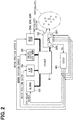
FIG. 2 is a block diagram of an electrical system related to the air conditioning unit in the first embodiment. -
FIG. 3 is a diagram showing relationships among a sensor output value of a particulate sensor, a wind speed at a sensed position, and an actual particulate concentration in the first embodiment. -
FIG. 4 is a flowchart showing control processing performed by a correction section of a particulates detector in the first embodiment. -
FIG. 5 is a schematic diagram showing a correction map used by the correction section to determine a corrected value in the control processing inFIG. 4 . -
FIG. 6 is a block diagram of an electrical system related to an air conditioning unit in a second embodiment and corresponds toFIG. 2 in the first embodiment. -
FIG. 7 is a flowchart showing control processing performed by a correction section of a particulates detector in the second embodiment and corresponds toFIG. 4 in the first embodiment. -
FIG. 8 is a schematic view of an air conditioning unit in a third embodiment and corresponds toFIG. 1 in the first embodiment. -
FIG. 9 is a block diagram of an electrical system related to the air conditioning unit in the third embodiment and corresponds toFIG. 6 in the second embodiment. -
FIG. 10 is a flowchart showing control processing performed by a correction section of a particulates detector in the third embodiment and corresponds toFIG. 7 in the second embodiment. - Respective embodiments will be described below with reference to the drawings. The same or equivalent parts in the following respective embodiments are provided with the same reference signs in the views.
- A
particulates detector 32 in the present embodiment detects a particulate concentration in an air passage formed inside anair conditioning unit 2. First, an overview of a structure of theair conditioning unit 2 will be described. - The
air conditioning unit 2 shown inFIG. 1 is a vehicular air conditioning unit that air-conditions a vehicle interior. Theair conditioning unit 2 is installed in an instrument panel disposed on a vehicle front side in the vehicle interior, for example. - As shown in
FIG. 1 , theair conditioning unit 2 includes anair conditioning case 21, an inside/outsideair switching door 22, ablower 23, anevaporator 26, aheater core 27, anair mix door 28, anair filter 30, theparticulates detector 32, and the like. - The
air conditioning case 21 is made of resin having a certain degree of elasticity and excellent in strength. Examples of the resin forming theair conditioning case 21 include polypropylene. Inside theair conditioning case 21, an air passage through which air flows, i.e., aventilating path 24 is formed. Theair conditioning case 21 has an insideair introducing port 241 for introducing inside air from a predetermined position in the vehicle interior into theventilating path 24 and an outsideair introducing port 242 for introducing outside air from outside of the vehicle into theventilating path 24 on an upstream side of theventilating path 24 in an air flow direction. - A duct (not shown) formed as a separate member from the
air conditioning case 21 may be connected to the insideair introducing port 241 or the outsideair introducing port 242. In this case, air is introduced from the insideair introducing port 241 or the outsideair introducing port 242 into theventilating path 24 through the duct. - The
air conditioning case 21 has a plurality of blow openings 25, for blowing air from theventilating path 24 into a front seat area in the vehicle interior, on a downstream side of theventilating path 24 in the air flow direction. The plurality of blow openings 25 include a face blow opening 251, a foot blow opening 252, and a defroster blow opening 253. - The face blow opening 251 blows conditioned air toward an upper body of an occupant sitting in a front seat. The foot blow opening 252 blows the conditioned air toward feet of the occupant. The defroster blow opening 253 blows the conditioned air toward a windshield of the vehicle.
- Ducts (not shown) formed as separate members from the
air conditioning case 21 may be connected to the face blow opening 251, the foot blow opening 252, and the defroster blow opening 253. In this case, the air flowing out of the face blow opening 251, the foot blow opening 252, and the defroster blow opening 253 is supplied into the vehicle interior from a face blow outlet, a foot blow outlet, and a defroster blow outlet (not shown) provided in the vehicle through the ducts. - In the
air conditioning case 21, the inside/outsideair switching door 22, theblower 23, theevaporator 26, theheater core 27, theair mix door 28, and the like are provided. - The inside/outside
air switching door 22 continuously adjusts an opening area of the insideair introducing port 241 and an opening area of the outsideair introducing port 242. The inside/outsideair switching door 22 is driven by an actuator such as a servomotor (not shown). The inside/outsideair switching door 22 rotates so as to open one of the insideair introducing port 241 and the outsideair introducing port 242 wider as the inside/outsideair switching door 22 closes the other introducing port. In this way, the inside/outsideair switching door 22 can adjust a ratio between volumes of inside air and outside air introduced into the ventilatingpath 24. - The
blower 23 is formed by acentrifugal fan 231, amotor 232 that rotationally drives thecentrifugal fan 231, and the like. When thecentrifugal fan 231 is driven to rotate with themotor 232 of theblower 23, an airflow is formed in the ventilatingpath 24. As a result, the air introduced from the insideair introducing port 241 or the outsideair introducing port 242 into the ventilatingpath 24 flows through the ventilatingpath 24 and is blown out of any of the face blow opening 251, the foot blow opening 252, and the defroster blow opening 253. The face blow opening 251, the foot blow opening 252, and the defroster blow opening 253 are respectively provided with a faceblow opening door 254, a footblow opening door 255, and a defrosterblow opening door 256 for adjusting opening areas of the respective openings. - The
evaporator 26 is a heat exchanger for cooling the air flowing through the ventilatingpath 24. Theheater core 27 is a heat exchanger for heating the air flowing through the ventilatingpath 24. Theheater core 27 is disposed on a downstream side of theevaporator 26 in the air flow direction. - Between the
evaporator 26 and theheater core 27 of theair conditioning unit 2, theair mix door 28 is provided. Theair mix door 28 adjusts a ratio between a volume of air passing through theevaporator 26 and detouring around theheater core 27 and a volume of air passing through theheater core 27 after passing through theevaporator 26. - As shown in
FIGS. 1 and2 , an airconditioning control device 40 is a control device that controls theair conditioning unit 2. To put it concretely, the airconditioning control device 40 is an electronic control unit (i.e., ECU) formed by a microcomputer that performs various air conditioning controls in theair conditioning unit 2. For example, the above-describedblower 23, the inside/outsideair switching door 22, theair mix door 28, the faceblow opening door 254, the footblow opening door 255, and the defrosterblow opening door 256 are driven and controlled by the airconditioning control device 40. - As shown in
FIG. 1 , theair filter 30 is disposed between theblower 23 and theevaporator 26 in the ventilatingpath 24 of theair conditioning case 21. In other words, theair filter 30 is disposed on a downstream side of theblower 23 in the air flow direction and on an upstream side of theevaporator 26 in the air flow direction. - The
air filter 30 traps dust and the like included in the air passing through theair filter 30 to some extent. Therefore, the air blown out of theblower 23 flows into theevaporator 26 after removal of the dust and the like in the air to some extent by theair filter 30. - A
particulates detector 32 is a detecting device for a vehicle and detects a particulate concentration at a predetermined sensed position in the vehicle interior. Then, theparticulates detector 32 outputs a detection signal indicating the particulate concentration to the airconditioning control device 40. - The
particulates detector 32 is disposed between theair filter 30 and theevaporator 26 in the ventilatingpath 24 of theair conditioning case 21. Therefore, the sensed position, i.e., the detected position is a portion in theair conditioning unit 2 provided in the vehicle interior (i.e., a portion in the air conditioning case 21). Specifically, the sensed position is on a downstream side of theair filter 30 in the air flow direction and on the upstream side of theevaporator 26 in the air flow direction in the ventilatingpath 24. - As shown in
FIGS. 1 and2 , theparticulates detector 32 includes aparticulate sensor 321 and acorrection section 322. Thecorrection section 322 is formed integrally with theparticulate sensor 321. Since theparticulates detector 32 is disposed between theblower 23 and theevaporator 26 in the ventilatingpath 24 as described above, theparticulate sensor 321 and thecorrection section 322 are naturally disposed between theblower 23 and theevaporator 26. - The
particulate sensor 321 in the present embodiment is a particulate sensor that detects a particulate concentration by using a light scattering method, i.e., an optical particulate sensor. In other words, theparticulate sensor 321 includes a light source and a light receiving element and detects a particulate concentration by detecting a scattered light with the light receiving element. - The
particulate sensor 321 outputs a sensor output value Vs corresponding to the particulate concentration at a sensed position which is a portion in theair conditioning unit 2. Since the sensor output value Vs is a voltage value in the present embodiment, the sensor output value Vs may be also referred to as "sensor output voltage Vs". The greater the sensor output value Vs which is the voltage value is, the higher particulate concentration the sensor output value Vs indicates. - The
correction section 322 of theparticulates detector 32 is formed by the microcomputer including a CPU, a ROM, a RAM, and the like (not shown). In other words, thecorrection section 322 is an electronic control unit and performs various calculations and processing steps based on a control program stored in the ROM, for example. Semiconductor memories such as the ROM and the RAM are non-transitory tangible storage media. - To put it concretely, the
correction section 322 in the present embodiment determines a corrected value Vc obtained by correcting the sensor output value Vs as a value indicating the particulate concentration at the sensed position. Since the sensor output value Vs is the voltage value in the present embodiment as described above, the corrected value Vc is a voltage value as well. Therefore, the corrected value Vc may be also referred to as the corrected voltage Vc. Similarly to the sensor output value Vs, the greater the corrected value Vc which is the voltage value is, the higher particulate concentration the corrected value Vc indicates. - Here, since the
particulate sensor 321 in the present embodiment is an optical particulate sensor, the sensor output value Vs of theparticulate sensor 321 is influenced by a wind speed at the sensed position. For example, as shown inFIG. 3 , the sensor output values Vs and the sensor output particulate concentrations are correlated to each other so that the sensor output particulate concentration indicated by the sensor output value Vs coincides with the actual particulate concentration when theparticulate sensor 321 detects the particulate concentration at a predetermined criterion wind speed Sd. In this case, a relationship between the sensor output value Vs and the actual particulate concentration is represented by a solid line L0 inFIG. 3 . For example, in the criterion relationship which is the relationship represented by the solid line L0, the sensor output particulate concentration is α when the actual particulate concentration is α. - On the other hand, when the
particulate sensor 321 detects the particulate concentration at a wind speed lower than the criterion wind speed Sd, a relationship between the sensor output value Vs and the actual particulate concentration is represented by a solid line L1, for example. Therefore, even if the actual particulate concentration at the sensed position is constant, the sensor output value Vs indicates the higher sensor output particulate concentration than the actual particulate concentration when the wind speed at the sensed position becomes lower than the criterion wind speed Sd. - When the
particulate sensor 321 detects the particulate concentration at a wind speed higher than the criterion wind speed Sd, a relationship between the sensor output value Vs and the actual particulate concentration is represented by a solid line L2, for example. Therefore, even if the actual particulate concentration at the sensed position is constant, the sensor output value Vs indicates the lower sensor output particulate concentration than the actual particulate concentration when the wind speed at the sensed position becomes higher than the criterion wind speed Sd. - Since the sensor output value Vs changes according to the wind speed at the sensed position in this manner, the
particulates detector 32 includes thecorrection section 322 in addition to theparticulate sensor 321 in order to correct the change. Thecorrection section 322 performs control processing shown in a flowchart inFIG. 4 to suppress the influence of the wind speed on the detection of the particulate concentration. -
FIG. 4 is the flowchart showing the control processing performed by thecorrection section 322. Thecorrection section 322 performs the control processing inFIG. 4 during operation of theair conditioning unit 2, for example. - As shown in
FIG. 4 , thecorrection section 322 first acquires the sensor output value Vs output from theparticulate sensor 321 in step S010. After step S010, thecorrection section 322 goes to step S020. - In step S020, the
correction section 322 acquires wind speed correlated information correlated with the wind speed at the sensed position from the airconditioning control device 40. Examples of the wind speed correlated information include a rotation speed of themotor 232 of theblower 23, a door position of theair mix door 28, a door position of the inside/outsideair switching door 22, respective door positions of theblow opening doors correction section 322 acquires all or any of a plurality of the above-listed examples of information. - Then, the
correction section 322 estimates the wind speed at the sensed position based on the acquired wind speed correlated information. For example, thecorrection section 322 estimates the wind speed at the sensed position by using a map determined in advance by experiments. In this manner, in the present embodiment, thecorrection section 322 indirectly acquires the wind speed at the sensed position based on the wind speed correlated information. After step S020, thecorrection section 322 goes to step S030. - In step S030, the
correction section 322 compares the wind speed at the sensed position acquired in step S020 with the criterion wind speed Sd determined in advance. As a result of the comparison, thecorrection section 322 determines whether there is a difference between the wind speed at the sensed position and the criterion wind speed Sd. A method of determining the criterion wind speed Sd is not especially limited. For example, the criterion wind speed Sd is set to a substantially median wind speed in a range in which the wind speed can change at the sensed position. - For example, the determination in step S030 is not a determination of whether the wind speed at the sensed position closely coincides with the criterion wind speed Sd but a determination of whether the wind speed at the sensed position falls within a predetermined criterion wind speed range including the criterion wind speed Sd as the median wind speed. The predetermined criterion wind speed range is set in advance by experiments to such a range that the influence of the wind speed on the sensor output value Vs can be substantially ignored.
- When the wind speed at the sensed position is outside the criterion wind speed range, the
correction section 322 determines that there is a difference between the wind speed at the sensed position and the criterion wind speed Sd. - On the other hand, when the wind speed at the sensed position is in the criterion wind speed range, the
correction section 322 determines that there is no difference between the wind speed at the sensed position and the criterion wind speed Sd. In other words, in this case, thecorrection section 322 regards the wind speed at the sensed position as the criterion wind speed Sd. - When the
correction section 322 determines that there is a difference between the wind speed at the sensed position and the criterion wind speed Sd in step S030, thecorrection section 322 goes to step S050. On the other hand, when thecorrection section 322 determines that there is no difference between the wind speed at the sensed position and the criterion wind speed Sd, thecorrection section 322 goes to step S040. - In step S040, the
correction section 322 decides to employ the sensor output value Vs acquired in step S010 as it is as the corrected value Vc and outputs the corrected value Vc to the airconditioning control device 40. In short, thecorrection section 322 outputs the sensor output value Vs to the airconditioning control device 40 as it is without correcting the sensor output value Vs. After step S040, thecorrection section 322 returns to step S010. - In step S050, the
correction section 322 determines the corrected value Vc based on the sensor output value Vs and the wind speed at the sensed position and outputs the corrected value Vc to the airconditioning control device 40. In short, thecorrection section 322 corrects the sensor output value Vs and outputs the corrected value to the airconditioning control device 40. - To put it concretely, the corrected value Vc is determined by using a correction map in
FIG. 5 determined in advance. The correction map is obtained by experiments similarly to the graph inFIG. 3 and shows a relationship between the sensor output value Vs and the actual particulate concentration for each wind speed at the sensed position. In other words, the correction map inFIG. 5 is obtained in advance as predetermined relationships among the sensor output value Vs, the actual particulate concentration, and the wind speeds at the sensed position. - For example, a solid line L0 in
FIG. 5 represents the criterion relationship which is the relationship between the sensor output value Vs and the actual particulate concentration when the wind speed at the sensed position is the criterion wind speed Sd. A broken line LS1 represents the relationship between the sensor output value Vs and the actual particulate concentration when the wind speed at the sensed position is a wind speed S1 lower than the criterion wind speed Sd. A broken line LS2 represents the relationship between the sensor output value Vs and the actual particulate concentration when the wind speed at the sensed position is a wind speed S2 lower than the wind speed S1. - A one-dot chain line LS3 represents the relationship between the sensor output value Vs and the actual particulate concentration when the wind speed at the sensed position is a wind speed S3 higher than the criterion wind speed Sd. A one-dot chain line LS4 represents the relationship between the sensor output value Vs and the actual particulate concentration when the wind speed at the sensed position is a wind speed S4 higher than the wind speed S3.
- On a vertical axis in
FIG. 5 , a voltage Voc is a lower limit value of the sensor output value Vs and a voltage Vu is an upper limit value of the sensor output value Vs. The only five relationship lines L0, LS1 to LS4 each of which represents the relationship between the sensor output value Vs and the actual particulate concentration are shown as examples inFIG. 5 , becauseFIG. 5 is a schematic diagram. The actual correction map is formed by a large number of relationship lines. - Next, how to determine the corrected value Vc will be described in a case where the
correction section 322 corrects a certain value (specifically, a voltage V1) obtained as a sensor output value Vs to obtain a corrected value Vc, i.e., the case where the sensor output value Vs is the voltage V1, for example. - When the wind speed at the sensed position is the wind speed S1, for example, the broken line LS1 is employed as the relationship line representing the relationship between the sensor output value Vs and the actual particulate concentration in the correction map in
FIG. 5 . Since the sensor output value Vs is the voltage V1 as described above, a point P1L on the broken line LS1 where the sensor output value Vs is the voltage V1 is identified and a point PL on the solid line L0 where the actual particulate concentration is equal to the actual particulate concentration of the point P1L is identified. When the point PL is identified, the voltage VL indicated by the point PL is employed as the corrected value Vc. - In other words, the
correction section 322 obtains the particulate concentration αL corresponding to the wind speed S1 at the sensed position and the voltage V1 which is the certain value obtained as the sensor output value Vs in the correction map inFIG. 5 . Thecorrection section 322 determines the corrected value Vc so that the corrected value Vc becomes the value (i.e., the voltage VL) corresponding to the obtained particulate concentration αL on the solid line L0. - Therefore, in this case, a correction amount which is a difference between the sensor output value Vs and the corrected value Vc is ΔVL which is greater than 0. The corrected value Vc is the voltage VL obtained by correcting the sensor output value Vs as shown by an arrow AL in
FIG. 5 . In other words, as can be seen from a relationship, "VL=V1-ΔVL" in the correction map inFIG. 5 , thecorrection section 322 employs the lower corrected value Vc for the particulate concentration with respect to the sensor output value Vs when the wind speed at the sensed position is lower than the criterion wind speed Sd. To put it concretely, the lower value for the particulate concentration is a value on a lower voltage side. - As can be seen from the plurality of relationship lines L0, LS1, LS2, the lower the wind speed at the sensed position is, the larger the
correction section 322 makes the difference between the sensor output value Vs and the corrected value Vc, when the wind speed at the sensed position is lower than the criterion wind speed Sd. - The corrected value Vc when the wind speed at the sensed position is the wind speed S1 lower than the criterion wind speed Sd is determined as described above. For example, if the air
conditioning control device 40 acquires the voltage V1 which is the sensor output value Vs as it is as a detection signal, the airconditioning control device 40 erroneously recognizes that the particulate concentration is α1. On the other hand, with the correction by using the correction map inFIG. 5 , the airconditioning control device 40 acquires the voltage VL which is the corrected value Vc as the detection signal and therefore can correctly recognize that the particulate concentration is αL. - The corrected value Vc when the wind speed at the sensed position is the wind speed S4 higher than the criterion wind speed Sd is determined in the same way as described above. In other words, when the wind speed at the sensed position is the wind speed S4, the broken line LS4 is employed as the relationship line representing the relationship between the sensor output value Vs and the actual particulate concentration in the correction map in
FIG. 5 . Since the sensor output value Vs is the voltage V1 as described above, a point P1H on the broken line LS4 where the sensor output value Vs is the voltage V1 is identified and a point PH on the solid line L0 where the actual particulate concentration is equal to the actual particulate concentration of the point P1H is identified. When the point PH is identified, the voltage VH indicated by the point PH is employed as the corrected value Vc. - In other words, the
correction section 322 obtains the particulate concentration αH corresponding to the wind speed S4 at the sensed position and the voltage V1 which is the certain value obtained as the sensor output value Vs in the correction map inFIG. 5 . Thecorrection section 322 determines the corrected value Vc so that the corrected value Vc becomes the value (i.e., the voltage VH) corresponding to the obtained particulate concentration αH on the solid line L0. - Therefore, in this case, a correction amount which is a difference between the sensor output value Vs and the corrected value Vc is ΔVH which is greater than 0. The corrected value Vc is the voltage VH obtained by correcting the sensor output value Vs as shown by an arrow AH in
FIG. 5 . In other words, as can be seen from a relationship, "VH=V1+ΔVH" in the correction map inFIG. 5 , thecorrection section 322 employs the higher corrected value Vc for the particulate concentration with respect to the sensor output value Vs when the wind speed at the sensed position is higher than the criterion wind speed Sd. To put it concretely, the higher value for the particulate concentration is a value on a higher voltage side. - As can be seen from the plurality of relationship lines L0, LS3, LS4, the higher the wind speed at the sensed position is, the larger the
correction section 322 makes the difference between the sensor output value Vs and the corrected value Vc, when the wind speed at the sensed position is higher than the criterion wind speed Sd. - The corrected value Vc when the wind speed at the sensed position is the wind speed S4 higher than the criterion wind speed Sd is determined as described above. With the correction by using the correction map in
FIG. 5 , the airconditioning control device 40 acquires the voltage VH which is the corrected value Vc as the detection signal and therefore can correctly recognize that the particulate concentration is αH. - As can be seen from the correction map in
FIG. 5 , the lower the wind speed at the sensed position is, the lower corrected value Vc for the particulate concentration thecorrection section 322 employs, when the sensor output value Vs is fixed whether the wind speed at the sensed position is higher or lower than the criterion wind speed Sd. Here, the sensor output value Vs is fixed, because the corrected value Vc changes according to the sensor output value Vs when the sensor output value Vs changes. In other words, when the sensor output value Vs is fixed refers to when the sensor output value Vs is the certain value (e.g., the voltage V1). Therefore, when the sensor output value Vs is fixed can be referred to as when thecorrection section 322 corrects the certain value obtained as the sensor output value Vs to obtain the corrected value V. After step S050, thecorrection section 322 returns to step S010. - Each processing in each step in
FIG. 4 described above forms a functional unit realizing each function. This holds true for flowcharts inFIGS. 7 and10 described below. - As described above, according to the present embodiment, as shown in
FIG. 5 , the lower the wind speed at the sensed position is, the lower corrected value Vc for the particulate concentration is employed, when the sensor output value Vs is fixed. Therefore, the particulate concentration indicated by the corrected value Vc is the particulate concentration on which the influence of the wind speed at the sensed position is suppressed. Therefore, it is possible to obtain the particulate concentration at the sensed position stably with satisfactory accuracy by using the corrected value Vc. - According to the present embodiment, as shown in
FIGS. 4 and5 , thecorrection section 322 employs the sensor output value Vs as it is as the corrected value Vc when there is no difference between the wind speed at the sensed position and the criterion wind speed Sd. When the wind speed at the sensed position is higher than the criterion wind speed Sd, thecorrection section 322 employs the higher corrected value Vc for the particulate concentration with respect to the sensor output value Vs. Moreover, the higher the wind speed at the sensed position is, the larger thecorrection section 322 makes the difference between the sensor output value Vs and the corrected value Vc. On the other hand, when the wind speed at the sensed position is lower than the criterion wind speed Sd, thecorrection section 322 employs the lower corrected value Vc for the particulate concentration with respect to the sensor output value Vs. Moreover, the lower the wind speed at the sensed position is, the larger thecorrection section 322 makes the difference between the sensor output value Vs and the corrected value Vc. Therefore, whether the wind speed at the sensed position is higher or lower than the criterion wind speed Sd, it is possible to appropriately determine the corrected value Vc while conforming to specific characteristics of the opticalparticulate sensor 321. - According to the present embodiment, as shown in
FIG. 4 , thecorrection section 322 estimates the wind speed at the sensed position based on the wind speed correlated information correlated to the wind speed at the sensed position. Therefore, it is possible to acquire the wind speed at the sensed position without a detector such as a wind speed sensor. - According to the present embodiment, the
correction section 322 obtains the particulate concentration corresponding to the wind speed at the sensed position and the certain value (e.g., the voltage V1) obtained as the sensor output value Vs in the correction map inFIG. 5 . Thecorrection section 322 determines the corrected value Vc so that the corrected value Vc becomes the value (e.g., the voltage VL or the voltage VH) corresponding to the obtained particulate concentration on the solid line L0. - In this way, it is possible to remove the influence of the wind speed at the sensed position from the particulate concentration indicated by the corrected value Vc by using the relationship represented by the solid line L0. Therefore, the particulate concentration indicated by the corrected value Vc is the particulate concentration on which the influence of the wind speed at the sensed position is suppressed. Therefore, it is possible to obtain the particulate concentration at the sensed position with satisfactory accuracy by using the corrected value Vc. While the above-described certain value obtained as the sensor output value Vs is the voltage V1, for example, in
FIG. 5 , it is not limited to a specific value. - Next, the second embodiment will be described. In the present embodiment, differences from the above-described first embodiment will be mainly described. Portions similar or equivalent to those in the above-described embodiment will not be described or will be described briefly. This holds true for the embodiments described later.
- As shown in
FIG. 6 , acorrection section 322 of aparticulates detector 32 is included in an airconditioning control device 40. For example, thecorrection section 322 forms a functional unit of the airconditioning control device 40. The present embodiment is different from the first embodiment in this point. - Therefore, the
correction section 322 in the present embodiment is not disposed in aventilating path 24 of anair conditioning case 21 while aparticulate sensor 321 of theparticulates detector 32 is disposed in the ventilatingpath 24 as shown inFIG. 1 as in the first embodiment. In short, theparticulate sensor 321 is provided separately from the airconditioning control device 40. - The
correction section 322 in the present embodiment performs control processing inFIG. 7 during operation of anair conditioning unit 2, for example. The control processing inFIG. 7 is basically similar to the control processing inFIG. 4 in the first embodiment and has differences from the control processing inFIG. 4 only regarding inclusion of thecorrection section 322 in the airconditioning control device 40. - As shown in
FIG. 7 , thecorrection section 322 in the present embodiment first acquires a sensor output value Vs output from theparticulate sensor 321 in step S011. The sensor output value Vs is input to the airconditioning control device 40 as one of detection signals from sensors and the like connected to the airconditioning control device 40. After step S011, thecorrection section 322 goes to step S021. - In step S021, the
correction section 322 acquires wind speed correlated information from another functional unit of the airconditioning control device 40, for example. Except for this point, step S021 is similar to step S020 inFIG. 4 . - Then, the
correction section 322 estimates a wind speed at a sensed position based on the acquired wind speed correlated information as in step S020 inFIG. 4 . After step S021, thecorrection section 322 goes to step S030. - Since step S030 in
FIG. 7 is similar to step S030 inFIG. 4 , step S030 inFIG. 7 will not be described. - When the
correction section 322 determines that there is a difference between the wind speed at the sensed position and the criterion wind speed Sd in step S030 inFIG. 7 , thecorrection section 322 goes to step S051. On the other hand, when thecorrection section 322 determines that there is no difference between the wind speed at the sensed position and the criterion wind speed Sd, thecorrection section 322 goes to step S041. - In step S041, the
correction section 322 decides to employ the sensor output value Vs acquired in step S011 as it is as a corrected value Vc. Thecorrection section 322 outputs the determined corrected value Vc to functional units of the airconditioning control device 40 other than thecorrection section 322 or external devices such as a display device connected to the airconditioning control device 40, for example. In short, thecorrection section 322 outputs the sensor output value Vs as it is. Although the unit or device to which thecorrection section 322 outputs the sensor output value Vs in step S041 is different from that in step S040 inFIG. 4 , step S041 is the same as step S040 inFIG. 4 in other points. After step S041, thecorrection section 322 returns to step S011 inFIG. 7 . - In step S051, the
correction section 322 determines the corrected value Vc based on the sensor output value Vs and the wind speed at the sensed position. The corrected value Vc is determined in step S051 in the same way as in step S050 inFIG. 4 . Thecorrection section 322 outputs the determined corrected value Vc to functional units of the airconditioning control device 40 other than thecorrection section 322 or external devices such as a display device connected to the airconditioning control device 40, for example. In short, thecorrection section 322 corrects the sensor output value Vs and outputs the corrected value. - Although the unit or device to which the
correction section 322 outputs the corrected value Vc in step S051 is different from that in step S050 inFIG. 4 , step S051 is the same as step S050 inFIG. 4 in other points. After step S051, thecorrection section 322 returns to step S011 inFIG. 7 . - Except for the above described points, the present embodiment is the same as the first embodiment. In the present embodiment, as in the above-described first embodiment, it is possible to obtain effects exerted by the same structures as those in the first embodiment.
- According to the present embodiment, as shown in
FIG. 6 , thecorrection section 322 is included in the airconditioning control device 40 and theparticulate sensor 321 is provided separately from the airconditioning control device 40. Therefore, it is possible to reduce the number of parts of hardware forming thecorrection section 322 as compared with the case where thecorrection section 322 is provided separately from the airconditioning control device 40. - Next, a third embodiment will be described. In the present embodiment, differences from the above-described second embodiment will be mainly described.
- As shown in
FIG. 8 , anair conditioning unit 2 includes awind speed sensor 34. The present embodiment is different from the second embodiment in this point. - To put it concretely, since the
wind speed sensor 34 detects a wind speed at a position sensed by aparticulate sensor 321, thewind speed sensor 34 is provided at the same position as theparticulate sensor 321. In other words, thewind speed sensor 34 is disposed on a downstream side of anair filter 30 in an air flow direction and on an upstream side of anevaporator 26 in the air flow direction in aventilating path 24 of anair conditioning case 21. As shown inFIG. 9 , a detection signal indicating the wind speed at the sensed position is input from thewind speed sensor 34 to an airconditioning control device 40. - A
correction section 322 in the present embodiment performs control processing inFIG. 10 during operation of theair conditioning unit 2, for example. The control processing inFIG. 10 is basically the same as the control processing inFIG. 7 in the second embodiment and is different from the control processing inFIG. 7 only in the method of acquiring the wind speed at the sensed position. To put it concretely, steps S011, S030, S041, S051 inFIG. 10 are the same as steps S011, S030, S041, S051 inFIG. 7 , respectively. Therefore, description of these steps will be omitted and step S022 inFIG. 10 will be described below. - As shown in
FIG. 10 , in step S022 following step S011, thecorrection section 322 acquires the wind speed at the position sensed by theparticulate sensor 321 from thewind speed sensor 34. Therefore, in the present embodiment, the wind speed at the sensed position is not estimated based on the wind speed correlated information but directly detected by thewind speed sensor 34. After step S022, thecorrection section 322 goes to step S030. - Except for the above described point, the present embodiment is the same as the second embodiment. In the present embodiment, as in the above-described second embodiment, it is possible to obtain effects exerted by the same structures as those in the second embodiment.
- According to the present embodiment, as shown in
FIGS. 8 and10 , thewind speed sensor 34 that detects the wind speed at the position sensed by theparticulate sensor 321 is provided. Thecorrection section 322 acquires the wind speed at the sensed position from thewind speed sensor 34. Therefore, it is possible to easily and accurately acquire the wind speed at the sensed position. - Although the present embodiment is a modification of the second embodiment, the present embodiment may be combined with the above-described first embodiment as well.
-
- (1) In each of the above-described embodiments, the position sensed by the
particulate sensor 321 is on the downstream side of theair filter 30 in the air flow direction and on the upstream side of theevaporator 26 in the air flow direction in the ventilatingpath 24 in theair conditioning case 21 as shown inFIGS. 1 and8 , which is only an example. The sensed position may be at one of the plurality of blow openings 251, 252, 253, for example. The sensed position may not be in theair conditioning unit 2. - (2) Although the sensor output value Vs and the corrected value Vc are the voltage values in each of the above-described embodiments, the sensor output value Vs and the corrected value Vc may be physical quantities other than the voltage values, as long as the physical quantities can indicate the particulate concentration.
- (3) In each of the above-described embodiments, the
particulate sensor 321 is the sensor that indicates the higher particulate concentration when the output voltage as the sensor output value Vs is larger, which is only an example. Theparticulate sensor 321 may be a sensor that indicates a higher particulate concentration when an output voltage is smaller. In such a sensor, a low-voltage side of the sensor output value Vs corresponds to a higher side of the particulate concentration indicated by the sensor output value Vs. - (4) In each of the flowcharts in
FIGS. 4 ,7 , and10 in the above-described respective embodiments, the determination in step S030 is performed by determining whether the wind speed at the sensed position falls within the predetermined criterion wind speed range including the criterion wind speed Sd as the median wind speed, which is only an example. For example, the determination in step S030 may be performed by comparing the wind speed at the sensed position and the criterion wind speed Sd with each other and determining whether the wind speed at the sensed position coincides with the criterion wind speed Sd. - (5) Although the processing in each of the steps shown in the flowcharts in
FIGS. 4 ,7 , and10 is realized by the computer program in the above-described respective embodiments, the processing may be formed by a hard wired logic. - (6) The present disclosure is not limited to the above-described embodiments and may be practiced while modified in various ways. The above-described respective embodiments are not unrelated to each other and may be suitably combined with each other unless the combination is obviously impossible. In each of the above-described embodiments, it is needless to say that the components forming the embodiment are not necessarily essential unless the components are especially and clearly described as essential or obviously considered to be essential in principle.
- In each of the above-described embodiments, when numerical values such as the numbers of components forming the embodiment, numerical values, amounts, and ranges are mentioned, the numerical values are not unchangeable unless the numerical values are especially and clearly described as essential or the specific numerical values are obviously unchangeable in principle. In each of the above-described embodiments, when materials, shapes, positional relationships, and the like of the components and the like are mentioned, the materials, the shapes, the positional relationships, and the like are not unchangeable unless otherwise specified or the specific materials, shapes, positional relationships, and the like are unchangeable in principle.
- According to a first aspect disclosed in a part or all of the above-described embodiments, a correction section performs determination of a corrected value, such that a particulate concentration indicated by the corrected value decreases with decrease in wind speed at a sensed position in a case where a sensor output value is fixed.
- According to a second aspect, when there is no difference between the wind speed at the sensed position and a criterion wind speed determined in advance, the correction section determines the corrected value to be the sensor output value. When the wind speed at the sensed position is higher than the criterion wind speed, the correction section determines the corrected value to be higher in the particulate concentration than the sensor output value, and the correction section increases a difference between the sensor output value and the corrected value with increase in wind speed at the sensed position. Therefore, when the wind speed at the sensed position is higher than the criterion wind speed, it is possible to appropriately determine the corrected value while conforming to the specific characteristics of the optical particulate sensor.
- According to a third aspect, when there is no difference between the wind speed at the sensed position and a criterion wind speed determined in advance, the correction section determines the corrected value to be the sensor output value. When the wind speed at the sensed position is lower than the criterion wind speed, the correction section determines the corrected value to be lower in the particulate concentration than the sensor output value, and the correction section increases a difference between the sensor output value and the corrected value with decrease in wind speed at the sensed position. Therefore, when the wind speed at the sensed position is lower than the criterion wind speed, it is possible to appropriately determine the corrected value while conforming to the specific characteristics of the optical particulate sensor.
- According to a fourth aspect, the case where the sensor output value is fixed is a case where a certain value obtained as the sensor output value is corrected for acquiring the corrected value.
- According to a fifth aspect, predetermined relationships among the sensor output value, the actual particulate concentration, and the wind speed at the sensed position are determined in advance. The predetermined relationships include a criterion relationship between the sensor output value and the actual particulate concentration when the wind speed at the sensed position is a criterion wind speed determined in advance. The correction section obtains the particulate concentration from the wind speed at the sensed position and the sensor output value by using the predetermined relationships and determines the corrected value to be a value that corresponds to the obtained particulate concentration in the criterion relationship.
- According to a sixth aspect, the correction section estimates the wind speed at the sensed position based on wind speed correlated information correlated with the wind speed at the sensed position. Therefore, it is possible to acquire the wind speed at the sensed position without a detector such as a wind speed sensor.
- According to a seventh aspect, the correction section acquires the wind speed at the sensed position from a wind speed sensor that detects the wind speed at the sensed position. Therefore, it is possible to easily and accurately acquire the wind speed at the sensed position.
- According to an eighth aspect, the sensor output value and the corrected value are voltage values. Therefore, it is possible to use an ordinary optical particulate sensor.
- According to a ninth aspect, the correction section is included in a control device that controls the air conditioning unit; and the optical particulate sensor is provided separately from the control device. Therefore, it is possible to reduce the number of parts of hardware forming the correction section as compared with the case where the correction section is provided separately from the control device.
Claims (9)
- A particulates detector that detects a particulate concentration at a predetermined sensed position, the device comprising:an optical particulate sensor (321) that outputs a sensor output value (Vs) depending on the particulate concentration at the sensed position; anda correction section (322) that determines a corrected value (Vc) by correcting the sensor output value as a value indicating the particulate concentration, wherein,the correction section performs the determination of the corrected value, such that the particulate concentration indicated by the corrected value decreases with decrease in wind speed at the sensed position in a case where the sensor output value is fixed.
- The particulates detector according to claim 1, wherein:when there is no difference between the wind speed at the sensed position and a criterion wind speed (Sd) determined in advance, the correction section determines the corrected value to be the sensor output value; and,when the wind speed at the sensed position is higher than the criterion wind speed, the correction section determines the corrected value to be higher in the particulate concentration than the sensor output value, and the correction section increases a difference between the sensor output value and the corrected value with increase in wind speed at the sensed position.
- The particulates detector according to claim 1, wherein:when there is no difference between the wind speed at the sensed position and a criterion wind speed (Sd) determined in advance, the correction section determines the corrected value to be the sensor output value; and,when the wind speed at the sensed position is lower than the criterion wind speed, the correction section determines the corrected value to be lower in the particulate concentration than the sensor output value, and the correction section increases a difference between the sensor output value and the corrected value with decrease in wind speed at the sensed position.
- The particulates detector according to any one of claims 1 to 3, wherein the case where the sensor output value is fixed is a case where a certain value (V1) obtained as the sensor output value is corrected for acquiring the corrected value.
- A particulates detector that detects a particulate concentration at a predetermined sensed position, the device comprising:an optical particulate sensor (321) that outputs a sensor output value (Vs) depending on the particulate concentration at the sensed position; anda correction section (322) that determines a corrected value (Vc) by correcting the sensor output value as a value indicating the particulate concentration, wherein:predetermined relationships among the sensor output value, the actual particulate concentration, and the wind speed at the sensed position are determined in advance;the predetermined relationships include a criterion relationship (L0) between the sensor output value and the actual particulate concentration when the wind speed at the sensed position is a criterion wind speed (Sd) determined in advance; andthe correction section obtains the particulate concentration from the wind speed at the sensed position and the sensor output value by using the predetermined relationships and determines the corrected value to be a value that corresponds to the obtained particulate concentration in the criterion relationship.
- The particulates detector according to any one of claims 1 to 5, wherein the correction section estimates the wind speed at the sensed position based on wind speed correlated information correlated with the wind speed at the sensed position.
- The particulates detector according to any one of claims 1 to 5, wherein the correction section acquires the wind speed at the sensed position from a wind speed sensor (34) that detects the wind speed at the sensed position.
- The particulates detector according to any one of claims 1 to 7, wherein the sensor output value and the corrected value are voltage values.
- The particulates detector according to any one of claims 1 to 8, wherein:the sensed position is a portion in an air conditioning unit (2) provided in a vehicle interior;the correction section is included in a control device (40) that controls the air conditioning unit; andthe optical particulate sensor is provided separately from the control device.
Applications Claiming Priority (2)
| Application Number | Priority Date | Filing Date | Title |
|---|---|---|---|
| JP2017006972A JP2018115959A (en) | 2017-01-18 | 2017-01-18 | Dust detection device |
| PCT/JP2017/047107 WO2018135284A1 (en) | 2017-01-18 | 2017-12-27 | Dust detecting device |
Publications (3)
| Publication Number | Publication Date |
|---|---|
| EP3572786A1 true EP3572786A1 (en) | 2019-11-27 |
| EP3572786A4 EP3572786A4 (en) | 2020-01-29 |
| EP3572786B1 EP3572786B1 (en) | 2023-02-08 |
Family
ID=62908990
Family Applications (1)
| Application Number | Title | Priority Date | Filing Date |
|---|---|---|---|
| EP17892700.0A Active EP3572786B1 (en) | 2017-01-18 | 2017-12-27 | Dust detecting device |
Country Status (4)
| Country | Link |
|---|---|
| EP (1) | EP3572786B1 (en) |
| JP (1) | JP2018115959A (en) |
| CN (1) | CN110192095B (en) |
| WO (1) | WO2018135284A1 (en) |
Families Citing this family (3)
| Publication number | Priority date | Publication date | Assignee | Title |
|---|---|---|---|---|
| JP7188066B2 (en) * | 2018-12-27 | 2022-12-13 | 株式会社デンソー | Dust detector |
| JPWO2022176727A1 (en) * | 2021-02-16 | 2022-08-25 | ||
| CN119666684B (en) * | 2024-12-09 | 2025-07-08 | 凉山彝族自治州农业科学研究院 | A sheep house environment detection system and method |
Family Cites Families (8)
| Publication number | Priority date | Publication date | Assignee | Title |
|---|---|---|---|---|
| JPH03186244A (en) * | 1989-12-15 | 1991-08-14 | Matsushita Electric Ind Co Ltd | Vacuum cleaner power control device |
| CN1139813C (en) * | 2001-02-26 | 2004-02-25 | 电站锅炉煤清洁燃烧国家工程研究中心 | In-line monitor method and device for flow and concentration of dust-contained airflow |
| JP4470351B2 (en) | 2001-06-12 | 2010-06-02 | パナソニック電工株式会社 | Dust sensor and air purifier |
| JP4426405B2 (en) * | 2004-09-02 | 2010-03-03 | カルソニックカンセイ株式会社 | Air conditioner for vehicles |
| JP2006290001A (en) * | 2005-04-05 | 2006-10-26 | Denso Corp | Vehicle air purifier |
| CN203798704U (en) * | 2014-04-28 | 2014-08-27 | 徐州市计量检定测试中心 | Novel direct-reading type dust concentration measuring instrument verification and calibration device |
| JP6177734B2 (en) * | 2014-07-22 | 2017-08-09 | ダイキン工業株式会社 | Air cleaner |
| JP2017116417A (en) * | 2015-12-24 | 2017-06-29 | シャープ株式会社 | Photoelectric dust sensor and air conditioner |
-
2017
- 2017-01-18 JP JP2017006972A patent/JP2018115959A/en active Pending
- 2017-12-27 EP EP17892700.0A patent/EP3572786B1/en active Active
- 2017-12-27 CN CN201780083657.0A patent/CN110192095B/en active Active
- 2017-12-27 WO PCT/JP2017/047107 patent/WO2018135284A1/en not_active Ceased
Also Published As
| Publication number | Publication date |
|---|---|
| EP3572786A4 (en) | 2020-01-29 |
| CN110192095A (en) | 2019-08-30 |
| WO2018135284A1 (en) | 2018-07-26 |
| EP3572786B1 (en) | 2023-02-08 |
| JP2018115959A (en) | 2018-07-26 |
| CN110192095B (en) | 2022-03-25 |
Similar Documents
| Publication | Publication Date | Title |
|---|---|---|
| US8733428B2 (en) | Air conditioning system for vehicle | |
| EP3572786B1 (en) | Dust detecting device | |
| CN107571713B (en) | Automobile automatic air conditioner control method and controller based on built-in temperature detection unit | |
| CN108688446B (en) | Device for improving air quality in vehicle | |
| CN110573861B (en) | Dust concentration detection device | |
| CN101382027A (en) | Bicycle Window Repositioning to Mitigate Wind Pressure Pulsations in Vehicle Cabins | |
| CN107672408A (en) | A kind of air conditioning for automobiles demisting automatic regulating system | |
| US10618375B2 (en) | Vehicular air-conditioner | |
| JPH1119442A (en) | Air filter clogging detector for car air conditioner | |
| CN113242807B (en) | Air conditioner for vehicle | |
| JP2003072353A (en) | Vehicle air conditioner | |
| CN110290954B (en) | Air conditioner for vehicle | |
| KR101645184B1 (en) | Air conditioning system for automotive vehicles | |
| JP6798454B2 (en) | Vehicle measuring device | |
| US10675944B2 (en) | Vehicular air conditioner | |
| WO2020149065A1 (en) | Pm sensor | |
| KR102045419B1 (en) | Windshield defogging device of automotive vehicles | |
| KR20170029067A (en) | Air conditioning system for automotive vehicles | |
| KR102850882B1 (en) | Air conditioning system for automotive vehicles | |
| CN106240291A (en) | A kind of method calculating vehicle interior temperature | |
| CN109421477A (en) | Automotive air conditioning systems | |
| KR102619397B1 (en) | Air conditioning system for automotive vehicles | |
| JP4033404B2 (en) | A method for air conditioning the interior of a vehicle in response to incident solar radiation | |
| KR20080091575A (en) | Air quality air conditioning control method of car | |
| JP6911819B2 (en) | Vehicle air conditioner |
Legal Events
| Date | Code | Title | Description |
|---|---|---|---|
| STAA | Information on the status of an ep patent application or granted ep patent |
Free format text: STATUS: THE INTERNATIONAL PUBLICATION HAS BEEN MADE |
|
| PUAI | Public reference made under article 153(3) epc to a published international application that has entered the european phase |
Free format text: ORIGINAL CODE: 0009012 |
|
| STAA | Information on the status of an ep patent application or granted ep patent |
Free format text: STATUS: REQUEST FOR EXAMINATION WAS MADE |
|
| 17P | Request for examination filed |
Effective date: 20190716 |
|
| AK | Designated contracting states |
Kind code of ref document: A1 Designated state(s): AL AT BE BG CH CY CZ DE DK EE ES FI FR GB GR HR HU IE IS IT LI LT LU LV MC MK MT NL NO PL PT RO RS SE SI SK SM TR |
|
| AX | Request for extension of the european patent |
Extension state: BA ME |
|
| STAA | Information on the status of an ep patent application or granted ep patent |
Free format text: STATUS: EXAMINATION IS IN PROGRESS |
|
| A4 | Supplementary search report drawn up and despatched |
Effective date: 20200108 |
|
| RIC1 | Information provided on ipc code assigned before grant |
Ipc: G01N 15/06 20060101AFI20191220BHEP Ipc: B60H 1/24 20060101ALI20191220BHEP Ipc: B60H 3/06 20060101ALI20191220BHEP Ipc: B60H 1/00 20060101ALI20191220BHEP |
|
| 17Q | First examination report despatched |
Effective date: 20200122 |
|
| DAV | Request for validation of the european patent (deleted) | ||
| DAX | Request for extension of the european patent (deleted) | ||
| GRAP | Despatch of communication of intention to grant a patent |
Free format text: ORIGINAL CODE: EPIDOSNIGR1 |
|
| STAA | Information on the status of an ep patent application or granted ep patent |
Free format text: STATUS: GRANT OF PATENT IS INTENDED |
|
| INTG | Intention to grant announced |
Effective date: 20221025 |
|
| GRAS | Grant fee paid |
Free format text: ORIGINAL CODE: EPIDOSNIGR3 |
|
| GRAA | (expected) grant |
Free format text: ORIGINAL CODE: 0009210 |
|
| STAA | Information on the status of an ep patent application or granted ep patent |
Free format text: STATUS: THE PATENT HAS BEEN GRANTED |
|
| AK | Designated contracting states |
Kind code of ref document: B1 Designated state(s): AL AT BE BG CH CY CZ DE DK EE ES FI FR GB GR HR HU IE IS IT LI LT LU LV MC MK MT NL NO PL PT RO RS SE SI SK SM TR |
|
| REG | Reference to a national code |
Ref country code: GB Ref legal event code: FG4D |
|
| REG | Reference to a national code |
Ref country code: CH Ref legal event code: EP Ref country code: AT Ref legal event code: REF Ref document number: 1547574 Country of ref document: AT Kind code of ref document: T Effective date: 20230215 |
|
| REG | Reference to a national code |
Ref country code: DE Ref legal event code: R096 Ref document number: 602017065989 Country of ref document: DE |
|
| REG | Reference to a national code |
Ref country code: IE Ref legal event code: FG4D |
|
| REG | Reference to a national code |
Ref country code: LT Ref legal event code: MG9D |
|
| REG | Reference to a national code |
Ref country code: NL Ref legal event code: MP Effective date: 20230208 |
|
| REG | Reference to a national code |
Ref country code: AT Ref legal event code: MK05 Ref document number: 1547574 Country of ref document: AT Kind code of ref document: T Effective date: 20230208 |
|
| PG25 | Lapsed in a contracting state [announced via postgrant information from national office to epo] |
Ref country code: RS Free format text: LAPSE BECAUSE OF FAILURE TO SUBMIT A TRANSLATION OF THE DESCRIPTION OR TO PAY THE FEE WITHIN THE PRESCRIBED TIME-LIMIT Effective date: 20230208 Ref country code: PT Free format text: LAPSE BECAUSE OF FAILURE TO SUBMIT A TRANSLATION OF THE DESCRIPTION OR TO PAY THE FEE WITHIN THE PRESCRIBED TIME-LIMIT Effective date: 20230609 Ref country code: NO Free format text: LAPSE BECAUSE OF FAILURE TO SUBMIT A TRANSLATION OF THE DESCRIPTION OR TO PAY THE FEE WITHIN THE PRESCRIBED TIME-LIMIT Effective date: 20230508 Ref country code: NL Free format text: LAPSE BECAUSE OF FAILURE TO SUBMIT A TRANSLATION OF THE DESCRIPTION OR TO PAY THE FEE WITHIN THE PRESCRIBED TIME-LIMIT Effective date: 20230208 Ref country code: LV Free format text: LAPSE BECAUSE OF FAILURE TO SUBMIT A TRANSLATION OF THE DESCRIPTION OR TO PAY THE FEE WITHIN THE PRESCRIBED TIME-LIMIT Effective date: 20230208 Ref country code: LT Free format text: LAPSE BECAUSE OF FAILURE TO SUBMIT A TRANSLATION OF THE DESCRIPTION OR TO PAY THE FEE WITHIN THE PRESCRIBED TIME-LIMIT Effective date: 20230208 Ref country code: HR Free format text: LAPSE BECAUSE OF FAILURE TO SUBMIT A TRANSLATION OF THE DESCRIPTION OR TO PAY THE FEE WITHIN THE PRESCRIBED TIME-LIMIT Effective date: 20230208 Ref country code: ES Free format text: LAPSE BECAUSE OF FAILURE TO SUBMIT A TRANSLATION OF THE DESCRIPTION OR TO PAY THE FEE WITHIN THE PRESCRIBED TIME-LIMIT Effective date: 20230208 Ref country code: AT Free format text: LAPSE BECAUSE OF FAILURE TO SUBMIT A TRANSLATION OF THE DESCRIPTION OR TO PAY THE FEE WITHIN THE PRESCRIBED TIME-LIMIT Effective date: 20230208 |
|
| PG25 | Lapsed in a contracting state [announced via postgrant information from national office to epo] |
Ref country code: SE Free format text: LAPSE BECAUSE OF FAILURE TO SUBMIT A TRANSLATION OF THE DESCRIPTION OR TO PAY THE FEE WITHIN THE PRESCRIBED TIME-LIMIT Effective date: 20230208 Ref country code: PL Free format text: LAPSE BECAUSE OF FAILURE TO SUBMIT A TRANSLATION OF THE DESCRIPTION OR TO PAY THE FEE WITHIN THE PRESCRIBED TIME-LIMIT Effective date: 20230208 Ref country code: IS Free format text: LAPSE BECAUSE OF FAILURE TO SUBMIT A TRANSLATION OF THE DESCRIPTION OR TO PAY THE FEE WITHIN THE PRESCRIBED TIME-LIMIT Effective date: 20230608 Ref country code: GR Free format text: LAPSE BECAUSE OF FAILURE TO SUBMIT A TRANSLATION OF THE DESCRIPTION OR TO PAY THE FEE WITHIN THE PRESCRIBED TIME-LIMIT Effective date: 20230509 Ref country code: FI Free format text: LAPSE BECAUSE OF FAILURE TO SUBMIT A TRANSLATION OF THE DESCRIPTION OR TO PAY THE FEE WITHIN THE PRESCRIBED TIME-LIMIT Effective date: 20230208 |
|
| PG25 | Lapsed in a contracting state [announced via postgrant information from national office to epo] |
Ref country code: SM Free format text: LAPSE BECAUSE OF FAILURE TO SUBMIT A TRANSLATION OF THE DESCRIPTION OR TO PAY THE FEE WITHIN THE PRESCRIBED TIME-LIMIT Effective date: 20230208 Ref country code: RO Free format text: LAPSE BECAUSE OF FAILURE TO SUBMIT A TRANSLATION OF THE DESCRIPTION OR TO PAY THE FEE WITHIN THE PRESCRIBED TIME-LIMIT Effective date: 20230208 Ref country code: EE Free format text: LAPSE BECAUSE OF FAILURE TO SUBMIT A TRANSLATION OF THE DESCRIPTION OR TO PAY THE FEE WITHIN THE PRESCRIBED TIME-LIMIT Effective date: 20230208 Ref country code: DK Free format text: LAPSE BECAUSE OF FAILURE TO SUBMIT A TRANSLATION OF THE DESCRIPTION OR TO PAY THE FEE WITHIN THE PRESCRIBED TIME-LIMIT Effective date: 20230208 Ref country code: CZ Free format text: LAPSE BECAUSE OF FAILURE TO SUBMIT A TRANSLATION OF THE DESCRIPTION OR TO PAY THE FEE WITHIN THE PRESCRIBED TIME-LIMIT Effective date: 20230208 |
|
| REG | Reference to a national code |
Ref country code: DE Ref legal event code: R097 Ref document number: 602017065989 Country of ref document: DE |
|
| PG25 | Lapsed in a contracting state [announced via postgrant information from national office to epo] |
Ref country code: SK Free format text: LAPSE BECAUSE OF FAILURE TO SUBMIT A TRANSLATION OF THE DESCRIPTION OR TO PAY THE FEE WITHIN THE PRESCRIBED TIME-LIMIT Effective date: 20230208 |
|
| PLBE | No opposition filed within time limit |
Free format text: ORIGINAL CODE: 0009261 |
|
| STAA | Information on the status of an ep patent application or granted ep patent |
Free format text: STATUS: NO OPPOSITION FILED WITHIN TIME LIMIT |
|
| 26N | No opposition filed |
Effective date: 20231109 |
|
| PG25 | Lapsed in a contracting state [announced via postgrant information from national office to epo] |
Ref country code: SI Free format text: LAPSE BECAUSE OF FAILURE TO SUBMIT A TRANSLATION OF THE DESCRIPTION OR TO PAY THE FEE WITHIN THE PRESCRIBED TIME-LIMIT Effective date: 20230208 |
|
| PG25 | Lapsed in a contracting state [announced via postgrant information from national office to epo] |
Ref country code: IT Free format text: LAPSE BECAUSE OF FAILURE TO SUBMIT A TRANSLATION OF THE DESCRIPTION OR TO PAY THE FEE WITHIN THE PRESCRIBED TIME-LIMIT Effective date: 20230208 |
|
| REG | Reference to a national code |
Ref country code: CH Ref legal event code: PL |
|
| PG25 | Lapsed in a contracting state [announced via postgrant information from national office to epo] |
Ref country code: LU Free format text: LAPSE BECAUSE OF NON-PAYMENT OF DUE FEES Effective date: 20231227 |
|
| PG25 | Lapsed in a contracting state [announced via postgrant information from national office to epo] |
Ref country code: MC Free format text: LAPSE BECAUSE OF FAILURE TO SUBMIT A TRANSLATION OF THE DESCRIPTION OR TO PAY THE FEE WITHIN THE PRESCRIBED TIME-LIMIT Effective date: 20230208 |
|
| GBPC | Gb: european patent ceased through non-payment of renewal fee |
Effective date: 20231227 |
|
| REG | Reference to a national code |
Ref country code: BE Ref legal event code: MM Effective date: 20231231 |
|
| PG25 | Lapsed in a contracting state [announced via postgrant information from national office to epo] |
Ref country code: MC Free format text: LAPSE BECAUSE OF FAILURE TO SUBMIT A TRANSLATION OF THE DESCRIPTION OR TO PAY THE FEE WITHIN THE PRESCRIBED TIME-LIMIT Effective date: 20230208 Ref country code: LU Free format text: LAPSE BECAUSE OF NON-PAYMENT OF DUE FEES Effective date: 20231227 |
|
| REG | Reference to a national code |
Ref country code: IE Ref legal event code: MM4A |
|
| PG25 | Lapsed in a contracting state [announced via postgrant information from national office to epo] |
Ref country code: IE Free format text: LAPSE BECAUSE OF NON-PAYMENT OF DUE FEES Effective date: 20231227 |
|
| PG25 | Lapsed in a contracting state [announced via postgrant information from national office to epo] |
Ref country code: GB Free format text: LAPSE BECAUSE OF NON-PAYMENT OF DUE FEES Effective date: 20231227 |
|
| PG25 | Lapsed in a contracting state [announced via postgrant information from national office to epo] |
Ref country code: BE Free format text: LAPSE BECAUSE OF NON-PAYMENT OF DUE FEES Effective date: 20231231 |
|
| PG25 | Lapsed in a contracting state [announced via postgrant information from national office to epo] |
Ref country code: FR Free format text: LAPSE BECAUSE OF NON-PAYMENT OF DUE FEES Effective date: 20231231 |
|
| PG25 | Lapsed in a contracting state [announced via postgrant information from national office to epo] |
Ref country code: CH Free format text: LAPSE BECAUSE OF NON-PAYMENT OF DUE FEES Effective date: 20231231 |
|
| PG25 | Lapsed in a contracting state [announced via postgrant information from national office to epo] |
Ref country code: IE Free format text: LAPSE BECAUSE OF NON-PAYMENT OF DUE FEES Effective date: 20231227 Ref country code: GB Free format text: LAPSE BECAUSE OF NON-PAYMENT OF DUE FEES Effective date: 20231227 Ref country code: FR Free format text: LAPSE BECAUSE OF NON-PAYMENT OF DUE FEES Effective date: 20231231 Ref country code: CH Free format text: LAPSE BECAUSE OF NON-PAYMENT OF DUE FEES Effective date: 20231231 Ref country code: BE Free format text: LAPSE BECAUSE OF NON-PAYMENT OF DUE FEES Effective date: 20231231 |
|
| PG25 | Lapsed in a contracting state [announced via postgrant information from national office to epo] |
Ref country code: BG Free format text: LAPSE BECAUSE OF FAILURE TO SUBMIT A TRANSLATION OF THE DESCRIPTION OR TO PAY THE FEE WITHIN THE PRESCRIBED TIME-LIMIT Effective date: 20230208 |
|
| PG25 | Lapsed in a contracting state [announced via postgrant information from national office to epo] |
Ref country code: BG Free format text: LAPSE BECAUSE OF FAILURE TO SUBMIT A TRANSLATION OF THE DESCRIPTION OR TO PAY THE FEE WITHIN THE PRESCRIBED TIME-LIMIT Effective date: 20230208 |
|
| PG25 | Lapsed in a contracting state [announced via postgrant information from national office to epo] |
Ref country code: CY Free format text: LAPSE BECAUSE OF FAILURE TO SUBMIT A TRANSLATION OF THE DESCRIPTION OR TO PAY THE FEE WITHIN THE PRESCRIBED TIME-LIMIT; INVALID AB INITIO Effective date: 20171227 |
|
| PG25 | Lapsed in a contracting state [announced via postgrant information from national office to epo] |
Ref country code: HU Free format text: LAPSE BECAUSE OF FAILURE TO SUBMIT A TRANSLATION OF THE DESCRIPTION OR TO PAY THE FEE WITHIN THE PRESCRIBED TIME-LIMIT; INVALID AB INITIO Effective date: 20171227 |
|
| PG25 | Lapsed in a contracting state [announced via postgrant information from national office to epo] |
Ref country code: TR Free format text: LAPSE BECAUSE OF FAILURE TO SUBMIT A TRANSLATION OF THE DESCRIPTION OR TO PAY THE FEE WITHIN THE PRESCRIBED TIME-LIMIT Effective date: 20230208 |
|
| PGFP | Annual fee paid to national office [announced via postgrant information from national office to epo] |
Ref country code: DE Payment date: 20251211 Year of fee payment: 9 |