EP3572776A1 - Bemessungshilfe - Google Patents
Bemessungshilfe Download PDFInfo
- Publication number
- EP3572776A1 EP3572776A1 EP19173782.4A EP19173782A EP3572776A1 EP 3572776 A1 EP3572776 A1 EP 3572776A1 EP 19173782 A EP19173782 A EP 19173782A EP 3572776 A1 EP3572776 A1 EP 3572776A1
- Authority
- EP
- European Patent Office
- Prior art keywords
- vessel
- volume
- filled
- level
- determined
- Prior art date
- Legal status (The legal status is an assumption and is not a legal conclusion. Google has not performed a legal analysis and makes no representation as to the accuracy of the status listed.)
- Granted
Links
Images


Classifications
-
- G—PHYSICS
- G01—MEASURING; TESTING
- G01F—MEASURING VOLUME, VOLUME FLOW, MASS FLOW OR LIQUID LEVEL; METERING BY VOLUME
- G01F23/00—Indicating or measuring liquid level or level of fluent solid material, e.g. indicating in terms of volume or indicating by means of an alarm
- G01F23/22—Indicating or measuring liquid level or level of fluent solid material, e.g. indicating in terms of volume or indicating by means of an alarm by measuring physical variables, other than linear dimensions, pressure or weight, dependent on the level to be measured, e.g. by difference of heat transfer of steam or water
- G01F23/28—Indicating or measuring liquid level or level of fluent solid material, e.g. indicating in terms of volume or indicating by means of an alarm by measuring physical variables, other than linear dimensions, pressure or weight, dependent on the level to be measured, e.g. by difference of heat transfer of steam or water by measuring the variations of parameters of electromagnetic or acoustic waves applied directly to the liquid or fluent solid material
- G01F23/284—Electromagnetic waves
- G01F23/292—Light, e.g. infrared or ultraviolet
-
- G—PHYSICS
- G01—MEASURING; TESTING
- G01F—MEASURING VOLUME, VOLUME FLOW, MASS FLOW OR LIQUID LEVEL; METERING BY VOLUME
- G01F22/00—Methods or apparatus for measuring volume of fluids or fluent solid material, not otherwise provided for
Definitions
- the invention relates to the dimensioning of a volume to be filled into a vessel.
- the invention relates to the design of an ingredient in the preparation of a food.
- predetermined amounts of ingredients are usually mixed together in a vessel.
- the metering of an ingredient may interrupt the preparation process and require additional equipment, such as a scale or measuring cup. In both, remnants of the metered ingredient may remain, thereby losing some of the ingredient and falsifying the recipe.
- a spoon with an integrated scale can be used. But such a spoon is only partially suitable for the further processing of ingredients.
- US 9,460,562 B2 suggests a camera attached to the head of a user, by means of which optical magnitudes of objects are determined. From this, the size of an interior of the vessel can be determined.
- One underlying technique of the present invention is to provide an improved technique for simplifying the sizing of an ingredient in, for example, cooking a meal.
- the invention solves this problem by means of the subjects of the independent claims. Subclaims give preferred embodiments again.
- a method according to the invention in particular for simplifying a dimensioning of a substance during the preparation of a food, comprises steps of detecting a volume to be filled into a vessel; optically scanning an interior of the vessel from a predetermined height above the vessel; determining a level that the volume causes after it has been filled in the vessel; and displaying the specific level.
- a recipe can be provided. Based on the recipe, a substance to be filled into the vessel, in particular an ingredient, can be determined. The volume of the substance to be filled can be determined on the basis of the weight of the substance to be filled and a mass density of the substance. In this way, a user can be helped with cooking.
- a volume of the interior can be determined improved. In particular, it can be more easily determined which level should result after filling the volume on the vessel.
- the method is generally suitable for a volume of a liquid or bulk material, and more preferably can be carried out in the preparation of a dish.
- the volume may concern, for example, water, milk, oil or wine.
- the bulk material may include sugar, flour or semolina.
- the volume may be predetermined, for example, from a recipe. The method can be applied to any vessel.
- the material from which the predetermined volume is to be filled into the vessel may be arbitrary.
- the vessel may abut a work surface, the scan being from a predetermined height above the work surface.
- the vessel can stand on the work surface.
- the resulting level can be easily determined.
- it can also be scanned against the work surface inclined vessel.
- the slope may facilitate a user to manipulate a content of the vessel, such as by stirring.
- the abutment on the work surface can ensure that predetermined distances are maintained so that a determination of geometric relationships of the vessel due to an image of the optical scan is correct.
- the shape of the interior may be determined on the basis of the scan. This can be done several scans from different perspectives in the manner of a stereo camera. Also, a depth camera may be used that can provide distance information based on, for example, the propagation speed of light.
- the interior can be scanned as a three-dimensional hollow body.
- the shape of the interior can be determined in consideration of an interior object.
- an interior object For example, is another ingredient already in the Vessel, the space available for the volume to be filled in can be determined by interpreting the other ingredient as part of the vessel.
- the other ingredient may, for example, comprise a liquid which forms a mirror, which is usually parallel to the working surface, or a bulk material which may form a cone or a hill in the vessel. Even an irregularly shaped ingredient such as a piece of butter can be visually scanned and taken into account.
- a mark pointing to the specific fill level can be projected onto a wall of the vessel.
- the projection can be on the inside of the vessel so that a user can easily fill in as much volume of the material to be added as predetermined. If a material of the vessel is transparent, the projection can also take place on the outside.
- an image projector or a controllable laser pointer can be used.
- the volume to be filled can be determined on the basis of the weight of the substance to be filled and a mass density of the substance. For this purpose, a catalog of mass densities of different goods can be kept. So it can be easily determined which volume, for example, take 200 g of flour or 200 g of ground almonds.
- a filling level in the vessel can be determined as a function of a filled volume.
- a relationship between the level and the volume can be determined in the manner of a function or a table. This determination can be used for a subsequent filling process.
- the relationship can also take into account an irregularly shaped or partially filled with an object vessel.
- a device in particular for simplifying a dimensioning of a substance during the preparation of a food, comprises an optical scanning device which is set up for mounting at a predetermined height above a vessel, the optical scanning device being adapted for optically scanning an interior of the vessel; a processing device adapted to determine a level that the volume causes after it has been filled in the vessel; and a display device for displaying the determined level.
- the processing device may be further configured to base a substance to be filled into the vessel determine on a prescription and / or determine a volume of the substance to be filled into the vessel on the basis of a weight of the substance to be filled in and a mass density of the substance.
- the display device can be configured as a projector.
- the scanning device may in particular comprise one or more cameras, a stereo camera or a depth camera.
- the display device may comprise an image projector or controllable laser pointer, which are set up to display a mark pointing at a fill level to be taken on the vessel.
- a remote from the vessel mounted optical display an audible or haptic display.
- a display device attachable to a user's head can be used, for example, virtual reality (VR) glasses. In this case, a corresponding brand can be reflected in the field of view that sets for the user the impression of a display on the vessel.
- VR virtual reality
- the processing device is preferably set up to partially or completely carry out a method described herein.
- the processing device can be designed as a programmable microcomputer or microcontroller and the method can be in the form of a computer program product with program code means.
- the computer program product can also be stored on a computer-readable data carrier. Advantages or features of the method can be transferred to the device and vice versa.
- the optical scanning device may be formed as a depth camera, which is set up to determine distances of points of a boundary of the interior of the depth camera.
- the depth camera may comprise a device for determining distance, for example in the manner of a LiDAR or a stereo camera.
- An optical camera for providing a two-dimensional image may be additionally used.
- the apparatus may further comprise a projector for projecting a mark indicative of the particular level to a wall of the vessel.
- the projector can be integrated with the camera and optionally the depth camera.
- the device may be combined with an interaction device configured to be mounted over a work surface in a kitchen.
- a function of the interaction device such as the administration or presentation of a cooking recipe, may be supplemented or supported by the described device or method.
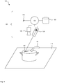
- FIG. 1 shows a system 100 with a device 105 for assisting a sizing operation.
- a vessel or container 110 is in contact with a work surface 115.
- the apparatus 105 is mounted such that an optical path to the vessel 110 is as free and unobstructed as possible.
- the vessel 110 may include a pot or bowl, and the work surface 115 may include a heater that may be configured to heat the vessel 110.
- a predetermined volume of a product 120 or a substance is to be filled, which is preferably at least partially flowable, so that after filling a level in the vessel 110 can be determined.
- the material 120 may comprise, for example, a fluid such as water or a bulk material such as wheat semolina.
- the level also called level, is determined as the height of flowable material in the vessel 110.
- the device 105 comprises an optical scanning device 125, a processing device 130 and a display device 135.
- the scanning device 125 is configured to optically scan an interior of the vessel 110.
- the processing device is configured to determine a fill level that occurs after filling a predetermined volume in the vessel 110.
- the display device 135 is configured to display the determined level.
- the display device 135 may be configured to display the specific fill level directly on the vessel 110.
- an optical mark 140 is thrown onto the vessel 110, for example by means of a projector or a laser pointer.
- the mark 140 may also be mirrored into the field of vision of a user by means of virtual reality so that it visually perceives the mark 140 on the vessel 110.
- a symbolic or numerical indication are displayed optically, for example by means of a dedicated display device.
- a projection of the reference to the work surface 115 or another surface in the area of the system 100 is conceivable.
- the processing device 130 is connected to an interface 145, via which the volume to be filled can be received.
- the material to be filled 120 and the mass to be filled can also be detected via the interface 145.
- the volume may then be determined based on a bulk density of the stock 120. Bulk densities of one or more different goods may be stored in a storage device 150.
- the device 105 can also be embodied integrated with an interaction system which is set up to detect and process a gesture of a user in the area of the work surface 115 and to control a projection in the area of the work surface 115.
- the interaction system may be configured to guide a user through processing steps of a cooking recipe. From the recipe, which may for example be received via the interface 145 or stored in the storage device 150, an amount or a volume of a product 120 to be filled into the vessel 110 may be taken.
- the apparatus 105 may be mounted in a kitchen above the work surface 115 by attaching it to a wall or above the work surface 115 Furniture is attached.
- the furniture may in particular comprise a cabinet or a shelf.
- the components of the device 105 are housed in a housing that protects them from contamination, especially by water or food.
- FIG. 2 shows a flow chart of a method 200 for supporting a sizing operation.
- the method 200 can be carried out in particular in connection with the device 105.
- a volume to be filled into the vessel 110 is determined.
- the material 120 to be filled can be taken into account, for example in order to determine the volume from a mass specification.
- the vessel 110 is optically scanned.
- the volume of the interior of the vessel 110 that can be absorbed by the product 120 can be determined on the basis of the optical scanning.
- the shape of the free volume can be determined and their relationship between the level and a filled volume can be determined. For example, if it is a vessel 110, the interior of which has the shape of a cylinder which is located on the work surface 115, there may be a linear relationship. A proportionality factor can be dependent on the size of a bottom surface of the cylinder. Other shapes of the interior may also define a linear relationship, for example a cuboid or a slate cylinder.
- the free volume and the expected level may possibly be determined geometrically.
- the basis for such determinations are usually lengths or distances which can be determined on the basis of the optical scanning.
- the interior can also be composed of several forms that can be treated individually. Thus, for example, the interior of the form of a resting on a straight circular cylinder inverted truncated cone.
- the volume, shape or relationship between level and free volume may be known for a predetermined vessel 110.
- Corresponding information can be stored in the data memory 150. If a plurality of vessels 110 can be used, they may be based on optical features, an optical code - such as one Bar or QR codes - or identified, for example, by means of an RFID tag. A corresponding reader may be included in the device 105.
- the level of the vessel 110 is determined when the predetermined volume is filled. This determination can be made on the basis of the previously determined relationship between level and free volume.
- the specific fill level can be displayed.
- the mark 140 is preferably projected onto the vessel 110, so that a user only has to fill the vessel 110 into the vessel 110 until the level that he observes has reached the mark 140.
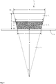
- FIG. 3 shows a conical vessel 110 in cross section.
- the vessel 110 may, for example, have a conical or pyramidal interior.
- the area shown in dark is already filled, so that the region shown bright above is available as a free volume V c for receiving the product 120.
- the entire volume of the interior of the vessel 110 is V p and is assumed to be known.
- the thickness of a bottom or wall of the vessel 110 is not considered.
- the level is designated as h.
- the mark 140 can be displayed if either h or the length of the line 1 is known, which runs on the inside of the vessel 110 parallel to the work surface 115 at the level of the filling level.
- V C 1 3 * ⁇ * b 2 2 + b 2 * c 2 + c 2 2 * a
- V P 1 3 b 2 + b * c + c 2 * a
- V T V R + V i
- V T C 1 3 * ⁇ * l 2 2 * d + H
- V T P 1 3 * l 2 * d + H
- V i c 1 3 * ⁇ * c 2 2 * d
- V i p 1 3 * c 2 * d
- V T C 1 3 ⁇ l 2 2 d + H
- V i c 1 3 ⁇ c 2 2 d
- V T P 1 3 l 2 d + H V i P + 1 3 c 2 d
- FIG. 4 shows a side view of a vessel 110, in which by means of the projector 135, a mark 140 is projected.
- the angle ⁇ corresponds to that of FIG. 3 ,
- the light cone emitted by the projector 135 forms on the work surface 115 a spot with a diameter of rl.
- a projection can be controlled in which the light spot on the work surface 115 would have a diameter which causes the emitted light cone at the correct height h to hit an inner boundary of the vessel 110. If the product 120 is filled into the vessel, the predetermined fill level is exceeded if only a concentric part of the surface of the filled product 120 is illuminated by the projector.
Landscapes
- Physics & Mathematics (AREA)
- Electromagnetism (AREA)
- Fluid Mechanics (AREA)
- General Physics & Mathematics (AREA)
- Thermal Sciences (AREA)
- Length Measuring Devices By Optical Means (AREA)
Abstract
Description
- Die Erfindung betrifft die Bemessung eines in ein Gefäß einzufüllenden Volumens. Insbesondere betrifft die Erfindung die Bemessung einer Zutat bei der Zubereitung einer Speise.
- Zur Zubereitung einer Speise werden üblicherweise vorbestimmte Mengen von Zutaten in einem Gefäß miteinander vermengt. Das Abmessen einer Zutat kann den Zubereitungsprozess unterbrechen und zusätzliches Gerät erfordern, beispielsweise eine Waage oder einen Messbecher. In beiden können Reste der abgemessenen Zutat zurückbleiben, wodurch ein Teil der Zutat verloren gehen und das Rezept verfälscht werden kann.
- Zur Erleichterung der Bemessung einer Zutat wurden verschiedene Vorschläge gemacht. Beispielsweise kann ein Löffel mit einer integrierten Waage verwendet werden. Ein solcher Löffel ist aber für die weitere Verarbeitung von Zutaten nur bedingt geeignet.
-
US 9,460,562 B2 - Eine der vorliegenden Erfindung zu Grunde liegende Technik besteht in der Bereitstellung einer verbesserten Technik, mit der eine Bemessung einer Zutat beispielsweise beim Zubereiten einer Speise vereinfacht werden kann. Die Erfindung löst diese Aufgabe mittels der Gegenstände der unabhängigen Ansprüche. Unteransprüche geben bevorzugte Ausführungsformen wieder.
- Ein erfindungsgemäßes Verfahren, insbesondere zur Vereinfachung einer Bemessung einer Substanz beim Zubereiten einer Speise, umfasst Schritte des Erfassens eines in ein Gefäß einzufüllenden Volumens; optisches Abtasten eines Innenraums des Gefäßes von einer vorbestimmten Höhe über dem Gefäß aus; des Bestimmens eines Füllstands, den das Volumen nach seinem Einfüllen im Gefäß bewirkt; und des Anzeigens des bestimmten Füllstands. Zuvor kann ein Rezept bereitgestellt werden. Basierend auf dem Rezept kann eine in das Gefäß einzufüllende Substanz, insbesondere eine Zutat, bestimmt werden. Das einzufüllende Volumen der einzufüllenden Substanz kann auf der Basis des Gewichts der einzufüllenden Substanz und einer Massendichte der Substanz bestimmt werden. Auf diese Weise kann ein Nutzer beim Kochen unterstützt werden.
- Durch die vorbestimmte Höhe, aus der das Gefäß optisch abgetastet wird, kann ein Volumen des Innenraums verbessert bestimmt werden. Insbesondere kann leichter bestimmt werden, welcher Füllstand sich nach dem Einfüllen des Volumens am Gefäß ergeben sollte. Das Verfahren ist allgemein für ein Volumen einer Flüssigkeit oder eines Schüttguts geeignet und kann besonders bevorzugt im Rahmen der Zubereitung eines Gerichts durchgeführt werden. Hier kann das Volumen beispielsweise Wasser, Milch, Öl oder Wein betreffen. Das Schüttgut kann etwa Zucker, Mehl oder Grieß umfassen. Das Volumen kann beispielsweise aus einem Rezept vorgegeben sein. Das Verfahren kann an einem beliebigen Gefäß angewendet werden. Das Gut, von dem das vorbestimmte Volumen in das Gefäß einzufüllen ist, kann beliebig sein.
- Das Gefäß kann an einer Arbeitsfläche anliegen, wobei die Abtastung aus einer vorbestimmten Höhe über der Arbeitsfläche erfolgt. In einer einfachen Ausführungsform kann das Gefäß auf der Arbeitsfläche stehen. Insbesondere wenn das Gefäß auf seiner Innenseite regelmäßig geformt ist, kann der sich ergebende Füllstand leicht bestimmt werden. Es kann aber auch ein gegenüber der Arbeitsfläche geneigtes Gefäß abgetastet werden. Die Neigung kann es einem Benutzer erleichtern, einen Inhalt des Gefäßes zu bearbeiten, beispielsweise durch Rühren. Das Anliegen an der Arbeitsfläche kann sicherstellen, dass vorbestimmte Abstände eingehalten sind, sodass eine Bestimmung von geometrischen Verhältnissen des Gefäßes aufgrund eines Bildes der optischen Abtastung korrekt ist.
- Alternativ dazu kann die Form des Innenraums auf der Basis der Abtastung bestimmt wird. Dazu können mehrere Abtastungen aus unterschiedlichen Perspektiven nach Art einer Stereo-Kamera erfolgen. Es kann auch eine Tiefenkamera verwendet werden, die Entfernungsinformationen beispielsweise auf der Basis der Ausbreitungsgeschwindigkeit von Licht bereitstellen kann. Der Innenraum kann so als dreidimensionaler Hohlkörper abgetastet werden.
- Die Form des Innenraums kann unter Berücksichtigung eines sich im Innenraum befindlichen Objekts bestimmt werden. Befindet sich beispielsweise eine andere Zutat bereits im Gefäß, so kann der für das einzufüllende Volumen zur Verfügung stehende Platz bestimmt werden, indem die andere Zutat als Teil des Gefäßes interpretiert wird. Die andere Zutat kann beispielsweise eine Flüssigkeit umfassen, die einen üblicherweise zur Arbeitsfläche parallelen Spiegel bildet, oder ein Schüttgut, das einen Konus oder Hügel im Gefäß bilden kann. Auch eine unregelmäßig geformte Zutat wie ein Stück Butter kann optisch abgetastet und berücksichtigt werden.
- In einer Fortführung des Verfahrens kann eine auf den bestimmten Füllstand hinweisende Marke an eine Wand des Gefäßes projiziert werden. Die Projektion kann auf der Innenseite des Gefäßes erfolgen, sodass ein Benutzer leicht ein so großes Volumen des hinzuzufügenden Guts einfüllen kann wie vorbestimmt. Ist ein Material des Gefäßes transparent, so kann die Projektion auch auf der Außenseite erfolgen. Zur Projektion kann beispielsweise ein Bildprojektor oder ein steuerbarer Laserzeiger verwendet werden.
- Das einzufüllende Volumen kann auf der Basis des Gewichts der einzufüllenden Substanz und einer Massendichte der Substanz bestimmt werden. Dazu kann ein Katalog von Massendichten unterschiedlicher Güter vorgehalten sein. So kann leicht bestimmt werden, welches Volumen beispielsweise 200 g Mehl oder 200 g gemahlene Mandeln einnehmen.
- Ein sich im Gefäß einstellender Füllstand kann in Abhängigkeit eines eingefüllten Volumens bestimmt werden. Insbesondere kann ein Zusammenhang zwischen dem Füllstand und dem Volumen nach Art einer Funktion oder einer Tabelle bestimmt werden. Diese Bestimmung kann für einen folgenden Einfüllvorgang weiter verwendet werden. Der Zusammenhang kann auch ein unregelmäßig geformtes oder teilweise mit einem Objekt ausgefülltes Gefäß berücksichtigen.
- Eine erfindungsgemäße Vorrichtung, insbesondere zur Vereinfachung einer Bemessung einer Substanz beim Zubereiten einer Speise, umfasst eine optische Abtasteinrichtung, die zur Anbringung in einer vorbestimmten Höhe über einem Gefäß eingerichtet ist, wobei die optische Abtasteinrichtung zur optischen Abtastung eines Innenraums des Gefäßes eingerichtet ist; eine Verarbeitungseinrichtung, die dazu eingerichtet ist, einen Füllstand zu bestimmen, den das Volumen nach seinem Einfüllen im Gefäß bewirkt; und eine Anzeigeeinrichtung zur Anzeige des bestimmten Füllstands. Die Verarbeitungseinrichtung kann weiter dazu eingerichtet sein, eine in das Gefäß einzufüllende Substanz basierend auf einem Rezept zu bestimmen und/oder ein in das Gefäß einzufüllendes Volumen der einzufüllenden Substanz auf der Basis eines Gewichts der einzufüllenden Substanz und einer Massendichte der Substanz zu bestimmen. Die Anzeigeeinrichtung kann als Projektor ausgestaltet sein.
- Die Abtasteinrichtung kann insbesondere eine oder mehrere Kameras, eine Stereo-Kamera oder eine Tiefenkamera umfassen. Die Anzeigevorrichtung kann insbesondere einen Bildprojektor oder steuerbaren Laserzeiger umfassen, die dazu eingerichtet sind, eine auf einen einzunehmenden Füllstand hinweisende Marke am Gefäß darzustellen. Es sind aber auch andere Anzeigevorrichtungen möglich, beispielsweise eine entfernt vom Gefäß angebrachte optische Anzeige, eine akustische oder eine haptische Anzeige. Ferner kann eine am Kopf eines Benutzers anbringbare Anzeigevorrichtung verwendet werden, beispielsweise eine Virtuelle-Realität (VR) Brille. Dabei kann eine entsprechende Marke so ins Sichtfeld eingespiegelt werden, dass sich für den Benutzer der Eindruck einer Anzeige am Gefäß einstellt.
- Die Verarbeitungseinrichtung ist bevorzugt dazu eingerichtet, ein hierin beschriebenes Verfahren teilweise oder vollständig durchzuführen. Dazu kann die Verarbeitungseinrichtung als programmierbarer Mikrocomputer oder Mikrocontroller ausgebildet sein und das Verfahren kann in Form eines Computerprogrammprodukts mit Programmcodemitteln vorliegen. Das Computerprogrammprodukt kann auch auf einem computerlesbaren Datenträger abgespeichert sein. Vorteile oder Merkmale des Verfahrens können auf die Vorrichtung übertragen werden und umgekehrt.
- Die optische Abtasteinrichtung kann als Tiefenkamera ausgebildet sein, die zur Bestimmung von Entfernungen von Punkten einer Begrenzung des Innenraums von der Tiefenkamera eingerichtet ist. Die Tiefenkamera kann eine Einrichtung zur Entfernungsbestimmung umfassen, beispielsweise nach Art eines LiDAR oder einer Stereo-Kamera. Eine optische Kamera zur Bereitstellung eines zweidimensionalen Bilds kann zusätzlich verwendet werden.
- Die Vorrichtung kann ferner einen Projektor zur Projektion einer auf den bestimmten Füllstand hinweisende Marke an eine Wand des Gefäßes umfassen. Der Projektor kann mit der Kamera und gegebenenfalls der Tiefenkamera integriert ausgeführt sein. Insbesondere kann die Vorrichtung mit einer Interaktionseinrichtung kombiniert ausgeführt sein, die dazu eingerichtet ist, über einer Arbeitsfläche in einer Küche angebracht zu werden. Eine Funktion der Interaktionseinrichtung wie die Verwaltung oder Darstellung eines Kochrezepts können durch die beschriebene Vorrichtung oder das beschriebene Verfahren ergänzt oder unterstützt werden.
- Merkmale, die mit Bezug auf eine Anspruchskategorie erläutert wurden, können analog auf alle anderen Anspruchskategorien angewendet werden.
- Die Erfindung wird nun unter Bezug auf die beiliegenden Figuren genauer beschrieben, in denen:
- Figur 1
- ein System mit einer Vorrichtung zur Unterstützung eines Bemessungsvorgangs;
- Figur 2
- ein Ablaufdiagramm eines Verfahrens;
- Figur 3
- eine Seitenansicht eines pyramiden- oder kegelförmigen Gefäßes; und
- Figur 4
- eine Seitenansicht eines Gefäßes, in welches mittels des Projektors eine Marke projiziert wird,
-
Figur 1 zeigt ein System 100 mit einer Vorrichtung 105 zur Unterstützung eines Bemessungsvorgangs. Ein Gefäß oder Behälter 110 befindet sich in Kontakt mit einer Arbeitsfläche 115. In einer vorbestimmten Höhe über der Arbeitsfläche 115 ist die Vorrichtung 105 derart angebracht, dass ein optischer Pfad zum Gefäß 110 möglichst frei und unverstellt ist. Das Gefäß 110 kann beispielsweise einen Topf oder eine Schüssel umfassen und die Arbeitsfläche 115 kann eine Heizeinrichtung umfassen, die dazu eingerichtet sein kann, das Gefäß 110 zu erwärmen. - In das Gefäß 110 soll ein vorbestimmtes Volumen eines Guts 120 oder einer Substanz eingefüllt werden, die bevorzugt zumindest bedingt fließfähig ist, sodass nach dem Einfüllen ein Füllstand im Gefäß 110 bestimmt werden kann. Dazu kann das Gut 120 beispielsweise ein Fluid wie Wasser oder ein Schüttgut wie Weizengrieß umfassen. Der Füllstand, auch Standhöhe genannt, ist bestimmt als die Höhe von fließfähigem Material in dem Gefäß 110.
- Die Vorrichtung 105 umfasst eine optische Abtasteinrichtung 125, eine Verarbeitungseinrichtung 130 und eine Anzeigeeinrichtung 135. Die Abtasteinrichtung 125 ist dazu eingerichtet, einen Innenraum des Gefäßes 110 optisch abzutasten. Die Verarbeitungseinrichtung ist dazu eingerichtet, einen Füllstand zu bestimmen, der sich nach dem Einfüllen eines vorbestimmten Volumens in dem Gefäß 110 einstellt. Die Anzeigeeinrichtung 135 ist dazu eingerichtet, den bestimmten Füllstand anzuzeigen. Dazu kann die Anzeigevorrichtung 135 dazu eingerichtet sein, den bestimmten Füllstand unmittelbar am Gefäß 110 anzuzeigen. In einer Variante wird dazu eine optische Marke 140 auf das Gefäß 110 geworfen, beispielsweise mittels eines Projektors oder eines Laserzeigers. In einer anderen Ausführungsform kann die Marke 140 auch mittels Virtueller Realität in das Blickfeld eines Benutzers eingespiegelt werden, sodass er die Marke 140 optisch am Gefäß 110 wahrnimmt. In einer weiteren Ausführungsform beispielsweise ein symbolischer oder numerischer Hinweis optisch angezeigt werden, beispielsweise mittels einer dedizierten Anzeigevorrichtung. Auch eine Projektion des Hinweises auf die Arbeitsfläche 115 oder eine andere Oberfläche im Bereich des Systems 100 ist denkbar.
- Optional umfasst ist die Verarbeitungseinrichtung 130 mit einer Schnittstelle 145 verbunden, über die das einzufüllende Volumen entgegen genommen werden kann. Alternativ können auch das einzufüllende Gut 120 und die einzufüllende Masse über die Schnittstelle 145 erfasst werden. Das Volumen kann dann auf der Basis einer Massendichte des Guts 120 bestimmt werden. Massendichten eines oder mehrerer verschiedener Güter können in einer Speichervorrichtung 150 abgelegt sein.
- Die Vorrichtung 105 kann auch mit einem Interaktionssystem integriert ausgeführt sein, das dazu eingerichtet ist, eine Geste eines Benutzers im Bereich der Arbeitsfläche 115 zu erfassen, zu verarbeiten und eine Projektion im Bereich der Arbeitsfläche 115 zu steuern. Beispielsweise kann das Interaktionssystem dazu eingerichtet sein, einen Benutzer durch Verarbeitungsschritte eines Kochrezepts zu führen. Aus dem Rezept, das beispielsweise über die Schnittstelle 145 empfangen werden oder in der Speichervorrichtung 150 abgelegt sein kann, können eine Menge oder ein Volumen eines in das Gefäß 110 einzufüllenden Guts 120 entnommen werden.
- Die Vorrichtung 105 kann beispielsweise in einer Küche über der Arbeitsfläche 115 angebracht werden, indem es an einer Wand oder einem über der Arbeitsfläche 115 angebrachten Möbel befestigt wird. Das Möbel kann insbesondere einen Schrank oder ein Regal umfassen. Üblicherweise sind die Komponenten der Vorrichtung 105 in einem Gehäuse aufgenommen, das sie vor Verunreinigung insbesondere durch Wasser oder Lebensmittel schützt.
-
Figur 2 zeigt ein Ablaufdiagramm eines Verfahrens 200 zur Unterstützung eines Bemessungsvorgangs. Das Verfahren 200 kann insbesondere in Verbindung mit der Vorrichtung 105 durchgeführt werden. In einem ersten Schritt 205 wird ein in das Gefäß 110 einzufüllendes Volumen bestimmt. Dazu kann das einzufüllende Gut 120 zu berücksichtigen sein, beispielsweise um das Volumen aus einer Massenangabe zu bestimmen. In einem Schritt 210 wird das Gefäß 110 optisch abgetastet. - Um zu bestimmen, in welcher Höhe über der Arbeitsfläche 115 der Füllstand nach dem Einfüllen des Volumens liegt, kann in einem Schritt 215 das durch das Gut 120 einnehmbare Volumen des Innenraums des Gefäßes 110 auf der Basis der optischen Abtastung bestimmt werden. Die Form des freien Volumens kann bestimmt und auf deren ein Zusammenhang zwischen dem Füllstand und einem eingefüllten Volumen bestimmt werden. Handelt es sich beispielsweise um ein Gefäß 110, dessen Innenraum die Form eines Zylinders aufweist, der auf der Arbeitsfläche 115 steht, so kann ein linearer Zusammenhang vorliegen. Ein Proportionalitätsfaktor kann dabei von der Größe einer Bodenfläche des Zylinders abhängig sein. Auch andere Formen des Innenraums können einen linearen Zusammenhang definieren, beispielsweise ein Quader oder ein schiefer Zylinder. Liegt eine komplexere Form vor, so können das freie Volumen und der erwartete Füllstand unter Umständen geometrisch bestimmt werden. Grundlage für derartige Bestimmungen sind üblicherweise Längen oder Abstände, die auf der Basis der optischen Abtastung bestimmt werden können. Der Innenraum kann auch aus mehreren Formen zusammengesetzt sein, die einzeln behandelt werden können. So kann beispielsweise der Innenraum die Form eines auf einem geraden Kreiszylinder ruhenden umgedrehten Kegelstumpfs aufweisen.
- Das Volumen, die Form oder der Zusammenhang zwischen Füllstand und freiem Volumen kann für ein vorbestimmtes Gefäß 110 bekannt sein. Entsprechende Informationen können im Datenspeicher 150 abgelegt sein. Können mehrere Gefäße 110 verwendet werden, so können diese anhand optischer Merkmale, eines optischen Codes - etwa eines Strich- oder QR-Codes - oder beispielsweise mittels eines RFID-Tags identifiziert werden. Ein entsprechendes Lesegerät kann von der Vorrichtung 105 umfasst sein.
- In einem Schritt 220 wird der Füllstand des Gefäßes 110 bestimmt, wenn das vorbestimmte Volumen eingefüllt ist. Diese Bestimmung kann auf der Basis des zuvor bestimmten Zusammenhangs zwischen Füllstand und freiem Volumen erfolgen. In einem Schritt 225 kann der bestimmte Füllstand angezeigt werden. Bevorzugt wird hierzu die Marke 140 an das Gefäß 110 projiziert, sodass ein Benutzer nur solange vorbestimmtes Gut 120 in das Gefäß 110 füllen muss, bis der von ihm beobachtbare Füllstand die Marke 140 erreicht hat.
-
Figur 3 zeigt ein konisches Gefäß 110 im Querschnitt. Das Gefäß 110 kann beispielsweise einen kegelförmigen oder pyramidenförmigen Innenraum aufweisen. Der dunkel dargestellte Bereich ist bereits gefüllt, sodass der darüber hell dargestellte Bereich als freies Volumen Vc zur Aufnahme des Guts 120 bereitsteht. Das gesamte Volumen des Innenraums des Gefäßes 110 sei Vp und wird als bekannt angenommen. Die Dicke eines Bodens oder einer Wand des Gefäßes 110 wird nicht betrachtet. Der Füllstand ist als h bezeichnet. Die Marke 140 kann dargestellt werden, wenn entweder h oder die Länge der Linie l bekannt ist, die auf der Innenseite des Gefäßes 110 parallel zur Arbeitsfläche 115 auf Höhe des Füllstands verläuft. Es gilt:

- Zur weiteren Bestimmung kann ein imaginäres Volumen Vi betrachtet werden, das den Kegelstumpf des Innenraums zu einem Kegel vervollständigt. Eine entsprechende Betrachtung gilt für einen Pyramidenstumpf und eine Pyramide. Es gilt:



- Daraus folgt:


- Zur Bestimmung der Höhe d des imaginären Volumens Vi muss der Neigungswinkel Θ der seitlichen Begrenzung des Gefäßes 110 bestimmt werden:


- Ein Zusammenhang zwischen d und h kann ebenfalls auf der Basis des Tangenssatzes hergestellt werden:


- Hiermit lassen sich die eingangs genannten Volumengleichungen weiter bearbeiten. Für ein kegelförmiges Gefäß 110 gilt:


- Damit lässt sich die Länge der Linie l bestimmen:

- Für ein pyramidenförmiges Gefäß 110 gilt:


- Daraus folgt die Länge der Linie l:

-
Figur 4 zeigt eine Seitenansicht eines Gefäßes 110, in welches mittels des Projektors 135 eine Marke 140 projiziert wird. Der Winkel Θ entspricht dem vonFigur 3 . Der vom Projektor 135 ausgesandte Lichtkegel bildet auf der Arbeitsfläche 115 einen Fleck mit einem Durchmesser von rl. Für eine vorbestimmte Projektorhöhe pH des Projektors 135 über der Arbeitsfläche 115 gilt:


- So kann eine Projektion gesteuert werden, bei welcher der Lichtfleck auf der Arbeitsfläche 115 einen Durchmesser hätte, der den ausgesandten Lichtkegel in der korrekten Höhe h auf eine innere Begrenzung des Gefäßes 110 treffen lässt. Wird das Gut 120 in das Gefäß eingfüllt, so ist der vorbestimmte Füllstand überschritten, wenn nur ein konzentrischer Teil der Oberfläche des eingefüllten Guts 120 vom Projektor beleuchtet wird.
-
- 100
- System
- 105
- Vorrichtung
- 110
- Gefäß
- 115
- Arbeitsfläche
- 120
- Substanz, Gut
- 125
- optische Abtasteinrichtung
- 130
- Verarbeitungseinrichtung
- 135
- Anzeigeeinrichtung
- 140
- Marke
- 200
- Verfahren
- 205
- einzufüllendes Volumen bestimmen
- 210
- Gefäß abtasten
- 215
- Innenraum bestimmen
- 220
- Füllstand mit eingefülltem Volumen bestimmen
- 225
- bestimmten Füllstand anzeigen
Claims (10)
- Verfahren (200), folgende Schritte umfassend:- Erfassen (205) eines in ein Gefäß (110) einzufüllenden Volumens;- optisches Abtasten (210) eines Innenraums des Gefäßes (110) von einer vorbestimmten Höhe über dem Gefäß (110) aus;- Bestimmen (215) eines Füllstands, den das Volumen nach seinem Einfüllen im Gefäß (110) bewirkt;- Anzeigen (220) des bestimmten Füllstands.
- Verfahren (200) nach Anspruch 1, wobei das Gefäß (110) an einer Arbeitsfläche (115) anliegt und die Abtastung aus einer vorbestimmten Höhe (pH) über der Arbeitsfläche (115) erfolgt.
- Verfahren (200) nach Anspruch 1 oder 2, wobei die Form des Innenraums auf der Basis der Abtastung bestimmt (215) wird.
- Verfahren (200) nach Anspruch 3, wobei die Form des Innenraums unter Berücksichtigung eines sich im Innenraum befindlichen Objekt bestimmt (215) wird.
- Verfahren (200) nach einem der vorangehenden Ansprüche, wobei eine auf den bestimmten Füllstand hinweisende Marke an eine Wand des Gefäßes (110) projiziert (225) wird.
- Verfahren (200) nach einem der vorangehenden Ansprüche, wobei das einzufüllende Volumen auf der Basis des Gewichts der einzufüllenden Substanz (120) und einer Massendichte der Substanz (120) bestimmt (205) wird.
- Verfahren (200) nach einem der vorangehenden Ansprüche, wobei ein sich im Gefäß (110) einstellender Füllstand in Abhängigkeit eines eingefüllten Volumens bestimmt (220) wird.
- Vorrichtung (105), umfassend:- eine optische Abtasteinrichtung (125), die zur Anbringung in einer vorbestimmten Höhe über einem Gefäß (110) eingerichtet ist;- wobei die Abtasteinrichtung (125) zur Abtastung eines Innenraums des Gefäßes (110) eingerichtet ist;- eine Verarbeitungseinrichtung (130), die dazu eingerichtet ist, einen Füllstand zu bestimmen, den das Volumen nach seinem Einfüllen im Gefäß (110) bewirkt; und- eine Anzeigeeinrichtung (135) zur Anzeige des bestimmten Füllstands.
- Vorrichtung (105) nach Anspruch 8, wobei die Abtasteinrichtung (125) als Tiefenkamera ausgebildet ist, die zur Bestimmung von Entfernungen von Punkten einer Begrenzung des Innenraums von der Tiefenkamera (125) eingerichtet ist.
- Vorrichtung (105) nach Anspruch 8 oder 9, ferner umfassend einen Projektor (135) zur Projektion einer auf den bestimmten Füllstand hinweisende Marke (140) an eine Wand des Gefäßes (110).
Applications Claiming Priority (1)
| Application Number | Priority Date | Filing Date | Title |
|---|---|---|---|
| DE102018208218.9A DE102018208218B4 (de) | 2018-05-24 | 2018-05-24 | Bemessungshilfe |
Publications (2)
| Publication Number | Publication Date |
|---|---|
| EP3572776A1 true EP3572776A1 (de) | 2019-11-27 |
| EP3572776B1 EP3572776B1 (de) | 2022-11-02 |
Family
ID=66483908
Family Applications (1)
| Application Number | Title | Priority Date | Filing Date |
|---|---|---|---|
| EP19173782.4A Active EP3572776B1 (de) | 2018-05-24 | 2019-05-10 | Bemessungshilfe |
Country Status (2)
| Country | Link |
|---|---|
| EP (1) | EP3572776B1 (de) |
| DE (1) | DE102018208218B4 (de) |
Cited By (1)
| Publication number | Priority date | Publication date | Assignee | Title |
|---|---|---|---|---|
| CN116477233A (zh) * | 2023-03-29 | 2023-07-25 | 珠海泰斗云科技有限公司 | 垃圾中转站分类计量系统及方法 |
Citations (8)
| Publication number | Priority date | Publication date | Assignee | Title |
|---|---|---|---|---|
| WO2001060718A2 (en) * | 2000-02-17 | 2001-08-23 | Bintech. Lllp | Bulk materials management apparatus and method |
| RU2187079C1 (ru) * | 2000-11-15 | 2002-08-10 | Ахметшин Равиль Миргасимович | Волоконно-оптический измеритель объема и уровня жидкости |
| DE102011075194A1 (de) * | 2011-05-04 | 2012-11-08 | Robert Bosch Gmbh | Getränkeautomat und Getränkeabfüllverfahren |
| EP3026404A2 (de) * | 2014-11-27 | 2016-06-01 | JENOPTIK Optical Systems GmbH | Vorrichtung und verfahren zum erfassen eines inhalts eines mit einer flüssigkeit und/oder einem granulat befüllbaren behälters und/oder zur erfassung der grosse eines befüllbaren behalters, befülleinrichtung zum befüllen eines behälters mit einer flüssigkeit und/oder einem granulat und verwenden von strahlung einer reflexionstichtschranks zum erfassen eines füllstande einer flüssigkeit und/oder eines granulats in einem behälter und/oder zur erfaseung der grösse eines befüllbaren behälters |
| US9460562B2 (en) | 2015-01-09 | 2016-10-04 | International Business Machines Corporation | Providing volume indicators based on received images of containers |
| US20170023394A1 (en) * | 2015-07-25 | 2017-01-26 | Imran Akbar | System and Method for Unmanned Aerial Vehicle Monitoring of Petroleum Storage Container Contents |
| WO2017137832A1 (en) * | 2016-02-11 | 2017-08-17 | Ubikwa Systems, Slu | A method and a system for assessing the amount of content stored within a container |
| EP3275348A1 (de) * | 2016-07-26 | 2018-01-31 | Schaerer AG | Getränkeautomat, insbesondere kaffeeautomat, sowie verfahren zum betrieb eines solchen getränkeautomaten |
Family Cites Families (3)
| Publication number | Priority date | Publication date | Assignee | Title |
|---|---|---|---|---|
| ZA201404149B (en) * | 2013-06-07 | 2015-07-29 | Der Linde Josef Johannes Van | Fuel management |
| WO2016037612A1 (de) * | 2014-09-12 | 2016-03-17 | Pötsch Edmund | Vorrichtung und verfahren zur erfassung des volumens eines getränkebehälters anhand des füllstands |
| US10040679B2 (en) * | 2015-01-20 | 2018-08-07 | Lg Electronics Inc. | Water dispensing apparatus and control method thereof |
-
2018
- 2018-05-24 DE DE102018208218.9A patent/DE102018208218B4/de active Active
-
2019
- 2019-05-10 EP EP19173782.4A patent/EP3572776B1/de active Active
Patent Citations (8)
| Publication number | Priority date | Publication date | Assignee | Title |
|---|---|---|---|---|
| WO2001060718A2 (en) * | 2000-02-17 | 2001-08-23 | Bintech. Lllp | Bulk materials management apparatus and method |
| RU2187079C1 (ru) * | 2000-11-15 | 2002-08-10 | Ахметшин Равиль Миргасимович | Волоконно-оптический измеритель объема и уровня жидкости |
| DE102011075194A1 (de) * | 2011-05-04 | 2012-11-08 | Robert Bosch Gmbh | Getränkeautomat und Getränkeabfüllverfahren |
| EP3026404A2 (de) * | 2014-11-27 | 2016-06-01 | JENOPTIK Optical Systems GmbH | Vorrichtung und verfahren zum erfassen eines inhalts eines mit einer flüssigkeit und/oder einem granulat befüllbaren behälters und/oder zur erfassung der grosse eines befüllbaren behalters, befülleinrichtung zum befüllen eines behälters mit einer flüssigkeit und/oder einem granulat und verwenden von strahlung einer reflexionstichtschranks zum erfassen eines füllstande einer flüssigkeit und/oder eines granulats in einem behälter und/oder zur erfaseung der grösse eines befüllbaren behälters |
| US9460562B2 (en) | 2015-01-09 | 2016-10-04 | International Business Machines Corporation | Providing volume indicators based on received images of containers |
| US20170023394A1 (en) * | 2015-07-25 | 2017-01-26 | Imran Akbar | System and Method for Unmanned Aerial Vehicle Monitoring of Petroleum Storage Container Contents |
| WO2017137832A1 (en) * | 2016-02-11 | 2017-08-17 | Ubikwa Systems, Slu | A method and a system for assessing the amount of content stored within a container |
| EP3275348A1 (de) * | 2016-07-26 | 2018-01-31 | Schaerer AG | Getränkeautomat, insbesondere kaffeeautomat, sowie verfahren zum betrieb eines solchen getränkeautomaten |
Cited By (1)
| Publication number | Priority date | Publication date | Assignee | Title |
|---|---|---|---|---|
| CN116477233A (zh) * | 2023-03-29 | 2023-07-25 | 珠海泰斗云科技有限公司 | 垃圾中转站分类计量系统及方法 |
Also Published As
| Publication number | Publication date |
|---|---|
| DE102018208218A1 (de) | 2019-11-28 |
| DE102018208218B4 (de) | 2024-06-20 |
| EP3572776B1 (de) | 2022-11-02 |
Similar Documents
| Publication | Publication Date | Title |
|---|---|---|
| EP3275348B1 (de) | Getränkeautomat, insbesondere kaffeeautomat, sowie verfahren zum betrieb eines solchen getränkeautomaten | |
| EP3250093A1 (de) | Heissgetränkeautomat mit sensor | |
| EP3026404B1 (de) | Vorrichtung zur bestimmung des füllvolumens eines mit einer flüssigkeit und/oder einem granulat befüllbaren behälters, befülleinrichtung zum befüllen des behälters sowie verwendung des bestimmten füllvolumens zur bestimmung einer menge eines der flüssigkeit und/oder dem granulat beizumengenden inhaltsstoffs | |
| EP3670436B1 (de) | Getränkeautomat und steuerverfahren | |
| DE102010020925B4 (de) | Verfahren zum optischen Abtasten und Vermessen einer Umgebung | |
| EP2993448A1 (de) | Getränkespender mit einer füllstandsermittlung und verfahren zum betreiben des getränkespenders | |
| EP3409150A1 (de) | Getränkebereiter, insbesondere kaffeevollautomat | |
| EP4092378B1 (de) | Vorrichtung, verfahren und getränkeautomat zur volumenbestimmung eines behälters | |
| DE102007017498A1 (de) | System für das Befüllen eines Gefäßes | |
| EP3572776B1 (de) | Bemessungshilfe | |
| DE102018113933A1 (de) | Verfahren und Steuereinheit zum Bestimmen eines Parameters eines Gefäßes und Getränkeabgabeeinheit | |
| DE102019115337A1 (de) | Verfahren und Vorrichtung zum Betreiben eines Getränkeautomaten mit einer an einem Auslauf des Getränkeautomaten angeordneten Erfassungseinrichtung und Getränkeautomat | |
| DE102018202631A1 (de) | Bestimmen eines freien Volumens in einem Haushalts-Kühlgerät | |
| CH642173A5 (de) | Verfahren und vorrichtung zum feststellen des fettgehaltes einer probe, insbesondere von tierischem fleisch. | |
| DE202015101687U1 (de) | Getränkedosiervorrichtung | |
| CH709267A2 (de) | Pack-Wägestation mit Volumenerkennung und Verfahren zur Bestimmung eines Volumens einer Verpackung. | |
| EP3819845A1 (de) | Haushaltslagervorrichtung | |
| DE102020210485A1 (de) | Verfahren zur grafischen Darstellung von Füllstandverläufen | |
| WO2020201192A1 (de) | Schneidbrett | |
| DE102017117727A1 (de) | Portioniergefäß und Portionierlöffel mit einem Portioniergefäß | |
| DE102020102506A1 (de) | Verfahren zum Zubereiten einer Gewürzmischung und Gewürzmischvorrichtung | |
| EP4256306A1 (de) | Pipettierroboter zur bestimmung zumindest einer wassereigenschaft | |
| DE102006020115B4 (de) | Vorrichtung zum Dosieren der Zutaten von Flüssigkeitsmischungen | |
| EP4627978A1 (de) | Verfahren und vorrichtung zum überwachen einer ausgabe einer flüssigkeit und getränkeautomat | |
| WO2007101635A2 (de) | Vorrichtung zum dosieren der zutaten von flüssigkeitsmischungen |
Legal Events
| Date | Code | Title | Description |
|---|---|---|---|
| PUAI | Public reference made under article 153(3) epc to a published international application that has entered the european phase |
Free format text: ORIGINAL CODE: 0009012 |
|
| STAA | Information on the status of an ep patent application or granted ep patent |
Free format text: STATUS: THE APPLICATION HAS BEEN PUBLISHED |
|
| AK | Designated contracting states |
Kind code of ref document: A1 Designated state(s): AL AT BE BG CH CY CZ DE DK EE ES FI FR GB GR HR HU IE IS IT LI LT LU LV MC MK MT NL NO PL PT RO RS SE SI SK SM TR |
|
| AX | Request for extension of the european patent |
Extension state: BA ME |
|
| STAA | Information on the status of an ep patent application or granted ep patent |
Free format text: STATUS: REQUEST FOR EXAMINATION WAS MADE |
|
| 17P | Request for examination filed |
Effective date: 20200527 |
|
| RBV | Designated contracting states (corrected) |
Designated state(s): AL AT BE BG CH CY CZ DE DK EE ES FI FR GB GR HR HU IE IS IT LI LT LU LV MC MK MT NL NO PL PT RO RS SE SI SK SM TR |
|
| GRAP | Despatch of communication of intention to grant a patent |
Free format text: ORIGINAL CODE: EPIDOSNIGR1 |
|
| STAA | Information on the status of an ep patent application or granted ep patent |
Free format text: STATUS: GRANT OF PATENT IS INTENDED |
|
| GRAJ | Information related to disapproval of communication of intention to grant by the applicant or resumption of examination proceedings by the epo deleted |
Free format text: ORIGINAL CODE: EPIDOSDIGR1 |
|
| STAA | Information on the status of an ep patent application or granted ep patent |
Free format text: STATUS: REQUEST FOR EXAMINATION WAS MADE |
|
| INTG | Intention to grant announced |
Effective date: 20220422 |
|
| INTC | Intention to grant announced (deleted) | ||
| GRAP | Despatch of communication of intention to grant a patent |
Free format text: ORIGINAL CODE: EPIDOSNIGR1 |
|
| STAA | Information on the status of an ep patent application or granted ep patent |
Free format text: STATUS: GRANT OF PATENT IS INTENDED |
|
| INTG | Intention to grant announced |
Effective date: 20220622 |
|
| GRAS | Grant fee paid |
Free format text: ORIGINAL CODE: EPIDOSNIGR3 |
|
| GRAA | (expected) grant |
Free format text: ORIGINAL CODE: 0009210 |
|
| STAA | Information on the status of an ep patent application or granted ep patent |
Free format text: STATUS: THE PATENT HAS BEEN GRANTED |
|
| AK | Designated contracting states |
Kind code of ref document: B1 Designated state(s): AL AT BE BG CH CY CZ DE DK EE ES FI FR GB GR HR HU IE IS IT LI LT LU LV MC MK MT NL NO PL PT RO RS SE SI SK SM TR |
|
| REG | Reference to a national code |
Ref country code: GB Ref legal event code: FG4D Free format text: NOT ENGLISH |
|
| REG | Reference to a national code |
Ref country code: CH Ref legal event code: EP Ref country code: AT Ref legal event code: REF Ref document number: 1529059 Country of ref document: AT Kind code of ref document: T Effective date: 20221115 |
|
| REG | Reference to a national code |
Ref country code: DE Ref legal event code: R096 Ref document number: 502019006091 Country of ref document: DE |
|
| REG | Reference to a national code |
Ref country code: IE Ref legal event code: FG4D Free format text: LANGUAGE OF EP DOCUMENT: GERMAN |
|
| REG | Reference to a national code |
Ref country code: LT Ref legal event code: MG9D |
|
| REG | Reference to a national code |
Ref country code: NL Ref legal event code: MP Effective date: 20221102 |
|
| PG25 | Lapsed in a contracting state [announced via postgrant information from national office to epo] |
Ref country code: SE Free format text: LAPSE BECAUSE OF FAILURE TO SUBMIT A TRANSLATION OF THE DESCRIPTION OR TO PAY THE FEE WITHIN THE PRESCRIBED TIME-LIMIT Effective date: 20221102 Ref country code: PT Free format text: LAPSE BECAUSE OF FAILURE TO SUBMIT A TRANSLATION OF THE DESCRIPTION OR TO PAY THE FEE WITHIN THE PRESCRIBED TIME-LIMIT Effective date: 20230302 Ref country code: NO Free format text: LAPSE BECAUSE OF FAILURE TO SUBMIT A TRANSLATION OF THE DESCRIPTION OR TO PAY THE FEE WITHIN THE PRESCRIBED TIME-LIMIT Effective date: 20230202 Ref country code: LT Free format text: LAPSE BECAUSE OF FAILURE TO SUBMIT A TRANSLATION OF THE DESCRIPTION OR TO PAY THE FEE WITHIN THE PRESCRIBED TIME-LIMIT Effective date: 20221102 Ref country code: FI Free format text: LAPSE BECAUSE OF FAILURE TO SUBMIT A TRANSLATION OF THE DESCRIPTION OR TO PAY THE FEE WITHIN THE PRESCRIBED TIME-LIMIT Effective date: 20221102 Ref country code: ES Free format text: LAPSE BECAUSE OF FAILURE TO SUBMIT A TRANSLATION OF THE DESCRIPTION OR TO PAY THE FEE WITHIN THE PRESCRIBED TIME-LIMIT Effective date: 20221102 |
|
| PG25 | Lapsed in a contracting state [announced via postgrant information from national office to epo] |
Ref country code: RS Free format text: LAPSE BECAUSE OF FAILURE TO SUBMIT A TRANSLATION OF THE DESCRIPTION OR TO PAY THE FEE WITHIN THE PRESCRIBED TIME-LIMIT Effective date: 20221102 Ref country code: PL Free format text: LAPSE BECAUSE OF FAILURE TO SUBMIT A TRANSLATION OF THE DESCRIPTION OR TO PAY THE FEE WITHIN THE PRESCRIBED TIME-LIMIT Effective date: 20221102 Ref country code: LV Free format text: LAPSE BECAUSE OF FAILURE TO SUBMIT A TRANSLATION OF THE DESCRIPTION OR TO PAY THE FEE WITHIN THE PRESCRIBED TIME-LIMIT Effective date: 20221102 Ref country code: IS Free format text: LAPSE BECAUSE OF FAILURE TO SUBMIT A TRANSLATION OF THE DESCRIPTION OR TO PAY THE FEE WITHIN THE PRESCRIBED TIME-LIMIT Effective date: 20230302 Ref country code: HR Free format text: LAPSE BECAUSE OF FAILURE TO SUBMIT A TRANSLATION OF THE DESCRIPTION OR TO PAY THE FEE WITHIN THE PRESCRIBED TIME-LIMIT Effective date: 20221102 Ref country code: GR Free format text: LAPSE BECAUSE OF FAILURE TO SUBMIT A TRANSLATION OF THE DESCRIPTION OR TO PAY THE FEE WITHIN THE PRESCRIBED TIME-LIMIT Effective date: 20230203 |
|
| PG25 | Lapsed in a contracting state [announced via postgrant information from national office to epo] |
Ref country code: NL Free format text: LAPSE BECAUSE OF FAILURE TO SUBMIT A TRANSLATION OF THE DESCRIPTION OR TO PAY THE FEE WITHIN THE PRESCRIBED TIME-LIMIT Effective date: 20221102 |
|
| PG25 | Lapsed in a contracting state [announced via postgrant information from national office to epo] |
Ref country code: SM Free format text: LAPSE BECAUSE OF FAILURE TO SUBMIT A TRANSLATION OF THE DESCRIPTION OR TO PAY THE FEE WITHIN THE PRESCRIBED TIME-LIMIT Effective date: 20221102 Ref country code: RO Free format text: LAPSE BECAUSE OF FAILURE TO SUBMIT A TRANSLATION OF THE DESCRIPTION OR TO PAY THE FEE WITHIN THE PRESCRIBED TIME-LIMIT Effective date: 20221102 Ref country code: EE Free format text: LAPSE BECAUSE OF FAILURE TO SUBMIT A TRANSLATION OF THE DESCRIPTION OR TO PAY THE FEE WITHIN THE PRESCRIBED TIME-LIMIT Effective date: 20221102 Ref country code: DK Free format text: LAPSE BECAUSE OF FAILURE TO SUBMIT A TRANSLATION OF THE DESCRIPTION OR TO PAY THE FEE WITHIN THE PRESCRIBED TIME-LIMIT Effective date: 20221102 Ref country code: CZ Free format text: LAPSE BECAUSE OF FAILURE TO SUBMIT A TRANSLATION OF THE DESCRIPTION OR TO PAY THE FEE WITHIN THE PRESCRIBED TIME-LIMIT Effective date: 20221102 |
|
| PGFP | Annual fee paid to national office [announced via postgrant information from national office to epo] |
Ref country code: FR Payment date: 20230517 Year of fee payment: 5 Ref country code: DE Payment date: 20230531 Year of fee payment: 5 |
|
| REG | Reference to a national code |
Ref country code: DE Ref legal event code: R097 Ref document number: 502019006091 Country of ref document: DE |
|
| PG25 | Lapsed in a contracting state [announced via postgrant information from national office to epo] |
Ref country code: SK Free format text: LAPSE BECAUSE OF FAILURE TO SUBMIT A TRANSLATION OF THE DESCRIPTION OR TO PAY THE FEE WITHIN THE PRESCRIBED TIME-LIMIT Effective date: 20221102 Ref country code: AL Free format text: LAPSE BECAUSE OF FAILURE TO SUBMIT A TRANSLATION OF THE DESCRIPTION OR TO PAY THE FEE WITHIN THE PRESCRIBED TIME-LIMIT Effective date: 20221102 |
|
| PGFP | Annual fee paid to national office [announced via postgrant information from national office to epo] |
Ref country code: TR Payment date: 20230503 Year of fee payment: 5 |
|
| PLBE | No opposition filed within time limit |
Free format text: ORIGINAL CODE: 0009261 |
|
| STAA | Information on the status of an ep patent application or granted ep patent |
Free format text: STATUS: NO OPPOSITION FILED WITHIN TIME LIMIT |
|
| 26N | No opposition filed |
Effective date: 20230803 |
|
| PGFP | Annual fee paid to national office [announced via postgrant information from national office to epo] |
Ref country code: GB Payment date: 20230522 Year of fee payment: 5 |
|
| PG25 | Lapsed in a contracting state [announced via postgrant information from national office to epo] |
Ref country code: SI Free format text: LAPSE BECAUSE OF FAILURE TO SUBMIT A TRANSLATION OF THE DESCRIPTION OR TO PAY THE FEE WITHIN THE PRESCRIBED TIME-LIMIT Effective date: 20221102 |
|
| REG | Reference to a national code |
Ref country code: CH Ref legal event code: PL |
|
| PG25 | Lapsed in a contracting state [announced via postgrant information from national office to epo] |
Ref country code: MC Free format text: LAPSE BECAUSE OF FAILURE TO SUBMIT A TRANSLATION OF THE DESCRIPTION OR TO PAY THE FEE WITHIN THE PRESCRIBED TIME-LIMIT Effective date: 20221102 |
|
| REG | Reference to a national code |
Ref country code: BE Ref legal event code: MM Effective date: 20230531 |
|
| PG25 | Lapsed in a contracting state [announced via postgrant information from national office to epo] |
Ref country code: MC Free format text: LAPSE BECAUSE OF FAILURE TO SUBMIT A TRANSLATION OF THE DESCRIPTION OR TO PAY THE FEE WITHIN THE PRESCRIBED TIME-LIMIT Effective date: 20221102 Ref country code: LI Free format text: LAPSE BECAUSE OF NON-PAYMENT OF DUE FEES Effective date: 20230531 Ref country code: CH Free format text: LAPSE BECAUSE OF NON-PAYMENT OF DUE FEES Effective date: 20230531 Ref country code: LU Free format text: LAPSE BECAUSE OF NON-PAYMENT OF DUE FEES Effective date: 20230510 |
|
| REG | Reference to a national code |
Ref country code: IE Ref legal event code: MM4A |
|
| PG25 | Lapsed in a contracting state [announced via postgrant information from national office to epo] |
Ref country code: IE Free format text: LAPSE BECAUSE OF NON-PAYMENT OF DUE FEES Effective date: 20230510 |
|
| PG25 | Lapsed in a contracting state [announced via postgrant information from national office to epo] |
Ref country code: IE Free format text: LAPSE BECAUSE OF NON-PAYMENT OF DUE FEES Effective date: 20230510 |
|
| PG25 | Lapsed in a contracting state [announced via postgrant information from national office to epo] |
Ref country code: IT Free format text: LAPSE BECAUSE OF FAILURE TO SUBMIT A TRANSLATION OF THE DESCRIPTION OR TO PAY THE FEE WITHIN THE PRESCRIBED TIME-LIMIT Effective date: 20221102 Ref country code: BE Free format text: LAPSE BECAUSE OF NON-PAYMENT OF DUE FEES Effective date: 20230531 |
|
| PG25 | Lapsed in a contracting state [announced via postgrant information from national office to epo] |
Ref country code: BG Free format text: LAPSE BECAUSE OF FAILURE TO SUBMIT A TRANSLATION OF THE DESCRIPTION OR TO PAY THE FEE WITHIN THE PRESCRIBED TIME-LIMIT Effective date: 20221102 |
|
| PG25 | Lapsed in a contracting state [announced via postgrant information from national office to epo] |
Ref country code: BG Free format text: LAPSE BECAUSE OF FAILURE TO SUBMIT A TRANSLATION OF THE DESCRIPTION OR TO PAY THE FEE WITHIN THE PRESCRIBED TIME-LIMIT Effective date: 20221102 |
|
| REG | Reference to a national code |
Ref country code: DE Ref legal event code: R119 Ref document number: 502019006091 Country of ref document: DE |
|
| GBPC | Gb: european patent ceased through non-payment of renewal fee |
Effective date: 20240510 |
|
| PG25 | Lapsed in a contracting state [announced via postgrant information from national office to epo] |
Ref country code: DE Free format text: LAPSE BECAUSE OF NON-PAYMENT OF DUE FEES Effective date: 20241203 |
|
| PG25 | Lapsed in a contracting state [announced via postgrant information from national office to epo] |
Ref country code: FR Free format text: LAPSE BECAUSE OF NON-PAYMENT OF DUE FEES Effective date: 20240531 |
|
| PG25 | Lapsed in a contracting state [announced via postgrant information from national office to epo] |
Ref country code: GB Free format text: LAPSE BECAUSE OF NON-PAYMENT OF DUE FEES Effective date: 20240510 |
|
| REG | Reference to a national code |
Ref country code: AT Ref legal event code: MM01 Ref document number: 1529059 Country of ref document: AT Kind code of ref document: T Effective date: 20240510 |
|
| PG25 | Lapsed in a contracting state [announced via postgrant information from national office to epo] |
Ref country code: AT Free format text: LAPSE BECAUSE OF NON-PAYMENT OF DUE FEES Effective date: 20240510 |
|
| PG25 | Lapsed in a contracting state [announced via postgrant information from national office to epo] |
Ref country code: CY Free format text: LAPSE BECAUSE OF FAILURE TO SUBMIT A TRANSLATION OF THE DESCRIPTION OR TO PAY THE FEE WITHIN THE PRESCRIBED TIME-LIMIT; INVALID AB INITIO Effective date: 20190510 |
|
| PG25 | Lapsed in a contracting state [announced via postgrant information from national office to epo] |
Ref country code: HU Free format text: LAPSE BECAUSE OF FAILURE TO SUBMIT A TRANSLATION OF THE DESCRIPTION OR TO PAY THE FEE WITHIN THE PRESCRIBED TIME-LIMIT; INVALID AB INITIO Effective date: 20190510 |
|
| PGFP | Annual fee paid to national office [announced via postgrant information from national office to epo] |
Ref country code: AT Payment date: 20260410 Year of fee payment: 5 |