EP3572678A1 - Körperschallentkoppelndes befestigungselement und aufhängesystem mit einem solchen befestigungselement - Google Patents
Körperschallentkoppelndes befestigungselement und aufhängesystem mit einem solchen befestigungselement Download PDFInfo
- Publication number
- EP3572678A1 EP3572678A1 EP18173475.7A EP18173475A EP3572678A1 EP 3572678 A1 EP3572678 A1 EP 3572678A1 EP 18173475 A EP18173475 A EP 18173475A EP 3572678 A1 EP3572678 A1 EP 3572678A1
- Authority
- EP
- European Patent Office
- Prior art keywords
- head
- fastening element
- elastic material
- element according
- decoupling
- Prior art date
- Legal status (The legal status is an assumption and is not a legal conclusion. Google has not performed a legal analysis and makes no representation as to the accuracy of the status listed.)
- Granted
Links
Images
Classifications
-
- F—MECHANICAL ENGINEERING; LIGHTING; HEATING; WEAPONS; BLASTING
- F16—ENGINEERING ELEMENTS AND UNITS; GENERAL MEASURES FOR PRODUCING AND MAINTAINING EFFECTIVE FUNCTIONING OF MACHINES OR INSTALLATIONS; THERMAL INSULATION IN GENERAL
- F16B—DEVICES FOR FASTENING OR SECURING CONSTRUCTIONAL ELEMENTS OR MACHINE PARTS TOGETHER, e.g. NAILS, BOLTS, CIRCLIPS, CLAMPS, CLIPS OR WEDGES; JOINTS OR JOINTING
- F16B25/00—Screws that cut thread in the body into which they are screwed, e.g. wood screws
Definitions
- the present invention relates to a fastener, in particular a screw whose specific design allows a sound-decoupling effect between the components that connects the screw.
- a sound decoupling fastener 10 of the present invention has a substantially cylindrical body 20 extending along a central longitudinal axis 30.
- This body 20 has a head 12 at one end with a force application 28. This may be as known in the art.
- the head 12 is followed by an underhead section 14 and a neck region 16.
- This end portion may be a drill bit, a positive tip, or other tip selected depending on the underlying substrate that facilitates molding.
- Characteristic here is that surface parts of the head 12, the lower head portion 14 and the neck portion 16 are covered with a hard elastic material, but a front side, facing away from the shaft portion surface of the head portion 22 remains uncovered.
- hard elastic By hard elastic is meant here that the material has elastic properties (shape reversible), but at the same time is suitable for transferring the loads provided in the application without losing the desired properties.
- the choice of material is made so that the material in the installed state (ie under bias) can develop the structure-borne sound damping effect.
- thermoplastics in particular TPE (thermoplastic elastomers), TPU (thermoplastic urethanes) and TPV (thermoplastic vulcanizates).
- a thermoplastic (preferably TPE) with a ShoreA hardness of about 60 has yielded good attenuation values in the application described.
- the three at least partially encapsulated regions of head 12, lower head section 14, neck section 16 preferably exhibit a closed surface.
- the neck portion 16 is located on the shaft of the fastener, where the effective outer diameter because of the sheath will be greater than on the subsequent shaft portion 18, which has no hard elastic material.
- all surface regions pointing radially outwards away from the central longitudinal axis are hard-elastic Covered material and thus form a kind of cuff.
- the head 12 has a sheath on the edge as a kind of flank protection.
- various plastics can be used as the hard-elastic material, rubber, rubber or the like, as well as combinations thereof. It is also conceivable to use different materials for the different regions of head 12, lower head section 14 and neck region 16, that is to say with different damping / elasticity properties.
- the head 12 of the sound-decoupling fastening element can preferably have a flange-like design and thus have an outer diameter which is greater than the largest outer diameter in the shaft region 18.
- This design is similar to a nail or screw head.
- This design creates a lower head region, a lower side of the head, the flat, that is flat and oriented at right angles to the central longitudinal axis or tilted this can be executed (ie with a conical or tapered surface). Particularly preferably, this surface will be covered with the same hard-elastic material.
- Such an underhead area 14 as in the FIG. 1 shown thus has a surface in the shaft region (radially outwardly oriented from the axis) as well as a surface whose orientation is in the shaft longitudinal direction.
- a fastener has been deliberately chosen because the inventive principle is not limited to a fastener type.
- a fastener may be a screw, a bolt, a wall anchor, a clamping device.
- the shank portion 18 may have a threaded portion 24.
- a fastening element according to the invention can be carried out by overmolding a screw, a bolt, a wall anchor with a hard-elastic, injection-moldable material. This approach is by far the most preferred because it is capable of producing perfectly positive fasteners with cuffs. Alternatively, prefabricated molded parts can be plugged and shrunk by heating, glued or welded. It is important that the cuff described above results as a defined sheath.
- a suspension system 40 for furnishings 46 such as furniture, cabinets and shelves can be realized, which are to be attached sound-decoupled to a wall or a wall section 42.
- a support bar 52 with load-bearing points 54 for such furnishings 46.
- load receiving point is meant a receptacle, a mounting hole, a hitch, plug-in or coupling device.
- Attachment points 56, 56 ' serve to receive sound-decoupling fastening elements 44, 45 as a connection to the wall. These are preferably bores which are adapted to the diameter of the sound-decoupling fastener in the neck region 16.
- the compound should preferably be positive fit.
- a support bar 52 makes sense in several ways. It is lighter and smaller than the furniture itself and can therefore be easily aligned and fixed to the wall. Only then is the piece of furniture 46 attached - releasably hung, clicked or unsolvable screwed or engaged. For this purpose, it may be useful to attach an adapter, a matching connecting element 50 on the piece of furniture, which can be hung (or otherwise attached) in the support bar 52.
- This connecting element 50 can be mounted by default in the manufacture of the furniture item at the statically ideal point and thus requires on site no additional processing step.
- the suspension system 40 will provide damping elements 48, 48 ', 48 "between the wall section 42 and the support bar 52.
- a further damping element is provided in the suspension system, which prevents vibrations or sound from the support strip 52 from being transmitted to the wall 42.
- These damping elements 48, 48 ', 48 can be designed as punctiform or flat silicone or rubber elements, which are clipped, clamped or glued in a variant in holes provided for the support bar. An example of this is shown by feature 48 '.
- These flat damping elements also allow any unevenness of the wall 42 compared to. to balance the support bar 52.
- the sound-decoupling fasteners 44, 45 clamp the support bar 52 between the hard-elastic cuff (areas 12, 14, 16) and the damping elements 48, 48 ', 48 ".
- the support bar is thus completely stored in the described embodiment in sound or vibration damping materials.
- the support of the piece of furniture 46 on the support bar 52 can be made "hard”, ie dispense with damping elements and provide only as many load receiving points 54, as are necessary for static reasons.
- the load dissipation in the wall 42 in turn is made by as many sound-decoupling fasteners 44, 45, as required by the weight of the furniture or the nature of the substrate (wall 42). In this way, this suspension system can be adapted very precisely to different task profiles.
- a support strip 52 is thus preferably designed as a metal part with a plurality of holes or recesses (attachment points 56, 56 ', load receiving point (s) 54). It can be performed conveniently as a stamped part or as a stamped and bent part. Folds can be provided as stiffening elements. A surface treatment (galvanizing, painting) can be provided to increase corrosion protection or as a marking.
- the above-mentioned connecting element 50 which is preferably preassembled on the piece of furniture / furnishing 46, can preferably be designed as a hooking element.
- the in FIG. 2 shown form of a mandrel or pin with an end flange are listed.
- the material is preferably metal use.
- the preparation can be done as a molded part, pressed part or turned part.
- the size and design are based on the static requirements and can be made by the skilled person within the scope of his knowledge.
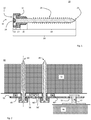
- FIG. 1 shows a sound-decoupling fastener 10 according to the present invention in a preferred embodiment as teilumantelte screw.
- the middle longitudinal axis is marked with 30.
- the head 12 shows a screw head coated on its flanks with a hard-elastic material 32, its left-facing end face 22 being uncovered.
- a force attack 28 is incorporated in the usual way.
- the sheath with the hard elastic material 32 thus covers the radially outer flanks of the head 12, the lower head region 14 and the neck region 16. Together they are referred to in this description as a cuff.
- the shaft portion 18 which is not covered with hard elastic material.
- the shank portion 18 carries a thread 24.
- the conclusion of the variant of FIG. 1 forms the tip (end portion) of the fastener, here shown as Eindringpitze. However, this is only one of several possible variants of the end section.
- the sections head 12, under head area 14, neck region 16 with adjoining shaft region 18 form the body 20 of the fastener.
- FIG. 2 The essential components are the support strip 52 and the sound-decoupling fastening elements 44, 45.
- the damping elements 48, 48 ', 48 can be added to the functional part of the description a wall or a wall element 42 fastened with the fastening elements 44, 45 clamp the support bar 52 via the damping elements 48.
- Rudimentär indicated is a piece of furniture / furniture 46, which can be hung via a connecting element 50 to the support bar 52.
Landscapes
- Engineering & Computer Science (AREA)
- General Engineering & Computer Science (AREA)
- Mechanical Engineering (AREA)
- Connection Of Plates (AREA)
- Food-Manufacturing Devices (AREA)
Abstract
Description
- Die vorliegende Erfindung befasst sich mit einem Befestigungselement, insbesondere einer Schraube, deren spezifische Auslegung eine schallentkoppelnde Wirkung zwischen den Bauteilen ermöglicht, die die Schraube verbindet.
- Im Bauwesen ist es häufig erforderlich, Einrichtungsgegenstände wie Möbel, Schränke, Regale an Wänden zu befestigen. Die lastabtragenden Verbindungselemente übertragen damit aber zwangsläufig auch Erschütterungen, die beim Belasten oder Entlasten der Einrichtungsgegenstände entstehen. Mit "schallentkoppelnd" ist daher im engeren Sinne "körperschall-entkoppelnd" gemeint auch wenn im Folgenden der Einfachheit halber von "schallentkoppelnd" die Rede sein wird.
Eine Schallentkopplung ist in vielen Fällen wünschenswert, aus Gründen der Geräuschdämmung wie auch zur Vermeidung von Beschädigungen der Wandelemente. - Es sind im Stand der Technik verschiedene Lösungen für dieses Problem der Schallentkopplung bekannt. So können elastische und/oder dämpfende Elemente vorgesehen werden, die zwischen Einrichtungsgegenstand und Wand bzw. Wandbauteil eingefügt werden. Bei einer Befestigung über Schraubverbindungen sind dämpfende Unterlagscheiben oder Kombinationen aus metallischen Unterlagscheiben mit einem flächigen, ringförmigen Feder- oder Dämpfungselementen aus Kunststoff, Gummi, Kork bekannt. Diese haben den Nachteil, dass sie jeweils separat vor der Montage dem Befestigungselement hinzugefügt werden müssen. Wird ein solches Dämpfungselement bei der Montage vergessen, falsch oder unvollständig eingesetzt, können (Körper-)Schallbrücken die Folge sein, die später sehr schwer zu entdecken und/oder zu korrigieren sind.
Ganz generell haben solche Lösungen den Nachteil, dass sie die Dämpfung im Wesentlichen nur in Richtung der Schraubenlängsachse ermöglichen. Häufig berührt aber der Schraubenschaft den Einrichtungsgegenstand bzw. dessen Befestigungspunkt und nicht allein die Unterseite des Schraubenkopfes bzw. der Unterlagscheibe. Dadurch entstehen Schallbrücken. - Es besteht von daher das Bedürfnis, ein Befestigungselement, insbesondere eine Schraube zu schaffen, die den Nachteil von Unterlagscheiben mit Dämpfungselementen vermeidet und darüber hinaus einfach in der Herstellung, der Konfektionierung und der Anwendung ist.
- Diese Aufgabe wird durch ein schallentkoppelndes Befestigungselement gelöst mit den Merkmalen des unabhängigen Anspruchs 1. Ein Aufhängesystem für Einrichtungsgegenstände, das solche schallentkoppelnde Befestigungselemente nutzt, wird ab Anspruch 9 charakterisiert. Unteransprüche beschreiben jeweils weitere Varianten und Ausführungsbeispiele.
- Ein schallentkoppelndes Befestigungselement 10 nach der vorliegenden Erfindung hat einen im Wesentlichen zylindrischen, sich entlang einer Mittenlängsachse 30 erstreckenden Körper 20. Dieser Körper 20 hat an einem Ende einen Kopf 12 mit einem Kraftangriff 28. Dieser kann wie im Stand der Technik bekannt ausgeführt sein. An den Kopf 12 schliesst sich ein Unterkopfabschnitt 14 und ein Halsbereich 16 an. Daran wiederum grenzt ein Schaftabschnitt 18, der mit einem Endabschnitt 26 abschliesst. Dieser Endabschnitt kann eine Bohrspitze sein, eine Verdrängerspitze oder eine andere, je nach vorhandenem Untergrund gewählte Spitze, die das Einformen erleichtert. Kennzeichnend ist hierbei, dass Oberflächenteile des Kopfes 12, des Unterkopfabschnitts 14 und des Halsbereichs 16 mit einem hartelastischen Material bedeckt sind, aber eine stirnseitige, vom Schaftabschnitt wegweisende Fläche des Kopfbereichs 22 unbedeckt bleibt. Mit hartelastisch ist hierbei gemeint, dass das Material elastische Eigenschaften (formreversibel) aufweist, gleichzeitig aber geeignet ist, die im Einsatz vorgesehenen Lasten zu übertragen ohne die gewünschten Eigenschaften zu verlieren. Die Materialauswahl erfolgt so, dass das Material im verbauten Zustand (also unter Vorspannung) die körperschalldämpfende Wirkung entfalten kann. Dies können beispielsweise Thermoplaste sein, insbesondere TPE (thermoplastische Elastomere), TPU (thermoplastische Urethane) und TPV (thermoplastische Vulkanisate). Ein Thermoplast (bevorzugt TPE) mit einer ShoreA Härte von ca. 60 hat im beschriebenen Einsatzfall gute Dämpfungswerte ergeben. Je nach Einsatzbereich und Lastauslegung wird eine ShoreA-Härte von 40-70, bevorzugt 45-60 angestrebt.
- Mit Blick auf
Figur 1 wird deutlich, dass die drei zumindest teilweise ummantelten Bereiche Kopf 12, Unterkopfabschnitt 14, Halsabschnitt 16 bevorzugt eine geschlossene Oberfläche zeigen. Der Halsabschnitt 16 befindet sich auf dem Schaft des Befestigungselementes, dort wird der effektive Aussendurchmesser wegen der Ummantelung grösser sein als auf dem anschliessenden Schaftabschnitt 18, der kein hartelastisches Material aufweist. Zusammengefasst sind also am Kopf 12, im Unterkopfabschnitt 14 und im Halsbereich 16 alle radial nach aussen von der Mittelängsachse weg weisenden Oberflächenbereiche mit hartelastischem Material bedeckt und bilden somit eine Art Manschette. Auch der Kopf 12 weist am Rand eine Ummantelung auf als eine Art Flankenschutz. - Als hartelastisches Material sind dabei je nach Einsatz- und Lastprofil verschiedene Kunststoffe verwendbar, Kautschuk, Gummi oder ähnliches, sowie Kombinationen davon. Denkbar ist auch, für die verschiedenen Bereiche Kopf 12, Unterkopfabschnitt 14 und Halsbereich 16 unterschiedliche Materialien zu verwenden, also mit verschiedenen Dämpfungs-/Elastizitätseigenschaften.
- Der Kopf 12 des schallentkoppelnden Befestigungselements kann bevorzugt flanschartig ausgeführt sein und somit einen Aussendurchmesser aufweisen, der grösser als der grösste Aussendurchmesser im Schaftbereich 18 ist. Diese Ausführung ähnelt also einem Nagel- oder Schraubenkopf. Durch diese Ausführung entsteht ein Unterkopfbereich, eine Unterseite des Kopfes, die flach, das heisst eben und rechtwinklig orientiert zur Mittenlängsachse oder verkippt hierzu ausgeführt sein kann (also mit konischer oder kegeliger Oberfläche). Besonders bevorzugt wird auch diese Fläche mit demselben hartelastischen Material bedeckt sein. Ein solcher Unterkopfbereich 14, wie in der
Figur 1 gezeigt, weist damit eine Oberfläche im Schaftbereich auf (radial von der Achse nach aussen orientiert) wie auch eine Oberfläche deren Orientierung in Schaftlängsrichtung ist. - Der Begriff Befestigungselement wurde bewusst gewählt, weil das erfinderische Prinzip nicht auf einen Befestigertyp beschränkt ist. Ein Befestigungselement kann eine Schraube, ein Bolzen, ein Maueranker, eine Klemmvorrichtung sein. In der Ausführung als Schraube kann der Schaftabschnitt 18 einen Gewindeabschnitt 24 aufweisen.
- Die Herstellung eines erfindungsgemässen Befestigungselementes kann durch das Umspritzen einer Schraube, eines Bolzens, eines Mauerankers mit einem hartelastischen, spritzgiessfähigen Material erfolgen. Diese Vorgehensweise ist die bei weitem bevorzugte, weil sie perfekt formschlüssige Befestiger mit Manschette herzustellen vermag. Alternativ können auch vorgefertigte Formteile aufgesteckt und durch Erhitzen aufgeschrumpft, verklebt oder verschweisst werden. Wichtig ist, dass die oben beschriebene Manschette als definierte Ummantelung resultiert.
- Mit den beschriebenen schallentkoppelnden Befestigungselementen lässt sich ein Aufhängesystem 40 für Einrichtungsgegenstände 46 wie Möbel, Schränke und Regale realisieren, die an einer Wand bzw. einem Wandabschnitt 42 schallentkoppelt befestigt werden sollen. Als Zwischenelement zwischen Wand und Möbelstück fungiert eine Tragleiste 52 mit Lastaufnahmepunkten 54 für solche Einrichtungsgegenstände 46. Mit Lastaufnahmepunkt ist dabei eine Aufnahme, ein Befestigungsloch, eine Anhänge-, Einsteck- oder Ankoppelvorrichtung gemeint. Befestigungspunkte 56, 56' dienen der Aufnahme von schallentkoppelnden Befestigungselemente 44, 45 als Verbindung zur Wand. Bevorzugt sind dies Bohrungen, die auf den Durchmesser des schallentkoppelnden Befestigers im Halsbereich 16 angepasst sind. Die Verbindung soll bevorzugt formschlüssig sein.
- Die Verwendung einer Tragleiste 52 macht in mehrfacher Hinsicht Sinn. Sie ist leichter und kleiner als der Einrichtungsgegenstand selber und kann daher an der Wand leichter ausgerichtet und befestigt werden. Erst danach wird das Möbelstück 46 befestigt - lösbar eingehängt, eingeklickt oder unlösbar verschraubt oder eingerastet. Dazu kann es sinnvoll sein, am Möbelstück einen Adapter, ein passendes Verbindungselement 50 anzubringen, welches in die Tragleiste 52 eingehängt (oder anderweitig angebracht) werden kann. Dieses Verbindungselement 50 kann standardmässig bei der Herstellung des Einrichtungsgegenstandes am statisch idealen Punkt angebracht werden und erfordert damit vor Ort keinen zusätzlichen Verarbeitungsschritt.
- In einer weiter verbesserten Variante wird das Aufhängesystem 40 Dämpfungselemente 48, 48', 48" zwischen Wandabschnitt 42 und Tragleiste 52 vorsehen Damit wird ein weiteres Dämpfungselement im Aufhängesystem vorgesehen, das verhindert, dass Erschütterungen bzw. Schall von der Tragleiste 52 auf die Wand 42 übertragen werden. Diese Dämpfungselemente 48, 48', 48" können als punktuelle oder flächige Silikon- oder Gummielemente ausgeführt werden, die in einer Variante in dafür vorgesehene Bohrungen der Tragleiste eingeklipst, -geklemmt oder geklebt werden. Ein Beispiel dafür zeigt Merkmal 48'. Diese flächigen Dämpfungselemente erlauben auch evtl. Unebenheiten der Wand 42 ggü. der Tragleiste 52 auszugleichen. Die schallentkoppelnden Befestigungselemente 44, 45 klemmen die Tragleiste 52 zwischen der hartelastischen Manschette (Bereiche 12, 14, 16) und den Dämpfungselementen 48, 48', 48".
- Die Tragleiste ist somit in der beschriebenen Ausführung komplett in schall- bzw. schwingungsdämpfenden Materialien gelagert. Somit kann die Halterung des Möbelstücks 46 an der Tragleiste 52 "hart" erfolgen, sprich auf Dämpfungselemente verzichten und auch nur so viele Lastaufnahmepunkte 54 vorsehen, wie aus statischen Gründen notwendig sind. Die Lastableitung in die Wand 42 wiederum wird durch so viele schallentkoppelnde Befestigungselemente 44, 45 vorgenommen, wie dies aufgrund des Gewichts des Möbelstücks bzw. der Beschaffenheit des Untergrundes (Wand 42) erforderlich ist. Auf diese Weise kann dieses Aufhängesystem sehr präzise an verschiedene Aufgabenprofile angepasst werden.
- Eine Tragleiste 52 wird damit bevorzugt als Metallteil mit einer Vielzahl von Bohrungen bzw. Aussparungen (Befestigungspunkte 56, 56', Lastaufnahmepunkt(e) 54) ausgeführt. Sie kann günstig als Stanzteil oder als Stanzbiegeteil ausgeführt werden. Falze können als Versteifungselemente vorgesehen werden. Eine Oberflächenbehandlung (Verzinken, Lackieren) kann zur Erhöhung von Korrosionsschutz oder als Markierung vorgesehen werden.
- Das vorhin erwähnte Verbindungselement 50, das bevorzugt am Möbelstück / Einrichtungsgegenstand 46 vormontiert wird, kann bevorzugt als Einhängeelement ausgeführt werden. Als Ausführungsbeispiel kann die in
Figur 2 gezeigte Form eines Dornes oder Zapfens mit einem Endflansch angeführt werden. Als Material findet bevorzugt Metall Verwendung. Die Herstellung kann als Formteil, Pressteil oder Drehteil erfolgen. Die Grösse und Auslegung orientiert sich an den statischen Anforderungen und kann vom Fachmann im Rahmen seiner Kenntnisse vorgenommen werden. -
-
Figur 1 zeigt einen Längsschnitt durch ein schallentkoppelndes Befestigungselement gemäss der vorliegenden Erfindung. -
Figur 2 zeigt schematisch im horizontalen Querschnitt ein Aufhängesystem für Möbelstücke mit ein schallentkoppelnden Befestigungselementen gemäss der vorliegenden Erfindung. -
Figur 1 zeigt ein schallentkoppelndes Befestigungselement 10 gemäss der vorliegenden Erfindung in einer bevorzugten Ausführung als teilummantelte Schraube. Die Mittenlängsachse ist mit 30 markiert. Am Kopf 12 ist ein an seinen Flanken mit einem hartelastischen Material 32 ummantelter Schraubenkopf gezeigt, seine nach links weisende Stirnfläche 22 ist unbedeckt. In den Kopf ist in üblicher Weise ein Kraftangriff 28 eingearbeitet. - Die Ummantelung mit dem hartelastischen Material 32 bedeckt also die radial aussenliegenden Flanken des Kopfes 12, des Unterkopfbereichs 14 und des Halsbereichs 16. Zusammen werden sie in dieser Beschreibung als Manschette bezeichnet. Entlang der Längsachse 30 schliesst sich der Schaftabschnitt 18 an, der nicht mit hartelastischem Material bedeckt ist. Er kann jedoch in bekannter Weise mit anderen funktionellen Beschichtungen versehen werden, wie Lacken, Gleitschichten, Härteüberzügen o.ä., die das Einformen und Kennzeichnung (Farbkodierung) erleichtern können. Im gezeigten Beispiel trägt der Schaftabschnitt 18 ein Gewinde 24. Den Abschluss der gezeigten Variante von
Figur 1 bildet die Spitze (Endbereich) des Befestigers, hier als Eindringspitze dargestellt. Dies ist jedoch nur eine von mehreren möglichen Ausführungsvarianten des Endabschnittes. Die Abschnitte Kopf 12, Unterkopfbereich 14, Halsbereich 16 mit anschliessendem Schaftbereich 18 bilden den Körper 20 des Befestigers. -
Figur 2 zeigt ein erfindungsgemässes Aufhängesystem 40. Dessen wesentliche Bestandteile sind die Tragleiste 52 und die schallentkoppelnden Befestigungselemente 44, 45. Ergänzend können hinzu kommen die Dämpfungselemente 48, 48', 48", wir im funktionellen Teil der Beschreibung ausgeführt. Die Einbausituation zeigt die Tragleiste 52 an einer Wand bzw. einem Wandelement 42 befestigt wobei die Befestigungselemente 44, 45 die Tragleiste 52 via die Dämpfungselemente 48 klemmen. Rudimentär angedeutet ist ein Möbelstück / Einrichtungsgegenstand 46, der via ein Verbindungselement 50 an die Tragleiste 52 gehängt werden kann. - Die in der vorstehenden Beschreibung, in den Zeichnungen sowie in den Ansprüchen offenbarten Merkmale der Erfindung können sowohl einzeln als auch in beliebiger, jedoch technisch sinnvoller bzw. vorteilhafter Kombination für die Verwirklichung der Erfindung wesentlich sein. Eine nicht-explizite Darstellung einer Kombination von Merkmalen bedeutet nicht, dass eine solche Kombination nicht sinnvoll oder nicht möglich ist.
Claims (13)
- Ein köperschallentkoppelndes Befestigungselement (10) mit einem im Wesentlichen zylindrischen, sich entlang einer Mittenlängsachse (30) erstreckenden Körper (20), wobei der Körper an einem Ende einen Kopf (12) mit einem Kraftangriff (28) umfasst, an den sich ein Unterkopfabschnitt (14) und ein Halsbereich (16) anschliesst sowie ein Schaftabschnitt (18), der mit einem Endabschnitt (26) abschliesst, dadurch gekennzeichnet, dass Oberflächenteile des Kopfes (12), des Unterkopfabschnitts (14) und des Halsbereichs (16) mit einem hartelastischen Material (32) bedeckt sind, aber eine stirnseitige, vom Schaftabschnitt wegweisende Fläche des Kopfbereichs (22) unbedeckt bleibt.
- Befestigungselement nach Anspruch 1, dadurch gekennzeichnet, dass der Schaftabschnitt (18) nicht von hartelastischem Material bedeckt ist.
- Befestigungselement nach Anspruch 1-2, dadurch gekennzeichnet, dass am Kopf (12), im Unterkopfabschnitt (14) und im Halsbereich (16) alle radial nach aussen von der Mittelängsachse (30) weg weisenden Oberflächenbereiche mit hartelastischem Material (32) bedeckt sind.
- Befestigungselement nach Anspruch 1-3, dadurch gekennzeichnet, dass der Kopf (12) flanschartig ausgeführt ist und einen Aussendurchmesser aufweist, der grösser als der grösste Aussendurchmesser im Schaftbereich (18) ist.
- Befestigungselement nach Anspruch 1-4, dadurch gekennzeichnet, dass die in Richtung des Schaftabschnittes (18) orientierte Unterseite des Kopfes (12) ebenfalls mit hartelastischem Material bedeckt ist.
- Befestigungselement nach Anspruch 1-5, dadurch gekennzeichnet, dass das Befestigungselement eine Schraube, ein Bolzen, ein Maueranker, eine Klemmvorrichtung ist.
- Befestigungselement nach Anspruch 1-6, dadurch gekennzeichnet, dass der Schaftabschnitt (18) einen Gewindeabschnitt (24) aufweist.
- Befestigungselement nach Anspruch 1-7, dadurch gekennzeichnet, dass das hartelastische Material ein Thermoplast ist, insbesondere ein thermoplastisches Elastomer, Urethan und Vulkanisat (TPE, TPU, TPV).
- Befestigungselement nach Anspruch 8, dadurch gekennzeichnet, dass das hartelastische Material ein Thermoplast ist, dessen ShoreA Härte zwischen 40 und 70 (beide Werte incl.) liegt.
- Befestigungselement nach Anspruch 9, dadurch gekennzeichnet, dass das hartelastische Material ein Thermoplast ist, dessen ShoreA Härte zwischen 45 und 60 (beide Werte incl.) liegt.
- Aufhängesystem (40) für Einrichtungsgegenstände (46) wie Möbel, Schränke und Regale an einem Wandabschnitt (42), umfassend eine Tragleiste (52) mit Lastaufnahmepunkten (54) für solche Einrichtungsgegenstände (46) und Befestigungspunkte (56, 56') für körperschallentkoppelnde Befestigungselemente (44, 45) gemäss Anspruch 1 bis 10.
- Aufhängesystem (40) nach Anspruch 10, dadurch gekennzeichnet, dass Dämpfungselemente (48, 48', 48") zwischen Wandabschnitt (42) und Tragleiste (52) vorgesehen sind, welche durch die körperschallentkoppelnden Befestigungselemente (44, 45) geklemmt werden.
- Aufhängesystem (40) nach Anspruch 10-11, dadurch gekennzeichnet, dass die Einrichtungsgegenstände (46) mit Hilfe eines Verbindungselementes (50) in die Tragleiste (52) einhängbar sind.
Priority Applications (2)
| Application Number | Priority Date | Filing Date | Title |
|---|---|---|---|
| EP23166183.6A EP4242477A3 (de) | 2018-05-22 | 2018-05-22 | Körperschallentkoppelndes befestigungselement und aufhängesystem mit einem solchen befestigungselement |
| EP18173475.7A EP3572678B1 (de) | 2018-05-22 | 2018-05-22 | Körperschallentkoppelndes befestigungselement und aufhängesystem mit einem solchen befestigungselement |
Applications Claiming Priority (1)
| Application Number | Priority Date | Filing Date | Title |
|---|---|---|---|
| EP18173475.7A EP3572678B1 (de) | 2018-05-22 | 2018-05-22 | Körperschallentkoppelndes befestigungselement und aufhängesystem mit einem solchen befestigungselement |
Related Child Applications (1)
| Application Number | Title | Priority Date | Filing Date |
|---|---|---|---|
| EP23166183.6A Division EP4242477A3 (de) | 2018-05-22 | 2018-05-22 | Körperschallentkoppelndes befestigungselement und aufhängesystem mit einem solchen befestigungselement |
Publications (2)
| Publication Number | Publication Date |
|---|---|
| EP3572678A1 true EP3572678A1 (de) | 2019-11-27 |
| EP3572678B1 EP3572678B1 (de) | 2023-04-05 |
Family
ID=62235817
Family Applications (2)
| Application Number | Title | Priority Date | Filing Date |
|---|---|---|---|
| EP18173475.7A Active EP3572678B1 (de) | 2018-05-22 | 2018-05-22 | Körperschallentkoppelndes befestigungselement und aufhängesystem mit einem solchen befestigungselement |
| EP23166183.6A Withdrawn EP4242477A3 (de) | 2018-05-22 | 2018-05-22 | Körperschallentkoppelndes befestigungselement und aufhängesystem mit einem solchen befestigungselement |
Family Applications After (1)
| Application Number | Title | Priority Date | Filing Date |
|---|---|---|---|
| EP23166183.6A Withdrawn EP4242477A3 (de) | 2018-05-22 | 2018-05-22 | Körperschallentkoppelndes befestigungselement und aufhängesystem mit einem solchen befestigungselement |
Country Status (1)
| Country | Link |
|---|---|
| EP (2) | EP3572678B1 (de) |
Citations (2)
| Publication number | Priority date | Publication date | Assignee | Title |
|---|---|---|---|---|
| JPH0725321U (ja) * | 1993-10-20 | 1995-05-12 | 株式会社テクノテック | 防水パン固定用ねじ |
| JPH09324811A (ja) * | 1996-06-05 | 1997-12-16 | I K G:Kk | 釘及びねじ |
-
2018
- 2018-05-22 EP EP18173475.7A patent/EP3572678B1/de active Active
- 2018-05-22 EP EP23166183.6A patent/EP4242477A3/de not_active Withdrawn
Patent Citations (2)
| Publication number | Priority date | Publication date | Assignee | Title |
|---|---|---|---|---|
| JPH0725321U (ja) * | 1993-10-20 | 1995-05-12 | 株式会社テクノテック | 防水パン固定用ねじ |
| JPH09324811A (ja) * | 1996-06-05 | 1997-12-16 | I K G:Kk | 釘及びねじ |
Also Published As
| Publication number | Publication date |
|---|---|
| EP3572678B1 (de) | 2023-04-05 |
| EP4242477A2 (de) | 2023-09-13 |
| EP4242477A3 (de) | 2023-11-29 |
Similar Documents
| Publication | Publication Date | Title |
|---|---|---|
| DE69307077T2 (de) | Kugelgelenk und Herstellungsverfahren dafür | |
| DE102007037242B4 (de) | Befestigungseinrichtung mit Toleranzausgleich | |
| DE60311732T2 (de) | Mit einer Zierkappe versehene Radmutter oder -bolzen | |
| DE202006012493U1 (de) | Befestigungseinrichtung mit Toleranzausgleich | |
| EP3526476B1 (de) | Clip mit schwimmender lagerung | |
| WO2009030480A2 (de) | Befestiger | |
| DE2348710C2 (de) | Dübel zur Befestigung eines Gegenstandes an einem Wandungsteil | |
| EP1588975B1 (de) | Abhängeelement | |
| EP1977120A1 (de) | Kopf einer senkschraube | |
| EP0952053A2 (de) | Vorrichtung zur Befestigung einer Wischanlage an einem Fahrzeug | |
| DE10253448B4 (de) | Gewindeeinsatz | |
| DE102009024264A1 (de) | Befestigungselement, insbesondere Mutter | |
| WO2008020017A1 (de) | Befestigungsclip | |
| DE102013004392A1 (de) | Tülle und Befestigungselement zum Befestigen einer Materialschicht | |
| EP1862356B1 (de) | Befestigungsclip | |
| DE202005021528U1 (de) | Montage- und Befestigereinheit | |
| EP3221598B1 (de) | Verformbarer körper sowie system umfassend einen verformbaren körper und einen anti-kriech-ring | |
| DE19717446B4 (de) | Anschlußeinrichtung | |
| DE60302170T2 (de) | Drehmomentwiderstehende Halteöse für Schrauben | |
| EP1096156B1 (de) | Vormontierte Befestigungsschraube | |
| EP3572678B1 (de) | Körperschallentkoppelndes befestigungselement und aufhängesystem mit einem solchen befestigungselement | |
| DE102008001552A1 (de) | Befestigungsanordnung | |
| DE202011110934U1 (de) | Befestigungseinheit | |
| EP1279839A2 (de) | Schraubblindniet-Verbindungsanordnung | |
| DE102008010655A1 (de) | Befestigungsvorrichtung für eine Matte |
Legal Events
| Date | Code | Title | Description |
|---|---|---|---|
| PUAI | Public reference made under article 153(3) epc to a published international application that has entered the european phase |
Free format text: ORIGINAL CODE: 0009012 |
|
| STAA | Information on the status of an ep patent application or granted ep patent |
Free format text: STATUS: THE APPLICATION HAS BEEN PUBLISHED |
|
| AK | Designated contracting states |
Kind code of ref document: A1 Designated state(s): AL AT BE BG CH CY CZ DE DK EE ES FI FR GB GR HR HU IE IS IT LI LT LU LV MC MK MT NL NO PL PT RO RS SE SI SK SM TR |
|
| AX | Request for extension of the european patent |
Extension state: BA ME |
|
| STAA | Information on the status of an ep patent application or granted ep patent |
Free format text: STATUS: REQUEST FOR EXAMINATION WAS MADE |
|
| 17P | Request for examination filed |
Effective date: 20200527 |
|
| RBV | Designated contracting states (corrected) |
Designated state(s): AL AT BE BG CH CY CZ DE DK EE ES FI FR GB GR HR HU IE IS IT LI LT LU LV MC MK MT NL NO PL PT RO RS SE SI SK SM TR |
|
| STAA | Information on the status of an ep patent application or granted ep patent |
Free format text: STATUS: EXAMINATION IS IN PROGRESS |
|
| 17Q | First examination report despatched |
Effective date: 20210428 |
|
| RAP3 | Party data changed (applicant data changed or rights of an application transferred) |
Owner name: SFS GROUP INTERNATIONAL AG |
|
| GRAP | Despatch of communication of intention to grant a patent |
Free format text: ORIGINAL CODE: EPIDOSNIGR1 |
|
| STAA | Information on the status of an ep patent application or granted ep patent |
Free format text: STATUS: GRANT OF PATENT IS INTENDED |
|
| INTG | Intention to grant announced |
Effective date: 20221123 |
|
| GRAS | Grant fee paid |
Free format text: ORIGINAL CODE: EPIDOSNIGR3 |
|
| GRAA | (expected) grant |
Free format text: ORIGINAL CODE: 0009210 |
|
| STAA | Information on the status of an ep patent application or granted ep patent |
Free format text: STATUS: THE PATENT HAS BEEN GRANTED |
|
| AK | Designated contracting states |
Kind code of ref document: B1 Designated state(s): AL AT BE BG CH CY CZ DE DK EE ES FI FR GB GR HR HU IE IS IT LI LT LU LV MC MK MT NL NO PL PT RO RS SE SI SK SM TR |
|
| REG | Reference to a national code |
Ref country code: GB Ref legal event code: FG4D Free format text: NOT ENGLISH |
|
| REG | Reference to a national code |
Ref country code: DE Ref legal event code: R096 Ref document number: 502018011883 Country of ref document: DE |
|
| REG | Reference to a national code |
Ref country code: CH Ref legal event code: EP |
|
| REG | Reference to a national code |
Ref country code: AT Ref legal event code: REF Ref document number: 1558434 Country of ref document: AT Kind code of ref document: T Effective date: 20230415 |
|
| REG | Reference to a national code |
Ref country code: IE Ref legal event code: FG4D Free format text: LANGUAGE OF EP DOCUMENT: GERMAN |
|
| REG | Reference to a national code |
Ref country code: LT Ref legal event code: MG9D |
|
| P01 | Opt-out of the competence of the unified patent court (upc) registered |
Effective date: 20230622 |
|
| REG | Reference to a national code |
Ref country code: NL Ref legal event code: MP Effective date: 20230405 |
|
| PG25 | Lapsed in a contracting state [announced via postgrant information from national office to epo] |
Ref country code: NL Free format text: LAPSE BECAUSE OF FAILURE TO SUBMIT A TRANSLATION OF THE DESCRIPTION OR TO PAY THE FEE WITHIN THE PRESCRIBED TIME-LIMIT Effective date: 20230405 |
|
| PG25 | Lapsed in a contracting state [announced via postgrant information from national office to epo] |
Ref country code: SE Free format text: LAPSE BECAUSE OF FAILURE TO SUBMIT A TRANSLATION OF THE DESCRIPTION OR TO PAY THE FEE WITHIN THE PRESCRIBED TIME-LIMIT Effective date: 20230405 Ref country code: PT Free format text: LAPSE BECAUSE OF FAILURE TO SUBMIT A TRANSLATION OF THE DESCRIPTION OR TO PAY THE FEE WITHIN THE PRESCRIBED TIME-LIMIT Effective date: 20230807 Ref country code: NO Free format text: LAPSE BECAUSE OF FAILURE TO SUBMIT A TRANSLATION OF THE DESCRIPTION OR TO PAY THE FEE WITHIN THE PRESCRIBED TIME-LIMIT Effective date: 20230705 Ref country code: ES Free format text: LAPSE BECAUSE OF FAILURE TO SUBMIT A TRANSLATION OF THE DESCRIPTION OR TO PAY THE FEE WITHIN THE PRESCRIBED TIME-LIMIT Effective date: 20230405 |
|
| PG25 | Lapsed in a contracting state [announced via postgrant information from national office to epo] |
Ref country code: RS Free format text: LAPSE BECAUSE OF FAILURE TO SUBMIT A TRANSLATION OF THE DESCRIPTION OR TO PAY THE FEE WITHIN THE PRESCRIBED TIME-LIMIT Effective date: 20230405 Ref country code: PL Free format text: LAPSE BECAUSE OF FAILURE TO SUBMIT A TRANSLATION OF THE DESCRIPTION OR TO PAY THE FEE WITHIN THE PRESCRIBED TIME-LIMIT Effective date: 20230405 Ref country code: LV Free format text: LAPSE BECAUSE OF FAILURE TO SUBMIT A TRANSLATION OF THE DESCRIPTION OR TO PAY THE FEE WITHIN THE PRESCRIBED TIME-LIMIT Effective date: 20230405 Ref country code: LT Free format text: LAPSE BECAUSE OF FAILURE TO SUBMIT A TRANSLATION OF THE DESCRIPTION OR TO PAY THE FEE WITHIN THE PRESCRIBED TIME-LIMIT Effective date: 20230405 Ref country code: IS Free format text: LAPSE BECAUSE OF FAILURE TO SUBMIT A TRANSLATION OF THE DESCRIPTION OR TO PAY THE FEE WITHIN THE PRESCRIBED TIME-LIMIT Effective date: 20230805 Ref country code: HR Free format text: LAPSE BECAUSE OF FAILURE TO SUBMIT A TRANSLATION OF THE DESCRIPTION OR TO PAY THE FEE WITHIN THE PRESCRIBED TIME-LIMIT Effective date: 20230405 Ref country code: GR Free format text: LAPSE BECAUSE OF FAILURE TO SUBMIT A TRANSLATION OF THE DESCRIPTION OR TO PAY THE FEE WITHIN THE PRESCRIBED TIME-LIMIT Effective date: 20230706 Ref country code: AL Free format text: LAPSE BECAUSE OF FAILURE TO SUBMIT A TRANSLATION OF THE DESCRIPTION OR TO PAY THE FEE WITHIN THE PRESCRIBED TIME-LIMIT Effective date: 20230405 |
|
| PG25 | Lapsed in a contracting state [announced via postgrant information from national office to epo] |
Ref country code: FI Free format text: LAPSE BECAUSE OF FAILURE TO SUBMIT A TRANSLATION OF THE DESCRIPTION OR TO PAY THE FEE WITHIN THE PRESCRIBED TIME-LIMIT Effective date: 20230405 |
|
| REG | Reference to a national code |
Ref country code: DE Ref legal event code: R097 Ref document number: 502018011883 Country of ref document: DE |
|
| PG25 | Lapsed in a contracting state [announced via postgrant information from national office to epo] |
Ref country code: SK Free format text: LAPSE BECAUSE OF FAILURE TO SUBMIT A TRANSLATION OF THE DESCRIPTION OR TO PAY THE FEE WITHIN THE PRESCRIBED TIME-LIMIT Effective date: 20230405 |
|
| PG25 | Lapsed in a contracting state [announced via postgrant information from national office to epo] |
Ref country code: MC Free format text: LAPSE BECAUSE OF FAILURE TO SUBMIT A TRANSLATION OF THE DESCRIPTION OR TO PAY THE FEE WITHIN THE PRESCRIBED TIME-LIMIT Effective date: 20230405 |
|
| REG | Reference to a national code |
Ref country code: BE Ref legal event code: MM Effective date: 20230531 |
|
| PG25 | Lapsed in a contracting state [announced via postgrant information from national office to epo] |
Ref country code: SM Free format text: LAPSE BECAUSE OF FAILURE TO SUBMIT A TRANSLATION OF THE DESCRIPTION OR TO PAY THE FEE WITHIN THE PRESCRIBED TIME-LIMIT Effective date: 20230405 Ref country code: SK Free format text: LAPSE BECAUSE OF FAILURE TO SUBMIT A TRANSLATION OF THE DESCRIPTION OR TO PAY THE FEE WITHIN THE PRESCRIBED TIME-LIMIT Effective date: 20230405 Ref country code: RO Free format text: LAPSE BECAUSE OF FAILURE TO SUBMIT A TRANSLATION OF THE DESCRIPTION OR TO PAY THE FEE WITHIN THE PRESCRIBED TIME-LIMIT Effective date: 20230405 Ref country code: MC Free format text: LAPSE BECAUSE OF FAILURE TO SUBMIT A TRANSLATION OF THE DESCRIPTION OR TO PAY THE FEE WITHIN THE PRESCRIBED TIME-LIMIT Effective date: 20230405 Ref country code: LU Free format text: LAPSE BECAUSE OF NON-PAYMENT OF DUE FEES Effective date: 20230522 Ref country code: EE Free format text: LAPSE BECAUSE OF FAILURE TO SUBMIT A TRANSLATION OF THE DESCRIPTION OR TO PAY THE FEE WITHIN THE PRESCRIBED TIME-LIMIT Effective date: 20230405 Ref country code: DK Free format text: LAPSE BECAUSE OF FAILURE TO SUBMIT A TRANSLATION OF THE DESCRIPTION OR TO PAY THE FEE WITHIN THE PRESCRIBED TIME-LIMIT Effective date: 20230405 Ref country code: CZ Free format text: LAPSE BECAUSE OF FAILURE TO SUBMIT A TRANSLATION OF THE DESCRIPTION OR TO PAY THE FEE WITHIN THE PRESCRIBED TIME-LIMIT Effective date: 20230405 |
|
| PLBE | No opposition filed within time limit |
Free format text: ORIGINAL CODE: 0009261 |
|
| STAA | Information on the status of an ep patent application or granted ep patent |
Free format text: STATUS: NO OPPOSITION FILED WITHIN TIME LIMIT |
|
| REG | Reference to a national code |
Ref country code: IE Ref legal event code: MM4A |
|
| 26N | No opposition filed |
Effective date: 20240108 |
|
| GBPC | Gb: european patent ceased through non-payment of renewal fee |
Effective date: 20230705 |
|
| PG25 | Lapsed in a contracting state [announced via postgrant information from national office to epo] |
Ref country code: IE Free format text: LAPSE BECAUSE OF NON-PAYMENT OF DUE FEES Effective date: 20230522 |
|
| PG25 | Lapsed in a contracting state [announced via postgrant information from national office to epo] |
Ref country code: IE Free format text: LAPSE BECAUSE OF NON-PAYMENT OF DUE FEES Effective date: 20230522 Ref country code: GB Free format text: LAPSE BECAUSE OF NON-PAYMENT OF DUE FEES Effective date: 20230705 |
|
| PG25 | Lapsed in a contracting state [announced via postgrant information from national office to epo] |
Ref country code: SI Free format text: LAPSE BECAUSE OF FAILURE TO SUBMIT A TRANSLATION OF THE DESCRIPTION OR TO PAY THE FEE WITHIN THE PRESCRIBED TIME-LIMIT Effective date: 20230405 |
|
| PG25 | Lapsed in a contracting state [announced via postgrant information from national office to epo] |
Ref country code: SI Free format text: LAPSE BECAUSE OF FAILURE TO SUBMIT A TRANSLATION OF THE DESCRIPTION OR TO PAY THE FEE WITHIN THE PRESCRIBED TIME-LIMIT Effective date: 20230405 Ref country code: BE Free format text: LAPSE BECAUSE OF NON-PAYMENT OF DUE FEES Effective date: 20230531 |
|
| PG25 | Lapsed in a contracting state [announced via postgrant information from national office to epo] |
Ref country code: BG Free format text: LAPSE BECAUSE OF FAILURE TO SUBMIT A TRANSLATION OF THE DESCRIPTION OR TO PAY THE FEE WITHIN THE PRESCRIBED TIME-LIMIT Effective date: 20230405 |
|
| PG25 | Lapsed in a contracting state [announced via postgrant information from national office to epo] |
Ref country code: BG Free format text: LAPSE BECAUSE OF FAILURE TO SUBMIT A TRANSLATION OF THE DESCRIPTION OR TO PAY THE FEE WITHIN THE PRESCRIBED TIME-LIMIT Effective date: 20230405 |
|
| PGFP | Annual fee paid to national office [announced via postgrant information from national office to epo] |
Ref country code: DE Payment date: 20250519 Year of fee payment: 8 |
|
| PGFP | Annual fee paid to national office [announced via postgrant information from national office to epo] |
Ref country code: IT Payment date: 20250530 Year of fee payment: 8 |
|
| PGFP | Annual fee paid to national office [announced via postgrant information from national office to epo] |
Ref country code: FR Payment date: 20250523 Year of fee payment: 8 |
|
| PGFP | Annual fee paid to national office [announced via postgrant information from national office to epo] |
Ref country code: CH Payment date: 20250601 Year of fee payment: 8 |
|
| PGFP | Annual fee paid to national office [announced via postgrant information from national office to epo] |
Ref country code: AT Payment date: 20250519 Year of fee payment: 8 |
|
| PG25 | Lapsed in a contracting state [announced via postgrant information from national office to epo] |
Ref country code: CY Free format text: LAPSE BECAUSE OF FAILURE TO SUBMIT A TRANSLATION OF THE DESCRIPTION OR TO PAY THE FEE WITHIN THE PRESCRIBED TIME-LIMIT; INVALID AB INITIO Effective date: 20180522 |
|
| PG25 | Lapsed in a contracting state [announced via postgrant information from national office to epo] |
Ref country code: HU Free format text: LAPSE BECAUSE OF FAILURE TO SUBMIT A TRANSLATION OF THE DESCRIPTION OR TO PAY THE FEE WITHIN THE PRESCRIBED TIME-LIMIT; INVALID AB INITIO Effective date: 20180522 |
|
| PG25 | Lapsed in a contracting state [announced via postgrant information from national office to epo] |
Ref country code: TR Free format text: LAPSE BECAUSE OF FAILURE TO SUBMIT A TRANSLATION OF THE DESCRIPTION OR TO PAY THE FEE WITHIN THE PRESCRIBED TIME-LIMIT Effective date: 20230405 |