EP3572663A1 - Kraftstofffilter zum reinigen von kraftstoff für eine brennkraftmaschine - Google Patents
Kraftstofffilter zum reinigen von kraftstoff für eine brennkraftmaschine Download PDFInfo
- Publication number
- EP3572663A1 EP3572663A1 EP19175381.3A EP19175381A EP3572663A1 EP 3572663 A1 EP3572663 A1 EP 3572663A1 EP 19175381 A EP19175381 A EP 19175381A EP 3572663 A1 EP3572663 A1 EP 3572663A1
- Authority
- EP
- European Patent Office
- Prior art keywords
- fuel
- water
- filter
- jet pump
- suction jet
- Prior art date
- Legal status (The legal status is an assumption and is not a legal conclusion. Google has not performed a legal analysis and makes no representation as to the accuracy of the status listed.)
- Granted
Links
Images
Classifications
-
- B—PERFORMING OPERATIONS; TRANSPORTING
- B01—PHYSICAL OR CHEMICAL PROCESSES OR APPARATUS IN GENERAL
- B01D—SEPARATION
- B01D29/00—Filters with filtering elements stationary during filtration, e.g. pressure or suction filters, not covered by groups B01D24/00 - B01D27/00; Filtering elements therefor
- B01D29/88—Filters with filtering elements stationary during filtration, e.g. pressure or suction filters, not covered by groups B01D24/00 - B01D27/00; Filtering elements therefor having feed or discharge devices
- B01D29/94—Filters with filtering elements stationary during filtration, e.g. pressure or suction filters, not covered by groups B01D24/00 - B01D27/00; Filtering elements therefor having feed or discharge devices for discharging the filter cake, e.g. chutes
- B01D29/945—Filters with filtering elements stationary during filtration, e.g. pressure or suction filters, not covered by groups B01D24/00 - B01D27/00; Filtering elements therefor having feed or discharge devices for discharging the filter cake, e.g. chutes for continuously discharging concentrated liquid
-
- F—MECHANICAL ENGINEERING; LIGHTING; HEATING; WEAPONS; BLASTING
- F02—COMBUSTION ENGINES; HOT-GAS OR COMBUSTION-PRODUCT ENGINE PLANTS
- F02M—SUPPLYING COMBUSTION ENGINES IN GENERAL WITH COMBUSTIBLE MIXTURES OR CONSTITUENTS THEREOF
- F02M37/00—Apparatus or systems for feeding liquid fuel from storage containers to carburettors or fuel-injection apparatus; Arrangements for purifying liquid fuel specially adapted for, or arranged on, internal-combustion engines
- F02M37/22—Arrangements for purifying liquid fuel specially adapted for, or arranged on, internal-combustion engines, e.g. arrangements in the feeding system
- F02M37/24—Arrangements for purifying liquid fuel specially adapted for, or arranged on, internal-combustion engines, e.g. arrangements in the feeding system characterised by water separating means
-
- B—PERFORMING OPERATIONS; TRANSPORTING
- B01—PHYSICAL OR CHEMICAL PROCESSES OR APPARATUS IN GENERAL
- B01D—SEPARATION
- B01D29/00—Filters with filtering elements stationary during filtration, e.g. pressure or suction filters, not covered by groups B01D24/00 - B01D27/00; Filtering elements therefor
- B01D29/96—Filters with filtering elements stationary during filtration, e.g. pressure or suction filters, not covered by groups B01D24/00 - B01D27/00; Filtering elements therefor in which the filtering elements are moved between filtering operations; Particular measures for removing or replacing the filtering elements; Transport systems for filters
-
- B—PERFORMING OPERATIONS; TRANSPORTING
- B01—PHYSICAL OR CHEMICAL PROCESSES OR APPARATUS IN GENERAL
- B01D—SEPARATION
- B01D36/00—Filter circuits or combinations of filters with other separating devices
- B01D36/003—Filters in combination with devices for the removal of liquids
-
- F—MECHANICAL ENGINEERING; LIGHTING; HEATING; WEAPONS; BLASTING
- F02—COMBUSTION ENGINES; HOT-GAS OR COMBUSTION-PRODUCT ENGINE PLANTS
- F02M—SUPPLYING COMBUSTION ENGINES IN GENERAL WITH COMBUSTIBLE MIXTURES OR CONSTITUENTS THEREOF
- F02M37/00—Apparatus or systems for feeding liquid fuel from storage containers to carburettors or fuel-injection apparatus; Arrangements for purifying liquid fuel specially adapted for, or arranged on, internal-combustion engines
- F02M37/0047—Layout or arrangement of systems for feeding fuel
- F02M37/0052—Details on the fuel return circuit; Arrangement of pressure regulators
-
- F—MECHANICAL ENGINEERING; LIGHTING; HEATING; WEAPONS; BLASTING
- F02—COMBUSTION ENGINES; HOT-GAS OR COMBUSTION-PRODUCT ENGINE PLANTS
- F02M—SUPPLYING COMBUSTION ENGINES IN GENERAL WITH COMBUSTIBLE MIXTURES OR CONSTITUENTS THEREOF
- F02M37/00—Apparatus or systems for feeding liquid fuel from storage containers to carburettors or fuel-injection apparatus; Arrangements for purifying liquid fuel specially adapted for, or arranged on, internal-combustion engines
- F02M37/04—Feeding by means of driven pumps
-
- F—MECHANICAL ENGINEERING; LIGHTING; HEATING; WEAPONS; BLASTING
- F02—COMBUSTION ENGINES; HOT-GAS OR COMBUSTION-PRODUCT ENGINE PLANTS
- F02M—SUPPLYING COMBUSTION ENGINES IN GENERAL WITH COMBUSTIBLE MIXTURES OR CONSTITUENTS THEREOF
- F02M37/00—Apparatus or systems for feeding liquid fuel from storage containers to carburettors or fuel-injection apparatus; Arrangements for purifying liquid fuel specially adapted for, or arranged on, internal-combustion engines
- F02M37/22—Arrangements for purifying liquid fuel specially adapted for, or arranged on, internal-combustion engines, e.g. arrangements in the feeding system
- F02M37/24—Arrangements for purifying liquid fuel specially adapted for, or arranged on, internal-combustion engines, e.g. arrangements in the feeding system characterised by water separating means
- F02M37/26—Arrangements for purifying liquid fuel specially adapted for, or arranged on, internal-combustion engines, e.g. arrangements in the feeding system characterised by water separating means with water detection means
-
- F—MECHANICAL ENGINEERING; LIGHTING; HEATING; WEAPONS; BLASTING
- F02—COMBUSTION ENGINES; HOT-GAS OR COMBUSTION-PRODUCT ENGINE PLANTS
- F02M—SUPPLYING COMBUSTION ENGINES IN GENERAL WITH COMBUSTIBLE MIXTURES OR CONSTITUENTS THEREOF
- F02M37/00—Apparatus or systems for feeding liquid fuel from storage containers to carburettors or fuel-injection apparatus; Arrangements for purifying liquid fuel specially adapted for, or arranged on, internal-combustion engines
- F02M37/22—Arrangements for purifying liquid fuel specially adapted for, or arranged on, internal-combustion engines, e.g. arrangements in the feeding system
- F02M37/32—Arrangements for purifying liquid fuel specially adapted for, or arranged on, internal-combustion engines, e.g. arrangements in the feeding system characterised by filters or filter arrangements
-
- F—MECHANICAL ENGINEERING; LIGHTING; HEATING; WEAPONS; BLASTING
- F02—COMBUSTION ENGINES; HOT-GAS OR COMBUSTION-PRODUCT ENGINE PLANTS
- F02M—SUPPLYING COMBUSTION ENGINES IN GENERAL WITH COMBUSTIBLE MIXTURES OR CONSTITUENTS THEREOF
- F02M37/00—Apparatus or systems for feeding liquid fuel from storage containers to carburettors or fuel-injection apparatus; Arrangements for purifying liquid fuel specially adapted for, or arranged on, internal-combustion engines
- F02M37/22—Arrangements for purifying liquid fuel specially adapted for, or arranged on, internal-combustion engines, e.g. arrangements in the feeding system
- F02M37/32—Arrangements for purifying liquid fuel specially adapted for, or arranged on, internal-combustion engines, e.g. arrangements in the feeding system characterised by filters or filter arrangements
- F02M37/44—Filters structurally associated with pumps
-
- F—MECHANICAL ENGINEERING; LIGHTING; HEATING; WEAPONS; BLASTING
- F02—COMBUSTION ENGINES; HOT-GAS OR COMBUSTION-PRODUCT ENGINE PLANTS
- F02M—SUPPLYING COMBUSTION ENGINES IN GENERAL WITH COMBUSTIBLE MIXTURES OR CONSTITUENTS THEREOF
- F02M37/00—Apparatus or systems for feeding liquid fuel from storage containers to carburettors or fuel-injection apparatus; Arrangements for purifying liquid fuel specially adapted for, or arranged on, internal-combustion engines
- F02M37/22—Arrangements for purifying liquid fuel specially adapted for, or arranged on, internal-combustion engines, e.g. arrangements in the feeding system
- F02M37/54—Arrangements for purifying liquid fuel specially adapted for, or arranged on, internal-combustion engines, e.g. arrangements in the feeding system characterised by air purging means
-
- B—PERFORMING OPERATIONS; TRANSPORTING
- B01—PHYSICAL OR CHEMICAL PROCESSES OR APPARATUS IN GENERAL
- B01D—SEPARATION
- B01D2201/00—Details relating to filtering apparatus
- B01D2201/20—Pressure-related systems for filters
- B01D2201/204—Systems for applying vacuum to filters
- B01D2201/208—Systems for applying vacuum to filters by venturi systems
-
- B—PERFORMING OPERATIONS; TRANSPORTING
- B01—PHYSICAL OR CHEMICAL PROCESSES OR APPARATUS IN GENERAL
- B01D—SEPARATION
- B01D29/00—Filters with filtering elements stationary during filtration, e.g. pressure or suction filters, not covered by groups B01D24/00 - B01D27/00; Filtering elements therefor
- B01D29/50—Filters with filtering elements stationary during filtration, e.g. pressure or suction filters, not covered by groups B01D24/00 - B01D27/00; Filtering elements therefor with multiple filtering elements, characterised by their mutual disposition
- B01D29/56—Filters with filtering elements stationary during filtration, e.g. pressure or suction filters, not covered by groups B01D24/00 - B01D27/00; Filtering elements therefor with multiple filtering elements, characterised by their mutual disposition in series connection
-
- F—MECHANICAL ENGINEERING; LIGHTING; HEATING; WEAPONS; BLASTING
- F02—COMBUSTION ENGINES; HOT-GAS OR COMBUSTION-PRODUCT ENGINE PLANTS
- F02M—SUPPLYING COMBUSTION ENGINES IN GENERAL WITH COMBUSTIBLE MIXTURES OR CONSTITUENTS THEREOF
- F02M37/00—Apparatus or systems for feeding liquid fuel from storage containers to carburettors or fuel-injection apparatus; Arrangements for purifying liquid fuel specially adapted for, or arranged on, internal-combustion engines
- F02M37/02—Feeding by means of suction apparatus, e.g. by air flow through carburettors
- F02M37/025—Feeding by means of a liquid fuel-driven jet pump
Definitions
- the invention relates to a fuel filter for cleaning fuel for an internal combustion engine.
- the invention further relates to an internal combustion engine with such a fuel filter and a motor vehicle with such an internal combustion engine.
- Complex fuel filters are often constructed in two stages and comprise a prefilter and a main filter with an intermediate conveyor, typically in the form of a suitable fuel pump.
- the fuel filter usually comprises a water separator for separating the water contained in the fuel and - as part of the water separator - a water collection chamber for collecting the separated water.
- the water collection chamber may have a return line back into the fuel tank in certain filter systems.
- a useful application for the return line from the water collection room to the tank is e.g. also a fill level limit for water in the water collection room.
- a pressure gradient must be present for the return line. In the case of fuel filters operated on the intake side, the pressure gradient in the direction of the return line in the filter must first be generated.
- the basic idea of the invention is therefore to equip a fuel filter with a suction jet pump, which is fluidically connected to the water collection chamber of the water separator, so that by means of the suction jet pump water and fuel from the water collection chamber in which a negative pressure acts, can be discharged into the return line, in the higher pressure than in the water collection chamber acts.
- the suction jet pump the pumping action required for this purpose is provided by means of a propellant medium from the pressure-side main filter, which sucks in the water or fuel from the water collection chamber by pulse exchange and thus promotes.
- the pressure gradient required for the transport of water or fuel from the water collecting space can therefore be generated in a simple manner, without having to provide an external drive for driving the pump from the outside.
- a fuel filter according to the invention for purifying fuel for an internal combustion engine comprises a main filter and a pre-filter arranged upstream of the main filter.
- the pre-filter and the main filter can thus be successively flowed through by the fuel.
- the pre-filter includes a water separator for separating water present in the fuel.
- the water separator on a filter element, in particular in the form of a hydrophobic membrane, for separating the water from the fuel and a water collecting space for collecting the separated water.
- the pre-filter is fluidly connected by means of a conveyor with the main filter, which promotes the fuel from the pre-filter into the main filter.
- the fuel sucked out of the pre-filter flows from a suitable fuel reservoir into the pre-filter after. After flowing through the main filter, the purified fuel is available for use in the internal combustion engine.
- the fuel filter device comprises a fluid jet pump connected to the water separator, preferably with its water collecting space for discharging the water separated by the water separator or accumulated in the water collecting chamber, in particular when the water exceeds a predetermined maximum level.
- a small subset flows continuously from the pressure range of the main filter via the suction jet pump in the return line and continuously promotes water or fuel from the water collection in the negative pressure region of the prefilter in the return line.
- the water collection chamber of the prefilter is normally filled with fuel and vented. Contains the funded from the fuel reservoir shares of water, this is retained in the water, flows there in the water collection chamber and displaces there the existing fuel. The water accumulates due to the higher density of water to fuel at the bottom of the water collection chamber and gradually fills the water collection chamber. If the water collection room is filled, the water should be drained by means of a drainage option. Therefore, in a preferred embodiment, it is proposed to provide a water outlet in a lower region of the water collecting space, from which water can be discharged from the water collecting space. Alternatively or additionally, an outlet connected fluidly to the suction jet pump can be configured as an overflow, which defines a maximum possible filling level of water in the water collecting space.
- the water collection room would overflow if the water continued to be supplied, i. the further supplied water would not be retained and would be able to reach the engine together with the fuel. For this reason, the maximum level of water in the water collection room must be limited.
- Another reason for setting a maximum allowable level for water in the water collection is the risk in practice of freezing the water to ice while increasing volume.
- the fuel When freezing the water to ice must be present in the water collection volume filled with fuel volume fraction, which can be filled by the increased volume of ice, the fuel must be displaced via the inlet and outlet channels of the water collection chamber in other areas of the fuel filter. When completely filled with water container, this can burst when freezing the water.
- connection line water collection - ejector - return line is fluidically discharged at a defined level in the water collection chamber and this connection so forms an "overflow" for water.
- the water accumulates due to the difference in density to the fuel at the bottom of the housing. If further water is supplied and the level reaches the level of the discharge in the connecting line, then further water is transported with the continuous volume flow through the connecting line from the water collecting space via the suction jet pump in the return line.
- the level of discharge into the connecting pipe in the water collection room is chosen so that at this level and normal operating situations no water can get into the engine together with the fuel and that the filter housing does not burst when freezing the collected water.
- the tank thus serves as a buffer for the recycled water for a transitional period.
- a fuel take-off is provided on the main filter, which communicates fluidically with the suction jet pump.
- the fuel flowing through the fuel discharge fuel can be used as a driving medium for the ejector, so that the cost of driving the pump remains negligible. If one uses the fuel extraction channel from the main filter to the suction jet pump simultaneously as a venting channel for the fuel filter, the economic overhead is low.
- the fuel discharge communicates via the suction jet pump fluidly with an additional water separator.
- This additional water separator serves to separate the fuel acting as the driving medium from the water conveyed by the suction jet pump from the water separator or its water collecting space.
- This additional water separator may conveniently be spatially separated from the actual fuel filter be arranged, so preferably as a component in or on the tank.
- the volume of the water collection chamber could be made correspondingly small in this embodiment, and in the water collection room could be dispensed with a Wasserablassdorfkeit.
- a water separator fuel outlet is arranged in the additional water separator.
- the latter communicates fluidically with a fuel reservoir for discharging the fuel present in the additional water separator.
- the main filter may comprise a filter housing in which a filter element is arranged.
- the filter element divides the housing interior, which is bounded by the filter housing, into a raw side and a clean side.
- Said fuel discharge to the suction jet pump is carried out on the raw or on the clean side, which can be done in the same channel at a fuel takeoff on the raw side in the upper part of the filter housing the venting of the filter device.
- On the clean side of the filter a fuel outlet for discharging the purified fuel from the fuel filter into an internal combustion engine is provided.
- the filtered-out fuel can be used in the internal combustion engine.
- the amount of fuel derived by means of the suction jet pump substantially corresponds to the amount of fuel that is permanently returned to the tank for self-venting of the filter and therefore does not constitute a disadvantage.
- the water separator has a separator housing, which can flow through one of the fuel Enclosure interior limited.
- a hydrophobic membrane through which the fuel can flow is disposed in the interior of the housing for separating the water present in the fuel.
- the water collecting space is formed by a lower region of the housing interior with respect to the direction of gravity.
- the invention further relates to an internal combustion engine for a motor vehicle with cylinders, in each of which a combustion chamber is present.
- Each cylinder has at least one fuel injector for injecting fuel into the respective combustion chamber.
- the internal combustion engine includes a fuel supply for introducing the fuel into the fuel injectors.
- a fuel filter presented above is arranged upstream of the fuel feed. The advantages of the fuel filter explained above are therefore also transferred to the internal combustion engine according to the invention.
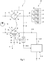
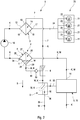
- FIG. 1 Illustrates schematically and in a circuit diagram-like representation of the structure of the invention fuel filter 1 for cleaning fuel K for an internal combustion engine. It describes the FIG. 1 a fuel filter with a water drainage option from the water collection room and FIG. 2 an advantageous development with an additional water separator, which serves to separate the fuel acting as a driving medium.
- the fuel filter 1 comprises according to FIG. 1 a main filter 3 and a pre-filter 2 arranged upstream of the main filter 3. Upstream of the prefilter 2, a fuel reservoir 9 realized as a fuel tank 10 with the fuel K to be cleaned is provided. The two filters 2, 3 are successively flowed through by the fuel K.
- the pre-filter 2 comprises a water separator 4 for separating water present in the fuel K.
- the water separator 4 has a separator housing 25 which delimits a housing interior 26 through which fuel K can flow.
- a separator housing 25 In the housing interior 26 of the water separator 4 is one of the fuel K Maschinenströmbare hydrophobic membrane 27 for separating the present in the fuel K water W arranged.
- the water separator 4 also has a water collecting space 5 for collecting the water W separated in the water separator 4.
- the pre-filter 2 is fluidically connected to the main filter 3 by means of a conveyor 18.
- the conveyor 18 conveys the fuel K from the pre-filter 2 in the main filter 3.
- the fuel filter 1 comprises a fluidly connected to the water collection chamber 5 of the water separator 4 Saugstrahlpumpe 6. By means of the suction jet pump 6, the FIG. 1 is only roughly illustrated, medium is permanently removed from the water collection chamber 5.
- the water collection chamber 5 of the water separator 4 is formed by a respect to the direction of gravity S in the lower region 28 of the housing interior 26 when the water separator 4 is in a position of use.
- an outlet 29 is provided, which communicates fluidically with the suction jet pump 6. Due to the distance of the outlet 29 to the lower lying lower end of the housing interior 26, the max. Adjust filling level for water in the water collection room. In this way, by means of the suction jet pump 6, the water W above a desired level from the water collection chamber 5 are pumped.
- a water level sensor 34 which indicates the presence of water W to the outside, for example with an electrical signal, may be disposed below the outlet 29 and thus within the maximum filling level for water W and indicate the presence of water W to the outside.
- a water drain 32 On the housing bottom of the lower portion 28 of the water collection chamber 5, a water drain 32 may be arranged to discharge water from the fuel filter 1 into the environment.
- the main filter 3 comprises a fuel discharge 7, which communicates fluidly with the suction jet pump 6.
- the fuel flowing through the fuel discharge 7 and supplied to the suction jet pump 6 fuel can serve as the driving medium for the water from the water jet separator 4 to be conveyed by the suction jet pump 6.
- the main filter 3 has an in FIG. 1 only roughly schematically illustrated filter housing 12, in which a filter element 13, preferably interchangeable, is arranged.
- the filter element 13 divides the housing interior 14 delimited by the filter housing 12 into a raw side 15 and a clean side 16.
- the suction jet pump 6 is arranged in a connecting line 7, which fluidly connects the raw side 15 of the main filter 3 with the additional water separator 8.
- the medium from this line drives the suction jet pump 6.
- the suction jet pump 6 is fluidly connected to the water collecting space 5 via a connecting line 19 and sucks the medium from the water collecting space 5.
- FIG. 1 only roughly schematically illustrated internal combustion engine 20 has, for example, four cylinders 21, in each of which a combustion chamber 22 is present.
- Each cylinder 21 has a fuel injector 23 for injecting the purified fuel K into the respective combustion chamber 22.
- the internal combustion engine 20 has a fuel supply 24 for introducing the fuel K into the fuel injectors 23.
- the fuel filter 1 according to the invention is thus arranged upstream of the fuel supply 24.
- the fuel reservoir 9 or the fuel tank 10 has a fuel outlet 11, which communicates via the pre-filter 2, the conveyor 18 and the main filter 3 with the internal combustion engine 2o.
- FIG. 2 shows a variant of the example of FIG. 1 , Corresponding FIG. 2 the fuel discharge 7 communicates fluidically via the suction jet pump 6 with an additional water separator 8 for separating the fuel acting as the driving medium from the water W conveyed by the suction jet pump from the water separator 4 or its water collection chamber 5.
- a water separator fuel discharge 30 which communicates fluidically with the fuel reservoir 9 or with the fuel tank 10 for discharging the fuel present in the water separator 4.
- a water level sensor 34 may be arranged for water and indicate the presence of water to the outside, for example by means of an electrical signal.
- a water outlet 35 may be arranged to discharge water W from the filter system to the environment.
- FIGS. 1 and FIG. 2 is in the connecting line 19 from the water collection chamber to the suction jet pump 6, a check valve 33 is provided which allows flow from the water collection chamber 5 to the suction jet pump 6 and blocked flow from the suction jet pump 6 to the water collection chamber 5.
Landscapes
- Engineering & Computer Science (AREA)
- Chemical & Material Sciences (AREA)
- Combustion & Propulsion (AREA)
- Mechanical Engineering (AREA)
- General Engineering & Computer Science (AREA)
- Chemical Kinetics & Catalysis (AREA)
- Cooling, Air Intake And Gas Exhaust, And Fuel Tank Arrangements In Propulsion Units (AREA)
- Filtration Of Liquid (AREA)
Abstract
- mit einem Hauptfilter (3) und mit einem stromauf des Hauptfilters (3) angeordneten Vorfilter (2), welche sukzessive von dem Kraftstoff (K) durchströmbar sind,
- wobei das Vorfilter (2) einen Wasserabscheider (4) zum Abscheiden von im Kraftstoff (K) vorhandenem Wasser (W) aufweist, welcher einen Wassersammelraum (5) zum Sammeln des abgeschiedenen Wassers (W) umfasst,
- wobei das Vorfilter (2) über eine Fördereinrichtung (18) fluidisch mit dem Hauptfilter (3) verbunden ist, welche den Kraftstoff vom Vorfilter in das Hauptfilter (3) fördert,
- mit einer fluidisch mit dem Wassersammelraum (5) verbundenen Saugstrahlpumpe (6) zum Abführen von Wasser (W) aus dem Wassersammelraum (5).
Description
- Die Erfindung betrifft ein Kraftstofffilter zum Reinigen von Kraftstoff für eine Brennkraftmaschine. Die Erfindung betrifft ferner eine Brennkraftmaschine mit einem solchen Kraftstofffilter sowie ein Kraftfahrzeug mit einer solchen Brennkraftmaschine.
- Komplexe Kraftstofffilter, insbesondere für Dieselkraftstoff, sind oftmals zweistufig aufgebaut und umfassen ein Vorfilter sowie ein Hauptfilter mit einer dazwischen geschalteten Fördereinrichtung, typischerweise in Form einer geeigneten Kraftstoffpumpe. Das Kraftstofffilter umfasst dabei üblicherweise einen Wasserabscheider zum Abscheiden vom im Kraftstoff enthaltenen Wasser sowie - als Teil des Wasserabscheiders - einen Wassersammelraum zum Sammeln des abgeschiedenen Wassers.
- Dabei kann der Wassersammelraum bei bestimmten Filtersystemen eine Rücklaufleitung zurück in den Kraftstofftank aufweisen. Eine sinnvolle Anwendung für die Rücklaufleitung aus dem Wassersammelraum zum Tank ist z.B. auch eine Füllstands-Begrenzung für Wasser im Wassersammelraum. Damit eine Strömung erfolgen kann, muss zur Rücklaufleitung ein Druckgefälle anstehen. Bei saugseitig betriebenen Kraftstofffiltern muss das Druckgefälle in Richtung Rücklaufleitung im Filter erst noch erzeugt werden.
- Es ist eine Aufgabe der vorliegenden Erfindung, bei der Entwicklung von Kraftstofffiltern für Brennkraftmaschinen, insbesondere für Dieselmotoren, neue Wege aufzuzeigen.
- Diese Aufgabe wird durch den Gegenstand der unabhängigen Patentansprüche gelöst. Bevorzugte Ausführungsformen sind Gegenstand der abhängigen Patentansprüche.
- Grundidee der Erfindung ist demnach, ein Kraftstofffilter mit einer Saugstrahlpumpe auszustatten, welche fluidisch mit dem Wassersammelraum des Wasserabscheiders verbunden ist, sodass mittels der Saugstrahlpumpe Wasser und Kraftstoff aus dem Wassersammelraum, in dem ein Unterdruck wirkt, in die Rücklaufleitung abgeführt werden können, in dem ein höherer Druck als im Wassersammelraum wirkt. In der Saugstrahlpumpe wird die hierfür erforderliche Pumpwirkung mit Hilfe eines Treibmediums aus dem druckseitigen Hauptfilter bereitgestellt, das durch Impulsaustausch das Wasser bzw. Kraftstoff aus dem Wassersammelraum ansaugt und somit fördert. Mithilfe der Saugstrahlpumpe kann daher auf einfache Weise das für den Transport von Wasser bzw. Kraftstoff aus dem Wassersammelraum erforderliche Druckgefälle erzeugt werden, ohne dass hierfür von außen ein externer Antrieb zum Antreiben der Pumpe bereitgestellt werden muss.
- Ein erfindungsgemäßes Kraftstofffilter zum Reinigen von Kraftstoff für eine Brennkraftmaschine umfasst ein Hauptfilter und ein stromauf des Hauptfilters angeordnetes Vorfilter. Das Vorfilter und das Hauptfilter können somit sukzessive von dem Kraftstoff durchströmt werden. Das Vorfilter umfasst einen Wasserabscheider zum Abscheiden von im Kraftstoff vorhandenem Wasser. Hierzu weist der Wasserabscheider ein Filterelement, insbesondere in Form einer hydrophoben Membran, zum Abscheiden des Wassers aus dem Kraftstoff sowie einen Wassersammelraum zum Sammeln des abgeschiedenen Wassers auf. Das Vorfilter ist mittels einer Fördereinrichtung fluidisch mit dem Hauptfilter verbunden, welche den Kraftstoff vom Vorfilter in das Hauptfilter fördert. Der aus dem Vorfilter gesaugte Kraftstoff strömt aus einem geeigneten Kraftstoff-Reservoir in das Vorfilter nach. Nach dem Durchströmen des Hauptfilters steht der gereinigte Kraftstoff zur Verwendung in der Brennkraftmaschine zur Verfügung.
- Erfindungsgemäß umfasst die Kraftstofffiltereinrichtung eine fluidisch mit dem Wasserabscheider, vorzugsweise mit dessen Wassersammelraum verbundene Saugstrahlpumpe zum Abführen des mittels des Wasserabscheiders abgeschiedenen bzw. des im Wassersammelraum angesammelten Wassers, insbesondere wenn das Wasser einen vorbestimmten maximalen Füllstand überschreitet.
- Im Betrieb des Kraftstofffilters, d.h. im Betrieb der Fördereinrichtung mit Druckaufbau im Hauptfilter, strömt kontinuierlich eine kleine Teilmenge aus dem Druckbereich des Hauptfilters über die Saugstrahlpumpe in die Rücklaufleitung ab und fördert dabei kontinuierlich Wasser bzw. Kraftstoff aus dem Wassersammelraum im Unterdruckbereich des Vorfilters in die Rücklaufleitung.
- Der Wassersammelraum des Vorfilters ist normalerweise mit Kraftstoff gefüllt und entlüftet. Enthält der aus dem Kraftstoffreservoir geförderte Kraftstoff Anteile von Wasser, wird dieses im Wasserabscheider zurückgehalten, fließt dort in den Wassersammelraum und verdrängt dort den darin vorhandenen Kraftstoff. Das Wasser sammelt sich aufgrund der höheren Dichte des Wassers zum Kraftstoff am Boden des Wassersammelraums an und füllt nach und nach den Wassersammelraum. Ist der Wassersammelraum gefüllt, sollte das Wasser mittels einer Wasserablassmöglichkeit abgelassen werden. Daher wird in einer bevorzugten Ausführungsform vorgeschlagen, in einem unteren Bereich des Wassersammelraums einen Wasserauslass vorzusehen, aus welchem Wasser aus dem Wassersammelraum abgelassen werden kann. Alternativ oder zusätzlich kann ein fluidisch mit der Saugstrahlpumpe verbundener Auslass als Überlauf ausgestaltet sein, der eine maximal mögliche Füllhöhe an Wasser im Wassersammelraum festlegt.
- Würde kein Wasser aus dem Wassersammelraum abgelassen bzw. abgeführt, würde der Wassersammelraum bei weiter zugeführtem Wasser überlaufen, d.h. das weiter zugeführtes Wasser würde nicht zurückgehalten und würde zusammen mit dem Kraftstoff zum Motor gelangen können. Aus diesem Grund muss der maximale Füllstand für Wasser im Wassersammelraum begrenzt werden.
- Ein weiterer Grund für die Festlegung eines maximal zulässigen Füllstands für Wasser im Wassersammelraum ist die in der Praxis bestehende Gefahr des Frierens des Wassers zu Eis unter Volumenzuwachs. Beim Frieren des Wassers zu Eis muss im Wassersammelraum ein mit Kraftstoff gefüllter Volumenanteil vorhanden sein, der von dem vergrößerten Volumen des Eises ausgefüllt werden kann, wobei der Kraftstoff über die Zu- und Ablaufkanäle des Wassersammelraums in andere Bereiche des Kraftstofffilters verdrängt werden können muss. Bei vollständig mit Wasser gefülltem Behältnis kann dieses beim Gefrieren des Wassers platzen.
- Da es in der Praxis nicht immer möglich ist, Wasser aus dem Wasserabscheider abzulassen, wird die maximale Füllhöhe für Wasser im Wassersammelraum bei einer bevorzugten Ausführungsform begrenzt, indem die Verbindungsleitung Wassersammelraum - Saugstrahlpumpe - Rücklaufleitung auf einem definierten Niveau im Wassersammelraum fluidisch ausgeleitet wird und diese Verbindung so einen "Überlauf" für Wasser bildet. Unterhalb der Ausleitung in die Verbindungleitung sammelt sich das Wasser wegen des Dichteunterschiedes zum Kraftstoff am Gehäuseboden an. Wird weiter Wasser zugeführt und erreicht der Füllstand das Niveau der Ausleitung in die Verbindungsleitung, dann wird weiteres Wasser mit dem kontinuierlichen Volumenstrom durch die Verbindungsleitung vom Wassersammelraum über die Saugstrahlpumpe in die Rücklaufleitung transportiert. Das Niveau der Ausleitung in die Verbindungsleitung im Wassersammelraum ist dabei so gewählt, dass bei diesem Niveau und normalem Betriebssituationen kein Wasser zusammen mit dem Kraftstoff in die Brennkraftmaschine gelangen kann und dass das Filtergehäuse beim Frieren des gesammelten Wassers nicht platzt.
- Wird Wasser aus dem Wassersammelraum über die Saugstrahlpumpe in die Rücklaufleitung transportiert, so gelangt es über die Rücklaufleitung zurück in den Tank. Der Tank dient somit für eine Übergangszeit als Puffer für das zurückgeführte Wasser.
- Gemäß einer bevorzugten Ausführungsform ist am Hauptfilter ein Kraftstoffabzug vorgesehen, der fluidisch mit der Saugstrahlpumpe kommuniziert. Auf diese Weise kann der durch den Kraftstoffabzug strömende Kraftstoff als Treibmedium für die Saugstrahlpumpe verwendet werden, sodass der Aufwand für den Antrieb der Pumpe vernachlässigbar bleibt. Nutzt man den Kraftstoffabzugskanal aus dem Hauptfilter zur Saugstrahlpumpe gleichzeitig als Entlüftungskanal für den Kraftstofffilter, ist auch der wirtschaftliche Zusatzaufwand gering.
- Gemäß einer anderen bevorzugten Ausführungsform kommuniziert der Kraftstoffabzug über die Saugstrahlpumpe fluidisch mit einem zusätzlichen Wasserabscheider. Dieser zusätzliche Wasserabscheider dient zum Separieren des als Treibmedium fungierenden Kraftstoffs von dem von der Saugstrahlpumpe aus dem Wasserabscheider bzw. dessen Wassersammelraum geförderten Wasser.
- Alternativ dazu kann es vorteilhaft sein, den Volumenstrom aus der Verbindungsleitung Wassersammelraum - Saugstrahlpumpe - Rücklaufleitung über einen weiteren Wasserabscheider in den Tank zur leiten, und eine Wasserablassmöglichkeit in diesem weiteren Wasserabscheider vorzusehen. Dieser weitere Wasserabscheider kann zweckmäßig räumlich getrennt vom eigentlichen Kraftstofffilter angeordnet sein, also bevorzugt als Komponente im oder am Tank. Das Volumen des Wassersammelraums könnte bei dieser Ausführungsvariante dementsprechend klein ausgeführt werden, und im Wassersammelraum könnte auf eine Wasserablassmöglichkeit verzichtet werden.
- Gemäß einer vorteilhaften Weiterbildung ist im zusätzlichen Wasserabscheider ein Wasserabscheider-Kraftstoffabzug angeordnet. Dieser kommuniziert zum Abführen des im zusätzlichen Wasserabscheider vorhandenen Kraftstoffs fluidisch mit einem Kraftstoff-Reservoir. Auf diese Weise kann das abgeschiedene Wasser effektiv von Kraftstoff-Rückständen befreit werden, wobei der separierte Kraftstoff zur Verwendung in der Brennkraftmaschine zur Verfügung steht.
- Gemäß einer vorteilhaften Weiterbildung kann das Hauptfilter ein Filtergehäuse aufweisen, in welchem ein Filterelement angeordnet ist. Das Filterelement unterteilt den vom Filtergehäuse begrenzten Gehäuseinnenraum in eine Rohseite und in eine Reinseite. Besagter Kraftstoffabzug zur Saugstrahlpumpe erfolgt dabei auf der Roh- oder auf der Reinseite, wobei bei einem Kraftstoffabzug auf der Rohseite im oberen Bereich des Filtergehäuses die Entlüftung der Filtereinrichtung im gleichen Kanal erfolgen kann. Auf der Reinseite des Filters ist ein Kraftstoffauslass zum Ausleiten des gereinigten Kraftstoffs aus dem Kraftstofffilter in eine Brennkraftmaschine vorgesehen. Somit kann der ausgefilterte Kraftstoff in der Brennkraftmaschine verwendet werden. Die mittels der Saugstrahlpumpe abgeleitete Kraftstoffmenge entspricht im Wesentlichen der Kraftstoffmenge, die zur selbstständigen Entlüftung des Filters permanent zum Tank zurückgeführt wird und stellt von daher keinen Nachteil dar.
- Gemäß einer anderen vorteilhaften Weiterbildung weist der Wasserabscheider ein Abscheider-Gehäuse auf, welches einen von dem Kraftstoff durchströmbaren Gehäuseinnenraum begrenzt. Bei dieser Weiterbildung ist in dem Gehäuseinnenraum eine von dem Kraftstoff durchströmbare hydrophobe Membran zum Abscheiden des im Kraftstoff vorhandenen Wassers angeordnet ist. Mittels einer solchen hydrophoben Membran lassen sich hohe Abscheideraten bei geringem Bauraumbedarf erzielen
- Besonders bevorzugt ist der Wassersammelraum durch einen bzgl. der Schwerkraftrichtung unteren Bereich des Gehäuseinnenraums gebildet.
- Die Erfindung betrifft ferner eine Brennkraftmaschine für ein Kraftfahrzeug mit Zylindern, in welchen jeweils eine Brennkammer vorhanden ist. Jeder Zylinder weist wenigstens einen Kraftstoffinjektor zum Einspritzen von Kraftstoff in die jeweilige Brennkammer auf. Die Brennkraftmaschine umfasst eine Kraftstoffzuführung zum Einleiten des Kraftstoffs in die Kraftstoffinjektoren. Erfindungsgemäß ist stromauf der Kraftstoffzuführung ein voranstehend vorgestelltes Kraftstofffilter angeordnet. Die voranstehend erläuterten Vorteile des Kraftstofffilters übertragen sich daher auch auf die erfindungsgemäße Brennkraftmaschine.
- Weitere wichtige Merkmale und Vorteile der Erfindung ergeben sich aus den Unteransprüchen, aus der Zeichnung und aus der zugehörigen Figurenbeschreibung anhand der Zeichnung.
- Es versteht sich, dass die vorstehend genannten und die nachstehend noch zu erläuternden Merkmale nicht nur in der jeweils angegebenen Kombination, sondern auch in anderen Kombinationen oder in Alleinstellung verwendbar sind, ohne den Rahmen der vorliegenden Erfindung zu verlassen.
- Bevorzugte Ausführungsbeispiele der Erfindung sind in den Zeichnungen dargestellt und werden in der nachfolgenden Beschreibung näher erläutert, wobei sich gleiche Bezugszeichen auf gleiche oder ähnliche oder funktional gleiche Komponenten beziehen.
- Es zeigen, jeweils schematisch:
- Fig. 1
- grobschematisch den Aufbau eines erfindungsgemäßen Kraftstofffilters in schaltplanartiger Darstellung,
- Fig. 2
- eine Variante des Kraftstofffilters der
Figur 1 mit einem zusätzlichen Wasserabscheider. -
Figur 1 illustriert schematisch und in einer schaltplanartigen Darstellung den Aufbau erfindungsgemäßen Kraftstofffilters 1 zum Reinigen von Kraftstoff K für eine Brennkraftmaschine. Dabei beschreibt dieFigur 1 einen Kraftstofffilter mit einer Wasserablassmöglichkeit aus dem Wassersammelraum undFigur 2 eine vorteilhafte Weiterbildung mit einem zusätzlichen Wasserabscheider, der zum Separieren des als Treibmedium fungierenden Kraftstoffs dient. - Das Kraftstofffilter 1 umfasst gemäß
Figur 1 ein Hauptfilter 3 und ein stromauf des Hauptfilters 3 angeordnetes Vorfilter 2. Stromauf des Vorfilters 2 ist ein als Kraftstofftank 10 realisiertes Kraftstoff-Reservoir 9 mit dem zu reinigenden Kraftstoff K vorgesehen. Die beiden Filter 2, 3 sind sukzessive von dem Kraftstoff K durchströmbar. Das Vorfilter 2 umfasst einen Wasserabscheider 4 zum Abscheiden von im Kraftstoff K vorhandenem Wasser W. - Der Wasserabscheider 4 weist ein Abscheider-Gehäuse 25 auf, welches einen von dem Kraftstoff K durchströmbaren Gehäuseinnenraum 26 begrenzt. Im Gehäuseinnenraum 26 des Wasserabscheiders 4 ist eine von dem Kraftstoff K durchströmbare hydrophobe Membran 27 zum Abscheiden des im Kraftstoff K vorhandenen Wassers W angeordnet. Der Wasserabscheider 4 weist auch einen Wassersammelraum 5 zum Sammeln des im Wasserabscheider 4 abgeschiedenen Wassers W auf. Das Vorfilter 2 ist mittels einer Fördereinrichtung 18 fluidisch mit dem Hauptfilter 3 verbunden. Die Fördereinrichtung 18 fördert den Kraftstoff K vom Vorfilter 2 in das Hauptfilter 3. Außerdem umfasst das Kraftstofffilter 1 eine fluidisch mit dem Wassersammelraum 5 des Wasserabscheiders 4 verbundene Saugstrahlpumpe 6. Mittels der Saugstrahlpumpe 6, die in
Figur 1 nur grobschematisch dargestellt ist, wird permanent Medium aus dem Wassersammelraum 5 abgeführt. Abgeschiedenes Wassers, das im Wassersammelraum 5 unterhalb der Ausleitung zur Saugstrahlpumpe vorhanden ist, verbleibt im Wassersammelraum 5 (vgl.Figur 1 ). Demgegenüber werden Kraftstoff K und Wasser W oberhalb der Ausleitung unmittelbar über die Saugstahlpumpe 6 aus diesem abgeführt. - Der Wassersammelraum 5 des Wasserabscheiders 4 ist durch einen bzgl. der Schwerkraftrichtung S im unteren Bereich 28 des Gehäuseinnenraums 26 gebildet, wenn sich der Wasserabscheider 4 in einer Gebrauchslage befindet. Im unteren Bereich 28 des Gehäuseinnenraums 26 ist ein Auslass 29 vorgesehen, der fluidisch mit der Saugstrahlpumpe 6 kommuniziert. Durch den Abstand des Auslass 29 zum tiefer liegenden unteren Ende des Gehäuseinnenraums 26 lässt sich die max. Füllhöhe für Wasser im Wassersammelraum einstellen. Auf diese Weise kann mittels der Saugstrahlpumpe 6 das Wasser W oberhalb eines gewollten Füllstandes aus dem Wassersammelraum 5 abgepumpt werden. Ein Wasserstands-Sensor 34, der das Vorhandensein von Wasser W nach außen anzeigt, z.B. mit einem elektrischen Signal, kann unterhalb des Auslasses 29 und damit innerhalb der maximalen Füllhöhe für Wasser W angeordnet sein und das Vorhandensein von Wasser W nach außen anzeigen. Am Gehäuseboden des unteren Bereichs 28 des Wassersammelraums 5 kann ein Wasserablass 32 angeordnet sein, um Wasser aus dem Kraftstofffilter 1 in die Umgebung auszutragen.
- Wie
Figur 1 erkennen lässt, umfasst das Hauptfilter 3 einen Kraftstoffabzug 7, der fluidisch mit der Saugstrahlpumpe 6 kommuniziert. Auf diese Weise kann der durch den Kraftstoffabzug 7 strömende und der Saugstrahlpumpe 6 zugeführte Kraftstoff als Treibmedium für das von der der Saugstrahlpumpe 6 zu fördernde Wasser W aus dem Wasserabscheider 4 dienen. Das Hauptfilter 3 weist ein inFigur 1 nur grobschematisch dargestelltes Filtergehäuse 12 auf, in welchem ein Filterelement 13, vorzugsweise austauschbar, angeordnet ist. Das Filterelement 13 unterteilt den vom Filtergehäuse 12 begrenzten Gehäuseinnenraum 14 in eine Rohseite 15 und eine Reinseite 16. In der Reinseite 16 ist ein Kraftstoffauslass 17 zum Ausleiten des gereinigten Kraftstoffs K aus dem Kraftstofffilter 1 in eine Brennkraftmaschine 20 vorhanden. GemäßFigur 2 ist die Saugstrahlpumpe 6 in einer Verbindungsleitung 7 angeordnet, die die Rohseite 15 des Hauptfilters 3 fluidisch mit dem zusätzlichen Wasserabscheider 8 verbindet. Das Medium aus dieser Leitung treibt die Saugstrahlpumpe 6 an. Im Weiteren ist die Saugstrahlpumpe 6 über eine Verbindungsleitung 19 fluidisch mit dem Wassersammelraum 5 verbunden und saugt das Medium aus dem Wassersammelraum 5 ab. - Die in
Figur 1 nur grobschematisch dargestellte Brennkraftmaschine 20 besitzt beispielhaft vier Zylinder 21, in welchen jeweils eine Brennkammer 22 vorhanden ist. Jeder Zylinder 21 weist einen Kraftstoffinjektor 23 zum Einspritzen des gereinigten Kraftstoffs K in die jeweilige Brennkammer 22 auf. Die Brennkraftmaschine 20 besitzt eine Kraftstoffzuführung 24 zum Einleiten des Kraftstoffs K in die Kraftstoffinjektoren 23. Das erfindungsgemäße Kraftstofffilter 1 ist somit stromauf der Kraftstoffzuführung 24 angeordnet. Das Kraftstoff-Reservoir 9 bzw. der Kraftstofftank 10 weist einen Kraftstoffauslass 11 auf, der über das Vorfilter 2, die Fördereinrichtung 18 und das Hauptfilter 3 mit der Brennkraftmaschine 2o kommuniziert. - Die
Figur 2 zeigt eine Variante des Beispiels derFigur 1 . EntsprechendFigur 2 kommuniziert der Kraftstoffabzug 7 über die Saugstrahlpumpe 6 fluidisch mit einem zusätzlichen Wasserabscheider 8 zum Separieren des als Treibmedium fungierenden Kraftstoffs von dem von der Saugstrahl-Pumpe aus dem Wasserabscheider 4 bzw. dessen Wassersammelraum 5 geförderten Wassers W. Im zusätzlichen Wasserabscheider 8 kann ein Wasserabscheider-Kraftstoffabzug 30 angeordnet sein, der zum Abführen des im Wasserabscheider 4 vorhandenen Kraftstoffs fluidisch mit dem Kraftstoff-Reservoir 9 bzw. mit dem Kraftstofftank 10 kommuniziert. Im Weiteren kann im zusätzlichen Wasserabscheider 8 ein Wasserstandsensor 34 für Wasser angeordnet sein und das Vorhandensein von Wasser nach außen anzeigen, z.B. mit Hilfe eines elektrischen Signals. Im unteren Bereich 36 des zusätzlichen Wasserabscheiders 8 kann ein Wasserablass 35 angeordnet sein, um Wasser W aus dem Filtersystem an die Umgebung auszutragen. - Gemäß
Figuren 1 undFigur 2 ist in der Verbindungsleitung 19 vom Wassersammelraum zur Saugstrahlpumpe 6 ein Rückschlagventil 33 vorgesehen, welches Strömung vom Wassersammelraum 5 zur Saugstrahlpumpe 6 zulässt und Strömung von der Saugstrahlpumpe 6 zum Wassersammelraum 5 blockiert.
Claims (14)
- Kraftstofffilter (1) zum Reinigen von Kraftstoff (K) für eine Brennkraftmaschine (20),- mit einem Hauptfilter (3) und mit einem stromauf des Hauptfilters (3) angeordneten Vorfilter (2), welche sukzessive von dem Kraftstoff (K) durchströmbar sind,- wobei das Vorfilter (2) einen Wasserabscheider (4) zum Abscheiden von im Kraftstoff (K) vorhandenem Wasser (W) aufweist, welcher einen Wassersammelraum (5) zum Sammeln des abgeschiedenen Wassers (W) umfasst,- wobei das Vorfilter (2) über eine Fördereinrichtung (18) fluidisch mit dem Hauptfilter (3) verbunden ist, welche den Kraftstoff (K) vom Vorfilter (2) in das Hauptfilter (3) fördert und dort eine Überdruck aufbaut,- mit einer fluidisch mit dem Wassersammelraum (5) verbundenen Saugstrahlpumpe (6) zum Abführen von Kraftstoff (K) oder/und Wasser (W) aus dem Wassersammelraum (5).
- Kraftstofffilter nach Anspruch 1,
dadurch gekennzeichnet, dass
am Hauptfilter (3) ein Kraftstoffabzug (7) vorhanden ist, der fluidisch mit der Saugstrahlpumpe (6) kommuniziert, so dass der durch den Kraftstoffabzug (7) strömende Kraftstoff (K) als Treibmedium der Saugstrahlpumpe (6) fungiert. - Kraftstofffilter nach Anspruch 1 oder 2,
dadurch gekennzeichnet, dass- im Wassersammelraum (5) ein Auslass (29) zur Saugstrahlpumpe (6) als Überlauf ausgeführt ist, der die Füllhöhe für Wasser im Wassersammelraum (5) begrenzt, oder/und dass- in einem unteren Bereich (28) der Wassersammelraums (5) ein Wasserauslass vorgesehen ist. - Kraftstofffilter nach Anspruch 3,
dadurch gekennzeichnet, dass
im Wassersammelraum (5) unterhalb des Auslasses (29) zur Saugstrahlpumpe (6) ein Wasserstandsensor (34) zur Detektion von Wasser (W) vorgesehen ist. - Kraftstofffilter nach einem der Ansprüche 2 bis 4,
dadurch gekennzeichnet, dass
der Kraftstoffabzug (7) über die Saugstrahlpumpe (6) fluidisch mit einem zusätzlichen Wasserabscheider (8) zum Separieren des als Treibmedium fungierenden Kraftstoffs (K) von dem aus dem Wasserabscheider (4) geförderten Wassers (W) kommuniziert. - Kraftstofffilter nach Anspruch 5,
dadurch gekennzeichnet, dass
im zusätzlichen Wasserabscheider (8) ein Wasserabscheider-Kraftstoffabzug (30) angeordnet ist, der zum Abführen des im zusätzlichen Wasserabscheider (8) angesammelten Kraftstoffs (K) fluidisch mit einem Kraftstoff-Reservoir (9) kommuniziert. - Kraftstofffilter nach einem der vorhergehenden Ansprüche,
dadurch gekennzeichnet, dass- das Hauptfilter (3) ein Filtergehäuse (12) aufweist, in welchem ein Filterelement (13) angeordnet ist, welches einen vom Filtergehäuse (12) begrenzten Gehäuseinnenraum (14) in eine Rohseite (15) und in eine Reinseite (16) unterteilt,- wobei der Kraftstoffabzug (7) des Hauptfilters (3) zur Saugstrahlpumpe von der Rohseite (15) ausgeht, und die Leitung auch zur Entlüftung des Kraftstofffilters zum Tank hin genutzt wird.- wobei in der Reinseite (16) ein Kraftstoffauslass (17) zum Ausleiten des gereinigten Kraftstoffs (K) aus dem Kraftstofffilter (1) in die Brennkraftmaschine (20) vorhanden ist. - Kraftstofffilter nach einem der vorhergehenden Ansprüche,
dadurch gekennzeichnet, dass- das Hauptfilter (3) ein Filtergehäuse (12) aufweist, in welchem ein Filterelement (13) angeordnet ist, welches einen vom Filtergehäuse (12) begrenzten Gehäuseinnenraum (14) in eine Rohseite (15) und in eine Reinseite (16) unterteilt,- wobei der Kraftstoffabzug (7) des Hauptfilters (3) zur Saugstrahlpumpe von der Reinseite (16) ausgeht,- wobei in der Reinseite (16) außerdem ein Kraftstoffauslass (17) zum Ausleiten des gereinigten Kraftstoffs (K) aus dem Kraftstofffilter (1) in die Brennkraftmaschine (20) vorhanden ist. - Kraftstofffilter nach einem der Ansprüche 5 bis 8,
dadurch gekennzeichnet, dass
die Saugstrahlpumpe (6) in einer Verbindungsleitung (9) angeordnet ist, die das Hauptfilter (3) fluidisch mit dem zusätzlichen Wasserabscheider (8) verbindet. - Kraftstofffilter nach einem der vorhergehenden Ansprüche,
dadurch gekennzeichnet, dass
der Wasserabscheider (4) ein Abscheider-Gehäuse (25) aufweist, welches einen von dem Kraftstoff (K) durchströmbaren Gehäuseinnenraum (26) begrenzt,
wobei in dem Gehäuseinnenraum (26) eine von dem Kraftstoff (K) durchströmbare hydrophobe Membran zum Abscheiden des im Kraftstoff (K) enthaltenden Wassers (W) angeordnet ist. - Kraftstofffilter nach einem der vorhergehenden Ansprüche,
dadurch gekennzeichnet, dass
in der Verbindungsleitung (19) zwischen Wassersammelraum (5) und Saugstrahlpumpe (6) ein Rückschlagventil (33) angeordnet ist, welches Strömung vom Wassersammelraum (5) zur Saugstrahlpumpe (6) zulässt, aber Strömung von der Saugstrahlpumpe (6) in den Wassersammelraum (5) verhindert. - Kraftstofffilter nach Anspruch 10 oder 11,
dadurch gekennzeichnet, dass
der Wassersammelraum (5) des Wasserabscheiders (4) durch einen bzgl. der Schwerkraftrichtung (S) unteren Bereich (28) des Gehäuseinnenraums (26) gebildet ist,
wobei ein Auslass (29) vorgesehen ist, welcher fluidisch mit der Saugstrahlpumpe (6) kommuniziert und eine Füllmenge an Wasser (W) im Wassersammelraum (5) auf einen vorbestimmten Maximalwert begrenzt. - Brennkraftmaschine (20) für ein Kraftfahrzeug,- mit Zylindern (21), in welchen jeweils eine Brennkammer (22) vorhanden ist,- wobei jeder Zylinder (21) wenigstens einen Kraftstoffinjektor (23) zum Einspritzen von Kraftstoff (K) in die jeweilige Brennkammer (22) aufweist,- wobei die Brennkraftmaschine (20) wenigstens eine Kraftstoffzuführung (24) zum Einleiten des Kraftstoffs (K) in die Kraftstoffinjektoren (23) umfasst,- wobei stromauf der wenigstens einen Kraftstoffzuführung (24) ein Kraftstofffilter (1) nach einem der vorhergehenden Ansprüche angeordnet ist.
- Kraftfahrzeug mit einer Brennkraftmaschine (20) nach Anspruch 13.
Applications Claiming Priority (1)
| Application Number | Priority Date | Filing Date | Title |
|---|---|---|---|
| DE102018208082.8A DE102018208082A1 (de) | 2018-05-23 | 2018-05-23 | Kraftstofffilter zum Reinigen von Kraftstoff für eine Brennkraftmaschine |
Publications (2)
| Publication Number | Publication Date |
|---|---|
| EP3572663A1 true EP3572663A1 (de) | 2019-11-27 |
| EP3572663B1 EP3572663B1 (de) | 2024-01-24 |
Family
ID=66625089
Family Applications (1)
| Application Number | Title | Priority Date | Filing Date |
|---|---|---|---|
| EP19175381.3A Active EP3572663B1 (de) | 2018-05-23 | 2019-05-20 | Kraftstofffilter zum reinigen von kraftstoff für eine brennkraftmaschine |
Country Status (4)
| Country | Link |
|---|---|
| US (1) | US11020693B2 (de) |
| EP (1) | EP3572663B1 (de) |
| DE (1) | DE102018208082A1 (de) |
| PL (1) | PL3572663T3 (de) |
Families Citing this family (2)
| Publication number | Priority date | Publication date | Assignee | Title |
|---|---|---|---|---|
| US11634316B2 (en) | 2020-09-30 | 2023-04-25 | Veeder-Root Company | Fuel storage and supply arrangement having fuel conditioning assembly |
| DE102024125769A1 (de) * | 2024-09-09 | 2026-03-12 | Rolls-Royce Deutschland Ltd & Co Kg | Kraftstoffsystem für ein Gasturbinentriebwerk und Gasturbinentriebwerk |
Citations (5)
| Publication number | Priority date | Publication date | Assignee | Title |
|---|---|---|---|---|
| DE3740804C1 (en) * | 1987-12-02 | 1989-07-06 | Bosch Gmbh Robert | Fuel supply device for an internal combustion engine |
| DE69909520T2 (de) * | 1998-11-06 | 2004-04-15 | Stanadyne Corp., Windsor | Treibstofffilter mit kondensatableiter und wasserabscheider |
| EP1653075A2 (de) * | 2004-10-26 | 2006-05-03 | Fleetguard, Inc. | Automatischer Wasserablass für eine Kraftstoff-Wassertrennvorrichtung |
| EP1851425A1 (de) * | 2005-01-25 | 2007-11-07 | Scania CV AB (PUBL) | Kraftfahrzeug |
| EP3287631A1 (de) * | 2008-08-18 | 2018-02-28 | Mahle International GmbH | Kraftstofffilter |
-
2018
- 2018-05-23 DE DE102018208082.8A patent/DE102018208082A1/de active Pending
-
2019
- 2019-05-20 EP EP19175381.3A patent/EP3572663B1/de active Active
- 2019-05-20 PL PL19175381.3T patent/PL3572663T3/pl unknown
- 2019-05-22 US US16/420,139 patent/US11020693B2/en active Active
Patent Citations (5)
| Publication number | Priority date | Publication date | Assignee | Title |
|---|---|---|---|---|
| DE3740804C1 (en) * | 1987-12-02 | 1989-07-06 | Bosch Gmbh Robert | Fuel supply device for an internal combustion engine |
| DE69909520T2 (de) * | 1998-11-06 | 2004-04-15 | Stanadyne Corp., Windsor | Treibstofffilter mit kondensatableiter und wasserabscheider |
| EP1653075A2 (de) * | 2004-10-26 | 2006-05-03 | Fleetguard, Inc. | Automatischer Wasserablass für eine Kraftstoff-Wassertrennvorrichtung |
| EP1851425A1 (de) * | 2005-01-25 | 2007-11-07 | Scania CV AB (PUBL) | Kraftfahrzeug |
| EP3287631A1 (de) * | 2008-08-18 | 2018-02-28 | Mahle International GmbH | Kraftstofffilter |
Also Published As
| Publication number | Publication date |
|---|---|
| PL3572663T3 (pl) | 2024-05-06 |
| US20190358565A1 (en) | 2019-11-28 |
| EP3572663B1 (de) | 2024-01-24 |
| DE102018208082A1 (de) | 2019-11-28 |
| US11020693B2 (en) | 2021-06-01 |
Similar Documents
| Publication | Publication Date | Title |
|---|---|---|
| WO2007134667A1 (de) | Verfahren und vorrichtung zum abscheiden und abführen von in flüssigen kraftstoffen enthaltenem wasser, insbesondere von wasser aus dieselöl | |
| DE102014222463A1 (de) | Vorrichtung zur Wassereinspritzung und Verfahren zum Betrieb einer solchen | |
| EP1596057A2 (de) | Kraftstoffmodul | |
| DE3346516C2 (de) | ||
| DE2556169C3 (de) | Impulsgesteuerte Tropfenspritzeinrichtung | |
| EP3572663B1 (de) | Kraftstofffilter zum reinigen von kraftstoff für eine brennkraftmaschine | |
| DE102017203609A1 (de) | Einrichtung zur Einspritzung von Wasser in eine Brennkraftmaschine | |
| WO2012062508A2 (de) | Kraftstoffeinspritzsystem einer brennkraftmaschine | |
| WO2015172981A1 (de) | Hydrauliksystem | |
| DE112014001070B4 (de) | Kraftstoffsystem für einen Verbrennungsmotor, Verbrennungsmotor und Fahrzeug mit einem solchen Kraftstoffsystem und Verfahren zum Austausch eines Filterelements in einem Kraftstoffsystem | |
| EP2738031B1 (de) | Tanksystem für ein Kraftfahrzeug | |
| EP3352877B1 (de) | Filtervorrichtung mit pumpe | |
| EP1893864B1 (de) | Kraftstoffversorgungseinrichtung | |
| DE2837208A1 (de) | Einrichtung zum foerdern von kraftstoff | |
| DE102009055037A1 (de) | Common Rail Minimaldruck zum schnellen Druckaufbau | |
| DE19736029C2 (de) | Einrichtung zum Entgasen eines Filters | |
| DE112014001066B4 (de) | Kraftstoffanlage für einen Verbrennungsmotor | |
| EP3516201B1 (de) | Verfahren zum entwässern eines betriebsstoffs sowie entwässerungseinrichtung | |
| WO2015024649A1 (de) | Kraftstoff-fördersystem | |
| DE102012012182A1 (de) | Filtereinrichtung zum Filtern von Kraftstoff | |
| DE19937674B4 (de) | Einspritzanlage für eine Brennkraftmaschine | |
| DE102010018403B4 (de) | Kraftstofffilter für ein Fahrzeug | |
| DE102017207855A1 (de) | Verfahren zum Betreiben eines Niederdruckkreislaufs in einem Kraftstoffeinspritzsystem sowie Niederdruckkreislauf | |
| DE102015210811A1 (de) | Vorrichtung und Verfahren zum Entleeren eines Wasserabscheiders einer Kraftstofffördereinrichtung, sowie ein Steuergerät und ein Werkstatt-Tester | |
| DE112014002269B4 (de) | Kraftstoffsystem |
Legal Events
| Date | Code | Title | Description |
|---|---|---|---|
| PUAI | Public reference made under article 153(3) epc to a published international application that has entered the european phase |
Free format text: ORIGINAL CODE: 0009012 |
|
| STAA | Information on the status of an ep patent application or granted ep patent |
Free format text: STATUS: THE APPLICATION HAS BEEN PUBLISHED |
|
| AK | Designated contracting states |
Kind code of ref document: A1 Designated state(s): AL AT BE BG CH CY CZ DE DK EE ES FI FR GB GR HR HU IE IS IT LI LT LU LV MC MK MT NL NO PL PT RO RS SE SI SK SM TR |
|
| AX | Request for extension of the european patent |
Extension state: BA ME |
|
| STAA | Information on the status of an ep patent application or granted ep patent |
Free format text: STATUS: REQUEST FOR EXAMINATION WAS MADE |
|
| 17P | Request for examination filed |
Effective date: 20200518 |
|
| RBV | Designated contracting states (corrected) |
Designated state(s): AL AT BE BG CH CY CZ DE DK EE ES FI FR GB GR HR HU IE IS IT LI LT LU LV MC MK MT NL NO PL PT RO RS SE SI SK SM TR |
|
| STAA | Information on the status of an ep patent application or granted ep patent |
Free format text: STATUS: EXAMINATION IS IN PROGRESS |
|
| 17Q | First examination report despatched |
Effective date: 20200707 |
|
| GRAP | Despatch of communication of intention to grant a patent |
Free format text: ORIGINAL CODE: EPIDOSNIGR1 |
|
| STAA | Information on the status of an ep patent application or granted ep patent |
Free format text: STATUS: GRANT OF PATENT IS INTENDED |
|
| INTG | Intention to grant announced |
Effective date: 20230922 |
|
| GRAS | Grant fee paid |
Free format text: ORIGINAL CODE: EPIDOSNIGR3 |
|
| GRAA | (expected) grant |
Free format text: ORIGINAL CODE: 0009210 |
|
| STAA | Information on the status of an ep patent application or granted ep patent |
Free format text: STATUS: THE PATENT HAS BEEN GRANTED |
|
| AK | Designated contracting states |
Kind code of ref document: B1 Designated state(s): AL AT BE BG CH CY CZ DE DK EE ES FI FR GB GR HR HU IE IS IT LI LT LU LV MC MK MT NL NO PL PT RO RS SE SI SK SM TR |
|
| REG | Reference to a national code |
Ref country code: GB Ref legal event code: FG4D Free format text: NOT ENGLISH |
|
| REG | Reference to a national code |
Ref country code: CH Ref legal event code: EP |
|
| REG | Reference to a national code |
Ref country code: DE Ref legal event code: R096 Ref document number: 502019010432 Country of ref document: DE |
|
| REG | Reference to a national code |
Ref country code: IE Ref legal event code: FG4D Free format text: LANGUAGE OF EP DOCUMENT: GERMAN |
|
| REG | Reference to a national code |
Ref country code: LT Ref legal event code: MG9D |
|
| REG | Reference to a national code |
Ref country code: NL Ref legal event code: MP Effective date: 20240124 |
|
| PG25 | Lapsed in a contracting state [announced via postgrant information from national office to epo] |
Ref country code: NL Free format text: LAPSE BECAUSE OF FAILURE TO SUBMIT A TRANSLATION OF THE DESCRIPTION OR TO PAY THE FEE WITHIN THE PRESCRIBED TIME-LIMIT Effective date: 20240124 |
|
| PG25 | Lapsed in a contracting state [announced via postgrant information from national office to epo] |
Ref country code: NL Free format text: LAPSE BECAUSE OF FAILURE TO SUBMIT A TRANSLATION OF THE DESCRIPTION OR TO PAY THE FEE WITHIN THE PRESCRIBED TIME-LIMIT Effective date: 20240124 |
|
| PG25 | Lapsed in a contracting state [announced via postgrant information from national office to epo] |
Ref country code: IS Free format text: LAPSE BECAUSE OF FAILURE TO SUBMIT A TRANSLATION OF THE DESCRIPTION OR TO PAY THE FEE WITHIN THE PRESCRIBED TIME-LIMIT Effective date: 20240524 |
|
| P01 | Opt-out of the competence of the unified patent court (upc) registered |
Effective date: 20240527 |
|
| PG25 | Lapsed in a contracting state [announced via postgrant information from national office to epo] |
Ref country code: LT Free format text: LAPSE BECAUSE OF FAILURE TO SUBMIT A TRANSLATION OF THE DESCRIPTION OR TO PAY THE FEE WITHIN THE PRESCRIBED TIME-LIMIT Effective date: 20240124 |
|
| PG25 | Lapsed in a contracting state [announced via postgrant information from national office to epo] |
Ref country code: GR Free format text: LAPSE BECAUSE OF FAILURE TO SUBMIT A TRANSLATION OF THE DESCRIPTION OR TO PAY THE FEE WITHIN THE PRESCRIBED TIME-LIMIT Effective date: 20240425 |
|
| PG25 | Lapsed in a contracting state [announced via postgrant information from national office to epo] |
Ref country code: HR Free format text: LAPSE BECAUSE OF FAILURE TO SUBMIT A TRANSLATION OF THE DESCRIPTION OR TO PAY THE FEE WITHIN THE PRESCRIBED TIME-LIMIT Effective date: 20240124 Ref country code: RS Free format text: LAPSE BECAUSE OF FAILURE TO SUBMIT A TRANSLATION OF THE DESCRIPTION OR TO PAY THE FEE WITHIN THE PRESCRIBED TIME-LIMIT Effective date: 20240424 |
|
| PG25 | Lapsed in a contracting state [announced via postgrant information from national office to epo] |
Ref country code: ES Free format text: LAPSE BECAUSE OF FAILURE TO SUBMIT A TRANSLATION OF THE DESCRIPTION OR TO PAY THE FEE WITHIN THE PRESCRIBED TIME-LIMIT Effective date: 20240124 |
|
| PG25 | Lapsed in a contracting state [announced via postgrant information from national office to epo] |
Ref country code: RS Free format text: LAPSE BECAUSE OF FAILURE TO SUBMIT A TRANSLATION OF THE DESCRIPTION OR TO PAY THE FEE WITHIN THE PRESCRIBED TIME-LIMIT Effective date: 20240424 Ref country code: NO Free format text: LAPSE BECAUSE OF FAILURE TO SUBMIT A TRANSLATION OF THE DESCRIPTION OR TO PAY THE FEE WITHIN THE PRESCRIBED TIME-LIMIT Effective date: 20240424 Ref country code: LT Free format text: LAPSE BECAUSE OF FAILURE TO SUBMIT A TRANSLATION OF THE DESCRIPTION OR TO PAY THE FEE WITHIN THE PRESCRIBED TIME-LIMIT Effective date: 20240124 Ref country code: IS Free format text: LAPSE BECAUSE OF FAILURE TO SUBMIT A TRANSLATION OF THE DESCRIPTION OR TO PAY THE FEE WITHIN THE PRESCRIBED TIME-LIMIT Effective date: 20240524 Ref country code: HR Free format text: LAPSE BECAUSE OF FAILURE TO SUBMIT A TRANSLATION OF THE DESCRIPTION OR TO PAY THE FEE WITHIN THE PRESCRIBED TIME-LIMIT Effective date: 20240124 Ref country code: GR Free format text: LAPSE BECAUSE OF FAILURE TO SUBMIT A TRANSLATION OF THE DESCRIPTION OR TO PAY THE FEE WITHIN THE PRESCRIBED TIME-LIMIT Effective date: 20240425 Ref country code: FI Free format text: LAPSE BECAUSE OF FAILURE TO SUBMIT A TRANSLATION OF THE DESCRIPTION OR TO PAY THE FEE WITHIN THE PRESCRIBED TIME-LIMIT Effective date: 20240124 Ref country code: ES Free format text: LAPSE BECAUSE OF FAILURE TO SUBMIT A TRANSLATION OF THE DESCRIPTION OR TO PAY THE FEE WITHIN THE PRESCRIBED TIME-LIMIT Effective date: 20240124 |
|
| PG25 | Lapsed in a contracting state [announced via postgrant information from national office to epo] |
Ref country code: PT Free format text: LAPSE BECAUSE OF FAILURE TO SUBMIT A TRANSLATION OF THE DESCRIPTION OR TO PAY THE FEE WITHIN THE PRESCRIBED TIME-LIMIT Effective date: 20240524 |
|
| PG25 | Lapsed in a contracting state [announced via postgrant information from national office to epo] |
Ref country code: SE Free format text: LAPSE BECAUSE OF FAILURE TO SUBMIT A TRANSLATION OF THE DESCRIPTION OR TO PAY THE FEE WITHIN THE PRESCRIBED TIME-LIMIT Effective date: 20240124 Ref country code: PT Free format text: LAPSE BECAUSE OF FAILURE TO SUBMIT A TRANSLATION OF THE DESCRIPTION OR TO PAY THE FEE WITHIN THE PRESCRIBED TIME-LIMIT Effective date: 20240524 Ref country code: LV Free format text: LAPSE BECAUSE OF FAILURE TO SUBMIT A TRANSLATION OF THE DESCRIPTION OR TO PAY THE FEE WITHIN THE PRESCRIBED TIME-LIMIT Effective date: 20240124 |
|
| PG25 | Lapsed in a contracting state [announced via postgrant information from national office to epo] |
Ref country code: DK Free format text: LAPSE BECAUSE OF FAILURE TO SUBMIT A TRANSLATION OF THE DESCRIPTION OR TO PAY THE FEE WITHIN THE PRESCRIBED TIME-LIMIT Effective date: 20240124 |
|
| PG25 | Lapsed in a contracting state [announced via postgrant information from national office to epo] |
Ref country code: SM Free format text: LAPSE BECAUSE OF FAILURE TO SUBMIT A TRANSLATION OF THE DESCRIPTION OR TO PAY THE FEE WITHIN THE PRESCRIBED TIME-LIMIT Effective date: 20240124 |
|
| PG25 | Lapsed in a contracting state [announced via postgrant information from national office to epo] |
Ref country code: EE Free format text: LAPSE BECAUSE OF FAILURE TO SUBMIT A TRANSLATION OF THE DESCRIPTION OR TO PAY THE FEE WITHIN THE PRESCRIBED TIME-LIMIT Effective date: 20240124 Ref country code: CZ Free format text: LAPSE BECAUSE OF FAILURE TO SUBMIT A TRANSLATION OF THE DESCRIPTION OR TO PAY THE FEE WITHIN THE PRESCRIBED TIME-LIMIT Effective date: 20240124 |
|
| REG | Reference to a national code |
Ref country code: DE Ref legal event code: R097 Ref document number: 502019010432 Country of ref document: DE |
|
| PG25 | Lapsed in a contracting state [announced via postgrant information from national office to epo] |
Ref country code: SK Free format text: LAPSE BECAUSE OF FAILURE TO SUBMIT A TRANSLATION OF THE DESCRIPTION OR TO PAY THE FEE WITHIN THE PRESCRIBED TIME-LIMIT Effective date: 20240124 |
|
| PG25 | Lapsed in a contracting state [announced via postgrant information from national office to epo] |
Ref country code: SM Free format text: LAPSE BECAUSE OF FAILURE TO SUBMIT A TRANSLATION OF THE DESCRIPTION OR TO PAY THE FEE WITHIN THE PRESCRIBED TIME-LIMIT Effective date: 20240124 Ref country code: SK Free format text: LAPSE BECAUSE OF FAILURE TO SUBMIT A TRANSLATION OF THE DESCRIPTION OR TO PAY THE FEE WITHIN THE PRESCRIBED TIME-LIMIT Effective date: 20240124 Ref country code: RO Free format text: LAPSE BECAUSE OF FAILURE TO SUBMIT A TRANSLATION OF THE DESCRIPTION OR TO PAY THE FEE WITHIN THE PRESCRIBED TIME-LIMIT Effective date: 20240124 Ref country code: EE Free format text: LAPSE BECAUSE OF FAILURE TO SUBMIT A TRANSLATION OF THE DESCRIPTION OR TO PAY THE FEE WITHIN THE PRESCRIBED TIME-LIMIT Effective date: 20240124 Ref country code: DK Free format text: LAPSE BECAUSE OF FAILURE TO SUBMIT A TRANSLATION OF THE DESCRIPTION OR TO PAY THE FEE WITHIN THE PRESCRIBED TIME-LIMIT Effective date: 20240124 Ref country code: CZ Free format text: LAPSE BECAUSE OF FAILURE TO SUBMIT A TRANSLATION OF THE DESCRIPTION OR TO PAY THE FEE WITHIN THE PRESCRIBED TIME-LIMIT Effective date: 20240124 |
|
| PLBE | No opposition filed within time limit |
Free format text: ORIGINAL CODE: 0009261 |
|
| STAA | Information on the status of an ep patent application or granted ep patent |
Free format text: STATUS: NO OPPOSITION FILED WITHIN TIME LIMIT |
|
| PG25 | Lapsed in a contracting state [announced via postgrant information from national office to epo] |
Ref country code: IT Free format text: LAPSE BECAUSE OF FAILURE TO SUBMIT A TRANSLATION OF THE DESCRIPTION OR TO PAY THE FEE WITHIN THE PRESCRIBED TIME-LIMIT Effective date: 20240124 |
|
| REG | Reference to a national code |
Ref country code: CH Ref legal event code: PL |
|
| PG25 | Lapsed in a contracting state [announced via postgrant information from national office to epo] |
Ref country code: IT Free format text: LAPSE BECAUSE OF FAILURE TO SUBMIT A TRANSLATION OF THE DESCRIPTION OR TO PAY THE FEE WITHIN THE PRESCRIBED TIME-LIMIT Effective date: 20240124 |
|
| 26N | No opposition filed |
Effective date: 20241025 |
|
| PG25 | Lapsed in a contracting state [announced via postgrant information from national office to epo] |
Ref country code: MC Free format text: LAPSE BECAUSE OF FAILURE TO SUBMIT A TRANSLATION OF THE DESCRIPTION OR TO PAY THE FEE WITHIN THE PRESCRIBED TIME-LIMIT Effective date: 20240124 |
|
| PG25 | Lapsed in a contracting state [announced via postgrant information from national office to epo] |
Ref country code: LU Free format text: LAPSE BECAUSE OF NON-PAYMENT OF DUE FEES Effective date: 20240520 |
|
| GBPC | Gb: european patent ceased through non-payment of renewal fee |
Effective date: 20240520 |
|
| PG25 | Lapsed in a contracting state [announced via postgrant information from national office to epo] |
Ref country code: MC Free format text: LAPSE BECAUSE OF FAILURE TO SUBMIT A TRANSLATION OF THE DESCRIPTION OR TO PAY THE FEE WITHIN THE PRESCRIBED TIME-LIMIT Effective date: 20240124 Ref country code: LU Free format text: LAPSE BECAUSE OF NON-PAYMENT OF DUE FEES Effective date: 20240520 Ref country code: CH Free format text: LAPSE BECAUSE OF NON-PAYMENT OF DUE FEES Effective date: 20240531 |
|
| REG | Reference to a national code |
Ref country code: BE Ref legal event code: MM Effective date: 20240531 |
|
| PG25 | Lapsed in a contracting state [announced via postgrant information from national office to epo] |
Ref country code: IE Free format text: LAPSE BECAUSE OF NON-PAYMENT OF DUE FEES Effective date: 20240520 |
|
| PG25 | Lapsed in a contracting state [announced via postgrant information from national office to epo] |
Ref country code: SI Free format text: LAPSE BECAUSE OF FAILURE TO SUBMIT A TRANSLATION OF THE DESCRIPTION OR TO PAY THE FEE WITHIN THE PRESCRIBED TIME-LIMIT Effective date: 20240124 Ref country code: BE Free format text: LAPSE BECAUSE OF NON-PAYMENT OF DUE FEES Effective date: 20240531 |
|
| PG25 | Lapsed in a contracting state [announced via postgrant information from national office to epo] |
Ref country code: GB Free format text: LAPSE BECAUSE OF NON-PAYMENT OF DUE FEES Effective date: 20240520 |
|
| PGFP | Annual fee paid to national office [announced via postgrant information from national office to epo] |
Ref country code: PL Payment date: 20250513 Year of fee payment: 7 Ref country code: DE Payment date: 20250521 Year of fee payment: 7 |
|
| REG | Reference to a national code |
Ref country code: AT Ref legal event code: MM01 Ref document number: 1652369 Country of ref document: AT Kind code of ref document: T Effective date: 20240520 |
|
| PGFP | Annual fee paid to national office [announced via postgrant information from national office to epo] |
Ref country code: FR Payment date: 20250528 Year of fee payment: 7 |
|
| PGFP | Annual fee paid to national office [announced via postgrant information from national office to epo] |
Ref country code: BG Payment date: 20250521 Year of fee payment: 7 |
|
| PG25 | Lapsed in a contracting state [announced via postgrant information from national office to epo] |
Ref country code: AT Free format text: LAPSE BECAUSE OF NON-PAYMENT OF DUE FEES Effective date: 20240520 |
|
| PGFP | Annual fee paid to national office [announced via postgrant information from national office to epo] |
Ref country code: TR Payment date: 20250513 Year of fee payment: 7 |
|
| PG25 | Lapsed in a contracting state [announced via postgrant information from national office to epo] |
Ref country code: CY Free format text: LAPSE BECAUSE OF FAILURE TO SUBMIT A TRANSLATION OF THE DESCRIPTION OR TO PAY THE FEE WITHIN THE PRESCRIBED TIME-LIMIT; INVALID AB INITIO Effective date: 20190520 |
|
| PG25 | Lapsed in a contracting state [announced via postgrant information from national office to epo] |
Ref country code: HU Free format text: LAPSE BECAUSE OF FAILURE TO SUBMIT A TRANSLATION OF THE DESCRIPTION OR TO PAY THE FEE WITHIN THE PRESCRIBED TIME-LIMIT; INVALID AB INITIO Effective date: 20190520 |