EP3572584A1 - Appareil - Google Patents
Appareil Download PDFInfo
- Publication number
- EP3572584A1 EP3572584A1 EP19181695.8A EP19181695A EP3572584A1 EP 3572584 A1 EP3572584 A1 EP 3572584A1 EP 19181695 A EP19181695 A EP 19181695A EP 3572584 A1 EP3572584 A1 EP 3572584A1
- Authority
- EP
- European Patent Office
- Prior art keywords
- divider plate
- extension
- elongate
- concrete
- subbase
- Prior art date
- Legal status (The legal status is an assumption and is not a legal conclusion. Google has not performed a legal analysis and makes no representation as to the accuracy of the status listed.)
- Pending
Links
- 238000005266 casting Methods 0.000 claims description 16
- 238000004519 manufacturing process Methods 0.000 claims description 8
- 238000009415 formwork Methods 0.000 description 27
- 230000005484 gravity Effects 0.000 description 11
- 239000000725 suspension Substances 0.000 description 9
- 238000000034 method Methods 0.000 description 8
- 239000000565 sealant Substances 0.000 description 6
- 229910000831 Steel Inorganic materials 0.000 description 4
- 239000010959 steel Substances 0.000 description 4
- 230000008602 contraction Effects 0.000 description 3
- 239000000945 filler Substances 0.000 description 3
- 239000011347 resin Substances 0.000 description 3
- 229920005989 resin Polymers 0.000 description 3
- 230000000694 effects Effects 0.000 description 2
- 238000001125 extrusion Methods 0.000 description 2
- -1 for example Substances 0.000 description 2
- 239000000463 material Substances 0.000 description 2
- 229910052751 metal Inorganic materials 0.000 description 2
- 239000002184 metal Substances 0.000 description 2
- 239000004033 plastic Substances 0.000 description 2
- 239000004677 Nylon Substances 0.000 description 1
- 239000000654 additive Substances 0.000 description 1
- 239000004411 aluminium Substances 0.000 description 1
- 229910052782 aluminium Inorganic materials 0.000 description 1
- XAGFODPZIPBFFR-UHFFFAOYSA-N aluminium Chemical compound [Al] XAGFODPZIPBFFR-UHFFFAOYSA-N 0.000 description 1
- 150000001875 compounds Chemical group 0.000 description 1
- 230000006835 compression Effects 0.000 description 1
- 238000007906 compression Methods 0.000 description 1
- 238000010276 construction Methods 0.000 description 1
- 238000001035 drying Methods 0.000 description 1
- 238000007730 finishing process Methods 0.000 description 1
- 230000013011 mating Effects 0.000 description 1
- 238000005259 measurement Methods 0.000 description 1
- 229920001778 nylon Polymers 0.000 description 1
- 238000010079 rubber tapping Methods 0.000 description 1
- 239000000126 substance Chemical group 0.000 description 1
- 239000002699 waste material Substances 0.000 description 1
Images


Classifications
-
- E—FIXED CONSTRUCTIONS
- E04—BUILDING
- E04B—GENERAL BUILDING CONSTRUCTIONS; WALLS, e.g. PARTITIONS; ROOFS; FLOORS; CEILINGS; INSULATION OR OTHER PROTECTION OF BUILDINGS
- E04B1/00—Constructions in general; Structures which are not restricted either to walls, e.g. partitions, or floors or ceilings or roofs
- E04B1/62—Insulation or other protection; Elements or use of specified material therefor
- E04B1/66—Sealings
- E04B1/68—Sealings of joints, e.g. expansion joints
- E04B1/6807—Expansion elements for parts cast in situ
-
- E—FIXED CONSTRUCTIONS
- E01—CONSTRUCTION OF ROADS, RAILWAYS, OR BRIDGES
- E01C—CONSTRUCTION OF, OR SURFACES FOR, ROADS, SPORTS GROUNDS, OR THE LIKE; MACHINES OR AUXILIARY TOOLS FOR CONSTRUCTION OR REPAIR
- E01C11/00—Details of pavings
- E01C11/02—Arrangement or construction of joints; Methods of making joints; Packing for joints
- E01C11/04—Arrangement or construction of joints; Methods of making joints; Packing for joints for cement concrete paving
- E01C11/10—Packing of plastic or elastic materials, e.g. wood, resin
- E01C11/106—Joints with only prefabricated packing; Packings therefor
-
- E—FIXED CONSTRUCTIONS
- E01—CONSTRUCTION OF ROADS, RAILWAYS, OR BRIDGES
- E01C—CONSTRUCTION OF, OR SURFACES FOR, ROADS, SPORTS GROUNDS, OR THE LIKE; MACHINES OR AUXILIARY TOOLS FOR CONSTRUCTION OR REPAIR
- E01C11/00—Details of pavings
- E01C11/02—Arrangement or construction of joints; Methods of making joints; Packing for joints
- E01C11/04—Arrangement or construction of joints; Methods of making joints; Packing for joints for cement concrete paving
- E01C11/14—Dowel assembly ; Design or construction of reinforcements in the area of joints
-
- E—FIXED CONSTRUCTIONS
- E04—BUILDING
- E04B—GENERAL BUILDING CONSTRUCTIONS; WALLS, e.g. PARTITIONS; ROOFS; FLOORS; CEILINGS; INSULATION OR OTHER PROTECTION OF BUILDINGS
- E04B1/00—Constructions in general; Structures which are not restricted either to walls, e.g. partitions, or floors or ceilings or roofs
- E04B1/38—Connections for building structures in general
- E04B1/48—Dowels, i.e. members adapted to penetrate the surfaces of two parts and to take the shear stresses
- E04B1/483—Shear dowels to be embedded in concrete
-
- E—FIXED CONSTRUCTIONS
- E04—BUILDING
- E04B—GENERAL BUILDING CONSTRUCTIONS; WALLS, e.g. PARTITIONS; ROOFS; FLOORS; CEILINGS; INSULATION OR OTHER PROTECTION OF BUILDINGS
- E04B5/00—Floors; Floor construction with regard to insulation; Connections specially adapted therefor
- E04B5/16—Load-carrying floor structures wholly or partly cast or similarly formed in situ
- E04B5/32—Floor structures wholly cast in situ with or without form units or reinforcements
- E04B2005/322—Floor structures wholly cast in situ with or without form units or reinforcements with permanent forms for the floor edges
Definitions
- the present invention relates to an apparatus for forming the edge of a concrete floor slab panel, a concrete floor slab panel comprising the apparatus, a concrete floor comprising the apparatus, a method of manufacturing a concrete floor slab panel and a method of manufacturing a concrete floor.
- Concrete floor slabs are generally cast as adjoining slab panels and each slab panel is cast inside a formwork; this formwork defines a space in which to cast the concrete.
- the formwork may be constructed from timber, steel, aluminium, plastic or the like.
- the formwork may be removable, which means it is removed after the concrete has cured. Alternatively, it may be leave-in-place formwork, which forms part of the resulting concrete structure, for example by providing at least part of an edge of a resulting concrete slab panel.
- the formwork generally comprises one or more upright elongate divider plates, which the concrete is cast against.
- the divider plates ensure that the concrete is contained within the desired space.
- the divider plates When a number of floor slab panels are cast next to one another to form a concrete floor or slab, the divider plates generally sit in between adjacent slab panels, and dowels or dowel plates, attached to the divider plates, are used to connect the slab panels together in order to transfer loads across the joint.
- the formwork should be positioned in such a way that the upper edges of the formwork coincide with the finished floor level (FFL), i.e. the level of the upper surface of the finished concrete floor slab.
- FTL finished floor level
- the slab and formwork rest on a subbase. If the subbase level (SBL) varies, the formwork will rest on the subbase's highest point. Because of this, it is common practice in casting concrete floors to allow around 15 - 25 mm for clearance. Concrete floor slab thicknesses are usually in the range of 150 to 200 mm. Formwork can be manufactured to desired thickness specifications, which is commonly done in 5 mm increments. If it is desired to cast a concrete slab with a thickness of, for example, 180 mm, formwork with a depth of 155 - 165 mm is normally used. In order to achieve the desired finished floor level (FFL), a divider plate can be suspended at the desired FFL using suspension means.
- FFL finished floor level
- Such suspension means can, for example, be a jack, or pins may be placed on both sides of the divider plate and studs, which are commonly present in an apparatus for forming the edge of a concrete floor slab, may be welded to these pins, thus suspending the divider plate at the desired FFL.
- wedges, adjustable feet and the like can be used to position the formwork in the desired manner against the subbase and hold it in place whilst the concrete is cast.
- EP 1389648 describes an apparatus for forming the edge of a concrete floor slab panel, the apparatus comprising a divider plate with a plurality of apertures, dowels for engaging through the apertures and sleeves for applying to the dowels, in which the divider plate or dowel or top strip is provided with means to adjust the height thereof above the subbase.
- These height adjustment means take the form of a supporting leg together with means for attaching the leg to the divider plate or dowel or top strip at a selected height.
- the leg is positioned alongside the divider plate or dowel or top strip, and is attached to the divider plate or dowel or top strip either via a separate lock means, which is passed through a vertical slot formed in the leg or the divider plate or top strip, or via a dowel plate.
- this set-up is to allow vertical movement of the joint assembly parallel to the leg, which therefore adjusts the height of the joint assembly relative to the subbase.
- the divider plate in this apparatus is moved upwards relative to the leg, a gap is created between the subbase and the divider plate. Therefore, when concrete is cast into a formwork comprising the apparatus in its elevated position, some of the concrete will flow through the gap, which can negatively affect the structural soundness of the joint between neighbouring concrete slab panels and can require rework to remove excessive spillage.
- the lower part of the divider plate is not secured to the subbase at any point. The divider plate is only restricted in horizontal movement perpendicular to the thrust of the concrete against the divider plate where the height adjustment leg is fitted.
- FR 2964131 describes a formwork height adjusting device which comprises a support base, a divider plate, a backplate, and spaced pairs of brackets.
- the height of the divider plate above the support base can be adjusted by sliding it up or down relative to the backplate and the spaced pairs of brackets.
- This system relies on the clamping force of bolts and nuts through the spaced pairs of brackets to hold the divider plate at the correct height to achieve the required FFL. This severely limits the level of precision with which the desired FFL can be achieved, as is discussed in more detail below.
- an apparatus for forming an edge of a concrete floor slab panel laid on a subbase comprising:
- extension means that the extension has an elongate shape, the longitudinal axis of which is, in use, positioned substantially parallel to the longitudinal axis of the divider plate, and hence of the apparatus.
- curable along the first face of the divider plate means that elongate extension can be secured to the divider plate at two or more locations along the length of the first face of the divider plate.
- the extension can be moved up and down relative to the divider plate, which allows the height of the apparatus above the subbase level to be adjusted.
- the apparatus therefore allows a range of different formwork heights to be achieved, which can be continuously variable, by using a single size of divider plate, instead of requiring a large number of different sizes of divider plates; the different formwork heights are achieved simply by adjusting the position of the elongate extension relative to the divider plate.
- the apparatus of the invention can therefore allow much greater flexibility than known types of formwork and can allow distributors to stock a much smaller number of divider plate variants.
- the production methodology can be changed from 'make to order' to 'make to stock' which allows a quicker response time to customers.
- the apparatus of the invention can achieve a desired finished floor level (FFL) to a high level of precision; the observed variation is in the order of mm.
- FTL finished floor level
- Known systems commonly rely on the clamping force of bolts and nuts to support the weight of the divider plate and hold it in position; in FR 2964131 , for example, the divider plate is clamped in between spaced pairs of brackets which are held together with bolts and nuts.
- the divider plate is prone to sliding down during the finishing process, when concrete finishing equipment such as heavy ride-on power trowels traverse across the top of the joint whilst the concrete is still uncured.
- the apparatus of the present invention can achieve a desired finished floor level (FFL) to a much higher level of precision, i.e. accurate to within fractions of a mm.
- the apparatus according to the first aspect of the invention can be easier to operate than existing apparatus in this field.
- support means which can include suspension means such as, for example, a jack
- the position of the extension relative to the divider plate can, for example, be adjusted simply by tapping the extension down to the subbase level, or if the extension is attached to the divider plate via a loose fit it can automatically drop down to the subbase level.
- the apparatus can enhance the ease with which concrete floor slab panels can be produced, can enhance the performance characteristics of the resulting concrete floor slabs, and can eliminate the need to trim off concrete spillage, which can save time and reduce waste management costs on site.
- the extension is an essential element of the present invention.
- the extension is obviously suitable for putting the invention into effect.
- the elongate extension comprises at least an elongate side wall and an elongate foot.
- the elongate extension has a substantially L-shaped cross-section.
- the elongate extension further comprises an elongate return edge on the elongate foot, resulting in an elongate extension with a substantially J-shaped cross-section.
- the elongate extension has a substantially C-shaped cross-section.
- the position of the extension relative to the divider plate can be adjusted in a continuous manner. This allows the height of the formwork relative to the subbase to be adjusted to any desired height, within the range to which the extension is adjustable relative to the divider plate.
- the position of the extension relative to the divider plate can be adjusted in a stepwise manner.
- the steps can, for example, be arranged to be set at known intervals which can help in aligning different sections of formwork without the need to take measurements.
- At least one of the divider plate and the extension comprises members adapted to engage with the other. These members can, for example, ensure that the extension stays attached to the divider plate, ensure that the extension is held in position relative to the divider plate, and/or prevent the divider plate and extension from slipping relative to each other.
- the divider plate comprises members adapted to engage with the extension.
- the extension comprises members adapted to engage with the divider plate.
- the extension is movable between a stowed position and the extended position and, in the stowed position, the extension cooperates with the divider plate to provide a frictional resistance to sliding extension.
- This stowed form can make the apparatus more convenient to store, transport and handle.
- the extension is movable between the stowed position and the extended position along a movement path and the divider plate and the extension are arranged to cooperate such that the frictional resistance varies along the movement path.
- the movement path comprises a first section of greater resistance in which extending movement of the extension under gravity is prevented and a second section of reduced resistance in which extending movement of the extension may occur under gravity.
- the divider plate and the extension are arranged to cooperate such that, when the extension is in the stowed position, the extension and the divider plate are held together by friction means to resist extending movement, but if the extension is extended by a predetermined distance, the extension can, in use, drop down to the subbase under gravity while remaining attached to the divider plate.
- This can, for example, be achieved by having interference members, such as small embossed 'pips', which protrude from the elongate extension near the lower end of the elongate extension and interfere with the mating face of the divider plate, thus causing an interference fit when the elongate extension is in its stowed position.
- the divider plate and/or the extension contains a substantially vertical slot adapted to receive mechanical fastening means.
- the divider plate contains a substantially vertical slot adapted to receive mechanical fastening means.
- the elongate extension contains a substantially vertical slot adapted to receive mechanical fastening means.
- the extension is arranged to be attached to the divider plate via mechanical fastening means.
- the mechanical fastening means is a rivet.
- Other mechanical fastening means can, for example, include a nut and bolt, and a screw, a threaded stud (along with a nut) welded to either the divider plate or elongate extension, a cable-tie, and a spring loaded compression type fastener.
- the apparatus is arranged to be securable to the subbase. This arrangement makes the apparatus easier to operate, since it allows the concrete to be cast without the risk of the apparatus shifting in position (in a substantially horizontal direction) in the process. This can enhance the ease with which concrete floor slabs can be produced.
- the apparatus further comprises a pin; and a wedge; wherein, in use, the pin can be placed in the ground on the same side of the divider plate as the elongate extension, and the wedge can be placed between the pin and the elongate extension and/or the divider plate, in order to secure the apparatus to the subbase in the desired location.
- This arrangement allows the apparatus to resist the concrete thrust caused by concrete cast on the other side of the divider plate from the pin and wedge, which allows the concrete to be cast without the risk of the apparatus shifting in position (in a substantially horizontal direction) in the process.
- the wedge which can be placed between the pin and the elongate extension and/or the divider plate, can be of any shape, as long as it allows the apparatus to be secured to the subbase in the desired location.
- the range over which the extension can be moved relative to the divider plate is a range of about 50 mm. In use, this movement would generally be in a substantially vertical direction. Since the height of a concrete floor slab is usually in the range of 150 to 200 mm, the range of movement of about 50 mm can allow the full range of common floor slab heights to be achieved with a single size of apparatus.
- the divider plate is formed from a metal such as, for example, steel. This can result in a divider plate of high mechanical strength, capable of withstanding the forces acting upon it during the casting of concrete.
- the extension is formed from a metal such as, for example, steel, or from plastic. In an embodiment, the extension is formed from steel.
- the extension is formed as an elongate extrusion.
- the elongate extrusion has a substantially constant cross-section along its length.
- the extension comprises a longitudinal fold at the top edge and/or the lower edge of the extension.
- a fold can, for example, be a longitudinal L-fold, a longitudinal V-fold or a Dutch fold (where the divider plate is completely folded back on itself). Such a fold can strengthen the extension.
- the divider plate can be conventional in construction, for example as EP 1389648 or similar.
- the divider plate is an elongate flat section of material.
- the divider plate comprises a longitudinal fold at the top edge and/or the lower edge of the divider plate.
- a fold can, for example, be a longitudinal L-fold, a longitudinal V-fold or a Dutch fold (where the divider plate is completely folded back on itself).
- Such a fold can strengthen the divider plate.
- the divider plate comprises one or more apertures.
- the apparatus further comprises one or more dowels or dowel plates for engaging through the one or more apertures. These act to connect the resulting concrete slab panels together and to provide a method of load transfer between adjacent slab panels.
- the apertures suitable for receiving the dowels or dowel plates in the divider plate are located above the upper edge of the elongate extension when the extension is in its highest position relative to the divider plate (i.e. the extension is in its fully retracted form).
- the extension may be castellated along its top edge such that it can accommodate the dowels.
- the apparatus may comprise further components, which after casting of the concrete would sit at the surface of the concrete floor.
- Such components include, for example, edge rails and top plates.
- the apparatus further comprises edge rails, which may be supported by the divider plate.
- the apparatus comprises two such edge rails adjacent to each other. The edge rails can provide protection to the arris of the cast slab panels and improve the longevity of the slab at the joints.
- the edge rails may be arranged to mate with each other along linear or non-linear edges. In an embodiment, the edge rails are arranged to mate with each other along linear edges. In an embodiment, the edge rails are arranged to mate with each other along non-linear edges.
- the apparatus further comprises top plates, which may be supported by the divider plate.
- the apparatus comprises two top plates adjacent to each other, referred to as first and second top plates.
- the top plates can provide protection to the arris of the cast slab panels and improve the longevity of the slab at the joints.
- the apparatus comprises first and second top plates which are arranged to mate with one another along linear edges.
- the apparatus comprises first and second top plates which are arranged to mate with one another along non-linear edges, such as, for example, shown in FR 2785632 .
- the apparatus further comprises first and second supports, the first support being attached to or attachable to the divider plate and to the first top plate, and the second support being attached to or attachable to the second top plate.
- the first support comprises a facing edge which faces the second support, and the edge of the first top plate is offset from the facing edge of the first support, along the direction in which the top plates can move apart, so that, when in use between two shrinking concrete slab panels, the gap which opens up between the top plates is offset from the gap which opens up between the supports and the gaps do not overlap.
- the apparatus when the apparatus is used as a joint between concrete floor slab panels, if, as the concrete shrinks, the first and second top plates move apart in the direction perpendicular to the longitudinal axis of the joint, the elongate gap which is formed between the first and second top plates is only as deep (vertically) as the first and second top plates.
- This gap is offset from the gap which opens up between the supports, and which extends down to the subbase between the two shrinking concrete slab panels.
- the gap which opens up between the first and second top plates is offset from the gap which opens up between the supports in the same axial plane.
- the two gaps do not overlap, so this joint does not contain a continuous path from the surface to the subbase.
- Shrinkage gaps can commonly be filled in with a filler rod and a sealant resin.
- This is a labour intensive process, and it usually does not provide a final solution due to the long time it takes for concrete slabs to stop shrinking.
- the filler rod and sealant resin are usually applied before the concrete floor slabs have stopped shrinking, and as they continue to shrink the gap can reopen since the sealant is unable to stretch enough to accommodate the larger shrinkage gap.
- the sealant is costly and tends to age and requires removal before fresh sealant can be fitted.
- the embodiment wherein the gap which opens up between the first and second top plates does not overlap with the gap which opens up between the supports does not contain a continuous path from the surface to the subbase. This apparatus, therefore, can dispense with the need to use filler rods and/or a sealant resin.
- the edge rails, top plates and/or supports further comprise anchor means for embedding in the concrete.
- the anchor means become embedded in the concrete during curing and fix the edge rails, top plates and/or supports in position.
- anchor means may also be welded to pins, placed on both sides of the divider plate, to suspend the divider plate at the desired finished floor level (FFL) before concrete is cast.
- the pins would, of course, be placed or cut off in such a way that they do not stick out above the FFL.
- This technique of suspending the divider plate at the desired FFL can be used as an alternative to or in combination with other support means, which can include suspension means such as, for example, a jack.
- edge rails, top plates and/or supports are attached together with yieldable fixings. These fixings fail under tension as shrinking occurs during the curing process and the edge rails, top plates and/or supports of adjacent slabs are drawn apart.
- the yieldable fixings comprise low tensile bolts.
- low tensile bolts are bolts formed from nylon, the threads of which will become stripped under shrinkage forces, or the shanks of which will fail under tension.
- the apparatus according to the first aspect of the invention can be used to form, for example, prefabricated four-way intersections, three-way "T" intersections, corner units and loading dock corners.
- a concrete floor slab panel comprising the apparatus according to the first aspect of the invention.
- a concrete floor comprising the apparatus according to the first aspect of the invention.
- a method of manufacturing a concrete floor slab panel comprising the steps of
- step (i) comprises supporting the apparatus using support means.
- the support means comprise suspension means, such as e.g. a jack.
- a method of manufacturing a concrete floor comprising the steps of
- step (i) comprises supporting the apparatus using support means.
- the support means comprise suspension means, such as e.g. a jack.
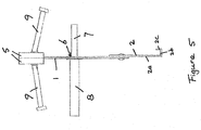
- an elongate extension 2 is movably secured to one face of divider plate 1.
- Divider plate 1 is an elongate flat section of material.
- the extension 2 is elongate and comprises an elongate side wall 2a, an elongate foot 2b and an elongate return edge 2c on the elongate foot 2b, resulting in an elongate extension 2 with a substantially J-shaped cross-section.
- Extension 2 has a substantially constant cross-section along its length.
- the elongate extension 2 is movable relative to the divider plate 1 between a fully retracted position and a fully extended position.
- the extension 2 can also be moved to a position anywhere between these two extremes.
- the extension 2 contains substantially vertical slots 3 at regular intervals.
- the slots 3 are adapted to receive rivets 4 which are also connected to the divider plate 1.
- the position of the extension 2 relative to the divider plate 1 can be adjusted in a continuous manner, and the extension 2 is attached to the divider plate 1 via a loose fit.
- the extension 2 has a stowed position, where the extension 2 and the divider plate 1 are held together by friction means (not shown), but if the extension 2 is moved down relative to the divider plate 1 by a predetermined distance (i.e. towards a more extended form), the extension 2 can drop down to the subbase under gravity while remaining attached to the divider plate 1.
- Divider plate 1 comprises apertures 6 along its length at regular intervals.
- the apertures 6 are adapted to receive dowel plates 7.
- the dowel plates 7 are encased in dowel sleeves 8, which, in use, allow movement of the concrete as it sets and shrinks.
- the apparatus further comprises edge rails 5 supported by divider plate 1.
- Anchor means 9 extend out from the edge rails 5 in the general direction where, in use, the concrete would be poured.
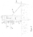
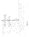
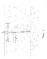
- FIGS 2 , 3 , 6 and 7 also show a jack 10, which does not form part of the apparatus of the invention, but which can be used to suspend the divider plate 1 at the desired finished floor level (FFL) before concrete is cast.
- the jack 10 can, for example, have a removable threaded end which fits through apertures in the edge rails 5.
- the threaded end can be secured to the edge rails 5 by securing it with a wing nut on the other side from the jack 10, while on the side of the jack 10, the threaded end fits inside the jack's square box section which runs up and down the threaded bar, allowing the height of the apparatus 1 relative to the subbase to be adjusted.
- Figures 3 , 6 and 7 also show pins 11a, 11b and wedges 12, which do not form part of the apparatus of the invention, but which can be used to secure the apparatus to the subbase in the desired location.
- the divider plate 1 is suspended at the desired FFL using support means, which can include suspension means such as, for example, a jack 10.
- suspension means such as, for example, a jack 10.
- the jack 10 is secured to the subbase via a pin 11b.
- the extension 2 can be in its stowed form.
- the extension 2 is then moved down relative to the divider plate 1 by a predetermined distance, past the friction means which was holding it in place (not shown); after this the extension 2 can drop down to the subbase under gravity, while remaining attached to the divider plate 1 via a loose fit.
- An additional pin 11a is then placed in the ground on the same side of the divider plate 1 as the extension 2 and the jack 10.
- Wedges 12 are placed between the pin 11a and the extension 2 and/or the divider plate 1, in order to secure the apparatus to the subbase in the desired location and prevent movement caused by the thrust of the concrete.
- the apparatus will form at least part of an edge of a space for casting concrete.
- the entire edge may be formed by the apparatus, and the remaining edges may also be formed by further units of the apparatus.
- the apparatus of the invention can alleviate the need to manufacture, transport and stock a large number of different sizes of divider plates to suit all customer needs. Instead, a desired formwork height can be achieved by using a single size of divider plate, while avoiding a gap between the subbase and the divider plate which concrete can flow through. Furthermore, the apparatus of the invention can be easier to operate than existing apparatus in this field, and can achieve a desired finished floor level (FFL) to a high level of precision. Therefore the apparatus can enhance the ease with which concrete floor slab panels can be produced, and can enhance the performance characteristics of the resulting concrete floor slabs.
- FTL finished floor level
Applications Claiming Priority (3)
| Application Number | Priority Date | Filing Date | Title |
|---|---|---|---|
| GB1218666.4A GB2507071B (en) | 2012-10-17 | 2012-10-17 | Apparatus for forming an edge of a concrete floor slab panel and method of manufacturing a concrete floor slab panel |
| PCT/GB2013/052704 WO2014060752A1 (fr) | 2012-10-17 | 2013-10-16 | Appareil |
| EP13794950.9A EP2912227B2 (fr) | 2012-10-17 | 2013-10-16 | Rail de bordure pour dalles en beton |
Related Parent Applications (2)
| Application Number | Title | Priority Date | Filing Date |
|---|---|---|---|
| EP13794950.9A Division EP2912227B2 (fr) | 2012-10-17 | 2013-10-16 | Rail de bordure pour dalles en beton |
| EP13794950.9A Division-Into EP2912227B2 (fr) | 2012-10-17 | 2013-10-16 | Rail de bordure pour dalles en beton |
Publications (1)
| Publication Number | Publication Date |
|---|---|
| EP3572584A1 true EP3572584A1 (fr) | 2019-11-27 |
Family
ID=47324937
Family Applications (2)
| Application Number | Title | Priority Date | Filing Date |
|---|---|---|---|
| EP13794950.9A Active EP2912227B2 (fr) | 2012-10-17 | 2013-10-16 | Rail de bordure pour dalles en beton |
| EP19181695.8A Pending EP3572584A1 (fr) | 2012-10-17 | 2013-10-16 | Appareil |
Family Applications Before (1)
| Application Number | Title | Priority Date | Filing Date |
|---|---|---|---|
| EP13794950.9A Active EP2912227B2 (fr) | 2012-10-17 | 2013-10-16 | Rail de bordure pour dalles en beton |
Country Status (10)
| Country | Link |
|---|---|
| EP (2) | EP2912227B2 (fr) |
| AU (1) | AU2013333646B2 (fr) |
| DK (1) | DK2912227T3 (fr) |
| ES (1) | ES2753229T5 (fr) |
| GB (1) | GB2507071B (fr) |
| HU (1) | HUE047594T2 (fr) |
| LT (1) | LT2912227T (fr) |
| PL (1) | PL2912227T3 (fr) |
| PT (1) | PT2912227T (fr) |
| WO (1) | WO2014060752A1 (fr) |
Families Citing this family (11)
| Publication number | Priority date | Publication date | Assignee | Title |
|---|---|---|---|---|
| US10077551B2 (en) * | 2015-10-05 | 2018-09-18 | Illinois Tool Works Inc. | Joint edge assembly and method for forming joint in offset position |
| US10119281B2 (en) | 2016-05-09 | 2018-11-06 | Illinois Tool Works Inc. | Joint edge assembly and formwork for forming a joint, and method for forming a joint |
| AU2018226389A1 (en) | 2017-10-13 | 2019-05-02 | Illinois Tool Works Inc. | Edge protection system having bridging pins |
| AU2018226390A1 (en) | 2017-10-13 | 2019-05-02 | Illinois Tool Works Inc. | Edge protection system having retaining clip |
| AU2018226391A1 (en) | 2017-10-13 | 2019-05-02 | Illinois Tool Works Inc. | Edge protection system having support foot |
| AU2018226394A1 (en) | 2017-10-13 | 2019-05-02 | Illinois Tool Works Inc. | Edge protection system having clip retainment |
| AU2018226393A1 (en) | 2017-10-13 | 2019-05-02 | Illinois Tool Works Inc. | Edge protection system with intersection module |
| AU2018226392A1 (en) | 2017-10-13 | 2019-05-02 | Illinois Tool Works Inc. | Edge protection system having dowel plate |
| AU2019264633A1 (en) | 2018-11-19 | 2020-06-04 | Illinois Tool Works Inc. | Support bracket |
| US11578491B2 (en) * | 2020-02-07 | 2023-02-14 | Shaw Craftsmen Concrete, Llc | Topping slab installation methodology |
| CN111206779A (zh) * | 2020-02-27 | 2020-05-29 | 中国水利水电第九工程局有限公司 | 分隔浇筑装置及方法 |
Citations (6)
| Publication number | Priority date | Publication date | Assignee | Title |
|---|---|---|---|---|
| FR2785632A1 (fr) | 1998-11-10 | 2000-05-12 | Ppc Sa | Joint de dilatation |
| DE20209468U1 (de) * | 2002-06-18 | 2002-08-29 | Kaemmerling Christoph | Schalungselement |
| EP1389648A1 (fr) | 2002-08-16 | 2004-02-18 | Permaban Products Limited | Dalle de béton |
| WO2008136690A1 (fr) * | 2007-05-04 | 2008-11-13 | Pcln Holdings Limited | Appareil de support d'ensemble de joint d'armature |
| DE202009000007U1 (de) * | 2009-01-07 | 2009-03-12 | Hammes, Herbert | Profilelement einer verlorenen Schalung und verlorene Schalung mit einem solchen Profilelement |
| FR2964131A1 (fr) | 2010-08-30 | 2012-03-02 | Sifloor | Dispositif de reglage de la hauteur d'un coffrage pour dalles de beton |
Family Cites Families (9)
| Publication number | Priority date | Publication date | Assignee | Title |
|---|---|---|---|---|
| DE3346318A1 (de) * | 1983-12-22 | 1985-07-04 | Reinhold 6296 Mengerskirchen Beck | Vorrichtung zur befestigung von schalplatten an einem bauwerk |
| DE29707239U1 (de) * | 1997-04-22 | 1997-07-10 | Fliesen & Fusbodentechnik E Un | Trennelement zur Abgrenzung zweier nebeneinander liegender Estrichlagen voneinander |
| DE20115167U1 (de) | 2001-09-13 | 2001-12-06 | Hammes Herbert | Tagesfeldabstellung |
| DE20209995U1 (de) | 2002-06-28 | 2002-11-21 | Zueblin Ag | Betonierfugenausbildung in der Bodenplatte |
| EP1905898B1 (fr) | 2006-09-22 | 2010-06-16 | Plakabeton S.A. | Dispositif pour équiper un joint de dilatation entre des dalles de béton |
| GB0811427D0 (en) * | 2008-06-20 | 2008-07-30 | Permaban Ltd | Screed rail apparatus |
| GB2475289A (en) * | 2009-11-12 | 2011-05-18 | Peikko Group Oy | Apparatus for adjusting the height of a floor joint system |
| US20120124929A1 (en) * | 2010-11-22 | 2012-05-24 | O'connor Paul Allison | Concrete armored joint form that provides one step installation and thermal transfer prevention as well as seating for joint filler |
| AR090164A1 (es) | 2012-02-27 | 2014-10-22 | Hengelhoef Concrete Joints Mfg Nv | Junta de expansion |
-
2012
- 2012-10-17 GB GB1218666.4A patent/GB2507071B/en active Active
-
2013
- 2013-10-16 WO PCT/GB2013/052704 patent/WO2014060752A1/fr active Application Filing
- 2013-10-16 HU HUE13794950A patent/HUE047594T2/hu unknown
- 2013-10-16 AU AU2013333646A patent/AU2013333646B2/en active Active
- 2013-10-16 PT PT137949509T patent/PT2912227T/pt unknown
- 2013-10-16 EP EP13794950.9A patent/EP2912227B2/fr active Active
- 2013-10-16 ES ES13794950T patent/ES2753229T5/es active Active
- 2013-10-16 EP EP19181695.8A patent/EP3572584A1/fr active Pending
- 2013-10-16 DK DK13794950T patent/DK2912227T3/da active
- 2013-10-16 LT LT13794950T patent/LT2912227T/lt unknown
- 2013-10-16 PL PL13794950T patent/PL2912227T3/pl unknown
Patent Citations (6)
| Publication number | Priority date | Publication date | Assignee | Title |
|---|---|---|---|---|
| FR2785632A1 (fr) | 1998-11-10 | 2000-05-12 | Ppc Sa | Joint de dilatation |
| DE20209468U1 (de) * | 2002-06-18 | 2002-08-29 | Kaemmerling Christoph | Schalungselement |
| EP1389648A1 (fr) | 2002-08-16 | 2004-02-18 | Permaban Products Limited | Dalle de béton |
| WO2008136690A1 (fr) * | 2007-05-04 | 2008-11-13 | Pcln Holdings Limited | Appareil de support d'ensemble de joint d'armature |
| DE202009000007U1 (de) * | 2009-01-07 | 2009-03-12 | Hammes, Herbert | Profilelement einer verlorenen Schalung und verlorene Schalung mit einem solchen Profilelement |
| FR2964131A1 (fr) | 2010-08-30 | 2012-03-02 | Sifloor | Dispositif de reglage de la hauteur d'un coffrage pour dalles de beton |
Also Published As
| Publication number | Publication date |
|---|---|
| PT2912227T (pt) | 2019-11-06 |
| PL2912227T3 (pl) | 2020-03-31 |
| ES2753229T3 (es) | 2020-04-07 |
| HUE047594T2 (hu) | 2020-05-28 |
| GB201218666D0 (en) | 2012-11-28 |
| EP2912227A1 (fr) | 2015-09-02 |
| GB2507071B (en) | 2017-08-02 |
| DK2912227T3 (da) | 2019-11-11 |
| GB2507071A (en) | 2014-04-23 |
| ES2753229T5 (es) | 2023-04-04 |
| LT2912227T (lt) | 2019-12-10 |
| EP2912227B1 (fr) | 2019-07-31 |
| WO2014060752A1 (fr) | 2014-04-24 |
| AU2013333646A1 (en) | 2015-06-04 |
| EP2912227B2 (fr) | 2022-12-07 |
| AU2013333646B2 (en) | 2017-03-30 |
Similar Documents
| Publication | Publication Date | Title |
|---|---|---|
| AU2013333646B2 (en) | Apparatus | |
| EP2946037B1 (fr) | Structure de joint | |
| WO2013076500A1 (fr) | Appareil servant à former un bord d'un plancher en béton | |
| EP1389648B1 (fr) | Dalle de béton | |
| AU2015216827B2 (en) | A prefabricated movement joint system for concrete floors | |
| EP3749816A1 (fr) | Système de coffrage | |
| WO2009153604A1 (fr) | Appareil à rails pour règle à araser | |
| GB2500626A (en) | Zig zag concrete floor joint apparatus | |
| WO2010034987A2 (fr) | Appareil pour définir les bords de dalles adjacentes de plancher en béton | |
| AU2010214742B2 (en) | Expansion joints | |
| KR200483776Y1 (ko) | 합벽지지대 | |
| CA2493492A1 (fr) | Systemes de table de coffrage de dalles | |
| WO2015121538A1 (fr) | Système de joint de dilatation préfabriqué pour sols en béton | |
| CN213538591U (zh) | 一种混凝土假缝传力杆托架 | |
| BR112015008649B1 (pt) | Aparelho para a formação de uma borda de um painel de placa de piso de concreto, painel de placa de piso de concreto, piso de concreto e método de fabricação dos mesmos | |
| WO2010008309A1 (fr) | Système de coffrage pour plancher | |
| KR102561363B1 (ko) | 건축물 보 성형을 위한 거푸집의 보지 장치 | |
| DE10314926A1 (de) | Verfahren und Richthilfe zum Einrichten der Lage einer Betonfertigteilplatte sowie Betonfertigteilplatte | |
| KR20090105907A (ko) | 자동상승장치용 리프팅유닛 장착장치 | |
| NZ621895B (en) | A prefabricated movement joint system for concrete floors |
Legal Events
| Date | Code | Title | Description |
|---|---|---|---|
| PUAI | Public reference made under article 153(3) epc to a published international application that has entered the european phase |
Free format text: ORIGINAL CODE: 0009012 |
|
| STAA | Information on the status of an ep patent application or granted ep patent |
Free format text: STATUS: THE APPLICATION HAS BEEN PUBLISHED |
|
| AC | Divisional application: reference to earlier application |
Ref document number: 2912227 Country of ref document: EP Kind code of ref document: P |
|
| AK | Designated contracting states |
Kind code of ref document: A1 Designated state(s): AL AT BE BG CH CY CZ DE DK EE ES FI FR GB GR HR HU IE IS IT LI LT LU LV MC MK MT NL NO PL PT RO RS SE SI SK SM TR |
|
| STAA | Information on the status of an ep patent application or granted ep patent |
Free format text: STATUS: REQUEST FOR EXAMINATION WAS MADE |
|
| 17P | Request for examination filed |
Effective date: 20200522 |
|
| RBV | Designated contracting states (corrected) |
Designated state(s): AL AT BE BG CH CY CZ DE DK EE ES FI FR GB GR HR HU IE IS IT LI LT LU LV MC MK MT NL NO PL PT RO RS SE SI SK SM TR |
|
| RIC1 | Information provided on ipc code assigned before grant |
Ipc: E04B 5/32 20060101ALN20220328BHEP Ipc: E04B 1/48 20060101ALN20220328BHEP Ipc: E04F 15/14 20060101ALI20220328BHEP Ipc: E01C 11/14 20060101AFI20220328BHEP |
|
| GRAP | Despatch of communication of intention to grant a patent |
Free format text: ORIGINAL CODE: EPIDOSNIGR1 |
|
| STAA | Information on the status of an ep patent application or granted ep patent |
Free format text: STATUS: GRANT OF PATENT IS INTENDED |
|
| RIC1 | Information provided on ipc code assigned before grant |
Ipc: E04B 5/32 20060101ALN20220503BHEP Ipc: E04B 1/48 20060101ALN20220503BHEP Ipc: E04F 15/14 20060101ALI20220503BHEP Ipc: E01C 11/14 20060101AFI20220503BHEP |
|
| TPAC | Observations filed by third parties |
Free format text: ORIGINAL CODE: EPIDOSNTIPA |
|
| INTG | Intention to grant announced |
Effective date: 20220518 |
|
| GRAJ | Information related to disapproval of communication of intention to grant by the applicant or resumption of examination proceedings by the epo deleted |
Free format text: ORIGINAL CODE: EPIDOSDIGR1 |
|
| STAA | Information on the status of an ep patent application or granted ep patent |
Free format text: STATUS: REQUEST FOR EXAMINATION WAS MADE |
|
| STAA | Information on the status of an ep patent application or granted ep patent |
Free format text: STATUS: EXAMINATION IS IN PROGRESS |
|
| INTC | Intention to grant announced (deleted) | ||
| 17Q | First examination report despatched |
Effective date: 20221010 |
|
| P01 | Opt-out of the competence of the unified patent court (upc) registered |
Effective date: 20230518 |
|
| RAP1 | Party data changed (applicant data changed or rights of an application transferred) |
Owner name: LEVIAT LIMITED |
|
| RIN1 | Information on inventor provided before grant (corrected) |
Inventor name: SPURRELL, SHAUN ANTHONY |