EP3572275A1 - Siège de véhicule - Google Patents
Siège de véhicule Download PDFInfo
- Publication number
- EP3572275A1 EP3572275A1 EP19174170.1A EP19174170A EP3572275A1 EP 3572275 A1 EP3572275 A1 EP 3572275A1 EP 19174170 A EP19174170 A EP 19174170A EP 3572275 A1 EP3572275 A1 EP 3572275A1
- Authority
- EP
- European Patent Office
- Prior art keywords
- vehicle seat
- pivot axis
- damper
- spring
- damping
- Prior art date
- Legal status (The legal status is an assumption and is not a legal conclusion. Google has not performed a legal analysis and makes no representation as to the accuracy of the status listed.)
- Granted
Links
- 238000013016 damping Methods 0.000 claims abstract description 76
- 239000000725 suspension Substances 0.000 claims description 34
- 238000006073 displacement reaction Methods 0.000 description 4
- 230000000694 effects Effects 0.000 description 4
- 239000000463 material Substances 0.000 description 3
- 230000000295 complement effect Effects 0.000 description 2
- 230000001419 dependent effect Effects 0.000 description 2
- 230000005484 gravity Effects 0.000 description 2
- 230000005489 elastic deformation Effects 0.000 description 1
Images


Classifications
-
- B—PERFORMING OPERATIONS; TRANSPORTING
- B60—VEHICLES IN GENERAL
- B60N—SEATS SPECIALLY ADAPTED FOR VEHICLES; VEHICLE PASSENGER ACCOMMODATION NOT OTHERWISE PROVIDED FOR
- B60N2/00—Seats specially adapted for vehicles; Arrangement or mounting of seats in vehicles
- B60N2/24—Seats specially adapted for vehicles; Arrangement or mounting of seats in vehicles for particular purposes or particular vehicles
- B60N2/38—Seats specially adapted for vehicles; Arrangement or mounting of seats in vehicles for particular purposes or particular vehicles specially constructed for use on tractors or like off-road vehicles
- B60N2/39—Seats tiltable to compensate for roll inclination of vehicles
-
- B—PERFORMING OPERATIONS; TRANSPORTING
- B60—VEHICLES IN GENERAL
- B60N—SEATS SPECIALLY ADAPTED FOR VEHICLES; VEHICLE PASSENGER ACCOMMODATION NOT OTHERWISE PROVIDED FOR
- B60N2/00—Seats specially adapted for vehicles; Arrangement or mounting of seats in vehicles
- B60N2/50—Seat suspension devices
- B60N2/502—Seat suspension devices attached to the base of the seat
-
- B—PERFORMING OPERATIONS; TRANSPORTING
- B60—VEHICLES IN GENERAL
- B60N—SEATS SPECIALLY ADAPTED FOR VEHICLES; VEHICLE PASSENGER ACCOMMODATION NOT OTHERWISE PROVIDED FOR
- B60N2/00—Seats specially adapted for vehicles; Arrangement or mounting of seats in vehicles
- B60N2/50—Seat suspension devices
- B60N2/52—Seat suspension devices using fluid means
- B60N2/522—Seat suspension devices using fluid means characterised by dampening means
-
- B—PERFORMING OPERATIONS; TRANSPORTING
- B60—VEHICLES IN GENERAL
- B60N—SEATS SPECIALLY ADAPTED FOR VEHICLES; VEHICLE PASSENGER ACCOMMODATION NOT OTHERWISE PROVIDED FOR
- B60N2/00—Seats specially adapted for vehicles; Arrangement or mounting of seats in vehicles
- B60N2/50—Seat suspension devices
- B60N2/54—Seat suspension devices using mechanical springs
- B60N2/542—Seat suspension devices using mechanical springs made of rubber or other material having high internal friction, e.g. polymers
-
- B—PERFORMING OPERATIONS; TRANSPORTING
- B60—VEHICLES IN GENERAL
- B60N—SEATS SPECIALLY ADAPTED FOR VEHICLES; VEHICLE PASSENGER ACCOMMODATION NOT OTHERWISE PROVIDED FOR
- B60N2/00—Seats specially adapted for vehicles; Arrangement or mounting of seats in vehicles
- B60N2/50—Seat suspension devices
- B60N2/54—Seat suspension devices using mechanical springs
- B60N2/546—Leaf- or flexion springs
-
- B—PERFORMING OPERATIONS; TRANSPORTING
- B60—VEHICLES IN GENERAL
- B60N—SEATS SPECIALLY ADAPTED FOR VEHICLES; VEHICLE PASSENGER ACCOMMODATION NOT OTHERWISE PROVIDED FOR
- B60N2/00—Seats specially adapted for vehicles; Arrangement or mounting of seats in vehicles
- B60N2/02—Seats specially adapted for vehicles; Arrangement or mounting of seats in vehicles the seat or part thereof being movable, e.g. adjustable
- B60N2002/0204—Seats specially adapted for vehicles; Arrangement or mounting of seats in vehicles the seat or part thereof being movable, e.g. adjustable characterised by the seat or seat part turning about or moving along a non-standard, particular axis, i.e. an axis different from the axis characterising the conventional movement
- B60N2002/0212—Seats specially adapted for vehicles; Arrangement or mounting of seats in vehicles the seat or part thereof being movable, e.g. adjustable characterised by the seat or seat part turning about or moving along a non-standard, particular axis, i.e. an axis different from the axis characterising the conventional movement the seat or seat part turning about or moving along a longitudinal axis
-
- B—PERFORMING OPERATIONS; TRANSPORTING
- B60—VEHICLES IN GENERAL
- B60N—SEATS SPECIALLY ADAPTED FOR VEHICLES; VEHICLE PASSENGER ACCOMMODATION NOT OTHERWISE PROVIDED FOR
- B60N2/00—Seats specially adapted for vehicles; Arrangement or mounting of seats in vehicles
- B60N2/02—Seats specially adapted for vehicles; Arrangement or mounting of seats in vehicles the seat or part thereof being movable, e.g. adjustable
- B60N2002/0204—Seats specially adapted for vehicles; Arrangement or mounting of seats in vehicles the seat or part thereof being movable, e.g. adjustable characterised by the seat or seat part turning about or moving along a non-standard, particular axis, i.e. an axis different from the axis characterising the conventional movement
- B60N2002/0216—Seats specially adapted for vehicles; Arrangement or mounting of seats in vehicles the seat or part thereof being movable, e.g. adjustable characterised by the seat or seat part turning about or moving along a non-standard, particular axis, i.e. an axis different from the axis characterising the conventional movement the seat or seat part turning about or moving along a transversal axis
Definitions
- the connecting part is designed and provided such that the first spring bar and the pivot axis are connected to one another.
- the connecting part is in operative connection with the upper part, that is, in a pivoting movement of the upper part relative to the lower part, the connecting part is also pivoted about the pivot axis.
- the pivot axis is arranged extending in the vehicle longitudinal direction.
- the second damping device is arranged in a vehicle seat height direction below the first damping device and below the spring device.
- the second damping device has a third damper, which is arranged parallel to the second damper and the second damper and the third damper are arranged in a first common plane which is parallel to the plane formed from the vehicle longitudinal direction and the vehicle seat width direction.
- Such a configuration makes it possible to change the acting force of the second damping device.
- the pivot axis is preferably formed as a bearing axis and the pivot axis has a first end and a second end, wherein the first end and the second end of the pivot axis are connected to the lower suspension part.
- pivot axis is designed as a bearing shaft, that is, in particular rotatably mounted.
- a first bearing block and a second bearing block are provided, which are each rigidly connected to the lower part and the first bearing block, the first end of the pivot axis and the second bearing block supports the second end of the pivot axis.
- the first spring bar has a first end and a second end, wherein the first end of the first spring bar and the second end of the spring bar are connected to the suspension base, in particular rigidly connected. This allows a much higher rigidity can be achieved. By a rigid connection can also be ruled out that occur in a deformation of the first spring rod unwanted rotational movements of the first spring bar and lead to undesirable effects on the spring properties.
- first end of the first spring bar is connected to the first bearing block and the second end of the first spring bar to the second bearing block.
- the connecting part is connected to the pivot axis such that upon rotation of the pivot axis, the connecting part along the pivot axis is displaceable.
- the pivot axis or the bearing shaft is designed as a rotary spindle and the connecting part correspondingly complementary complementary is trained.
- the connecting part is displaced along the rotary spindle, in particular displaced translationally.
- the connecting part can be displaced by applying a tension or pressure in the direction of the pivot axis, for example by using corresponding pneumatic cylinders, Bowden cables, or the like.
- the connecting part may also be referred to as a trolley.
- the seat suspension on a second deformable in the radial direction spring bar, which has a first end and a second end, wherein the first end of the second spring bar and the second end of the second spring bar are connected to the suspension base and the connecting part of the second spring bar and the pivot axis connects.
- the statements concerning the first spring bar can also apply to the second spring bar.
- the second spring bar lies in the common plane.
- first spring bar and a second spring bar can be provided, the suspension properties of the spring device can be changed even better. Likewise, the spring rate or stiffness of the spring device changes.
- At least one spring bar is arranged at an angle to the pivot axis.
- first spring bar and the second spring bar are each arranged at an angle to the pivot axis, in particular, the first and the second spring bar may be arranged symmetrically to the pivot axis.
- the connecting part has a first passage and possibly a second passage through which the first spring bar and optionally the second spring bar run.
- the spring device When driving over very uneven terrain, the spring device is exposed to strong alternating loads. It may well be that the passages of the connecting part deflect over time and it comes to an undesirable play in the suspension. Characterized in that the ends of the spring bars are arranged at different distances from each other, so the spring bars wedge-shaped to each other, however, the passage distance in the connecting part is constant, the suspension rods extend to the connecting part substantially parallel and not parallel to the connecting part. In this way, the spring rods exert a lateral force on the passages of the connecting part, so that resulting play can be compensated by the existing bias and is not noticeable over a long period of time.
- the connecting part has a rocker-like structure, wherein a first rocker element is arranged at a first end of the rocker-like structure and a second rocker element at the second end of the rocker-like structure, wherein at least the first rocker element and the second rocker element with the upper part in operative contact.
- first rocker element and the second rocker element each have a first region, which is trapezoidal in cross-section, and a second region, which is rectangular in cross-section, on.
- first region is arranged below the second region when viewed in the vertical direction.
- an end stop of the connecting part is defined, characterized in that when the connecting part is pivoted so far around the pivot axis, that a side which has the rocking point as a corner, is in communication with the lower part.
- the mutually parallel sides of the trapezoid preferably extend in the vertical direction.
- the first spring bar, the connection unit and the pivot axis are arranged in the vehicle seat height direction between the upper part and the lower part. As a result, a further reduction in space can be made.
- the stroke of the first damper can be increased in a pivoting of the upper part relative to the lower part in contrast to a direct attachment of the first damper to the upper part and lower part.
- the fourth damper, and optionally the fifth damper and the sixth damper as well as the first damper are connected by means of lever elements to the upper part or the lower part.
- the first lever element has a first recess.
- Recess means in this case that an open area of the lever element is present, so that upon pivoting of the upper part, which is accompanied by a pivoting of the first lever member and the second lever member, relative to the lower part of a stop with a connection or suspension of the second lever member to the upper part can be prevented, in particular at a maximum deflection of the pivoting of the upper part relative to the lower part.
- a length of the upper part in the vehicle longitudinal direction is shorter than a length of the lower part in the vehicle longitudinal direction and wherein the respective damper with the first end on an inner side of a lower portion which is perpendicular to the lower part and connected thereto, and the second lever member on an outer side of a top portion which is perpendicular to the upper part, is connected.
- the lower part and the upper part are formed flat.
- the upper portion and the lower portion are also flat, connected to the upper part or the lower part and are perpendicular to it.
- the first damper and the fourth damper are arranged axially symmetrically to the pivot axis.
- the fifth damper and the sixth damper are arranged axially symmetrically to the pivot axis.
- the symmetry here also refers in particular to the normal operating state, that is, an undeflected operating state.
- FIG. 1A schematically the situation when one-way driving over an obstacle is shown, that is, a vehicle 33 (not shown here) is deflected unilaterally, with respect to a vehicle seat 1, which is shown schematically.
- the vehicle seat 1 shown here has no damping or suspension and no pivoting possibilities.
- On the right side of the Figure 1A the vehicle seat 1 is shown in a normal operating state 34.
- a one-sided deflection of the vehicle 33 results in various movements, namely a vertical deflection in vehicle seat height direction H upward, a horizontal deflection in vehicle seat width direction B and a rotation of the vehicle seat 1. Shown here is the movement of the center of gravity 56 of the vehicle seat 1. Left in the Figure 1A the vehicle seat 1 can be seen in a deflected operating state. Normal operating state here means that the vehicle seat 1 is not yet deflected; Accordingly, deflected operating state means that the vehicle seat 1 is deflected.
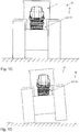
- FIG. 1B an inventive vehicle seat 1 is shown schematically, with certain components are characterized here.
- an upper part 3 of the vehicle seat 1 carries a booster seat 58, on which a seat part 60 and a backrest 59 are arranged. Armrests 61 may be arranged on the backrest 59.
- the upper part 3 is further pivotable relative to a lower part 4 by means of a pivot axis 5 about the pivot axis 5.
- the lower part 4, however, is arranged translationally displaceable relative to a body 57, indicated by the arrows to the left and to the right.
- FIG. 1D is the vehicle seat 1 of Figure 1C to recognize, in which case the vehicle 33 and the vehicle seat 1 are in a deflected operating condition 35.
- the vehicle 33 is deflected only on one side, in the present case considered the right side.
- the vehicle seat 1 accordingly has a vertical deflection 53, a horizontal deflection 54 and a rotation 55, wherein the respective movement is counteracted according to the invention by a suspension device 2, a first damping device 27 and a second damping device 62.
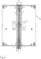
- FIG. 2A shows the suspension device 2 according to the invention of the vehicle seat 1 according to a preferred embodiment in a plan view.
- a connecting part 8 which has a first passage 36 and a second passage 37, wherein a first spring bar 6 extends through the first passage 36 and a second spring bar 14 extends through the second passage 37.
- the passages 36, 37 extend here in a vehicle seat longitudinal direction L.
- a third passage 40 can be seen, through which the pivot axis 5 extends, wherein the pivot axis 5 is in operative connection with the connecting part 8.
- the connecting part 8 with a rocker-like structure 21 comprising a first rocker element 19 and a second rocker element 20, which are interconnected by a central element 41.
- the middle element 41 has passages 36, 37, 40.
- the suspension device 2 has a rotary knob 39, which is connected to the pivot axis 5.
- the knob 39 By operating the knob 39, that is, by rotation of the knob, the pivot axis 5 is also rotated about its own axis.
- the connecting member 8 By rotation of the pivot axis 5 while the connecting member 8 is displaced in the vehicle longitudinal direction L to the rear or to the front, whereby the spring characteristics of the spring means 2 are adjustable.
- a first stop element 38 and a second stop element 42 are provided, which limit the displacement of the connecting part 8 in the vehicle longitudinal direction L.
- the first stop element 38 is arranged such that the connecting element 8 is positioned on reaching the first stop element 38 in a central position, that is, the connecting part 8 is symmetrical with respect to the center of the upper part 3, wherein the center in the vehicle longitudinal direction L is meant ,
- damping device 27 of FIG. 2A can be seen, with a first damper 30, wherein here also a fourth damper 65, a fifth damper 66 and a sixth damper 67 of the first damping device 21 are provided.
- FIG. 2B shows the section AA, which in the FIG. 2A is drawn.
- the Figure 2C shows a section B of FIG. 2B in an enlargement.
- FIG. 2D shows a front view of FIG. 2A ,
- FIG. 3 shows a cross section through the connecting part 8, and wherein the connecting part 8 has a rocker-like structure 21, with a first end 22 and a second end 23. At the first end 22 of the structure 21, a first rocker element 19 and at the second end 23 arranged a second rocker element 20 of the structure.
- Each rocker element 19, 20 has a trapezoidal region 24 and a rectangular region 25, wherein this configuration (trapezoid, rectangle) refers to the illustrated cross section.
- the rectangular region 25 is seen in vehicle seat height direction H seen above the trapezoidal region 24 and is in operative contact with the upper part 3.
- the middle element 41 has the first passage 36, the second passage 37 and the third passage 40, the first spring bar 6 extending through the first passage 36, the second spring bar 14 passing through the second passage and the pivot axis 5 passing through the third passage 40 extends.
- the middle element also comprises a rocking point 43, by means of which the connecting part 8 is operatively connected to the lower part 4.
- FIG. 3A shows the spring device 2 in a deflected operating state 35, that is, that the upper part 3 performs a pivoting movement relative to the lower part 4. Since in this case the connecting part 8 is in operative contact on the one hand with the upper part 3, the connecting part 8 is also pivoted about the pivot axis 5. This has the consequence that also the passages 36, 37 are pivoted about the pivot axis 5 and consequently also the first spring bar 6 and the second spring bar 14; Sometimes the spring rods 6, 14 are elastically deformed. Likewise, the connecting part 8 by means of the rocker point 43 with the lower part 4 in operative contact, so that the connecting part 8 is pivoted about this rocker point 43.
- the upper part 3 and the lower part 4 are arranged substantially parallel to each other, so include the upper part 3 and the lower part 4 in the deflected operating condition 35 now an angle 49 and the first spring bar 6 and the second spring bar 14 are now one Value of a deflection 48 in vehicle seat height direction H shifted from each other.
- a side 50 of the trapezoidal region 24 of the first rocker element 19 can be seen, which comprises the rocking point 43 and which can act as a limitation of the pivoting movement of the upper part 3. If the side 50 is in contact with the lower part 4, further pivoting of the upper part 3 relative to the lower part 4 in this direction is no longer possible. The same naturally applies to the further trapezoidal region 24 of the second rocker element 20.
- FIG. 3C shows as well as the FIG. 2D a front view of the spring device 2, but in the deflected operating condition 35th Der FIG. 3C is particularly good to recognize the movement of the first lever member 28 and the second lever member 29.
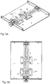
- FIG. 6A shows a particularly preferred embodiment of a first damping device 21, which in the present case comprises a first damper 30, a fourth damper 65, a fifth damper 66 and a sixth damper 67.
- Each of these dampers 30, 65, 66, 67 has a first end 31 and a second end 32, wherein the first end 31 of the damper 30, 65, 66, 67 by means of a first pivot axis 44 is pivotally connected to the lower part 4, and wherein the second end 32 of the damper 30, 65, 66, 67 is pivotally connected to a first lever element 28 by means of a fifth pivot axis 68.
- first lever element 28 is pivotally connected to the lower part 4 by means of a second pivot axis 45
- a second lever element 29 being pivotably connected to the first lever element 28 by means of a third pivot axis 46 and being pivotally connected to the upper part by means of a fourth pivot axis 47 3 is connected.
- FIG. 6B is the subject of FIG. 6A to recognize, however, in a deflected position 35, that is, that the upper part 3 is pivoted relative to the lower part 4 about the pivot axis 5. Accordingly, it can be seen that the stroke of the dampers 30, 65, 66, 67 is changed accordingly, that is, that the length of the extended piston 69 for each damper 30, 65, 66, 67 is changed.
- first damper 30 and the fourth damper 65 are arranged symmetrically to the pivot axis 5. The same applies equally to the fifth damper 66 and the sixth damper 67.
- first lever element 28 is connected to the second end 31 of the first damper 30 and comprises a first lever element part 70 and a second lever element part 71, wherein the second end 31 of the damper 30, 65, 66, 67 between the first Lever member part 70 and the second lever member part 71, seen in the vehicle longitudinal direction L, is arranged.
- dampers 30, 65, 66, 67 are arranged extending in the vehicle seat width direction B, respectively.
- the upper part 3 has a length 72, seen in the vehicle longitudinal direction L, on, which compared to a length 73 of the lower part 4, as seen in the vehicle longitudinal direction L, is smaller.
- the upper part 3 has a top part 74 and the bottom part 4 has a bottom part section 75, which are each designed to extend perpendicular thereto.
- the dampers 30, 65, 66, 67 viewed in the vehicle longitudinal direction L, between an outer side 76 of the upper portion 74 and an inner side 77 of the lower portion 75.
- a second damper 63 and a third damper 64 of the second damping device 62 can be seen, wherein the second damper 63 is arranged parallel to the third damper 64.
- the dampers 63, 64 are arranged in a plane parallel to the plane formed by the vehicle seat longitudinal direction L and the vehicle seat width direction B.
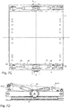
- FIG. 7B shows the subject of the FIG. 7A in a front view, also in the normal operating state 34.
- a third distance 78 between the fifth pivot axis 68 and the second pivot axis 45 is greater than a fourth distance 79 between the third pivot axis 46 and the fourth pivot axis 47.
- the third distance 78 is twice as large as the fourth distance 79th ,
- the first lever member 28 and the lever member parts 70, 71 are formed flat, and the first lever member 28 and the lever member parts 70, 71 are preferably in a plane or parallel planes, which is / are formed from the vehicle seat width direction B and vehicle seat height direction H with an extent in vehicle longitudinal direction L.
- first pivot axis 44 seen in the vehicle seat height direction H, is arranged above the pivot axis 5.
- FIG. 8B is the underlying operating principle in contrast to the principle of operation of the prior art, as shown in Figure 48, shown.
- the Figure 8A shows a fixed suspension of the damper 30, 65, 66, 67 on the lower part 4 and a stationary suspension on the upper part 3.
- Stationary means stationary except for rotation.
- the damper 30, 65, 66, 67 is also pivoted about the first pivot axis 44.
- a fifth distance 84 of the fourth pivot axis 47 to the pivot axis 5 and a sixth distance 85 of the pivot axis 5 to the first pivot axis 44 is constant
- a variable is the length 86 of the first pivot axis 44 to the fourth pivot axis 47, along with a change of Hubes of the damper 30, 65, 66, 67.
- the fifth distance 84 is still constant and the sixth distance 85.
- the length 86 of the first pivot axis 44 to the fourth pivot axis 47 via the first lever member 28 and the second lever member 29 is fundamentally different.
- the length 86 is now composed of the first distance 17, the seventh distance 87 from the third pivot axis 46 to the fifth pivot axis 68 and the eighth distance 88 of the fifth pivot axis 68 to the first pivot axis 44.
- the eighth distance 88 are significantly changed over the prior art, along with a significantly larger stroke change of the damper 30, 65, 66, 67 at the same deflection of the upper part. 3
- FIG. 9A, 9B and 9C are respectively front views, the Figure 9A the operation of the second damping device 62, the FIG. 9B the operation of the suspension device 2 and the first damping device 21 and the FIG. 9C the operation of the combination of the spring device 2, the first damping device 21 and the second damping device 62 shows.
Landscapes
- Engineering & Computer Science (AREA)
- Aviation & Aerospace Engineering (AREA)
- Transportation (AREA)
- Mechanical Engineering (AREA)
- Seats For Vehicles (AREA)
- Vehicle Body Suspensions (AREA)
Applications Claiming Priority (1)
| Application Number | Priority Date | Filing Date | Title |
|---|---|---|---|
| DE102018112036.2A DE102018112036B4 (de) | 2018-05-18 | 2018-05-18 | Fahrzeugsitz |
Publications (2)
| Publication Number | Publication Date |
|---|---|
| EP3572275A1 true EP3572275A1 (fr) | 2019-11-27 |
| EP3572275B1 EP3572275B1 (fr) | 2020-08-26 |
Family
ID=66529910
Family Applications (1)
| Application Number | Title | Priority Date | Filing Date |
|---|---|---|---|
| EP19174170.1A Active EP3572275B1 (fr) | 2018-05-18 | 2019-05-13 | Siège de véhicule |
Country Status (3)
| Country | Link |
|---|---|
| EP (1) | EP3572275B1 (fr) |
| CN (1) | CN110497829B (fr) |
| DE (1) | DE102018112036B4 (fr) |
Families Citing this family (6)
| Publication number | Priority date | Publication date | Assignee | Title |
|---|---|---|---|---|
| DE102019134238B4 (de) * | 2019-12-13 | 2023-09-14 | Grammer Aktiengesellschaft | Fahrzeugsitz mit Scherengestellanordnung |
| DE102019134244B4 (de) | 2019-12-13 | 2024-08-01 | Grammer Aktiengesellschaft | Fahrzeugsitz mit Scherengestellanordnung |
| DE102019134237B4 (de) * | 2019-12-13 | 2024-05-29 | Grammer Aktiengesellschaft | Fahrzeugsitz mit einer Federeinheit zum Federn von Wank- und Vertikalfederbewegungen |
| DE102019134234B4 (de) * | 2019-12-13 | 2024-05-29 | Grammer Aktiengesellschaft | Fahrzeugsitz mit einer Federeinheit zum Federn von Wank- und Vertikalfederbewegungen |
| DE102020103782B4 (de) * | 2020-02-13 | 2024-03-28 | Grammer Aktiengesellschaft | Fahrzeugsitz mit einer Vorrichtung zur Niveauregulierung- und stabilisierung |
| WO2023009518A1 (fr) | 2021-07-29 | 2023-02-02 | Toyota Motor Engineering & Manufacturing North America, Inc. | Ensembles sièges pourvus de cadres fixes et coussins de siège mobiles |
Citations (4)
| Publication number | Priority date | Publication date | Assignee | Title |
|---|---|---|---|---|
| US2489981A (en) * | 1946-03-20 | 1949-11-29 | Harold C Rose | Seat suspension for all implements |
| US5409295A (en) * | 1993-05-25 | 1995-04-25 | Omniflex Specialties | Omnidirectional tilting mechanism |
| EP2423039A1 (fr) * | 2010-08-30 | 2012-02-29 | Grammer Ag | Dispositif d'amortissement de vibrations pour véhicule |
| WO2014176130A1 (fr) | 2013-04-23 | 2014-10-30 | Bose Corporation | Système de siège pour un véhicule |
Family Cites Families (18)
| Publication number | Priority date | Publication date | Assignee | Title |
|---|---|---|---|---|
| DE499488C (de) * | 1929-02-20 | 1930-06-06 | Max Naumann | Federnder Sitz fuer Fahrzeuge, insbesondere fuer Kraftfahrzeuge |
| US3098676A (en) * | 1961-04-20 | 1963-07-23 | Bostrom Corp | Seat suspension system |
| FR1385112A (fr) | 1964-03-06 | 1965-01-08 | Fauteuil de conduite pour engin mal ou pas du tout suspendu | |
| FR1543275A (fr) * | 1967-07-31 | 1968-10-25 | Peugeot | Nouvel agencement, à absorption d'énergie, d'un siège sur un véhicule |
| US3632076A (en) * | 1970-02-09 | 1972-01-04 | Thomas J Rogers Jr | Self-leveling seat structure |
| DE2154364A1 (de) | 1971-11-02 | 1973-05-10 | Faun Werke | Elastische abstuetzung des fahrerhauses von lastkraftwagen |
| IT939182B (it) * | 1971-11-11 | 1973-02-10 | Rejna A Spa | Sedile con effetto di molleggiamen to regolabile in particolare per veicoli industriali del tipo com prendente un giunto costituito da due parti concentricamente mobili collegate a mezzo di corpi elastici |
| JPS5785331U (fr) | 1980-11-15 | 1982-05-26 | ||
| CN2309244Y (zh) * | 1998-01-24 | 1999-03-03 | 巢凯年 | 车辆坐椅减振架 |
| ATE296216T1 (de) * | 2002-03-22 | 2005-06-15 | Milsco Mfg A Unit Of Jason Inc | Sitzaufhängung |
| US6793284B1 (en) * | 2003-03-19 | 2004-09-21 | L & P Property Management Company | Steel spring with dwell for chairs |
| JP2004291940A (ja) * | 2003-03-28 | 2004-10-21 | T S Tec Kk | 車両用シート |
| CN101495012A (zh) * | 2006-03-24 | 2009-07-29 | 赫尔曼米勒有限公司 | 家具件 |
| JP4948979B2 (ja) * | 2006-11-16 | 2012-06-06 | 本田技研工業株式会社 | 車両のシート移動装置 |
| DE102007009170B4 (de) * | 2007-02-21 | 2014-10-30 | Johnson Controls Components Gmbh & Co. Kg | Fahrzeugsitz, insbesondere Nutzfahrzeugsitz |
| CN201914134U (zh) * | 2010-11-25 | 2011-08-03 | 朱斯忠 | 车载平衡座椅 |
| DE102011009543B4 (de) * | 2011-01-27 | 2014-06-26 | Isringhausen Gmbh & Co. Kg | Horizontalschwingsystem eines Fahrersitzes |
| WO2018234460A1 (fr) * | 2017-06-23 | 2018-12-27 | Adient Engineering and IP GmbH | Système d'inclinaison de siège |
-
2018
- 2018-05-18 DE DE102018112036.2A patent/DE102018112036B4/de active Active
-
2019
- 2019-05-13 EP EP19174170.1A patent/EP3572275B1/fr active Active
- 2019-05-17 CN CN201910413308.1A patent/CN110497829B/zh active Active
Patent Citations (4)
| Publication number | Priority date | Publication date | Assignee | Title |
|---|---|---|---|---|
| US2489981A (en) * | 1946-03-20 | 1949-11-29 | Harold C Rose | Seat suspension for all implements |
| US5409295A (en) * | 1993-05-25 | 1995-04-25 | Omniflex Specialties | Omnidirectional tilting mechanism |
| EP2423039A1 (fr) * | 2010-08-30 | 2012-02-29 | Grammer Ag | Dispositif d'amortissement de vibrations pour véhicule |
| WO2014176130A1 (fr) | 2013-04-23 | 2014-10-30 | Bose Corporation | Système de siège pour un véhicule |
Also Published As
| Publication number | Publication date |
|---|---|
| DE102018112036A1 (de) | 2019-11-21 |
| EP3572275B1 (fr) | 2020-08-26 |
| DE102018112036B4 (de) | 2022-03-10 |
| CN110497829B (zh) | 2022-02-22 |
| CN110497829A (zh) | 2019-11-26 |
Similar Documents
| Publication | Publication Date | Title |
|---|---|---|
| EP3572275B1 (fr) | Siège de véhicule | |
| EP3428009B1 (fr) | Siège de véhicule doté d'un amortisseur réglable | |
| EP2885156B1 (fr) | Siége de vehicule | |
| EP3181396B1 (fr) | Dispositif de vibration de véhicule | |
| DE68906457T2 (de) | Aufhängungseinrichtung mit einem Nockenunterstützungselement. | |
| EP3569443B1 (fr) | Siège de véhicule doté d'un dispositif à ressort | |
| EP3643560B1 (fr) | Siège de véhicule pourvu d'unité de ressort à tangage | |
| DE102016112106B4 (de) | Federungsvorrichtung | |
| EP3178691B1 (fr) | Système de suspension | |
| DE102010052619A1 (de) | Fahrzeugsitz mit geführten Scherenarmen | |
| DE3042604A1 (de) | Gefederter fahrersitz mit einem scherengestell | |
| EP3263396A1 (fr) | Système de suspension | |
| EP3263397B1 (fr) | Système de suspension | |
| EP3181397B1 (fr) | Dispositif de vibration de véhicule | |
| EP3263398A1 (fr) | Système de suspension | |
| EP3763561A1 (fr) | Siège de véhicule pourvu de structure en ciseaux | |
| EP3335929B1 (fr) | Siège de véhicule doté de suspension | |
| DE102018112019B4 (de) | Fahrzeugsitz mit einer Dämpfungseinrichtung | |
| EP3437519A1 (fr) | Mécanisme basculant | |
| EP3835121B1 (fr) | Siège de véhicule doté d'une unité de ressort permettant de faire ressort du mouvement de roulis et de ressort vertical |
Legal Events
| Date | Code | Title | Description |
|---|---|---|---|
| PUAI | Public reference made under article 153(3) epc to a published international application that has entered the european phase |
Free format text: ORIGINAL CODE: 0009012 |
|
| STAA | Information on the status of an ep patent application or granted ep patent |
Free format text: STATUS: THE APPLICATION HAS BEEN PUBLISHED |
|
| AK | Designated contracting states |
Kind code of ref document: A1 Designated state(s): AL AT BE BG CH CY CZ DE DK EE ES FI FR GB GR HR HU IE IS IT LI LT LU LV MC MK MT NL NO PL PT RO RS SE SI SK SM TR |
|
| AX | Request for extension of the european patent |
Extension state: BA ME |
|
| STAA | Information on the status of an ep patent application or granted ep patent |
Free format text: STATUS: REQUEST FOR EXAMINATION WAS MADE |
|
| 17P | Request for examination filed |
Effective date: 20200214 |
|
| RBV | Designated contracting states (corrected) |
Designated state(s): AL AT BE BG CH CY CZ DE DK EE ES FI FR GB GR HR HU IE IS IT LI LT LU LV MC MK MT NL NO PL PT RO RS SE SI SK SM TR |
|
| GRAP | Despatch of communication of intention to grant a patent |
Free format text: ORIGINAL CODE: EPIDOSNIGR1 |
|
| STAA | Information on the status of an ep patent application or granted ep patent |
Free format text: STATUS: GRANT OF PATENT IS INTENDED |
|
| RIC1 | Information provided on ipc code assigned before grant |
Ipc: B60N 2/52 20060101ALI20200424BHEP Ipc: B60N 2/50 20060101ALI20200424BHEP Ipc: B60N 2/54 20060101ALI20200424BHEP Ipc: B60N 2/02 20060101ALI20200424BHEP Ipc: B60N 2/39 20060101AFI20200424BHEP |
|
| INTG | Intention to grant announced |
Effective date: 20200525 |
|
| RIN1 | Information on inventor provided before grant (corrected) |
Inventor name: HALLER, ERWIN Inventor name: KRIVENKOV, KONSTANTIN Inventor name: IRRGANG, ANDREAS |
|
| GRAS | Grant fee paid |
Free format text: ORIGINAL CODE: EPIDOSNIGR3 |
|
| GRAA | (expected) grant |
Free format text: ORIGINAL CODE: 0009210 |
|
| STAA | Information on the status of an ep patent application or granted ep patent |
Free format text: STATUS: THE PATENT HAS BEEN GRANTED |
|
| AK | Designated contracting states |
Kind code of ref document: B1 Designated state(s): AL AT BE BG CH CY CZ DE DK EE ES FI FR GB GR HR HU IE IS IT LI LT LU LV MC MK MT NL NO PL PT RO RS SE SI SK SM TR |
|
| REG | Reference to a national code |
Ref country code: GB Ref legal event code: FG4D Free format text: NOT ENGLISH |
|
| REG | Reference to a national code |
Ref country code: DE Ref legal event code: R081 Ref document number: 502019000172 Country of ref document: DE Owner name: GRAMMER AKTIENGESELLSCHAFT, DE Free format text: FORMER OWNER: GRAMMER AG, 92224 AMBERG, DE |
|
| REG | Reference to a national code |
Ref country code: CH Ref legal event code: EP |
|
| REG | Reference to a national code |
Ref country code: AT Ref legal event code: REF Ref document number: 1306060 Country of ref document: AT Kind code of ref document: T Effective date: 20200915 |
|
| REG | Reference to a national code |
Ref country code: IE Ref legal event code: FG4D Free format text: LANGUAGE OF EP DOCUMENT: GERMAN |
|
| REG | Reference to a national code |
Ref country code: DE Ref legal event code: R096 Ref document number: 502019000172 Country of ref document: DE |
|
| RAP2 | Party data changed (patent owner data changed or rights of a patent transferred) |
Owner name: GRAMMER AG |
|
| REG | Reference to a national code |
Ref country code: LT Ref legal event code: MG4D |
|
| PG25 | Lapsed in a contracting state [announced via postgrant information from national office to epo] |
Ref country code: GR Free format text: LAPSE BECAUSE OF FAILURE TO SUBMIT A TRANSLATION OF THE DESCRIPTION OR TO PAY THE FEE WITHIN THE PRESCRIBED TIME-LIMIT Effective date: 20201127 Ref country code: BG Free format text: LAPSE BECAUSE OF FAILURE TO SUBMIT A TRANSLATION OF THE DESCRIPTION OR TO PAY THE FEE WITHIN THE PRESCRIBED TIME-LIMIT Effective date: 20201126 Ref country code: SE Free format text: LAPSE BECAUSE OF FAILURE TO SUBMIT A TRANSLATION OF THE DESCRIPTION OR TO PAY THE FEE WITHIN THE PRESCRIBED TIME-LIMIT Effective date: 20200826 Ref country code: HR Free format text: LAPSE BECAUSE OF FAILURE TO SUBMIT A TRANSLATION OF THE DESCRIPTION OR TO PAY THE FEE WITHIN THE PRESCRIBED TIME-LIMIT Effective date: 20200826 Ref country code: LT Free format text: LAPSE BECAUSE OF FAILURE TO SUBMIT A TRANSLATION OF THE DESCRIPTION OR TO PAY THE FEE WITHIN THE PRESCRIBED TIME-LIMIT Effective date: 20200826 Ref country code: PT Free format text: LAPSE BECAUSE OF FAILURE TO SUBMIT A TRANSLATION OF THE DESCRIPTION OR TO PAY THE FEE WITHIN THE PRESCRIBED TIME-LIMIT Effective date: 20201228 Ref country code: FI Free format text: LAPSE BECAUSE OF FAILURE TO SUBMIT A TRANSLATION OF THE DESCRIPTION OR TO PAY THE FEE WITHIN THE PRESCRIBED TIME-LIMIT Effective date: 20200826 Ref country code: NO Free format text: LAPSE BECAUSE OF FAILURE TO SUBMIT A TRANSLATION OF THE DESCRIPTION OR TO PAY THE FEE WITHIN THE PRESCRIBED TIME-LIMIT Effective date: 20201126 |
|
| REG | Reference to a national code |
Ref country code: NL Ref legal event code: MP Effective date: 20200826 |
|
| PG25 | Lapsed in a contracting state [announced via postgrant information from national office to epo] |
Ref country code: NL Free format text: LAPSE BECAUSE OF FAILURE TO SUBMIT A TRANSLATION OF THE DESCRIPTION OR TO PAY THE FEE WITHIN THE PRESCRIBED TIME-LIMIT Effective date: 20200826 Ref country code: RS Free format text: LAPSE BECAUSE OF FAILURE TO SUBMIT A TRANSLATION OF THE DESCRIPTION OR TO PAY THE FEE WITHIN THE PRESCRIBED TIME-LIMIT Effective date: 20200826 Ref country code: LV Free format text: LAPSE BECAUSE OF FAILURE TO SUBMIT A TRANSLATION OF THE DESCRIPTION OR TO PAY THE FEE WITHIN THE PRESCRIBED TIME-LIMIT Effective date: 20200826 Ref country code: PL Free format text: LAPSE BECAUSE OF FAILURE TO SUBMIT A TRANSLATION OF THE DESCRIPTION OR TO PAY THE FEE WITHIN THE PRESCRIBED TIME-LIMIT Effective date: 20200826 Ref country code: IS Free format text: LAPSE BECAUSE OF FAILURE TO SUBMIT A TRANSLATION OF THE DESCRIPTION OR TO PAY THE FEE WITHIN THE PRESCRIBED TIME-LIMIT Effective date: 20201226 |
|
| PG25 | Lapsed in a contracting state [announced via postgrant information from national office to epo] |
Ref country code: SM Free format text: LAPSE BECAUSE OF FAILURE TO SUBMIT A TRANSLATION OF THE DESCRIPTION OR TO PAY THE FEE WITHIN THE PRESCRIBED TIME-LIMIT Effective date: 20200826 Ref country code: RO Free format text: LAPSE BECAUSE OF FAILURE TO SUBMIT A TRANSLATION OF THE DESCRIPTION OR TO PAY THE FEE WITHIN THE PRESCRIBED TIME-LIMIT Effective date: 20200826 Ref country code: CZ Free format text: LAPSE BECAUSE OF FAILURE TO SUBMIT A TRANSLATION OF THE DESCRIPTION OR TO PAY THE FEE WITHIN THE PRESCRIBED TIME-LIMIT Effective date: 20200826 Ref country code: DK Free format text: LAPSE BECAUSE OF FAILURE TO SUBMIT A TRANSLATION OF THE DESCRIPTION OR TO PAY THE FEE WITHIN THE PRESCRIBED TIME-LIMIT Effective date: 20200826 Ref country code: EE Free format text: LAPSE BECAUSE OF FAILURE TO SUBMIT A TRANSLATION OF THE DESCRIPTION OR TO PAY THE FEE WITHIN THE PRESCRIBED TIME-LIMIT Effective date: 20200826 |
|
| REG | Reference to a national code |
Ref country code: DE Ref legal event code: R097 Ref document number: 502019000172 Country of ref document: DE |
|
| PG25 | Lapsed in a contracting state [announced via postgrant information from national office to epo] |
Ref country code: ES Free format text: LAPSE BECAUSE OF FAILURE TO SUBMIT A TRANSLATION OF THE DESCRIPTION OR TO PAY THE FEE WITHIN THE PRESCRIBED TIME-LIMIT Effective date: 20200826 Ref country code: AL Free format text: LAPSE BECAUSE OF FAILURE TO SUBMIT A TRANSLATION OF THE DESCRIPTION OR TO PAY THE FEE WITHIN THE PRESCRIBED TIME-LIMIT Effective date: 20200826 |
|
| PG25 | Lapsed in a contracting state [announced via postgrant information from national office to epo] |
Ref country code: SK Free format text: LAPSE BECAUSE OF FAILURE TO SUBMIT A TRANSLATION OF THE DESCRIPTION OR TO PAY THE FEE WITHIN THE PRESCRIBED TIME-LIMIT Effective date: 20200826 |
|
| PLBE | No opposition filed within time limit |
Free format text: ORIGINAL CODE: 0009261 |
|
| STAA | Information on the status of an ep patent application or granted ep patent |
Free format text: STATUS: NO OPPOSITION FILED WITHIN TIME LIMIT |
|
| 26N | No opposition filed |
Effective date: 20210527 |
|
| PG25 | Lapsed in a contracting state [announced via postgrant information from national office to epo] |
Ref country code: LU Free format text: LAPSE BECAUSE OF NON-PAYMENT OF DUE FEES Effective date: 20210513 Ref country code: MC Free format text: LAPSE BECAUSE OF FAILURE TO SUBMIT A TRANSLATION OF THE DESCRIPTION OR TO PAY THE FEE WITHIN THE PRESCRIBED TIME-LIMIT Effective date: 20200826 |
|
| REG | Reference to a national code |
Ref country code: BE Ref legal event code: MM Effective date: 20210531 |
|
| PG25 | Lapsed in a contracting state [announced via postgrant information from national office to epo] |
Ref country code: IE Free format text: LAPSE BECAUSE OF NON-PAYMENT OF DUE FEES Effective date: 20210513 |
|
| PG25 | Lapsed in a contracting state [announced via postgrant information from national office to epo] |
Ref country code: BE Free format text: LAPSE BECAUSE OF NON-PAYMENT OF DUE FEES Effective date: 20210531 |
|
| REG | Reference to a national code |
Ref country code: CH Ref legal event code: PL |
|
| PG25 | Lapsed in a contracting state [announced via postgrant information from national office to epo] |
Ref country code: LI Free format text: LAPSE BECAUSE OF NON-PAYMENT OF DUE FEES Effective date: 20220531 Ref country code: CH Free format text: LAPSE BECAUSE OF NON-PAYMENT OF DUE FEES Effective date: 20220531 |
|
| PG25 | Lapsed in a contracting state [announced via postgrant information from national office to epo] |
Ref country code: CY Free format text: LAPSE BECAUSE OF FAILURE TO SUBMIT A TRANSLATION OF THE DESCRIPTION OR TO PAY THE FEE WITHIN THE PRESCRIBED TIME-LIMIT Effective date: 20200826 |
|
| PG25 | Lapsed in a contracting state [announced via postgrant information from national office to epo] |
Ref country code: HU Free format text: LAPSE BECAUSE OF FAILURE TO SUBMIT A TRANSLATION OF THE DESCRIPTION OR TO PAY THE FEE WITHIN THE PRESCRIBED TIME-LIMIT; INVALID AB INITIO Effective date: 20190513 |
|
| PGFP | Annual fee paid to national office [announced via postgrant information from national office to epo] |
Ref country code: IT Payment date: 20230531 Year of fee payment: 5 |
|
| PG25 | Lapsed in a contracting state [announced via postgrant information from national office to epo] |
Ref country code: SI Free format text: LAPSE BECAUSE OF FAILURE TO SUBMIT A TRANSLATION OF THE DESCRIPTION OR TO PAY THE FEE WITHIN THE PRESCRIBED TIME-LIMIT Effective date: 20200826 |
|
| PG25 | Lapsed in a contracting state [announced via postgrant information from national office to epo] |
Ref country code: MK Free format text: LAPSE BECAUSE OF FAILURE TO SUBMIT A TRANSLATION OF THE DESCRIPTION OR TO PAY THE FEE WITHIN THE PRESCRIBED TIME-LIMIT Effective date: 20200826 |
|
| PGFP | Annual fee paid to national office [announced via postgrant information from national office to epo] |
Ref country code: GB Payment date: 20240522 Year of fee payment: 6 |
|
| PGFP | Annual fee paid to national office [announced via postgrant information from national office to epo] |
Ref country code: DE Payment date: 20240517 Year of fee payment: 6 |
|
| PGFP | Annual fee paid to national office [announced via postgrant information from national office to epo] |
Ref country code: FR Payment date: 20240516 Year of fee payment: 6 |
|
| PGFP | Annual fee paid to national office [announced via postgrant information from national office to epo] |
Ref country code: TR Payment date: 20240502 Year of fee payment: 6 |