EP3572244A1 - Reifen - Google Patents
Reifen Download PDFInfo
- Publication number
- EP3572244A1 EP3572244A1 EP19172217.2A EP19172217A EP3572244A1 EP 3572244 A1 EP3572244 A1 EP 3572244A1 EP 19172217 A EP19172217 A EP 19172217A EP 3572244 A1 EP3572244 A1 EP 3572244A1
- Authority
- EP
- European Patent Office
- Prior art keywords
- groove
- tire
- wall
- circumferential
- groove bottom
- Prior art date
- Legal status (The legal status is an assumption and is not a legal conclusion. Google has not performed a legal analysis and makes no representation as to the accuracy of the status listed.)
- Granted
Links
- 230000000052 comparative effect Effects 0.000 description 9
- 230000000694 effects Effects 0.000 description 3
- 238000011056 performance test Methods 0.000 description 3
- 238000011156 evaluation Methods 0.000 description 1
- XLYOFNOQVPJJNP-UHFFFAOYSA-N water Substances O XLYOFNOQVPJJNP-UHFFFAOYSA-N 0.000 description 1
Images


Classifications
-
- B—PERFORMING OPERATIONS; TRANSPORTING
- B60—VEHICLES IN GENERAL
- B60C—VEHICLE TYRES; TYRE INFLATION; TYRE CHANGING; CONNECTING VALVES TO INFLATABLE ELASTIC BODIES IN GENERAL; DEVICES OR ARRANGEMENTS RELATED TO TYRES
- B60C11/00—Tyre tread bands; Tread patterns; Anti-skid inserts
- B60C11/03—Tread patterns
- B60C11/13—Tread patterns characterised by the groove cross-section, e.g. for buttressing or preventing stone-trapping
- B60C11/1307—Tread patterns characterised by the groove cross-section, e.g. for buttressing or preventing stone-trapping with special features of the groove walls
-
- B—PERFORMING OPERATIONS; TRANSPORTING
- B60—VEHICLES IN GENERAL
- B60C—VEHICLE TYRES; TYRE INFLATION; TYRE CHANGING; CONNECTING VALVES TO INFLATABLE ELASTIC BODIES IN GENERAL; DEVICES OR ARRANGEMENTS RELATED TO TYRES
- B60C11/00—Tyre tread bands; Tread patterns; Anti-skid inserts
- B60C11/03—Tread patterns
- B60C11/04—Tread patterns in which the raised area of the pattern consists only of continuous circumferential ribs, e.g. zig-zag
- B60C11/042—Tread patterns in which the raised area of the pattern consists only of continuous circumferential ribs, e.g. zig-zag further characterised by the groove cross-section
- B60C11/045—Tread patterns in which the raised area of the pattern consists only of continuous circumferential ribs, e.g. zig-zag further characterised by the groove cross-section the groove walls having a three-dimensional shape
-
- B—PERFORMING OPERATIONS; TRANSPORTING
- B60—VEHICLES IN GENERAL
- B60C—VEHICLE TYRES; TYRE INFLATION; TYRE CHANGING; CONNECTING VALVES TO INFLATABLE ELASTIC BODIES IN GENERAL; DEVICES OR ARRANGEMENTS RELATED TO TYRES
- B60C11/00—Tyre tread bands; Tread patterns; Anti-skid inserts
- B60C11/03—Tread patterns
- B60C11/04—Tread patterns in which the raised area of the pattern consists only of continuous circumferential ribs, e.g. zig-zag
- B60C11/042—Tread patterns in which the raised area of the pattern consists only of continuous circumferential ribs, e.g. zig-zag further characterised by the groove cross-section
- B60C11/047—Tread patterns in which the raised area of the pattern consists only of continuous circumferential ribs, e.g. zig-zag further characterised by the groove cross-section the groove bottom comprising stone trapping protection elements, e.g. ribs
-
- B—PERFORMING OPERATIONS; TRANSPORTING
- B60—VEHICLES IN GENERAL
- B60C—VEHICLE TYRES; TYRE INFLATION; TYRE CHANGING; CONNECTING VALVES TO INFLATABLE ELASTIC BODIES IN GENERAL; DEVICES OR ARRANGEMENTS RELATED TO TYRES
- B60C11/00—Tyre tread bands; Tread patterns; Anti-skid inserts
- B60C11/03—Tread patterns
- B60C11/13—Tread patterns characterised by the groove cross-section, e.g. for buttressing or preventing stone-trapping
- B60C11/1353—Tread patterns characterised by the groove cross-section, e.g. for buttressing or preventing stone-trapping with special features of the groove bottom
-
- B—PERFORMING OPERATIONS; TRANSPORTING
- B60—VEHICLES IN GENERAL
- B60C—VEHICLE TYRES; TYRE INFLATION; TYRE CHANGING; CONNECTING VALVES TO INFLATABLE ELASTIC BODIES IN GENERAL; DEVICES OR ARRANGEMENTS RELATED TO TYRES
- B60C11/00—Tyre tread bands; Tread patterns; Anti-skid inserts
- B60C11/03—Tread patterns
- B60C2011/0337—Tread patterns characterised by particular design features of the pattern
- B60C2011/0339—Grooves
- B60C2011/0341—Circumferential grooves
- B60C2011/0353—Circumferential grooves characterised by width
-
- B—PERFORMING OPERATIONS; TRANSPORTING
- B60—VEHICLES IN GENERAL
- B60C—VEHICLE TYRES; TYRE INFLATION; TYRE CHANGING; CONNECTING VALVES TO INFLATABLE ELASTIC BODIES IN GENERAL; DEVICES OR ARRANGEMENTS RELATED TO TYRES
- B60C11/00—Tyre tread bands; Tread patterns; Anti-skid inserts
- B60C11/03—Tread patterns
- B60C2011/0337—Tread patterns characterised by particular design features of the pattern
- B60C2011/0339—Grooves
- B60C2011/0341—Circumferential grooves
- B60C2011/0355—Circumferential grooves characterised by depth
-
- B—PERFORMING OPERATIONS; TRANSPORTING
- B60—VEHICLES IN GENERAL
- B60C—VEHICLE TYRES; TYRE INFLATION; TYRE CHANGING; CONNECTING VALVES TO INFLATABLE ELASTIC BODIES IN GENERAL; DEVICES OR ARRANGEMENTS RELATED TO TYRES
- B60C11/00—Tyre tread bands; Tread patterns; Anti-skid inserts
- B60C11/03—Tread patterns
- B60C11/13—Tread patterns characterised by the groove cross-section, e.g. for buttressing or preventing stone-trapping
- B60C11/1353—Tread patterns characterised by the groove cross-section, e.g. for buttressing or preventing stone-trapping with special features of the groove bottom
- B60C2011/1361—Tread patterns characterised by the groove cross-section, e.g. for buttressing or preventing stone-trapping with special features of the groove bottom with protrusions extending from the groove bottom
Definitions
- the present invention relates to a tire provided in the tread portion with a circumferential groove extending continuously in the tire circumferential direction, more particularly to a configuration of the inner surface of the circumferential groove.
- Patent Document 1 Japanese Patent Application Publication No. 2016-137763
- a primary object of the present invention is to provide a tire of which on-snow performance is improved by specifically defining the shape of a circumferential groove.
- a tire comprises:
- first bottom surfaces of the first groove bottom raised portion are respectively disposed at the same positions in the tire circumferential direction as the first bottom surfaces of the second groove bottom raised portion.
- first bottom surfaces of the first groove bottom raised portion are respectively disposed at different positions in the tire circumferential direction from the first bottom surfaces of the second groove bottom raised portion.
- the radial height of each of the first bottom surfaces from the groove bottom reference plane is not less than 1 mm.
- the radial height of each of the first bottom surfaces from the groove bottom reference plane is not less than 3% of a distance in the tire circumferential direction between the first bottom surfaces adjacent in the tire circumferential direction.
- the pair of groove walls are a first groove wall positioned on the first side and a second groove wall positioned on the second side, and it is preferable that at least one of the first groove wall and the second groove wall is provided with a groove wall protruding portion protruding inward of the circumferential groove from a groove wall reference plane defined by a plane being parallel to the tire circumferential direction and positioned at a widest position of the groove width of the circumferential groove, and the groove wall protruding portion comprises a plurality of repeating units each comprising a first wall surface extending in the tire widthwise direction, and a second wall surface inclined with respect to the tire widthwise direction at a larger angle than the first wall surface.
- each of the first groove wall and the second groove wall is provided with the groove wall protruding portion, and in the top view of the circumferential groove, the second wall surfaces of the first groove wall are substantially parallel to the second wall surfaces of the second groove wall.
- first wall surfaces are respectively disposed at the same positions in the tire circumferential direction as the first bottom surfaces.
- the protruding amount in the tire widthwise direction of each of the first wall surfaces from the groove wall reference plane is not less than 1 mm.
- the protruding amount in the tire widthwise direction of each of the first wall surfaces from the groove wall reference plane is not less than 3% of a distance in the tire circumferential direction between the first wall surfaces adjacent in the tire circumferential direction.
- the circumferential groove since the circumferential groove is provided in the groove bottom with the groove bottom raised portions, the circumferential groove can improve the on-snow performance of the tire owing to the groove bottom raised portions biting into the snow compressed into the circumferential groove.
- first groove bottom raised portion and the second groove bottom raised portion are each comprises the plurality of repeating units each comprising the first bottom surface extending substantially in the tire radial direction, and the second bottom surface inclined at a larger angle than the first bottom surface, the compressing of the snow is furthered by the first bottom surfaces and the second bottom surfaces, and as a result, even when the tire is worn, the groove bottom raised portions can derive a large shear force from the compressed snow.
- the groove bottom raised portions can exert comparable on-snow performance regardless of the direction of rotation of the tire.
- both the driving force and the braking force at the time of running on snow can be improved, and the on-snow performance can be improved regardless of the direction of rotation of the tire.
- the present invention is suitably applied to winter tires for traveling on snow, for example, studless tires, snow tires, all season tires and the like. But, the present invention can be applied to various tires including pneumatic tires and non-pneumatic tires so called airless tires as far as it has a tread portion.
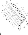
- Fig. 1 is a perspective view showing a circumferential groove 3 of a tire 1 as an embodiment of the present invention
- Fig. 2 is a partial top view of the circumferential groove 3.
- the tire 1 comprises a tread portion 2 whose radially outer surface defines a tread surface 2a contacting with the ground.
- the tread portion 2 is provided with at least one circumferential groove 3 continuously extending in the tire circumferential direction, and a plurality of land portions 4 divided by the circumferential groove 3.
- Fig. 3 is a cross-sectional view taken along line A-A of Fig. 2 .
- Fig. 4 is a cross-sectional view taken along line B-B of Fig. 2 .
- Fig. 5 is a cross-sectional perspective view of the circumferential groove 3 of Fig. 1 .
- the circumferential groove 3 has a groove bottom 5 and a pair of groove walls 6 extending in a tire radial direction from the groove bottom 5 toward the tread surface 2a.
- an expression "(an object) extends in a direction” means that (the object) has a component which is largest in the above-said direction.
- the groove bottom 5 is provided with groove bottom raised portions 7 which protrude radially outwardly from a groove bottom reference plane 5a, wherein the groove bottom reference plane 5a is defined by a plane being parallel to the tread surface 2a and positioned at the deepest point of the groove depth D of the circumferential groove 3.
- the groove bottom raised portions 7 include a first groove bottom raised portion 7A located on a first side s1 in the width direction of the circumferential groove 3, and a second groove bottom raised portion 7B located on a second side s2 in the width direction of the circumferential groove 3.
- Each of the first groove bottom raised portion 7A and the second groove bottom raised portion 7B comprises a plurality of repeating units 10 each comprising a first bottom surface 8 extending substantially in the tire radial direction, and a second bottom surface 8 inclined with respect to the tire radial direction at a larger angle than the first bottom surface 8.
- the expression "(a surface) extends substantially in the tire radial direction” means that (the surface) may be inclined at an angle in a range from -10 degrees to +10 degrees with respect to the tire radial direction.
- the compressing of the snow in the circumferential groove is furthered, and the shear force of the compressed snow block is increased even when the tire 1 is worn.
- the inclination direction of the second bottom surfaces 9 of the first groove bottom raised portion 7A is opposite to the inclination direction of the second bottom surfaces 9 of the second groove bottom raised portion 7B.
- Such groove bottom raised portions 7A and 7B can exert comparable on-snow performance, regardless of the direction of rotation of the tire 1. Further, both the driving force and the braking force at the time of running on snow can be improved. Thus, regardless of the direction of rotation of the tire 1, the on-snow performance can be improved.
- first bottom surfaces 8 of the first groove bottom raised portion 7A are respectively disposed at the same positions in the tire circumferential direction as the first bottom surfaces 8 of the second groove bottom raised portion 7B.
- Such groove bottom raised portions 7A and 7B ensure that the first bottom surfaces 8 of the first groove bottom raised portion 7A and the first bottom surfaces 8 of the second groove bottom raised portion 7B simultaneously bite into the snow, which further improve the on-snow performance of the tire 1.
- each of the first bottom surface 8 and the second bottom surface 9 is a flat surface.
- one of or each of the first bottom surface 8 and the second bottom surface 9 may be a curved surface, or a combination of a plurality of flat surfaces.
- the border between the first groove bottom raised portion 7A and the second groove bottom raised portion 7B is positioned on the widthwise center line 3c of the circumferential groove 3 in the top view thereof as shown in Fig. 2 .
- Such groove bottom raised portions 7A and 7B can exert comparable on-snow performance regardless of the direction of rotation of the tire 1 because the first groove bottom raised portions 7A and the second groove bottom raised portions 7B are arranged evenly in the widthwise direction, more specifically, arranged in 180-degree rotational symmetry.
- the boundary between the first groove bottom raised portion 7A and the second groove bottom raised portion 7B may be set at a position different from the widthwise center line 3c of the circumferential groove 3 in the top view.
- the protruding height H in the tire radial direction from the groove bottom reference plane 5a of the first bottom surfaces 8 (or the second bottom surfaces 9) is preferably not less than 1 mm. If the protruding height H is smaller than 1 mm, the effect of compressing the snow in the circumferential groove 3 may be reduced, and the shear force of the compressed snow block for exerting the driving force may not be increased.
- the protruding height H is smaller than the height in the tire radial direction from the groove bottom reference plane 5a of a tread wear indicator (not shown) provided in the circumferential groove 3 to indicate the wear limit of the tire 1.
- the groove bottom raised portions 7 having such groove bottom configuration ensures that, even when the tread portion is worn up to the wear limit of the tire 1, the first bottom surfaces 8 bite into the snow in the circumferential groove, and the tire 1 can maintain good on-snow performance.
- the protruding height H of the first bottom surfaces 8 is preferably set to be not less than 3% of the distance Lb in the tire circumferential direction between the first bottom surfaces 8 adjacent in the tire circumferential direction. Thereby, the first bottom surfaces 8 bite into the snow appropriately and exert a large driving force. Thus, the on-snow performance of the tire 1 can be improved.
- the pair of groove walls 6 are a first groove wall 6A located on the first side s1, and a second groove wall 6B located on the second side s2.
- first groove wall 6A and the second groove wall 6B is provided with a groove wall protruding portion 11 protruding inward of the circumferential groove 3 from a groove wall reference plane 6a.
- the groove wall reference plane 6a is defined by a plane being parallel to the tire circumferential direction and positioned at the widest position of the groove width w of the circumferential groove 3.
- the groove wall protruding portion 11 bites into the snow therein, and the on-snow performance can be improved.
- the groove wall protruding portion 11 can disturb vibrations of the air in the circumferential groove 3 and reduce the air resonance noise during running, the noise performance of the tire 1 can be improved.
- the groove wall protruding portion 11 comprises a plurality of repeating units 14 each comprising a first wall surface 12 extending in the tire widthwise direction, and a second wall surfaces 13 inclined with respect to the tire widthwise direction at an angle larger than the first wall surface 12.
- the groove wall 6 having such groove wall protruding portion 11 can improve the driving force and the braking force when running on snow because the first wall surfaces 12 increase the component in the tire widthwise direction of the groove edge.
- the snow moved along and relatively to the second wall surface 13 is compressed, and increased in the shear force.
- the tire 1 of the present embodiment can be further improved in the on-the-snow performance as the groove bottom raised portions 7 bite into the snow compressed by the groove wall 6.
- such circumferential groove 3 can further improve the on-snow performance because, when a portion of the circumferential groove 3 enters into the ground contacting patch and then goes out thereof during running, the groove bottom raised portion 7 and the groove wall protruding portion 11 in this portion are deformed, and self-ejection of the snow from the circumferential groove 3 is induced.
- the first wall surfaces 12 are respectively disposed at the same positions in the tire circumferential direction as the first bottom surfaces 8.
- Such circumferential groove 3 can more effectively improve the on-snow performance owing to the groove bottom raised portions 7 biting into the snow compressed by the groove walls 6.
- each of the first wall surface 12 and the second wall surface 13 is a flat surface.
- the second wall surfaces 13 of the first groove wall 6A are substantially parallel to the second wall surfaces 13 of the second groove wall 6B in the top view of the circumferential groove 3 as shown in Fig. 2 .
- the groove wall protruding portion 11 can exert comparable on-snow performance regardless of the direction of rotation of the tire 1.
- the expression "(an object is) substantially parallel (to another object)" means that the angular difference between the objects is at most 5 degrees.
- the protruding amount WL in the tire widthwise direction of the first wall surfaces 12 from the groove wall reference plane 6a is not less than 1 mm. If the protruding amount WL is smaller than 1 mm, the effect of compressing the snow existing in the circumferential groove 3 may be reduced, and the shear force of the compressed snow block for exerting the driving force may not be increased.
- the protruding amount WL of the first wall surfaces 12 is not less than 3% of the distance Lw in the tire circumferential direction between the first wall surfaces 12 adjacent in the tire circumferential direction.
- the groove wall protruding portion 11 having such first wall surfaces 12 can improve the on-snow performance of the tire 1 since the first wall surfaces 12 can appropriately bite into the snow to exert a large driving force.
- the distance Lw in the tire circumferential direction between the first wall surfaces 12 is equal to the distance Lb in the tire circumferential direction between the first bottom surfaces 8 adjacent in the tire circumferential direction.
- the tire 1 having such circumferential grooves 3 can provide good on-snow performance under both conditions of the tire 1 being not worn and worn.
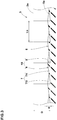
- Fig. 6 shows a circumferential groove 20 of another embodiment of the tire 1.
- the circumferential groove 20 has a groove bottom 22 provided with groove bottom raised portions 21, and a pair of groove walls 23 extending in the tire radial direction from the groove bottom 22 toward the tread surface 2a.
- the groove bottom raised portions 21 include a first groove bottom raised portion 21A located on the first side s1 in the width direction of the circumferential groove 20, and a second groove bottom raised portion 21B located on the second side s2 in the width direction.
- each of the first groove bottom protruding portion 21A and the second groove bottom protruding portion 21B comprises a plurality of repeating units 26 each comprising a first bottom surface 24 extending in the tire radial direction, and a second bottom surface inclined with respect to the tire radial direction at a larger angle than the first bottom surface 24.
- each of the first bottom surface 24 and the second bottom surface 25 is a flat surface.
- first bottom surfaces 24 of the first groove bottom raised portion 21A are disposed at different circumferential positions from the first bottom surfaces 24 of the second groove bottom raised portion 21B.
- Such groove bottom raised portions 21A and 21B can form a passage extending across the boundary between the first groove bottom raised portion 21A and the second groove bottom raised portion 21B. Therefore, in the circumferential groove 20 of the present embodiment, water can flow smoothly along the groove bottom 22 through this passage, so the wet performance is improved, and the effect of suppressing the hydroplaning phenomenon is exhibited,
- first bottom surfaces 24 of the first groove bottom raised portion 21A are disposed at respective intermediate positions in the tire circumferential direction between the first bottom surfaces 24 of the second groove bottom raised portions 21B.
- the boundary between the first groove bottom raised portions 21A and the second groove bottom raised portions 21B is positioned on the widthwise center line 20c of the circumferential groove 20 in the top view thereof as shown in Fig. 6 .
- Such groove bottom raised portions 21A and 21B exhibits comparable on-snow performance regardless of the direction of rotation of the tire 1 since the first groove bottom raised portion 21A and the second groove bottom raised portion 21B are arranged evenly in the widthwise direction, more specifically, arranged in 180-degree rotational symmetry.
- the pair of groove walls 23 are a first groove wall 23A located on the first side s1 and a second groove wall 23B located on the second side s2.
- first groove wall 23A and the second groove wall 23B is provided with a groove wall protruding portion 27 protruding inward of the circumferential groove 20 from a groove wall reference plane 23a.
- the groove wall reference plane 23a is defined by a plane being parallel to the tire circumferential direction and positioned at the widest position of the groove width w of the circumferential groove 20.
- the groove wall protruding portion 27 comprises a plurality of repeating units 30 each comprising a first wall surface 28 extending in the tire widthwise direction, and a second wall surface 29 inclined with respect to the tire widthwise direction at a larger angle than the first wall surface 28.
- each of the first wall surface 28 and the second wall surface 29 is a flat surface.
- first wall surfaces 28 of the first groove wall 23A are respectively disposed at the same positions in the tire circumferential direction as the first bottom surfaces 24 of the first groove bottom raised portions 21A.
- first wall surfaces 28 of the second groove wall 23B are respectively disposed at the same positions in the tire circumferential direction as the first bottom surfaces 24 of the second groove bottom raised portions 21B.
- Such circumferential groove 20 can more effectively improve the on-snow performance owing to the groove bottom raised portions 21 biting into the snow compressed by the groove walls 23A and 23B.
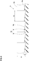
- Fig. 7 shows a circumferential groove 40 of still another embodiment of the tire 1.
- the circumferential groove 40 has a groove bottom 42 provided with groove bottom raised portions 41, and a pair of groove walls 43 extending in the tire radial direction from the groove bottom 42 toward the tread surface 2a.
- the groove bottom raised portions 41 are a first groove bottom raised portion 41A located on the first side s1 in the width direction of the circumferential groove 40, and a second groove bottom raised portion 41B located on the second side s2 in the width direction of the circumferential groove 40.
- each of the first groove bottom raised portion 41A and the second groove bottom raised portion 41B comprises a plurality of repeating units 46 each comprising a first bottom surface 44 extending in the tire radial direction, and a second bottom surface 45 inclined with respect to the tire radial direction at a larger angle than the first bottom surface 44.
- each of the first bottom surface 44 and the second bottom surface 45 is a flat surface.
- the border between the first groove bottom raised portion 41A and the second groove bottom raised portion 41B is positioned on the widthwise center line 40c of the circumferential groove 40 in the top view thereof as shown in Fig. 7 .
- Such groove bottom raised portions 41 exhibit comparable on-snow performance regardless of the direction of rotation of the tire 1 since the first groove bottom raised portion 41A and the second groove bottom raised portion 41B are arranged evenly in the widthwise direction, more specifically, arranged in 180-degree rotational symmetry.
- the pair of groove walls 43 are a first groove wall 43A located on the first side s1 and a second groove wall 43B located on the second side s2.
- first groove wall 43A and the second groove wall 43B is provided with a groove wall protruding portion 47 protruding inward of the circumferential groove 40 from a groove wall reference plane 43a.
- the groove wall reference plane 43a is defined by a plane being parallel to the tire circumferential direction and positioned at the widest position of the groove width w of the circumferential groove 40.
- the groove wall protruding portion 47 comprises a plurality of repeating units 50 each comprising a first wall surface 48 extending in the tire widthwise direction and a second wall surface 49 inclined with respect to the tire widthwise direction at a larger angle than the first wall surface 48.
- the first wall surface 48 is a flat surface
- the second wall surface 49 is a curved surface.
- the second wall surface 49 is curved convexly toward the inside of the circumferential groove 40 as shown in Fig. 7 . But, it may be curved concavely.
- Pneumatic tires of size 255/55R17 were experimentally manufactured as test tires (practical example Ex1, practical Example Ex2 and comparative example Ref).
- the practical example Ex1 was provided with a plurality of the circumferential grooves 3 having the groove bottom raised portions 7A and 7B and the groove wall protruding portions 11 shown in Figs. 1 to 5 .
- the practical example Ex2 was provided with a plurality of the circumferential grooves 20 having the groove bottom raised portions 21A and 21B and the groove wall protruding portions 27 shown in Fig. 6 .
- the comparative example Ref was provided with a plurality of circumferential grooves not having the groove bottom raised portion and the groove wall protruding portion.
- test tires were not worn (namely, new) and the test tires were worn to 50% of the wear limit, each test tire was tested for on-snow performance when running on snow, wet performance when running on a wet road, and noise performance when running on a dry road by the use of a medium-sized passenger car whose all wheels had the same test tires inflated to 230 kPa.
- test driver evaluated wet performance of each test tire.
- the results are indicated in Table 1 by an index based on the comparative example being 100, wherein the larger the value, the better the wet performance.
- the tires according to the present invention were superior in the on-snow performance to the comparative example tire, and maintained good on-snow performance even under the worn condition. Further, it was confirmed that the tires according to the present invention maintained the wet performance comparable to the comparative example tire, and the tire Ex2 maintained the same wet performance even under the worn condition. Furthermore, it was confirmed that, as compared with the comparative example tire, the tires according to the present invention were superior in the noise performance when running on dry roads, and the air resonance noise was reduced.
Applications Claiming Priority (1)
| Application Number | Priority Date | Filing Date | Title |
|---|---|---|---|
| JP2018098171A JP7087671B2 (ja) | 2018-05-22 | 2018-05-22 | タイヤ |
Publications (2)
| Publication Number | Publication Date |
|---|---|
| EP3572244A1 true EP3572244A1 (de) | 2019-11-27 |
| EP3572244B1 EP3572244B1 (de) | 2021-04-07 |
Family
ID=66379756
Family Applications (1)
| Application Number | Title | Priority Date | Filing Date |
|---|---|---|---|
| EP19172217.2A Active EP3572244B1 (de) | 2018-05-22 | 2019-05-02 | Reifen |
Country Status (3)
| Country | Link |
|---|---|
| US (1) | US11633990B2 (de) |
| EP (1) | EP3572244B1 (de) |
| JP (1) | JP7087671B2 (de) |
Families Citing this family (1)
| Publication number | Priority date | Publication date | Assignee | Title |
|---|---|---|---|---|
| JP7310314B2 (ja) * | 2019-05-31 | 2023-07-19 | 住友ゴム工業株式会社 | タイヤ |
Citations (3)
| Publication number | Priority date | Publication date | Assignee | Title |
|---|---|---|---|---|
| JP2005231600A (ja) * | 2004-02-23 | 2005-09-02 | Yokohama Rubber Co Ltd:The | 空気入りタイヤおよびその製造金型 |
| EP2985157A1 (de) * | 2013-04-12 | 2016-02-17 | Bridgestone Corporation | Flugzeugreifen |
| JP2016137763A (ja) | 2015-01-26 | 2016-08-04 | 横浜ゴム株式会社 | 空気入りタイヤ |
Family Cites Families (6)
| Publication number | Priority date | Publication date | Assignee | Title |
|---|---|---|---|---|
| US6415835B1 (en) * | 2000-06-08 | 2002-07-09 | The Goodyear Tire & Rubber Company | Pneumatic tire tread having groove with peaks and valleys |
| JP2002036820A (ja) * | 2000-07-24 | 2002-02-06 | Bridgestone Corp | 空気入りタイヤ |
| JP4500320B2 (ja) * | 2007-02-07 | 2010-07-14 | 東洋ゴム工業株式会社 | 空気入りタイヤ |
| ES2571030T3 (es) * | 2007-03-12 | 2016-05-23 | Bridgestone Corp | Neumático |
| US20090194212A1 (en) * | 2008-02-01 | 2009-08-06 | Mark Leonard Bonko | Tire tread discharge grooves with textured bases |
| US10017013B2 (en) * | 2013-04-25 | 2018-07-10 | Bridgestone Corporation | Aircraft tire including tread with groove recesses for suppressing heat generation |
-
2018
- 2018-05-22 JP JP2018098171A patent/JP7087671B2/ja active Active
-
2019
- 2019-05-02 EP EP19172217.2A patent/EP3572244B1/de active Active
- 2019-05-21 US US16/417,991 patent/US11633990B2/en active Active
Patent Citations (3)
| Publication number | Priority date | Publication date | Assignee | Title |
|---|---|---|---|---|
| JP2005231600A (ja) * | 2004-02-23 | 2005-09-02 | Yokohama Rubber Co Ltd:The | 空気入りタイヤおよびその製造金型 |
| EP2985157A1 (de) * | 2013-04-12 | 2016-02-17 | Bridgestone Corporation | Flugzeugreifen |
| JP2016137763A (ja) | 2015-01-26 | 2016-08-04 | 横浜ゴム株式会社 | 空気入りタイヤ |
Also Published As
| Publication number | Publication date |
|---|---|
| EP3572244B1 (de) | 2021-04-07 |
| JP2019202607A (ja) | 2019-11-28 |
| US20190359008A1 (en) | 2019-11-28 |
| US11633990B2 (en) | 2023-04-25 |
| JP7087671B2 (ja) | 2022-06-21 |
Similar Documents
| Publication | Publication Date | Title |
|---|---|---|
| US9085201B2 (en) | Pneumatic tire | |
| US10328751B2 (en) | Pneumatic tire | |
| US8925602B2 (en) | Pneumatic tire | |
| AU2014227282B2 (en) | Pneumatic tire | |
| US9302553B2 (en) | Pneumatic tire | |
| JP5265554B2 (ja) | 空気入りタイヤ | |
| CN110722934B (zh) | 车辆轮胎 | |
| US8967210B2 (en) | Pneumatic tire with tread having zigzag sipes and narrow grooves | |
| RU2388617C1 (ru) | Пневматическая шина | |
| RU2733030C2 (ru) | Шина | |
| US20060118222A1 (en) | Pneumatic tire | |
| US20150375572A1 (en) | Pneumatic Tire | |
| US11279178B2 (en) | Tire | |
| US10232670B2 (en) | Pneumatic tire | |
| US20180339557A1 (en) | Tire | |
| EP3572244B1 (de) | Reifen | |
| US20220219491A1 (en) | Pneumatic Tire | |
| US11225109B2 (en) | Tyre | |
| JPH1024707A (ja) | 氷雪路用空気入りタイヤ | |
| US20190225023A1 (en) | Tire | |
| EP3446891B1 (de) | Reifen und reifengussform | |
| US11807045B2 (en) | Tire with hybrid sipe pattern | |
| US20220258539A1 (en) | Tyre | |
| JP2021091362A (ja) | 空気入りタイヤ |
Legal Events
| Date | Code | Title | Description |
|---|---|---|---|
| PUAI | Public reference made under article 153(3) epc to a published international application that has entered the european phase |
Free format text: ORIGINAL CODE: 0009012 |
|
| STAA | Information on the status of an ep patent application or granted ep patent |
Free format text: STATUS: THE APPLICATION HAS BEEN PUBLISHED |
|
| AK | Designated contracting states |
Kind code of ref document: A1 Designated state(s): AL AT BE BG CH CY CZ DE DK EE ES FI FR GB GR HR HU IE IS IT LI LT LU LV MC MK MT NL NO PL PT RO RS SE SI SK SM TR |
|
| AX | Request for extension of the european patent |
Extension state: BA ME |
|
| STAA | Information on the status of an ep patent application or granted ep patent |
Free format text: STATUS: REQUEST FOR EXAMINATION WAS MADE |
|
| 17P | Request for examination filed |
Effective date: 20200320 |
|
| RBV | Designated contracting states (corrected) |
Designated state(s): AL AT BE BG CH CY CZ DE DK EE ES FI FR GB GR HR HU IE IS IT LI LT LU LV MC MK MT NL NO PL PT RO RS SE SI SK SM TR |
|
| RIC1 | Information provided on ipc code assigned before grant |
Ipc: B60C 11/13 20060101AFI20200918BHEP Ipc: B60C 11/04 20060101ALI20200918BHEP Ipc: B60C 11/03 20060101ALI20200918BHEP |
|
| GRAP | Despatch of communication of intention to grant a patent |
Free format text: ORIGINAL CODE: EPIDOSNIGR1 |
|
| STAA | Information on the status of an ep patent application or granted ep patent |
Free format text: STATUS: GRANT OF PATENT IS INTENDED |
|
| INTG | Intention to grant announced |
Effective date: 20201104 |
|
| GRAJ | Information related to disapproval of communication of intention to grant by the applicant or resumption of examination proceedings by the epo deleted |
Free format text: ORIGINAL CODE: EPIDOSDIGR1 |
|
| STAA | Information on the status of an ep patent application or granted ep patent |
Free format text: STATUS: REQUEST FOR EXAMINATION WAS MADE |
|
| GRAP | Despatch of communication of intention to grant a patent |
Free format text: ORIGINAL CODE: EPIDOSNIGR1 |
|
| STAA | Information on the status of an ep patent application or granted ep patent |
Free format text: STATUS: GRANT OF PATENT IS INTENDED |
|
| INTC | Intention to grant announced (deleted) | ||
| GRAS | Grant fee paid |
Free format text: ORIGINAL CODE: EPIDOSNIGR3 |
|
| GRAA | (expected) grant |
Free format text: ORIGINAL CODE: 0009210 |
|
| STAA | Information on the status of an ep patent application or granted ep patent |
Free format text: STATUS: THE PATENT HAS BEEN GRANTED |
|
| INTG | Intention to grant announced |
Effective date: 20210219 |
|
| RIN1 | Information on inventor provided before grant (corrected) |
Inventor name: NAKAJIMA, KOICHI |
|
| AK | Designated contracting states |
Kind code of ref document: B1 Designated state(s): AL AT BE BG CH CY CZ DE DK EE ES FI FR GB GR HR HU IE IS IT LI LT LU LV MC MK MT NL NO PL PT RO RS SE SI SK SM TR |
|
| REG | Reference to a national code |
Ref country code: GB Ref legal event code: FG4D |
|
| REG | Reference to a national code |
Ref country code: AT Ref legal event code: REF Ref document number: 1379207 Country of ref document: AT Kind code of ref document: T Effective date: 20210415 Ref country code: CH Ref legal event code: EP |
|
| REG | Reference to a national code |
Ref country code: DE Ref legal event code: R096 Ref document number: 602019003697 Country of ref document: DE |
|
| REG | Reference to a national code |
Ref country code: IE Ref legal event code: FG4D |
|
| REG | Reference to a national code |
Ref country code: LT Ref legal event code: MG9D |
|
| REG | Reference to a national code |
Ref country code: NL Ref legal event code: MP Effective date: 20210407 Ref country code: AT Ref legal event code: MK05 Ref document number: 1379207 Country of ref document: AT Kind code of ref document: T Effective date: 20210407 |
|
| PG25 | Lapsed in a contracting state [announced via postgrant information from national office to epo] |
Ref country code: FI Free format text: LAPSE BECAUSE OF FAILURE TO SUBMIT A TRANSLATION OF THE DESCRIPTION OR TO PAY THE FEE WITHIN THE PRESCRIBED TIME-LIMIT Effective date: 20210407 Ref country code: LT Free format text: LAPSE BECAUSE OF FAILURE TO SUBMIT A TRANSLATION OF THE DESCRIPTION OR TO PAY THE FEE WITHIN THE PRESCRIBED TIME-LIMIT Effective date: 20210407 Ref country code: HR Free format text: LAPSE BECAUSE OF FAILURE TO SUBMIT A TRANSLATION OF THE DESCRIPTION OR TO PAY THE FEE WITHIN THE PRESCRIBED TIME-LIMIT Effective date: 20210407 Ref country code: BG Free format text: LAPSE BECAUSE OF FAILURE TO SUBMIT A TRANSLATION OF THE DESCRIPTION OR TO PAY THE FEE WITHIN THE PRESCRIBED TIME-LIMIT Effective date: 20210707 Ref country code: AT Free format text: LAPSE BECAUSE OF FAILURE TO SUBMIT A TRANSLATION OF THE DESCRIPTION OR TO PAY THE FEE WITHIN THE PRESCRIBED TIME-LIMIT Effective date: 20210407 Ref country code: NL Free format text: LAPSE BECAUSE OF FAILURE TO SUBMIT A TRANSLATION OF THE DESCRIPTION OR TO PAY THE FEE WITHIN THE PRESCRIBED TIME-LIMIT Effective date: 20210407 |
|
| PG25 | Lapsed in a contracting state [announced via postgrant information from national office to epo] |
Ref country code: IS Free format text: LAPSE BECAUSE OF FAILURE TO SUBMIT A TRANSLATION OF THE DESCRIPTION OR TO PAY THE FEE WITHIN THE PRESCRIBED TIME-LIMIT Effective date: 20210807 Ref country code: GR Free format text: LAPSE BECAUSE OF FAILURE TO SUBMIT A TRANSLATION OF THE DESCRIPTION OR TO PAY THE FEE WITHIN THE PRESCRIBED TIME-LIMIT Effective date: 20210708 Ref country code: PL Free format text: LAPSE BECAUSE OF FAILURE TO SUBMIT A TRANSLATION OF THE DESCRIPTION OR TO PAY THE FEE WITHIN THE PRESCRIBED TIME-LIMIT Effective date: 20210407 Ref country code: LV Free format text: LAPSE BECAUSE OF FAILURE TO SUBMIT A TRANSLATION OF THE DESCRIPTION OR TO PAY THE FEE WITHIN THE PRESCRIBED TIME-LIMIT Effective date: 20210407 Ref country code: NO Free format text: LAPSE BECAUSE OF FAILURE TO SUBMIT A TRANSLATION OF THE DESCRIPTION OR TO PAY THE FEE WITHIN THE PRESCRIBED TIME-LIMIT Effective date: 20210707 Ref country code: RS Free format text: LAPSE BECAUSE OF FAILURE TO SUBMIT A TRANSLATION OF THE DESCRIPTION OR TO PAY THE FEE WITHIN THE PRESCRIBED TIME-LIMIT Effective date: 20210407 Ref country code: PT Free format text: LAPSE BECAUSE OF FAILURE TO SUBMIT A TRANSLATION OF THE DESCRIPTION OR TO PAY THE FEE WITHIN THE PRESCRIBED TIME-LIMIT Effective date: 20210809 Ref country code: SE Free format text: LAPSE BECAUSE OF FAILURE TO SUBMIT A TRANSLATION OF THE DESCRIPTION OR TO PAY THE FEE WITHIN THE PRESCRIBED TIME-LIMIT Effective date: 20210407 |
|
| REG | Reference to a national code |
Ref country code: DE Ref legal event code: R097 Ref document number: 602019003697 Country of ref document: DE |
|
| PG25 | Lapsed in a contracting state [announced via postgrant information from national office to epo] |
Ref country code: SK Free format text: LAPSE BECAUSE OF FAILURE TO SUBMIT A TRANSLATION OF THE DESCRIPTION OR TO PAY THE FEE WITHIN THE PRESCRIBED TIME-LIMIT Effective date: 20210407 Ref country code: EE Free format text: LAPSE BECAUSE OF FAILURE TO SUBMIT A TRANSLATION OF THE DESCRIPTION OR TO PAY THE FEE WITHIN THE PRESCRIBED TIME-LIMIT Effective date: 20210407 Ref country code: ES Free format text: LAPSE BECAUSE OF FAILURE TO SUBMIT A TRANSLATION OF THE DESCRIPTION OR TO PAY THE FEE WITHIN THE PRESCRIBED TIME-LIMIT Effective date: 20210407 Ref country code: LU Free format text: LAPSE BECAUSE OF NON-PAYMENT OF DUE FEES Effective date: 20210502 Ref country code: DK Free format text: LAPSE BECAUSE OF FAILURE TO SUBMIT A TRANSLATION OF THE DESCRIPTION OR TO PAY THE FEE WITHIN THE PRESCRIBED TIME-LIMIT Effective date: 20210407 Ref country code: CZ Free format text: LAPSE BECAUSE OF FAILURE TO SUBMIT A TRANSLATION OF THE DESCRIPTION OR TO PAY THE FEE WITHIN THE PRESCRIBED TIME-LIMIT Effective date: 20210407 Ref country code: RO Free format text: LAPSE BECAUSE OF FAILURE TO SUBMIT A TRANSLATION OF THE DESCRIPTION OR TO PAY THE FEE WITHIN THE PRESCRIBED TIME-LIMIT Effective date: 20210407 Ref country code: MC Free format text: LAPSE BECAUSE OF FAILURE TO SUBMIT A TRANSLATION OF THE DESCRIPTION OR TO PAY THE FEE WITHIN THE PRESCRIBED TIME-LIMIT Effective date: 20210407 Ref country code: SM Free format text: LAPSE BECAUSE OF FAILURE TO SUBMIT A TRANSLATION OF THE DESCRIPTION OR TO PAY THE FEE WITHIN THE PRESCRIBED TIME-LIMIT Effective date: 20210407 |
|
| REG | Reference to a national code |
Ref country code: BE Ref legal event code: MM Effective date: 20210531 |
|
| PLBE | No opposition filed within time limit |
Free format text: ORIGINAL CODE: 0009261 |
|
| STAA | Information on the status of an ep patent application or granted ep patent |
Free format text: STATUS: NO OPPOSITION FILED WITHIN TIME LIMIT |
|
| 26N | No opposition filed |
Effective date: 20220110 |
|
| PG25 | Lapsed in a contracting state [announced via postgrant information from national office to epo] |
Ref country code: IE Free format text: LAPSE BECAUSE OF NON-PAYMENT OF DUE FEES Effective date: 20210502 |
|
| PG25 | Lapsed in a contracting state [announced via postgrant information from national office to epo] |
Ref country code: IS Free format text: LAPSE BECAUSE OF FAILURE TO SUBMIT A TRANSLATION OF THE DESCRIPTION OR TO PAY THE FEE WITHIN THE PRESCRIBED TIME-LIMIT Effective date: 20210807 Ref country code: AL Free format text: LAPSE BECAUSE OF FAILURE TO SUBMIT A TRANSLATION OF THE DESCRIPTION OR TO PAY THE FEE WITHIN THE PRESCRIBED TIME-LIMIT Effective date: 20210407 |
|
| PG25 | Lapsed in a contracting state [announced via postgrant information from national office to epo] |
Ref country code: IT Free format text: LAPSE BECAUSE OF FAILURE TO SUBMIT A TRANSLATION OF THE DESCRIPTION OR TO PAY THE FEE WITHIN THE PRESCRIBED TIME-LIMIT Effective date: 20210407 Ref country code: BE Free format text: LAPSE BECAUSE OF NON-PAYMENT OF DUE FEES Effective date: 20210531 |
|
| REG | Reference to a national code |
Ref country code: CH Ref legal event code: PL |
|
| PG25 | Lapsed in a contracting state [announced via postgrant information from national office to epo] |
Ref country code: LI Free format text: LAPSE BECAUSE OF NON-PAYMENT OF DUE FEES Effective date: 20220531 Ref country code: CH Free format text: LAPSE BECAUSE OF NON-PAYMENT OF DUE FEES Effective date: 20220531 |
|
| P01 | Opt-out of the competence of the unified patent court (upc) registered |
Effective date: 20230510 |
|
| PG25 | Lapsed in a contracting state [announced via postgrant information from national office to epo] |
Ref country code: CY Free format text: LAPSE BECAUSE OF FAILURE TO SUBMIT A TRANSLATION OF THE DESCRIPTION OR TO PAY THE FEE WITHIN THE PRESCRIBED TIME-LIMIT Effective date: 20210407 |
|
| PG25 | Lapsed in a contracting state [announced via postgrant information from national office to epo] |
Ref country code: HU Free format text: LAPSE BECAUSE OF FAILURE TO SUBMIT A TRANSLATION OF THE DESCRIPTION OR TO PAY THE FEE WITHIN THE PRESCRIBED TIME-LIMIT; INVALID AB INITIO Effective date: 20190502 |
|
| PGFP | Annual fee paid to national office [announced via postgrant information from national office to epo] |
Ref country code: FR Payment date: 20230411 Year of fee payment: 5 Ref country code: DE Payment date: 20230331 Year of fee payment: 5 |
|
| GBPC | Gb: european patent ceased through non-payment of renewal fee |
Effective date: 20230502 |
|
| PG25 | Lapsed in a contracting state [announced via postgrant information from national office to epo] |
Ref country code: MK Free format text: LAPSE BECAUSE OF FAILURE TO SUBMIT A TRANSLATION OF THE DESCRIPTION OR TO PAY THE FEE WITHIN THE PRESCRIBED TIME-LIMIT Effective date: 20210407 Ref country code: GB Free format text: LAPSE BECAUSE OF NON-PAYMENT OF DUE FEES Effective date: 20230502 |