EP3572151B1 - Mikrofluidische verbindung und verbindungsschnittstelle zum fluidischen verbinden von mikrofluidischen kanälen - Google Patents
Mikrofluidische verbindung und verbindungsschnittstelle zum fluidischen verbinden von mikrofluidischen kanälen Download PDFInfo
- Publication number
- EP3572151B1 EP3572151B1 EP19175985.1A EP19175985A EP3572151B1 EP 3572151 B1 EP3572151 B1 EP 3572151B1 EP 19175985 A EP19175985 A EP 19175985A EP 3572151 B1 EP3572151 B1 EP 3572151B1
- Authority
- EP
- European Patent Office
- Prior art keywords
- microfluidic channel
- slit
- microfluidic
- connecting interface
- substrate
- Prior art date
- Legal status (The legal status is an assumption and is not a legal conclusion. Google has not performed a legal analysis and makes no representation as to the accuracy of the status listed.)
- Active
Links
Images

Classifications
-
- B—PERFORMING OPERATIONS; TRANSPORTING
- B01—PHYSICAL OR CHEMICAL PROCESSES OR APPARATUS IN GENERAL
- B01L—CHEMICAL OR PHYSICAL LABORATORY APPARATUS FOR GENERAL USE
- B01L3/00—Containers or dishes for laboratory use, e.g. laboratory glassware; Droppers
- B01L3/50—Containers for the purpose of retaining a material to be analysed, e.g. test tubes
- B01L3/502—Containers for the purpose of retaining a material to be analysed, e.g. test tubes with fluid transport, e.g. in multi-compartment structures
- B01L3/5027—Containers for the purpose of retaining a material to be analysed, e.g. test tubes with fluid transport, e.g. in multi-compartment structures by integrated microfluidic structures, i.e. dimensions of channels and chambers are such that surface tension forces are important, e.g. lab-on-a-chip
- B01L3/502715—Containers for the purpose of retaining a material to be analysed, e.g. test tubes with fluid transport, e.g. in multi-compartment structures by integrated microfluidic structures, i.e. dimensions of channels and chambers are such that surface tension forces are important, e.g. lab-on-a-chip characterised by interfacing components, e.g. fluidic, electrical, optical or mechanical interfaces
-
- B—PERFORMING OPERATIONS; TRANSPORTING
- B01—PHYSICAL OR CHEMICAL PROCESSES OR APPARATUS IN GENERAL
- B01L—CHEMICAL OR PHYSICAL LABORATORY APPARATUS FOR GENERAL USE
- B01L2200/00—Solutions for specific problems relating to chemical or physical laboratory apparatus
- B01L2200/02—Adapting objects or devices to another
- B01L2200/026—Fluid interfacing between devices or objects, e.g. connectors, inlet details
- B01L2200/027—Fluid interfacing between devices or objects, e.g. connectors, inlet details for microfluidic devices
-
- B—PERFORMING OPERATIONS; TRANSPORTING
- B01—PHYSICAL OR CHEMICAL PROCESSES OR APPARATUS IN GENERAL
- B01L—CHEMICAL OR PHYSICAL LABORATORY APPARATUS FOR GENERAL USE
- B01L2300/00—Additional constructional details
- B01L2300/08—Geometry, shape and general structure
-
- B—PERFORMING OPERATIONS; TRANSPORTING
- B01—PHYSICAL OR CHEMICAL PROCESSES OR APPARATUS IN GENERAL
- B01L—CHEMICAL OR PHYSICAL LABORATORY APPARATUS FOR GENERAL USE
- B01L2300/00—Additional constructional details
- B01L2300/08—Geometry, shape and general structure
- B01L2300/0809—Geometry, shape and general structure rectangular shaped
- B01L2300/0816—Cards, e.g. flat sample carriers usually with flow in two horizontal directions
-
- B—PERFORMING OPERATIONS; TRANSPORTING
- B01—PHYSICAL OR CHEMICAL PROCESSES OR APPARATUS IN GENERAL
- B01L—CHEMICAL OR PHYSICAL LABORATORY APPARATUS FOR GENERAL USE
- B01L2300/00—Additional constructional details
- B01L2300/08—Geometry, shape and general structure
- B01L2300/0861—Configuration of multiple channels and/or chambers in a single devices
-
- B—PERFORMING OPERATIONS; TRANSPORTING
- B01—PHYSICAL OR CHEMICAL PROCESSES OR APPARATUS IN GENERAL
- B01L—CHEMICAL OR PHYSICAL LABORATORY APPARATUS FOR GENERAL USE
- B01L3/00—Containers or dishes for laboratory use, e.g. laboratory glassware; Droppers
- B01L3/56—Labware specially adapted for transferring fluids
- B01L3/563—Joints or fittings ; Separable fluid transfer means to transfer fluids between at least two containers, e.g. connectors
Definitions
- This disclosure relates to interconnection of microfluidic channels.
- it relates to a connecting interface for fluidically interconnecting microfluidic channels, a microfluidic connection, and a diagnostic device including such a connecting interface or microfluidic connection.
- Microfluidics deals with the behavior, precise control and manipulation of fluids that are geometrically constrained to a small, typically sub-millimeter, scale.
- Technology based on microfluidics are used for example in ink-jet printer heads, DNA chips and within lab-on-a-chip technology.
- fluids are typically moved, mixed, separated or otherwise processed.
- passive fluid control is used. This may be realized by utilizing the capillary forces that arise within sub-millimeter tubes. By careful engineering of a so called capillary driven fluidic system, it may be possible to perform control and manipulation of fluids.
- Microfluidic substrates may be designed for different purposes, and it is often desirable to interconnect different microfluidic substrates to form part of a microfluidic system.
- a second microfluidic chip may be arranged on top of a cover of a first microfluidic chip, and the first and the second microfluidic chip may be fluidically connected via a through-hole in the cover.
- a through-hole connection has several drawbacks. Firstly, it is sensitive to misalignments of the microfluidic chips to be interconnected. Secondly, fluid will accumulate in the volume of the through-hole and hence reduce the fluid volume passed from the second chip to the first chip and vice versa. There is thus a need for improvements.
- the commercial product datasheet "6 Junction Droplet Chip” (XP055599503) from Dolomite Microfluidics discloses a glass microfluidic device designed for the parallel generation of droplets at 6 separate flow focussing junctions and wherein, to deliver fluid into all 6 inlet ports from a single pump, a 'Double Flow Splitting Manifold 7-way' is used.
- WO 2016/122643 A1 discloses a microfiuidic diagnostic chip, comprising a substrate; a plurality of fluidic slots extending through the substrate; a plurality of microfiuidic channels each coupled to a respective one of the plurality of fluidic slots.
- US 2007/048189 A1 discloses a fluid processing device, comprising: a substrate comprising a top surface; and a cover in contact with at least a portion of the top surface and comprising one or more slits forming slitted outlet regions.
- Example embodiments provide a connecting interface for fluidically interconnecting microfluidic channels.
- the connecting interface comprises one or more substrates which collectively define a first microfluidic channel which includes a connecting region for fluidically connecting the first microfluidic channel to a second microfluidic channel.
- the connecting interface further comprises at least one slit in an outer surface of one of the one or more substrates, wherein the at least one slit provides a fluid passage from the outer surface to the connecting region of the first microfluidic channel, and the at least one slit has at least one dimension extending beyond the connecting region along a direction parallel to the outer surface.
- example embodiments provide a connecting interface for fluidically interconnecting microfluidic channels, the connecting interface comprising one or more substrates which collectively define a first microfluidic channel which includes a connecting region for fluidically connecting the first microfluidic channel to a second microfluidic channel, and at least one slit in an outer surface of one of the one or more substrates, wherein the at least one slit provides a fluid passage from the outer surface to the connecting region of the first microfluidic channel, and the at least one slit has at least one dimension extending beyond the connecting region along a direction parallel to the outer surface.
- At least one slit is provided to establish a fluid passage from the outer surface to a connecting region of the first microfluidic channel. Since the at least one slit extends outside the connecting region of the microfluidic channel, the connecting interface is less sensitive to misalignments than a conventional through-hole connection. More specifically, a second microfluidic channel may be connected to the first microfluidic channel via the connection interface even if it is not perfectly aligned with the first microfluidic channel. It is enough that the second microfluidic channel overlaps with the at least one slit in the outer surface of the connecting interface. The at least one slit thus serves as an additional alignment tolerance since it extends outside the connecting region.
- a further advantage is that the at least one slit, due to its long and narrow shape, for a given alignment tolerance between mating microfluidic chips, has a reduced volume compared to a conventional through-hole connection. Accordingly, the fluid that is accumulated in the at least one slit is reduced compared to a conventional through-hole connection.
- a connecting region of a microfluidic channel is generally meant a region or portion of the microfluidic channel to be connected to another microfluidic channel.
- the connection may be an inlet, meaning that fluid is to be connected in to the microfluidic channel at the connecting region, or an outlet, meaning that fluid is to be connected out from the microfluidic channel at the connecting region.
- the first microfluidic channel and the at least one slit may be provided in different substrates. This is advantageous since it simplifies the fabrication of the connecting interface.
- the one or more substrates may comprise a first substrate which includes the first microfluidic channel, wherein the connecting region of the first microfluidic channel is arranged in a first surface of the first substrate, and a second substrate being arranged on the first surface, wherein said at least one slit is arranged in an outer surface of the second substrate to provide a fluid passage between the outer surface of the second substrate to the connecting region of the first microfluidic channel in the first substrate.
- the first microfluidic channel and the at least one slit may be defined in the same substrate.
- the first microfluidic channel and the at least one slit may be defined in opposite sides of the same substrate.
- the at least one slit may be a plurality of slits. By having a plurality of slits, the sensitivity to misalignment is further reduced. Having a plurality of slits may also reduce the flow resistance at the connection.
- the plurality of slits may be arranged in parallel.
- a longitudinal direction of the at least one slit may be parallel to longitudinal direction of the first microfluidic channel at the connecting region.
- the at least one slit serves as an extension of the first microfluidic channel, thereby making the microfluidic connection less sensitive to misalignments in the longitudinal direction of the first microfluidic channel.
- the longitudinal direction of the first microfluidic channel corresponds to the direction of flow in the first microfluidic channel.
- a longitudinal direction of the at least one slit may form an angle in relation to a longitudinal of the first microfluidic channel at the connecting region.
- the at least one slit may be orthogonal, or arranged at any other angle, to the first microfluidic channel. This makes the microfluidic connection less sensitive to misalignments in directions which forms an angle with respect to the first microfluidic channel.
- the first microfluidic channel may be branched into a plurality of sub-channels, wherein the connection region is defined by an intersection between the at least one slit and the plurality of sub-channels.
- the sub-channels may be arranged in parallel. This serves to reduce the flow resistance of the connection and allows for further misalignments of the second microfluidic channel with respect to the first microfluidic channel.
- each sub-channel of the plurality of sub-channels may be associated with a respective slit which provides a fluid passage between the outer surface and the sub-channel and which extends in a direction parallel to a longitudinal direction of the sub-channel.
- the plurality of slits may extend beyond the connecting region along radial directions in relation to a center of the connecting region. In that way, the connection becomes less sensitive to misalignments in several, radial, directions.
- the connecting region may have a circular shape in a cross-section parallel to the outer surface, and the plurality of slits may each extend beyond the circular shape along one of the radial directions.
- the first microfluidic channel may include a closed end, wherein the connecting region is arranged at the closed end.
- the first microfluidic channel may hence be connected to a second microfluidic channel at a closed end.
- the first microfluidic channel may form a chamber at the connecting region. More specifically, a portion of the first microfluidic channel may have a first width and a another portion of the first microfluidic channel outside the connecting region may have a second, smaller, width, such that the first microfluidic channel forms a chamber at the connection region. This may serve to reduce the flow resistance at the connection.
- the connecting region may include a micropillar array.
- a micropillar array may be arranged in the chamber mentioned above.
- a micropillar array serves to reduce the flow resistance at the connection while promoting strong capillary forces.
- a micropillar array may be used as an alternative to the sub-channels discussed above.
- the at least one slit has an elongated shape.
- a longitudinal direction of the at least one slit is parallel to the outer surface.
- the at least one slit may be straight.
- the at least one slit may be curved along the outer surface. Different shapes of the slits may have different advantages when it comes to reducing the sensitivity to misalignments and to reduce the flow resistance at the connection.
- example embodiments provide a microfluidic connection for fluidically interconnecting microfluidic channels, the microfluidic connection comprising the connecting interface according to the first aspect, and a further substrate including a second microfluidic channel arranged at said outer surface to intersect said at least one slit for fluidically connecting the second microfluidic channel to the first microfluidic channel.
- the microfluidic connection may further comprise an adhesive layer arranged between said outer surface and the further substrate, wherein the adhesive layer has an opening overlapping at least a portion of the at least one slit in the outer surface for fluidically connecting the first microfluidic channel to the second microfluidic channel.
- example embodiments provide a diagnostic device comprising the connecting interface according to the first aspect or the microfluidic connection according to the second aspect.
- the diagnostic device may be a device for detection of cells, proteins, small molecules and genetic material from body fluids.
- the second and third aspects may generally have the same features and advantages as the first aspect. It is further noted that the inventive concept relates to all possible combinations of features unless explicitly stated otherwise.
- Fig. 1A illustrates a microfluidic device 100.
- the microfluidic device 100 may comprise a microfluidic circuit.
- the microfluidic circuit may comprise various microfluidic components, including microfluidic channels, valves, flow resistors etc.
- the microfluidic components may be structures formed in a substrate, such as in a plastic, glass, or silicon.
- the illustrated microfluidic device 100 comprises a first microfluidic channel 102.
- the microfluidic channel 102 may be a capillary channel.
- the microfluidic device 100 further comprises an interface 104 for connecting the microfluidic device 100 to another microfluidic device.
- the interface 104 may be used to connect the first microfluidic channel 102 to a second microfluidic channel of the other microfluidic device.
- the interface 104 is arranged along the first microfluidic channel 102 at a region or portion thereof where it is to be connected to the second microfluidic channel. That region or portion is referred to herein as the "connecting region".
- the microfluidic device 100 may comprise several connecting interfaces 104.
- connecting interface 104a may be used to couple in a second microfluidic channel to the first microfluidic channel 102, while connecting interface 104b may be used to couple out the first microfluidic channel 102 to a third microfluidic channel.
- the connecting interface 104 may hence serve as an inlet to the first microfluidic channel 102 or as an outlet from the first microfluidic channel 102.
- the connecting interface 104 is schematically illustrated in Fig. 1B .
- the connecting interface 104 comprises the first microfluidic channel 102 and at least one slit 108.
- the connecting region 110 is defined as the intersection between the first microfluidic channel 102 and the at least one slit 108.
- the connecting interface 104 may be embodied in many different ways.
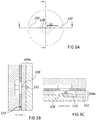
- Fig 1C shows a top view of the connecting interface 104.
- the first microfluidic channel 102 has a connecting region 110 (shown with a dotted pattern) where the first fluidic channel 102 is to be coupled to a second microfluidic channel.
- the first microfluidic channel 102 has a closed end 112, and the connecting region is 110 is arranged at the closed end 112.
- the connecting region 110 may be arranged anywhere along the first microfluidic channel 102. This applies to all embodiments shown herein.
- the at least one slit 108 extends beyond the connecting region 110 along the direction d1.
- the connecting interface 104 becomes less sensitive to misalignments when the first microfluidic device 100 is connected to another microfluidic device.
- the dimensions of the slit 108 may be on the order of 0.1 mm in width, 0.1 mm in depth and 1 mm in length and the length of the connecting region 110 may be on the order of 1 mm.
- five slits are shown which are arranged perpendicularly to a longitudinal direction of the first microfluidic channel 102.
- any number of slits (including a single slit) arranged at any angle in relation to the first microfluidic channel 102 may be used. This includes slits arranged in parallel with the longitudinal direction of the first microfluidic channel 102, arranged perpendicularly to the longitudinal direction of the first microfluidic channel 102, and any angle in between.
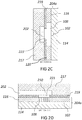
- the connecting interface 104 may be defined in one or more substrates. As shown in Figs 1D and 1E , which are cross-sections along the lines C-C and D-D of Fig. 1C , respectively, the first microfluidic channel 102 may be defined in a first substrate 114, while the at least one slit 108 may be defined in a second substrate 116. The second substrate 116 may be arranged on a first surface 118 of the first substrate 114 so as to form a lid or cover of the first substrate 114. The first microfluidic channel 102 may be imbedded in the first substrate 114. In particular, the first microfluidic channel 102 may be formed in the first surface 118.
- the at least one slit 108 is formed in an outer surface 120 of the second substrate 116.
- the outer surface 120 is opposite to the surface of the second substrate 116 facing the first surface 118.
- the at least one slit 108 forms a through-hole through the second substrate 116 extending from the outer surface 120 to the connecting region 110 of the first microfluidic channel 102 defined in the first surface 118.
- the at least one slit 108 hence provides a fluid passage from the outer surface 120 to the connecting region 110.
- the at least one slit 108 extends beyond the connecting region 110 of the first microfluidic channel 102 along direction d1 which is parallel to the outer surface 120.
- the first and the second substrate 114, 116 may be made of a variety of materials, such as silicon, glass, plastic, metal, etc.
- the first microfluidic channel 102 and the at least one slit 108 may be fabricated in the first and the second substrates using a suitable processing technique such as by chemical etching or mechanically by machining. This applies to all embodiments shown herein.
- the first microfluidic channel 102 and the at least one slit 108 may also be defined on the same substrate. Such an embodiment is illustrated in Figs 1F and 1G , which are cross-sections along the lines C-C and D-D of Fig. 1C . As shown, both the first microfluidic channel 102 and the at least one slit 108 are defined in the second substrate 116.
- the first substrate 114 serves as a base for the second substrate 116.
- the at least one slit 108 and the first microfluidic channel 102 are arranged in opposite surfaces of the second substrate 116.
- the at least one slit 108 is arranged in the outer surface 120, and the first microfluidic channel 102 is arranged in the surface facing the first surface 118 of the first substrate 114.
- the illustrated embodiments will be shown as being defined in two substrates, similarly to the embodiment of Figs 1D and 1E . However, it is understood that an implementation where the first microfluidic channel 102 and the at least one slit 108 are defined in the same substrate are equally possible.
- Fig. 2A illustrates a microfluidic connection between a first microfluidic device 100 and a second microfluidic device 200 arranged on the first microfluidic device 100.
- the second microfluidic device 200 includes a second microfluidic channel 202.
- the second microfluidic channel 202 is to be coupled into the first microfluidic channel 102.
- the illustrated second microfluidic device 200 further includes a third microfluidic channel 203 to which the first microfluidic channel 102 is to be coupled out.
- the microfluidic connection includes a first interconnection comprising a first connecting interface 204a for interconnecting the second microfluidic channel 202 and the first microfluidic channel 102.
- the microfluidic connection further includes a second interconnection comprising a second connecting interface 204b for interconnecting the first microfluidic channel 102 and the third microfluidic channel 203.
- Each of the connecting interfaces 204a and 204b may generally correspond to the connecting interface 104 described above, or to any of the connecting interfaces to be described below.
- the first microfluidic device 100 comprises a first substrate 114 and a second substrate 116 which define the first microfluidic channel 102 and the at least one slit 108 as explained above.
- the second microfluidic device 200 comprises a third substrate 217 which is attached to first device 100 at the outer surface 120 of the second substrate 116.
- the second channel 202 is defined in the third substrate 217 in the surface facing the second substrate 116.
- the third substrate 217 may also be made of a variety of materials, such as silicon, glass, plastic, metal, etc.
- the second microfluidic channel 202 comprises a connecting region 210.
- the second microfluidic channel 202 may be wider at the connection region than outside the connecting region. In this way, the second microfluidic channel 202 may form a chamber at a portion where it is to be connected to the first microfluidic channel 102.
- the function of the chamber is to reduce flow resistance and, in the case of capillary-driven flow, to facilitate fluid transfer from the second channel 202 into the first channel 102. In the case of pressure-driven flow, the chamber or of the wider portion of channel 202 may not be needed.
- the connecting region 210 may have a circular shape.
- the second device 200 may be bonded to the first device 100 in a number of different ways, such as by using adhesive films, tapes, or glues, but may also be thermally bonded, soldered or welded.
- the embodiment shown in Figs 2B-2D includes an adhesive layer 219 which is being used to bond the third substrate 217 to the second substrate 116.
- the adhesive layer may be a double-sided adhesive tape, a layer of glue, or an adhesive film.
- the adhesive layer 219 has an opening 221 which overlaps both the connecting region 210 of the second microfluidic channel 202 and the at least one slit 108. The opening 221 thus defines a through-hole in the adhesive layer 219 allowing fluid to pass from the second microfluidic channel 202 to the first microfluidic channel 102.
- connection represents an inlet, such as at the first connecting interface 204a
- the opening 221 in the adhesive layer 219 is typically smaller than the connecting region 210 of the second microfluidic channel 202.
- the connecting region 210 extends outside of the opening 221 in a plane parallel to the outer surface 120.
- the opening 221 in the adhesive layer 219 is instead typically larger than a connecting region of the third microfluidic channel 203.
- the opening 221 in the adhesive layer 219 instead extends outside of the connecting region 210 in a plane parallel to the outer surface 120.
- the at least one slit 108 may be arranged to form an angle with respect to a longitudinal direction or extension of the first microfluidic channel 102.
- embodiments where the at least one slit is arranged in line with the first microfluidic channel 102 are also possible.
- Figs 3A-3C illustrate a connection where the second microfluidic channel 202 is coupled into the first microfluidic channel 102.
- the connecting interface 304a in this case includes a single slit 108 which is arranged in line with the first microfluidic channel 102.
- the slit 108 thus extends in a direction d2 along the outer surface 120 which is parallel to a longitudinal direction of the first microfluidic channel 102 at the connecting region 110.
- the advantage of the parallel arrangement of the slit 108 relative to the first microfluidic channel 102 compared to the previously described embodiments is, for capillary-driven flow with certain fluid/surface combinations, fluid may be more easily transferred from channel 102 to slit 108 without stoppage of the liquid.
- the drawback of the parallel arrangement relative to previously described embodiments is that a tighter positioning tolerance is required to align the slit 108 with the channel 102.
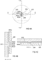
- Figs 4A-4C and Figs 5A-5C illustrate embodiments of a connecting interface 404a, 504a where the first microfluidic channel 102 is provided with a header 401 in the connecting region.
- the header 401 is used to branch the first microfluidic channel 102 into a plurality of sub-channels 402a-d.
- the sub-channels 402a-d are here arranged in parallel.
- the header 401 serves to distribute the flow in the first microfluidic channel 102 to the sub-channels 402a-d, or vice versa depending on the flow direction.
- the use of the header 401 reduces the flow resistance at the connecting interface.
- the connecting interface 404a includes a plurality of slits 108 which are arranged in parallel. Each of the slits extends across each one of the plurality of sub-channels 402a-d. As a second microfluidic channel 202 is coupled into the connecting interface 404a, fluid from the second microfluidic channel 202 is thereby allowed to flow into each of the plurality of sub-channels 402a-d.
- the plurality of sub-channels reduces the flow resistance of the connecting interface and provides redundancy to improve reliability in the fluidic connection.
- the plurality of slits 108 are shown to be perpendicular to the direction of flow in the first microfluidic channel 102, it is to be understood that the plurality of slits 108 may be arranged at any angle to the direction of flow.
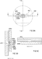
- the connecting interface 504a includes a plurality of slits 108 which are arranged in parallel. However, the connecting interface 504a differs from the connecting interface 404a of Figs 4A-4C in that the plurality of slits 108 are arranged in line with the sub-channels.
- Each sub-channel 402a-d is hence associated with a respective slit 108a-d which is arranged in line with the sub-channel 402a-d.
- Each slit 108a-d hence extends in a direction parallel to a longitudinal direction of a respective sub-channel 402a-d.
- Figs 6A-6C , Fig. 7 and Fig. 8 illustrate embodiments where this is not the case.
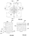
- Figs 6A-6C illustrate a connecting interface 604. Similar to the connecting interfaces described above, the connecting interface 604 comprises a first microfluidic channel 102 and a plurality of slits 108.
- the first microfluidic channel 102 forms a chamber at the connecting region 110 as described above.
- the illustrated chamber has a circular shape as seen in a plane parallel to the outer surface 120 of the second substrate 116.
- an array of micropillars 601 may be arranged in the connecting region 110, i.e., in the chamber.
- the plurality of slits 108 are arranged in a radial pattern.
- the plurality of slits 108 extends outside the connecting region 110 along radial directions in relation to a center C of the connection region 110. Each slits 108 hence extends beyond the circular shape of the connection region 110 along a radial direction. In Figs 6A-6C each slit is elongated in a direction parallel to the outer surface 120 and hence has a straight shape.
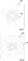
- Figs 7 and 8 illustrate connecting interfaces 704 and 804, respectively.
- the connecting interfaces 704 and 804 differs from the connecting interface 604 of Figs 6A-6C in that the plurality of slits 108 are curved along the outer surface 120. It is to be understood that different curved shapes may have different advantages when it comes to making the connection interface less sensitive to misalignments, reducing the amount of fluid consumed by the slits, and reducing the flow resistance at the interface.
- Figs 7 and 8 illustrate two examples, although many variations are possible depending at the application at hand. It is further understood that slits having a curved shape are generally possible, not only for slits being arranged in a radial pattern. In fact, the slits shown in any of the examples above could be arranged to have a curved instead of a straight shape.
Landscapes
- Chemical & Material Sciences (AREA)
- Health & Medical Sciences (AREA)
- Dispersion Chemistry (AREA)
- Analytical Chemistry (AREA)
- General Health & Medical Sciences (AREA)
- Hematology (AREA)
- Clinical Laboratory Science (AREA)
- Chemical Kinetics & Catalysis (AREA)
- Micromachines (AREA)
- Physical Or Chemical Processes And Apparatus (AREA)
Claims (20)
- Verbindungsschnittstelle (104, 204a, 204b, 304a, 404a, 504a, 604, 704, 804) für kapillargetriebene fluidtechnisch verbindende Mikrofluidkanäle (102, 202), wobei die Verbindungsschnittstelle ein oder mehrere Substrate (114, 116) umfasst, die gemeinsam Folgendes definieren:einen ersten Mikrofluidkanal (102), der einen Verbindungsbereich (110) enthält, um den ersten Mikrofluidkanal (102) mit einem zweiten Mikrofluidkanal (202) fluidtechnisch zu verbinden, undmindestens einen Schlitz (108) in einer Außenfläche (120) eines des einen oder der mehreren Substrate (114, 116), wobei der mindestens eine Schlitz (108) eine langgestreckte Form und eine Längsrichtung parallel zur Außenfläche (120) aufweist, der mindestens eine Schlitz (108) einen Fluiddurchlass von der Außenfläche (120) zum Verbindungsbereich (110) des ersten Mikrofluidkanals (102) schafft und der erste Mikrofluidkanal (102) eine Längsrichtung parallel zur Außenfläche (120) aufweist,dadurch gekennzeichnet, dassder mindestens eine Schlitz (108) mindestens eine Ausdehnung aufweist, die in einer Richtung (d1, d2) parallel zur Außenfläche (120) über den Verbindungsbereich (110) hinaus verläuft, wobeider Verbindungsbereich (110) ein Schnittbereich zwischen dem ersten Mikrofluidkanal (102) und dem mindestens einen Schlitz (108) ist.
- Verbindungsschnittstelle nach Anspruch 1, wobei das eine oder die mehreren Substrate Folgendes umfassen:ein erstes Substrat (114), das den ersten Mikrofluidkanal (102) enthält, wobei der Verbindungsbereich (110) des ersten Mikrofluidkanals (102) in einer ersten Oberfläche (118) des ersten Substrats (114) angeordnet ist, undein zweites Substrat (116), das an der ersten Oberfläche (118) angeordnet ist, wobei der mindestens eine Schlitz (108) in einer Außenfläche (120) des zweiten Substrats (116) angeordnet ist, um einen Fluiddurchlass zwischen der Außenfläche (120) des zweiten Substrats (116) und dem Verbindungsbereich (110) des ersten Mikrofluidkanals (102) im ersten Substrat (114) zu schaffen.
- Verbindungsschnittstelle nach Anspruch 1, wobei der erste Mikrofluidkanal (102) und der mindestens eine Schlitz (108) im selben Substrat (116) definiert sind.
- Verbindungsschnittstelle nach einem der vorhergehenden Ansprüche, wobei der mindestens eine Schlitz (108) aus mehreren Schlitzen besteht.
- Verbindungsschnittstelle nach Anspruch 4, wobei die mehreren Schlitze (108) parallel angeordnet sind.
- Verbindungsschnittstelle nach einem der vorhergehenden Ansprüche, wobei eine Längsrichtung des mindestens einen Schlitzes (108) parallel zu einer Längsrichtung des ersten Mikrofluidkanals (102) im Verbindungsbereich (110) ist.
- Verbindungsschnittstelle nach einem der Ansprüche 1-5, wobei eine Längsrichtung des mindestens einen Schlitzes (108) einen Winkel in Bezug auf eine Längsrichtung des ersten Mikrofluidkanals (102) im Verbindungsbereich (110) bildet.
- Verbindungsschnittstelle nach einem der Ansprüche 1-5, wobei der erste Mikrofluidkanal (102) in mehrere Unterkanäle (402a, 402b, 402c, 402d) verzweigt ist und der Verbindungsbereich (110) durch einen Schnittbereich zwischen dem mindestens einen Schlitz (108) und den mehreren Unterkanälen (402a, 402b, 402c, 402d) definiert ist.
- Verbindungsschnittstelle nach Anspruch 8, wobei mehrere Schlitze (108) in der Außenfläche (120) vorhanden sind und jeder Unterkanal (402a, 402b, 402c, 402d) der mehreren Unterkanäle einem jeweiligen Schlitz (108a, 108b, 108c, 108d), der einen Fluiddurchlass zwischen der Außenfläche (120) und dem Unterkanal (402a, 402b, 402c, 402d) schafft und der in einer Richtung parallel zu einer Längsrichtung des Unterkanals verläuft, zugeordnet ist.
- Verbindungsschnittstelle nach Anspruch 8, wobei mehrere Schlitze (108) in der Außenfläche (120) vorhanden sind und jeder Schlitz (108) durch jeden der mehreren Unterkanäle (402a, 402b, 402c, 402d) verläuft.
- Verbindungsschnittstelle nach Anspruch 4, wobei die mehreren Schlitze (108) in radialen Richtungen in Bezug auf ein Zentrum (C) des Verbindungsbereichs (110) über den Verbindungsbereich (110) hinaus verlaufen.
- Verbindungsschnittstelle nach Anspruch 11, wobei der Verbindungsbereich (110) eine Kreisform in einem Querschnitt parallel zur Außenfläche (120) besitzt und die mehreren Schlitze (108) jeweils in einer der Radialrichtungen über die Kreisform hinaus verlaufen.
- Verbindungsschnittstelle nach einem der vorhergehenden Ansprüche, wobei der erste Mikrofluidkanal (102) ein geschlossenes Ende (112) enthält und der Verbindungsbereich (110) beim geschlossenen Ende (112) angeordnet ist.
- Verbindungsschnittstelle nach einem der vorhergehenden Ansprüche, wobei ein Abschnitt des ersten Mikrofluidkanals (102) im Verbindungsbereich (110) eine erste Breite besitzt und ein weiterer Abschnitt des ersten Mikrofluidkanals (102) außerhalb des Verbindungsbereichs (110) eine zweite kleinere Breite besitzt, derart, dass der erste Mikrofluidkanal (102) eine Kammer am Verbindungsbereich (110) bildet.
- Verbindungsschnittstelle nach einem der vorhergehenden Ansprüche, wobei der Verbindungsbereich (110) eine Mikrosäulenanordnung (601) enthält.
- Verbindungsschnittstelle nach einem der vorhergehenden Ansprüche, wobei eine Längsrichtung des mindestens einen Schlitzes (108) parallel zur Außenfläche (120) ist.
- Verbindungsschnittstelle nach einem der vorhergehenden Ansprüche, wobei der mindestens eine Schlitz (108) entlang der Außenfläche (120) gekrümmt ist.
- Mikrofluidverbindung, um Mikrofluidkanäle (102, 202) fluidtechnisch zu verbinden, wobei die Mikrofluidverbindung Folgendes umfasst:die Verbindungsschnittstelle (104, 204a, 204b, 304a, 404a, 504a, 604, 704, 804) nach einem der Ansprüche 1-17 undein weiteres Substrat (117), das einen zweiten Mikrofluidkanal (202) enthält, der bei der Außenfläche (120) derart angeordnet ist, dass er den mindestens einen Schlitz (108) kreuzt, um den zweiten Mikrofluidkanal (202) mit dem ersten Mikrofluidkanal (102) fluidtechnisch zu verbinden.
- Mikrofluidverbindung nach Anspruch 18, die ferner Folgendes umfasst:eine Klebeschicht (219), die zwischen der Außenfläche (120) und dem weiteren Substrat (117) angeordnet ist, wobeidie Klebeschicht (219) eine Öffnung (121) besitzt, die mit mindestens einem Abschnitt des mindestens einen Schlitzes (108) in der Außenfläche (120) überlappt, um den ersten Mikrofluidkanal (102) mit dem zweite Mikrofluidkanal (202) fluidtechnisch zu verbinden.
- Diagnosevorrichtung, die die Verbindungsschnittstelle (104, 204a, 204b, 304a, 404a, 504a, 604, 704, 804) nach einem der Ansprüche 1-17 oder die Mikrofluidverbindung nach den Ansprüchen 18-19 umfasst.
Applications Claiming Priority (1)
| Application Number | Priority Date | Filing Date | Title |
|---|---|---|---|
| EP18173872 | 2018-05-23 |
Publications (2)
| Publication Number | Publication Date |
|---|---|
| EP3572151A1 EP3572151A1 (de) | 2019-11-27 |
| EP3572151B1 true EP3572151B1 (de) | 2021-07-07 |
Family
ID=62244330
Family Applications (1)
| Application Number | Title | Priority Date | Filing Date |
|---|---|---|---|
| EP19175985.1A Active EP3572151B1 (de) | 2018-05-23 | 2019-05-22 | Mikrofluidische verbindung und verbindungsschnittstelle zum fluidischen verbinden von mikrofluidischen kanälen |
Country Status (2)
| Country | Link |
|---|---|
| US (1) | US11583852B2 (de) |
| EP (1) | EP3572151B1 (de) |
Families Citing this family (1)
| Publication number | Priority date | Publication date | Assignee | Title |
|---|---|---|---|---|
| JP2023510312A (ja) * | 2020-01-14 | 2023-03-13 | ミダイアグノスティクス・エヌブイ | 毛細管駆動流体接続用のマイクロ流体装置 |
Family Cites Families (5)
| Publication number | Priority date | Publication date | Assignee | Title |
|---|---|---|---|---|
| US6106685A (en) | 1997-05-13 | 2000-08-22 | Sarnoff Corporation | Electrode combinations for pumping fluids |
| US20080257754A1 (en) * | 2003-06-27 | 2008-10-23 | Pugia Michael J | Method and apparatus for entry of specimens into a microfluidic device |
| US20070048189A1 (en) * | 2005-08-26 | 2007-03-01 | Applera Corporation | Fluid processing device, system, kit, and method |
| US20080233011A1 (en) | 2007-03-23 | 2008-09-25 | 3M Innovative Properties Company | Microfluidic devices |
| EP3230748B1 (de) * | 2015-01-30 | 2020-03-18 | Hewlett-Packard Development Company, L.P. | Diagnostischer chip |
-
2019
- 2019-05-22 EP EP19175985.1A patent/EP3572151B1/de active Active
- 2019-05-22 US US16/419,316 patent/US11583852B2/en active Active
Non-Patent Citations (1)
| Title |
|---|
| None * |
Also Published As
| Publication number | Publication date |
|---|---|
| US20190358631A1 (en) | 2019-11-28 |
| EP3572151A1 (de) | 2019-11-27 |
| US11583852B2 (en) | 2023-02-21 |
Similar Documents
| Publication | Publication Date | Title |
|---|---|---|
| KR100540143B1 (ko) | 미소 유체 제어소자 및 미소 유체의 제어 방법 | |
| US8747777B2 (en) | Microfluidic apparatus including microfluidic device | |
| US7238324B2 (en) | Microfluidic device for the controlled movement of fluid | |
| US9261436B2 (en) | Fluid treatment device and method for treating fluid | |
| US6901963B2 (en) | Micro fluidic device for controlling flow time of micro fluid | |
| CN102862944B (zh) | 微流体装置,微流体系统和用于输送流体的方法 | |
| JP2004225912A (ja) | マイクロ流体スイッチ | |
| US20060275184A1 (en) | Liquid/liquid interface reaction equipment | |
| EP3572151B1 (de) | Mikrofluidische verbindung und verbindungsschnittstelle zum fluidischen verbinden von mikrofluidischen kanälen | |
| WO2019107231A1 (ja) | マイクロ流体チップ | |
| KR100758274B1 (ko) | 챔버 내에서의 다중 미세 유체의 흐름을 균일화하기 위한미세 유체 소자, 및 그를 이용한 미세 유로 망 | |
| JP4488704B2 (ja) | マイクロ流体装置及びマイクロ流体デバイスの集積方法 | |
| EP3677337A1 (de) | Partikelabscheidungsvorrichtung und partikelabscheidungseinrichtung damit | |
| KR102561447B1 (ko) | 유체다이오드 및 유체이송장치 | |
| US11590497B2 (en) | Passive fluidic connection between two hydrophilic substrates | |
| US11364496B2 (en) | Coplanar fluidic interconnect | |
| KR20180114140A (ko) | 유로 장치 및 액적 형성 방법 | |
| EP3781405B1 (de) | Träger mit flüssigkeitsausstossdüsen | |
| KR100591244B1 (ko) | 유체주입구의 압력을 제어할 수 있는 미세 유체 소자 및이를 구비하는 미세 유로망 | |
| JP6936057B2 (ja) | マイクロ流体デバイス及び反応システム | |
| US20210031192A1 (en) | Microfluidic devices | |
| US11235328B2 (en) | Coplanar microfluidic manipulation | |
| JP2020000227A (ja) | 分析用具及び分析装置 |
Legal Events
| Date | Code | Title | Description |
|---|---|---|---|
| PUAI | Public reference made under article 153(3) epc to a published international application that has entered the european phase |
Free format text: ORIGINAL CODE: 0009012 |
|
| STAA | Information on the status of an ep patent application or granted ep patent |
Free format text: STATUS: THE APPLICATION HAS BEEN PUBLISHED |
|
| AK | Designated contracting states |
Kind code of ref document: A1 Designated state(s): AL AT BE BG CH CY CZ DE DK EE ES FI FR GB GR HR HU IE IS IT LI LT LU LV MC MK MT NL NO PL PT RO RS SE SI SK SM TR |
|
| AX | Request for extension of the european patent |
Extension state: BA ME |
|
| STAA | Information on the status of an ep patent application or granted ep patent |
Free format text: STATUS: REQUEST FOR EXAMINATION WAS MADE |
|
| STAA | Information on the status of an ep patent application or granted ep patent |
Free format text: STATUS: EXAMINATION IS IN PROGRESS |
|
| 17P | Request for examination filed |
Effective date: 20200527 |
|
| RBV | Designated contracting states (corrected) |
Designated state(s): AL AT BE BG CH CY CZ DE DK EE ES FI FR GB GR HR HU IE IS IT LI LT LU LV MC MK MT NL NO PL PT RO RS SE SI SK SM TR |
|
| 17Q | First examination report despatched |
Effective date: 20200612 |
|
| GRAP | Despatch of communication of intention to grant a patent |
Free format text: ORIGINAL CODE: EPIDOSNIGR1 |
|
| STAA | Information on the status of an ep patent application or granted ep patent |
Free format text: STATUS: GRANT OF PATENT IS INTENDED |
|
| INTG | Intention to grant announced |
Effective date: 20210225 |
|
| GRAS | Grant fee paid |
Free format text: ORIGINAL CODE: EPIDOSNIGR3 |
|
| GRAA | (expected) grant |
Free format text: ORIGINAL CODE: 0009210 |
|
| STAA | Information on the status of an ep patent application or granted ep patent |
Free format text: STATUS: THE PATENT HAS BEEN GRANTED |
|
| AK | Designated contracting states |
Kind code of ref document: B1 Designated state(s): AL AT BE BG CH CY CZ DE DK EE ES FI FR GB GR HR HU IE IS IT LI LT LU LV MC MK MT NL NO PL PT RO RS SE SI SK SM TR |
|
| REG | Reference to a national code |
Ref country code: GB Ref legal event code: FG4D |
|
| REG | Reference to a national code |
Ref country code: AT Ref legal event code: REF Ref document number: 1408032 Country of ref document: AT Kind code of ref document: T Effective date: 20210715 |
|
| REG | Reference to a national code |
Ref country code: DE Ref legal event code: R096 Ref document number: 602019005867 Country of ref document: DE |
|
| REG | Reference to a national code |
Ref country code: IE Ref legal event code: FG4D |
|
| REG | Reference to a national code |
Ref country code: LT Ref legal event code: MG9D |
|
| REG | Reference to a national code |
Ref country code: NL Ref legal event code: MP Effective date: 20210707 |
|
| REG | Reference to a national code |
Ref country code: AT Ref legal event code: MK05 Ref document number: 1408032 Country of ref document: AT Kind code of ref document: T Effective date: 20210707 |
|
| PG25 | Lapsed in a contracting state [announced via postgrant information from national office to epo] |
Ref country code: HR Free format text: LAPSE BECAUSE OF FAILURE TO SUBMIT A TRANSLATION OF THE DESCRIPTION OR TO PAY THE FEE WITHIN THE PRESCRIBED TIME-LIMIT Effective date: 20210707 Ref country code: PT Free format text: LAPSE BECAUSE OF FAILURE TO SUBMIT A TRANSLATION OF THE DESCRIPTION OR TO PAY THE FEE WITHIN THE PRESCRIBED TIME-LIMIT Effective date: 20211108 Ref country code: NL Free format text: LAPSE BECAUSE OF FAILURE TO SUBMIT A TRANSLATION OF THE DESCRIPTION OR TO PAY THE FEE WITHIN THE PRESCRIBED TIME-LIMIT Effective date: 20210707 Ref country code: NO Free format text: LAPSE BECAUSE OF FAILURE TO SUBMIT A TRANSLATION OF THE DESCRIPTION OR TO PAY THE FEE WITHIN THE PRESCRIBED TIME-LIMIT Effective date: 20211007 Ref country code: LT Free format text: LAPSE BECAUSE OF FAILURE TO SUBMIT A TRANSLATION OF THE DESCRIPTION OR TO PAY THE FEE WITHIN THE PRESCRIBED TIME-LIMIT Effective date: 20210707 Ref country code: BG Free format text: LAPSE BECAUSE OF FAILURE TO SUBMIT A TRANSLATION OF THE DESCRIPTION OR TO PAY THE FEE WITHIN THE PRESCRIBED TIME-LIMIT Effective date: 20211007 Ref country code: AT Free format text: LAPSE BECAUSE OF FAILURE TO SUBMIT A TRANSLATION OF THE DESCRIPTION OR TO PAY THE FEE WITHIN THE PRESCRIBED TIME-LIMIT Effective date: 20210707 Ref country code: RS Free format text: LAPSE BECAUSE OF FAILURE TO SUBMIT A TRANSLATION OF THE DESCRIPTION OR TO PAY THE FEE WITHIN THE PRESCRIBED TIME-LIMIT Effective date: 20210707 Ref country code: SE Free format text: LAPSE BECAUSE OF FAILURE TO SUBMIT A TRANSLATION OF THE DESCRIPTION OR TO PAY THE FEE WITHIN THE PRESCRIBED TIME-LIMIT Effective date: 20210707 Ref country code: FI Free format text: LAPSE BECAUSE OF FAILURE TO SUBMIT A TRANSLATION OF THE DESCRIPTION OR TO PAY THE FEE WITHIN THE PRESCRIBED TIME-LIMIT Effective date: 20210707 Ref country code: ES Free format text: LAPSE BECAUSE OF FAILURE TO SUBMIT A TRANSLATION OF THE DESCRIPTION OR TO PAY THE FEE WITHIN THE PRESCRIBED TIME-LIMIT Effective date: 20210707 |
|
| PG25 | Lapsed in a contracting state [announced via postgrant information from national office to epo] |
Ref country code: PL Free format text: LAPSE BECAUSE OF FAILURE TO SUBMIT A TRANSLATION OF THE DESCRIPTION OR TO PAY THE FEE WITHIN THE PRESCRIBED TIME-LIMIT Effective date: 20210707 Ref country code: LV Free format text: LAPSE BECAUSE OF FAILURE TO SUBMIT A TRANSLATION OF THE DESCRIPTION OR TO PAY THE FEE WITHIN THE PRESCRIBED TIME-LIMIT Effective date: 20210707 Ref country code: GR Free format text: LAPSE BECAUSE OF FAILURE TO SUBMIT A TRANSLATION OF THE DESCRIPTION OR TO PAY THE FEE WITHIN THE PRESCRIBED TIME-LIMIT Effective date: 20211008 |
|
| REG | Reference to a national code |
Ref country code: DE Ref legal event code: R097 Ref document number: 602019005867 Country of ref document: DE |
|
| PG25 | Lapsed in a contracting state [announced via postgrant information from national office to epo] |
Ref country code: DK Free format text: LAPSE BECAUSE OF FAILURE TO SUBMIT A TRANSLATION OF THE DESCRIPTION OR TO PAY THE FEE WITHIN THE PRESCRIBED TIME-LIMIT Effective date: 20210707 |
|
| PLBE | No opposition filed within time limit |
Free format text: ORIGINAL CODE: 0009261 |
|
| STAA | Information on the status of an ep patent application or granted ep patent |
Free format text: STATUS: NO OPPOSITION FILED WITHIN TIME LIMIT |
|
| PG25 | Lapsed in a contracting state [announced via postgrant information from national office to epo] |
Ref country code: SM Free format text: LAPSE BECAUSE OF FAILURE TO SUBMIT A TRANSLATION OF THE DESCRIPTION OR TO PAY THE FEE WITHIN THE PRESCRIBED TIME-LIMIT Effective date: 20210707 Ref country code: SK Free format text: LAPSE BECAUSE OF FAILURE TO SUBMIT A TRANSLATION OF THE DESCRIPTION OR TO PAY THE FEE WITHIN THE PRESCRIBED TIME-LIMIT Effective date: 20210707 Ref country code: RO Free format text: LAPSE BECAUSE OF FAILURE TO SUBMIT A TRANSLATION OF THE DESCRIPTION OR TO PAY THE FEE WITHIN THE PRESCRIBED TIME-LIMIT Effective date: 20210707 Ref country code: EE Free format text: LAPSE BECAUSE OF FAILURE TO SUBMIT A TRANSLATION OF THE DESCRIPTION OR TO PAY THE FEE WITHIN THE PRESCRIBED TIME-LIMIT Effective date: 20210707 Ref country code: CZ Free format text: LAPSE BECAUSE OF FAILURE TO SUBMIT A TRANSLATION OF THE DESCRIPTION OR TO PAY THE FEE WITHIN THE PRESCRIBED TIME-LIMIT Effective date: 20210707 Ref country code: AL Free format text: LAPSE BECAUSE OF FAILURE TO SUBMIT A TRANSLATION OF THE DESCRIPTION OR TO PAY THE FEE WITHIN THE PRESCRIBED TIME-LIMIT Effective date: 20210707 |
|
| 26N | No opposition filed |
Effective date: 20220408 |
|
| PG25 | Lapsed in a contracting state [announced via postgrant information from national office to epo] |
Ref country code: IT Free format text: LAPSE BECAUSE OF FAILURE TO SUBMIT A TRANSLATION OF THE DESCRIPTION OR TO PAY THE FEE WITHIN THE PRESCRIBED TIME-LIMIT Effective date: 20210707 |
|
| REG | Reference to a national code |
Ref country code: CH Ref legal event code: PL |
|
| REG | Reference to a national code |
Ref country code: BE Ref legal event code: MM Effective date: 20220531 |
|
| PG25 | Lapsed in a contracting state [announced via postgrant information from national office to epo] |
Ref country code: MC Free format text: LAPSE BECAUSE OF FAILURE TO SUBMIT A TRANSLATION OF THE DESCRIPTION OR TO PAY THE FEE WITHIN THE PRESCRIBED TIME-LIMIT Effective date: 20210707 Ref country code: LU Free format text: LAPSE BECAUSE OF NON-PAYMENT OF DUE FEES Effective date: 20220522 Ref country code: LI Free format text: LAPSE BECAUSE OF NON-PAYMENT OF DUE FEES Effective date: 20220531 Ref country code: CH Free format text: LAPSE BECAUSE OF NON-PAYMENT OF DUE FEES Effective date: 20220531 |
|
| PG25 | Lapsed in a contracting state [announced via postgrant information from national office to epo] |
Ref country code: IE Free format text: LAPSE BECAUSE OF NON-PAYMENT OF DUE FEES Effective date: 20220522 |
|
| PG25 | Lapsed in a contracting state [announced via postgrant information from national office to epo] |
Ref country code: BE Free format text: LAPSE BECAUSE OF NON-PAYMENT OF DUE FEES Effective date: 20220531 |
|
| P01 | Opt-out of the competence of the unified patent court (upc) registered |
Effective date: 20230508 |
|
| REG | Reference to a national code |
Ref country code: DE Ref legal event code: R081 Ref document number: 602019005867 Country of ref document: DE Owner name: MIDIAGNOSTICS NV, BE Free format text: FORMER OWNER: MIDIAGNOSTICS NV, LEUVEN, BE |
|
| PG25 | Lapsed in a contracting state [announced via postgrant information from national office to epo] |
Ref country code: HU Free format text: LAPSE BECAUSE OF FAILURE TO SUBMIT A TRANSLATION OF THE DESCRIPTION OR TO PAY THE FEE WITHIN THE PRESCRIBED TIME-LIMIT; INVALID AB INITIO Effective date: 20190522 |
|
| PG25 | Lapsed in a contracting state [announced via postgrant information from national office to epo] |
Ref country code: MK Free format text: LAPSE BECAUSE OF FAILURE TO SUBMIT A TRANSLATION OF THE DESCRIPTION OR TO PAY THE FEE WITHIN THE PRESCRIBED TIME-LIMIT Effective date: 20210707 Ref country code: CY Free format text: LAPSE BECAUSE OF FAILURE TO SUBMIT A TRANSLATION OF THE DESCRIPTION OR TO PAY THE FEE WITHIN THE PRESCRIBED TIME-LIMIT Effective date: 20210707 |
|
| PG25 | Lapsed in a contracting state [announced via postgrant information from national office to epo] |
Ref country code: TR Free format text: LAPSE BECAUSE OF FAILURE TO SUBMIT A TRANSLATION OF THE DESCRIPTION OR TO PAY THE FEE WITHIN THE PRESCRIBED TIME-LIMIT Effective date: 20210707 |
|
| PG25 | Lapsed in a contracting state [announced via postgrant information from national office to epo] |
Ref country code: MT Free format text: LAPSE BECAUSE OF FAILURE TO SUBMIT A TRANSLATION OF THE DESCRIPTION OR TO PAY THE FEE WITHIN THE PRESCRIBED TIME-LIMIT Effective date: 20210707 |
|
| PGFP | Annual fee paid to national office [announced via postgrant information from national office to epo] |
Ref country code: DE Payment date: 20250416 Year of fee payment: 7 |
|
| PGFP | Annual fee paid to national office [announced via postgrant information from national office to epo] |
Ref country code: GB Payment date: 20250414 Year of fee payment: 7 |
|
| PGFP | Annual fee paid to national office [announced via postgrant information from national office to epo] |
Ref country code: FR Payment date: 20250414 Year of fee payment: 7 |