EP3572022B1 - Elektrochirurgische medizinische vorrichtung mit leistungsmodulation - Google Patents
Elektrochirurgische medizinische vorrichtung mit leistungsmodulation Download PDFInfo
- Publication number
- EP3572022B1 EP3572022B1 EP19173012.6A EP19173012A EP3572022B1 EP 3572022 B1 EP3572022 B1 EP 3572022B1 EP 19173012 A EP19173012 A EP 19173012A EP 3572022 B1 EP3572022 B1 EP 3572022B1
- Authority
- EP
- European Patent Office
- Prior art keywords
- power
- medical treatment
- treatment system
- pulse width
- block
- Prior art date
- Legal status (The legal status is an assumption and is not a legal conclusion. Google has not performed a legal analysis and makes no representation as to the accuracy of the status listed.)
- Active
Links
Images




Classifications
-
- A—HUMAN NECESSITIES
- A61—MEDICAL OR VETERINARY SCIENCE; HYGIENE
- A61B—DIAGNOSIS; SURGERY; IDENTIFICATION
- A61B18/00—Surgical instruments, devices or methods for transferring non-mechanical forms of energy to or from the body
- A61B18/04—Surgical instruments, devices or methods for transferring non-mechanical forms of energy to or from the body by heating
- A61B18/12—Surgical instruments, devices or methods for transferring non-mechanical forms of energy to or from the body by heating by passing a current through the tissue to be heated, e.g. high-frequency current
-
- A—HUMAN NECESSITIES
- A61—MEDICAL OR VETERINARY SCIENCE; HYGIENE
- A61B—DIAGNOSIS; SURGERY; IDENTIFICATION
- A61B18/00—Surgical instruments, devices or methods for transferring non-mechanical forms of energy to or from the body
- A61B18/04—Surgical instruments, devices or methods for transferring non-mechanical forms of energy to or from the body by heating
-
- A—HUMAN NECESSITIES
- A61—MEDICAL OR VETERINARY SCIENCE; HYGIENE
- A61B—DIAGNOSIS; SURGERY; IDENTIFICATION
- A61B18/00—Surgical instruments, devices or methods for transferring non-mechanical forms of energy to or from the body
- A61B18/04—Surgical instruments, devices or methods for transferring non-mechanical forms of energy to or from the body by heating
- A61B18/08—Surgical instruments, devices or methods for transferring non-mechanical forms of energy to or from the body by heating by means of electrically-heated probes
- A61B18/10—Power sources therefor
-
- A—HUMAN NECESSITIES
- A61—MEDICAL OR VETERINARY SCIENCE; HYGIENE
- A61B—DIAGNOSIS; SURGERY; IDENTIFICATION
- A61B18/00—Surgical instruments, devices or methods for transferring non-mechanical forms of energy to or from the body
- A61B18/04—Surgical instruments, devices or methods for transferring non-mechanical forms of energy to or from the body by heating
- A61B18/12—Surgical instruments, devices or methods for transferring non-mechanical forms of energy to or from the body by heating by passing a current through the tissue to be heated, e.g. high-frequency current
- A61B18/1206—Generators therefor
-
- A—HUMAN NECESSITIES
- A61—MEDICAL OR VETERINARY SCIENCE; HYGIENE
- A61B—DIAGNOSIS; SURGERY; IDENTIFICATION
- A61B90/00—Instruments, implements or accessories specially adapted for surgery or diagnosis and not covered by any of the groups A61B1/00 - A61B50/00, e.g. for luxation treatment or for protecting wound edges
- A61B90/08—Accessories or related features not otherwise provided for
-
- A—HUMAN NECESSITIES
- A61—MEDICAL OR VETERINARY SCIENCE; HYGIENE
- A61B—DIAGNOSIS; SURGERY; IDENTIFICATION
- A61B18/00—Surgical instruments, devices or methods for transferring non-mechanical forms of energy to or from the body
- A61B18/04—Surgical instruments, devices or methods for transferring non-mechanical forms of energy to or from the body by heating
- A61B18/08—Surgical instruments, devices or methods for transferring non-mechanical forms of energy to or from the body by heating by means of electrically-heated probes
- A61B18/082—Probes or electrodes therefor
-
- A—HUMAN NECESSITIES
- A61—MEDICAL OR VETERINARY SCIENCE; HYGIENE
- A61B—DIAGNOSIS; SURGERY; IDENTIFICATION
- A61B18/00—Surgical instruments, devices or methods for transferring non-mechanical forms of energy to or from the body
- A61B18/04—Surgical instruments, devices or methods for transferring non-mechanical forms of energy to or from the body by heating
- A61B18/12—Surgical instruments, devices or methods for transferring non-mechanical forms of energy to or from the body by heating by passing a current through the tissue to be heated, e.g. high-frequency current
- A61B18/14—Probes or electrodes therefor
- A61B18/1492—Probes or electrodes therefor having a flexible, catheter-like structure, e.g. for heart ablation
-
- A—HUMAN NECESSITIES
- A61—MEDICAL OR VETERINARY SCIENCE; HYGIENE
- A61B—DIAGNOSIS; SURGERY; IDENTIFICATION
- A61B17/00—Surgical instruments, devices or methods
- A61B2017/00017—Electrical control of surgical instruments
- A61B2017/00137—Details of operation mode
- A61B2017/00154—Details of operation mode pulsed
-
- A—HUMAN NECESSITIES
- A61—MEDICAL OR VETERINARY SCIENCE; HYGIENE
- A61B—DIAGNOSIS; SURGERY; IDENTIFICATION
- A61B18/00—Surgical instruments, devices or methods for transferring non-mechanical forms of energy to or from the body
- A61B2018/00053—Mechanical features of the instrument of device
- A61B2018/00107—Coatings on the energy applicator
- A61B2018/00136—Coatings on the energy applicator with polymer
-
- A—HUMAN NECESSITIES
- A61—MEDICAL OR VETERINARY SCIENCE; HYGIENE
- A61B—DIAGNOSIS; SURGERY; IDENTIFICATION
- A61B18/00—Surgical instruments, devices or methods for transferring non-mechanical forms of energy to or from the body
- A61B2018/00315—Surgical instruments, devices or methods for transferring non-mechanical forms of energy to or from the body for treatment of particular body parts
- A61B2018/00345—Vascular system
- A61B2018/00404—Blood vessels other than those in or around the heart
-
- A—HUMAN NECESSITIES
- A61—MEDICAL OR VETERINARY SCIENCE; HYGIENE
- A61B—DIAGNOSIS; SURGERY; IDENTIFICATION
- A61B18/00—Surgical instruments, devices or methods for transferring non-mechanical forms of energy to or from the body
- A61B2018/00571—Surgical instruments, devices or methods for transferring non-mechanical forms of energy to or from the body for achieving a particular surgical effect
- A61B2018/0063—Sealing
-
- A—HUMAN NECESSITIES
- A61—MEDICAL OR VETERINARY SCIENCE; HYGIENE
- A61B—DIAGNOSIS; SURGERY; IDENTIFICATION
- A61B18/00—Surgical instruments, devices or methods for transferring non-mechanical forms of energy to or from the body
- A61B2018/00636—Sensing and controlling the application of energy
- A61B2018/00642—Sensing and controlling the application of energy with feedback, i.e. closed loop control
-
- A—HUMAN NECESSITIES
- A61—MEDICAL OR VETERINARY SCIENCE; HYGIENE
- A61B—DIAGNOSIS; SURGERY; IDENTIFICATION
- A61B18/00—Surgical instruments, devices or methods for transferring non-mechanical forms of energy to or from the body
- A61B2018/00636—Sensing and controlling the application of energy
- A61B2018/00696—Controlled or regulated parameters
- A61B2018/00726—Duty cycle
-
- A—HUMAN NECESSITIES
- A61—MEDICAL OR VETERINARY SCIENCE; HYGIENE
- A61B—DIAGNOSIS; SURGERY; IDENTIFICATION
- A61B18/00—Surgical instruments, devices or methods for transferring non-mechanical forms of energy to or from the body
- A61B2018/00636—Sensing and controlling the application of energy
- A61B2018/00773—Sensed parameters
- A61B2018/00791—Temperature
-
- A—HUMAN NECESSITIES
- A61—MEDICAL OR VETERINARY SCIENCE; HYGIENE
- A61B—DIAGNOSIS; SURGERY; IDENTIFICATION
- A61B18/00—Surgical instruments, devices or methods for transferring non-mechanical forms of energy to or from the body
- A61B18/04—Surgical instruments, devices or methods for transferring non-mechanical forms of energy to or from the body by heating
- A61B18/12—Surgical instruments, devices or methods for transferring non-mechanical forms of energy to or from the body by heating by passing a current through the tissue to be heated, e.g. high-frequency current
- A61B18/1206—Generators therefor
- A61B2018/1226—Generators therefor powered by a battery
Definitions
- Electrosurgical procedures use a treatment device to apply energy to a body part of a patient.
- techniques currently used for endovenous treatment for venous reflux disease, as well as other diseases in hollow anatomical structures (HAS) include electrosurgical procedures, including electrosurgical heating, radio frequency ablation (RFA), and laser ablation.
- electrosurgical heating for treating venous reflux disease may use radio frequency current to apply energy to create targeted tissue ablation to seal off damaged veins.
- Electrosurgical equipment typically includes a generator, such as an RF generator, and a catheter having a heating segment located at the distal end, which is inserted into the vein(s) during treatment. The heating segment may use RF energy driven by the RF generator to heat and seal the vein.
- Electrosurgical treatments are also used in other medical treatments, such as, for example, arthroscopic surgery, renal denervation, and cardiac surgery.
- AC power sources may not always be available or reliable in all locations.
- the invention relates to electrosurgical devices, for example for use in medical treatments capable of utilizing AC and/or DC power, while providing appropriate power to the treatment device to provide effective and safe treatment.
- the invention provides a medical treatment system according to claim 1. Preferred embodiments are defined in the dependent claims.
- An implementation of the disclosure features a direct current (DC) powered electrosurgical device including a catheter having a heating segment and modulation circuitry configured to modulate DC power provided to the heating segment.
- the electrosurgical device also includes at least one DC power source for providing the DC power to the first circuitry.
- the modulation is pulse width modulation (PWM).
- the modulation circuitry includes pulse width modulation (PWM) driver circuitry and optionally a switch.
- the at least one DC power source comprises two DC power sources.
- the first of the two DC power sources comprises an AC/DC power converter and a second of the two DC power sources may comprise a battery.
- Some embodiments further comprise a switch to switchably provide power from either the AC/DC converter or the battery to the PWM circuitry for provision to the heating segment.
- the AC/DC converter and the battery are coupled in parallel to the PWM circuitry.
- Some embodiments further comprise a DC/DC power converter coupled between the AC/DC power converter and the PWM circuitry.
- the heating segment comprises a resistive coil.
- the resistive coil is housed in a plastic cover.
- a frequency of the PWM is in a range of 1 kHz to 50 kHz, inclusive.
- modulating the DC power using PWM includes providing the DC power to a switch, and opening and closing the switch using a PWM driver signal.
- a frequency of the PWM is in the range of 1 kHz to 50 kHz, inclusive.
- providing DC power includes selectably providing DC power from an AC/DC power converter or from a battery.
- selection of provision of DC power from the AC/DC power converter or from the battery is based on availability of AC power to the AC/DC power converter.
- selection of DC power from the AC/DC power converter or from the battery may be performed during application of power to the heating element.
- the device further includes pulse width modulation (PWM) circuitry for modulating power provided to the resistive coil.
- PWM pulse width modulation
- an exemplary medical treatment 10 system includes a catheter shaft 12 having a distal end 13 and a proximal end 14.
- a heating segment 15 is operably attached towards or adjacent the distal end of the catheter shaft and a handle 16 is attached at the proximal end of the catheter shaft.
- a cable 17 electrically connects the heating segment 15 to a generator system 18.
- the cable 17 may be integral to the handle and removably connected to the generator system. Alternatively, the cable 17 may be removably connected to the handle.
- the heating segment 15 includes a heating element 20.
- the heating element 20 may in some embodiments be a resistive coil, which may be driven, for example, by RF energy.
- the relative resistance or impedance of the heating element 20 is designed to correlate to, or match, relative resistance or impedance of an output of the generator system 18 to which the heating element 20 is coupled.
- the resistance of the heating element 20 may be determined by a wire gage that relates to the catheter diameter, the energy required during treatment, and/or the power source specifications.
- the exemplary medical treatment system 10 may be used in various medical procedures, including endovenous treatments to treat venous reflux.
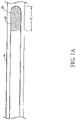
- a method (not part of the claimed invention) may comprise inserting the heating segment 15 into a distal-most section of a HAS 19 to be treated.
- the heating segment 15 is then aligned with a first treatment location T1 within the HAS.
- Power is then applied to the heating segment 15 for a desired length of time to treat the first treatment location T1.
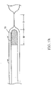
- a desired dwell time such as after the HAS has collapsed as shown in Figure 1B , the power supplied to the heating segment 15 may be reduced or shut off.
- the heating segment 15 may then be moved proximally until the distal end of the heating segment 15 is adjacent to the proximal end of the first treatment location T1, as shown in Figure 1B .
- the heating segment 15 may then be moved proximally until the distal end of the heating segment 15 is adjacent to the proximal end of the first treatment location T1, as shown in Figure 1B .
- power is again applied to the heating segment 15 for a desired length of time to treat the HAS at the second treatment location T2. This process is repeated until the treatment of the HAS is complete.
- T1 and T2 may overlap. While T1 and T2 are shown adjacent to one another in the same HAS, T1 and T2 may be in different locations, such as different HAS.
- the generator system includes at least one source of direct current (DC) power and modulation circuitry for modulating that power so that RF energy may be applied to the heating segment 15.
- the RF energy is generated by modulating DC power applied to the heating segment 15, by pulse width modulation (PWM) of the DC power applied to the heating segment 15.
- the modulation circuitry is pulse width modulation circuitry, which comprises pulse width modulation driver circuitry and optionally a switch.
- the source of DC power is coupled to the heating segment 15 by a switch, with the switch opened and closed for various portions of a periodic cycle in accordance with a pulse width modulation signal.
- the periodic cycle has a frequency in the radio frequency range, and in some embodiments the periodic cycle has a frequency range between 1 kHz and 50 kHz, inclusive.
- power is applied to the heating segment 15 when the switch is closed and not applied when the switch is in the open position, but in some embodiments the converse may be true.
- the switch may be provided, at least in part, by use of switch used for transfer of power, and in some embodiments the switch may include a power MOSFET or an insulated-gate bipolar transistor (IGBT).
- the generator system 18 in various embodiments incorporates a controller.
- the controller may be, in various embodiments, one or more processors, FPGAs, CPLDs, DSPs, or some combination thereof.
- the controller may perform various functions, including determining a duty cycle of the PWM based at least upon readings from a temperature sensor or sensors (e.g., a thermocouple, a thermistor, a resistance temperature device, an optical or infrared sensor, combinations of the same or the like) located in or adjacent to the heating segment 15. For example, the controller may heat the the heating segment 15 to a set temperature. In an alternative embodiment, the user selects a constant power output of the generator system 18. For example, the user may manually adjust the power output relative to the temperature display from a temperature sensor in the heating segment 15.
- a temperature sensor or sensors e.g., a thermocouple, a thermistor, a resistance temperature device, an optical or infrared sensor, combinations of the same or the like
- the generator system 18 includes multiple DC power sources, with different ones of the multiple DC power sources selectable, for example by the controller commanding operation of power switching circuitry, for use in provision of power to the heating element 20.
- the generator system 18 may include, or be provided power from, a battery as one DC power source and an AC/DC power converter coupled to an AC main (utility or generator power source), with the controller and power switching circuitry selecting use of one power source or the other based on, for example, availability of power from the AC derived power source.
- a battery as one DC power source
- AC/DC power converter coupled to an AC main (utility or generator power source
- an AC/DC power converter 21, coupled to a housing of the generator system 18 by an electrical coupling 23 and coupled to a source of AC power by an electrical coupling 25, may be considered part of the generator system 18.
- the power converter 21 may be integral to the generator system 18, such as being a part of the internal electronics.
- the controller and power switching circuitry may switch the source of power while power is generally being provided to the heating element 20, allowing for power source switching during operation of the medical treatment system 10.
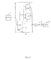
- FIG. 2 is a block diagram of an electrosurgical ablation device in accordance with aspects of the invention.
- an AC/DC power converter 211 receives AC power from a power source such as a utility or generator.
- the AC/DC power converter 211 converts the AC power to DC power.
- the AC power converter 211 may receive AC power in the range of 100-240 VA, and output power nominally at 24 V DC, with available current for example in the range of a few to several amps.
- the DC power is provided, or made available to, a generator unit 213, such as the generator system 18 described above.
- the generator unit 213 provides power to a heating segment (not shown) in FIG. 2 by way of providing power to a handle 221 and a catheter 223 coupled to the handle 221, with the catheter 223 including the heating segment, for example as discussed with respect to FIG. 1 , with reference to heating segment 15, handle 16 and catheter shaft 12.
- the provided power is pulse width modulated DC power.
- the generator unit 213 also receives signals from the catheter 223, for example signals indicative of temperature of the heating segment.
- the generator unit 213 may adjust a duty cycle of the PWM so as to adjust the temperature of the heating segment to a desired setting.
- the PWM has a periodic cycle in the RF range, and in some embodiments has a periodic cycle in the range of 1 kHz to 50 kHz, inclusive.
- the power block 215 receives DC power sourced from the AC/DC power converter 211.
- the power block 215 provides power to the handle 221 and the catheter 223 coupled to the handle 221.
- the catheter 223 includes a heating segment (not shown), for example as discussed with respect to FIG. 1 .
- the power block 215 therefore effectively provides power to the heating segment.
- the power block 215 modulates DC power to provide modulated RF power to the heating segment, for example using modulation circuitry of the power block 215.
- the modulation is pulse width modulation (PWM), and the modulation circuitry is pulse width modulation circuitry, for example including pulse width modulation driver circuitry and a switch.
- PWM pulse width modulation
- the modulation circuitry is pulse width modulation circuitry, for example including pulse width modulation driver circuitry and a switch.
- duty cycle of the PWM is determined by the control block 217, for example based on a desired temperature of the heating segment and signals from the catheter 223 indicative of temperature of the heating segment.
- the DC power which is modulated is at a different voltage than that provided by the AC/DC power converter 211, and in such embodiments one or more DC/DC power converters may be utilized to provide the DC power which is modulated.
- the AC/DC converter 211 provides DC power at 24 Volts, and the DC power which is modulated is about 15 Volts, for example 15 Volts to 16.8 Volts or 15.5 Volts.
- the power block 215 also provides power signals, and in some embodiments status signals, to a control block 217 and the monitor block 219.
- the power signals provided to the control block 217 and the monitor block 219 are in some embodiments appropriate for powering of circuitry within those blocks, and in other embodiments are appropriate for use by power control circuitry within those other blocks in powering circuitry, for example CMOS circuitry.
- the status signals may provide various signals relating to the status of power available to the power block 215.
- the power block 215 also includes a battery 225 and, in some such embodiments, a battery charger.
- the battery 225 may be in the form of a battery pack. In various embodiments the battery 225 may be physically separate from the power block 215, and in some embodiments may be external to a housing of the generator unit 213. In some embodiments the battery 225 may be for example a Lithium-ion battery pack.
- a Lithium-ion battery may be rechargeable, and in embodiments in which rechargeable batteries are used, the power block 215 may include battery charging circuitry.
- the battery charging circuitry may be provided power from the AC/DC power converter 211 in some embodiments, or a DC/DC power converter as previously discussed.
- the power block 215 may select, for example, using power switching circuitry of the power block 215, one or the other of DC power sourced from the AC/DC power converter 211 or DC power sourced from the battery 225 for modulation and provision to the heating segment of the catheter 223.
- the power block 215 may utilize DC power sourced from the AC/DC power converter 211 if such DC power is available, and utilize DC power sourced from the battery 225 if DC power is not available from the AC/DC power converter 211.
- power signals to the control block 217 and monitor block 219 also may be selected from either the AC/DC power converter 211 or the battery 225.
- status of availability of power from the AC/DC power converter 211 is provided to the control block 217, and the control block 217 provides command signals to the power block 215 instructing the power block 217 as to which source of power to utilize.
- control block 217 may receive signals indicative of temperature of the heating segment from the catheter 223 (by way of the handle 221) and signals indicative of availability of power sourced from the AC/DC power converter 211. Based on these signals, and in various embodiments other signals, the control block 217 may determine a duty cycle for pulse width modulation of the DC power to be provided to the catheter 223 and selection of a source of power to provide that DC power. Results of those determinations may be provided to the power block 215 in the form of command signals to the power block 215. In some embodiments the command signals include a signal indicating a duty cycle for PWM of the DC power. In some embodiments the control block 217 includes a programmable processor to make those determinations.
- the monitor block 219 also receives signals indicative of temperature about the heating segment from the catheter 223 (by way of the handle 221), as well as power and status signals from the power block 215.
- the monitor block 219 may include circuitry for performing various monitoring functions related to the status of the generator unit 213 and catheter 223.
- FIG. 3 is a block diagram of a power block 300 in accordance with aspects of the invention.
- the power block 300 of FIG. 3 is the power block 215 of FIG. 2 , and in some embodiments the power block 300 of FIG. 3 is similar to the power block 215 of FIG. 2 .
- the power block 300 of FIG. 3 is a portion of the power block 215 of FIG. 2 , and in some embodiments the power block 300 of FIG. 3 includes circuitry found in other blocks of the system of FIG. 2 .
- the power block 300 of FIG. 3 includes an AC/DC power converter 311.
- the AC/DC power converter 311 is external to the power block 300.
- the AC/DC power converter 311 is coupled to a source of AC power, for example a utility main or a generator, and the AC/DC power converter 311 converts AC power to DC power.
- the DC power supplied by the AC/DC power converter 311 is provided to a DC/DC power converter 313.
- the DC/DC power converter 313 converts the DC power supplied by the AC/DC power converter 311 to a different power level.
- the AC/DC power converter 311 may provide DC power at 24 Volts DC and the DC/DC power converter 313 may convert the power to 15.5 Volts DC.
- additional DC/DC power converters may be included between the AC/DC power converter 311 and the DC/DC power converter 313, for example to provide for electrical isolation features in event of voltage spikes from external sources.
- DC power from the DC/DC power converter 313 is provided to a pulse width modulator 323, for provision of pulse width modulated power to a heating segment of a catheter.
- the pulse width modulator 323, which in some embodiments comprises a switch, modulates the DC power to provide modulated DC power for use by a heating segment of a catheter, for example heating segment 15 of FIG. 1 .
- the pulse width modulator 323 modulates the DC power in accordance with signals from a PWM driver 325, and in some embodiments the PWM driver comprises PWM driver circuitry, with the PWM driver circuitry and the switch together comprising PWM modulation circuitry.
- the PWM driver 325 is external to the power block.
- the PWM driver 325 provides signals to the pulse width modulator 323 commanding the pulse width modulator 323 to turn on and off output power over various portions of a cycle.
- the cycle is at a frequency in the range of 1 kHz to 50 kHz, inclusive.
- the PWM driver 325 provides the signals driving operation of the pulse width modulator 323 based on a command signal, for example provided by a control block, for example the control block 217 of FIG. 2 , indicating a desired duty cycle for pulse width modulation.
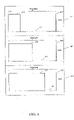
- FIG. 4 includes charts illustrating example on and off portions of a cycle for various duty cycles.
- time is shown along an x-axis and output voltage is shown along a y-axis.
- the charts show idealized output voltages, as for example in most embodiments rises and falls in output voltage will take place during discrete periods of time.
- a first chart 411 illustrates a 25% duty cycle, with a high output voltage during a time period 413, a low output voltage during a time period 415, with a return to the high output voltage at an end 417 of the time period 415.
- the time periods 413 and 415 form a complete cycle, with the time period 413 being 25% of the cycle and the time period 415 being 75% of the cycle.
- a second chart 421 illustrates a 50% duty cycle, with a high output voltage during a time period 423, a low output voltage during a time period 425, with a return to the high output voltage at an end 427 of the time period 425.
- the time periods 423 and 425 form a complete cycle, with the time period 423 and the time period 425 each being 50% of the cycle.
- a third chart 431 illustrates a 75% duty cycle, with a high output voltage during a time period 433, a low output voltage during a time period 435, with a return to the high output voltage at an end 437 of the time period 435.
- the time periods 433 and 435 form a complete cycle, with the time period 433 being 75% of the cycle and the time period 435 being 25% of the cycle.
- the power block 300 includes a battery 317.
- the battery 317 may be separate from the power block 300.
- the battery 317 also may provide DC power to the pulse width modulator 323, with a first power switch 321 selectably choosing either the AC sourced power provided by the DC/DC converter 313 or DC power for modulation by the pulse width modulator 323.
- the first power switch 321 selects the AC sourced power or the battery power based on a control signal provided by a control block, for example control block 217 as discussed with respect to FIG. 2 .
- the first power switch 321 is not used, with an output of the battery 317 and an output of the DC/DC power converter 313 connected in parallel, with both the DC/DC power converter 313 output and the battery 317 output presenting a high impedance.
- the power block 300 may also include a battery charger module 315.
- the battery charger module 315 may be external to the power block.
- the battery charger module 315 includes battery charging circuitry for charging the battery 317 using power from the AC/DC converter 311.
- the AC/DC power converter 311 and the battery 317 are also coupled to a second power switch 319.
- the second power switch 319 provides power for use by various circuit elements, for example circuitry of the control block 217 and monitor block 219 of the generator unit 213 of FIG. 2 .
- FIG. 5 is a flow diagram of a process for determining adjustments to a duty cycle, which is not claimed as such, but nevertheless illustrates the intended operation of the claimed system.
- the process is performed by circuitry, which may be in the form of a processor.
- the process is performed by the control block 217 of FIG. 2 , or by a programmable processor of the control block 217 of FIG. 2 .
- the process compares actual temperature of a heating segment of a catheter, or temperature about a heating segment of a catheter, with a desired temperature.
- the temperature about the heating segment of the catheter may be provided by a temperature sensor located in the catheter near the heating segment, for example.
- the desired temperature may be a constant temperature in some embodiments.
- the desired temperature may be enterable by a user into, for example, the generator unit 213 of FIG. 2 , with an entered temperature received by the control block 217 of FIG. 2 .
- the process determines if the actual temperature is greater than the desired temperature plus a first offset value.
- an offset value which may be programmable, may be useful in avoiding, for example, excessive frequency of changes in the duty cycle, while generally maintaining the actual temperature in a desired temperature band. If the actual temperature is greater than the desired temperature plus the offset value, the process continues to block 515, otherwise the process continues to block 517.
- the process decreases the duty cycle, for example by a set amount, down to a minimum, which is greater than 0%
- the process thereafter returns.
- the process determines if the actual temperature is less than the desired temperature minus a second offset value.
- the second offset value may be the same as the first offset value.
- the second offset value is greater than the first offset value, or less than the first offset value. If the actual temperature is less than the desired temperature minus the offset value, the process continues to block 519, otherwise the process returns.
- the process increases the duty cycle, for example by a set amount, up to a maximum, which is less than 100%
- the process thereafter returns.
- FIG. 6 is a flow diagram of a process for determining whether to use AC sourced power or battery sourced power, which is not claimed as such, but nevertheless illustrates the intended operation of the claimed system.
- the process is performed by circuitry, which may be in the form of a processor.
- the process is performed by the control block 217 of FIG. 2 , or by a programmable processor of the control block 217 of FIG. 2 .
- the process is performed before power is applied to a heating segment of a catheter, or while power is applied to the heating segment, or both before power is applied to the heating segment and while power is applied to the heating segment.
- the process determines if AC sourced power is available.
- the process may determine whether AC sourced power is available based on a signal provided by, for example, the power block 215 of the generator unit 213 of FIG. 2 . If AC sourced power is available the process continues to block 613, otherwise the process continues to block 615.
- the process uses AC sourced power to supply DC power to be modulated for provision to the heating segment of the catheter.
- the process also utilizes AC sourced power, with generally the AC sourced power converted to DC by an AC/DC power converter, for powering of circuitry and, optionally for charging of the battery. The process thereafter returns.
- the process uses battery sourced power to supply DC power to be modulated for provision to the heating segment of the catheter.
- the process may also utilize the battery sourced power for powering of circuitry, and command ceasing of charging of the battery. The process thereafter returns.
Landscapes
- Health & Medical Sciences (AREA)
- Surgery (AREA)
- Life Sciences & Earth Sciences (AREA)
- Engineering & Computer Science (AREA)
- Veterinary Medicine (AREA)
- General Health & Medical Sciences (AREA)
- Nuclear Medicine, Radiotherapy & Molecular Imaging (AREA)
- Public Health (AREA)
- Biomedical Technology (AREA)
- Heart & Thoracic Surgery (AREA)
- Medical Informatics (AREA)
- Molecular Biology (AREA)
- Animal Behavior & Ethology (AREA)
- Otolaryngology (AREA)
- Plasma & Fusion (AREA)
- Physics & Mathematics (AREA)
- Oral & Maxillofacial Surgery (AREA)
- Pathology (AREA)
- Surgical Instruments (AREA)
- Charge And Discharge Circuits For Batteries Or The Like (AREA)
- Thermotherapy And Cooling Therapy Devices (AREA)
Claims (10)
- Medizinisches Behandlungssystem (10), umfassend:einen Katheterschaft (12), umfassend ein proximales Ende, ein distales Ende, einen Griff an dem proximalen Ende und ein Heizsegment (15) in Richtung des distalen Endes, wobei das Heizsegment (15) ein Heizelement (20) umfasst, das konfiguriert ist, um Gewebe abzutragen;einen Wechselstrom-zu-Gleichstrom-Leistungswandler (AC/DC-Leistungswandler) (311), der konfiguriert ist, um eine Wechselstromleistung (AC-Leistung) in eine Gleichstromleistung (DC-Leistung) zu wandeln;einen Leistungswandler (313), der konfiguriert ist, um einen Gleichstromleistungspegel der Gleichstromleistung in einen unterschiedlichen Gleichstromleistungspegel zu wandeln;einen Pulsweitenmodulator (323), der konfiguriert ist, um den unterschiedlichen Gleichstromleistungspegel zu modulieren und Gleichstromleistungsimpulse an das Heizelement (20) zu liefern; undeinen Pulsweitenmodulation-Treiber (PWM-Treiber) (325), der konfiguriert ist, um Signale bereitzustellen, die dem Pulsweitenmodulator (323) befehlen, eingeschaltet und ausgeschaltet zu werden, um die Gleichstromleistungsimpulse zu erzeugen.
- Medizinisches Behandlungssystem (10) nach Anspruch 1, wobei die Gleichstromleistungsimpulse einen minimalen Arbeitszyklus von mehr als 0 % und einen maximalen Arbeitszyklus von weniger als 100 % umfassen.
- Medizinisches Behandlungssystem (10) nach Anspruch 2, wobei der PWM-Treiber (325) konfiguriert ist, um dem Pulsweitenmodulator (323) zu befehlen, einen Arbeitszyklus der Gleichstromleistungsimpulse als Reaktion darauf, dass eine erfasste Temperatur von einem Temperatursensor größer als eine gewünschte Temperatur plus einem ersten Versatzwert ist, zu verringern, und wobei der PWM-Treiber (325) konfiguriert ist, um dem Pulsweitenmodulator (323) zu befehlen, den Arbeitszyklus der Gleichstromleistungsimpulse als Reaktion darauf, dass die erfasste Temperatur von dem Temperatursensor kleiner als die gewünschte Temperatur minus eines zweiten Versatzwerts ist, zu erhöhen.
- Medizinisches Behandlungssystem (10) nach Anspruch 1, ferner umfassend eine Batterie (225, 317) und einen Schalter (321), der konfiguriert ist, um Leistung von entweder dem Gleichstrom/Wechselstrom-Leistungswandler (311) oder der Batterie (225, 317) an den Pulsweitenmodulator (323) schaltbar bereitzustellen.
- Medizinisches Behandlungssystem (10) nach Anspruch 4, wobei der Gleichstrom/Wechselstrom-Leistungswandler (311) und die Batterie (225, 317) zu dem Schalter (321) parallel gekoppelt sind.
- Medizinisches Behandlungssystem (10) nach einem der Ansprüche 4 oder 5, wobei der Leistungswandler (313) zwischen dem Gleichstrom/Wechselstrom-Leistungswandler (311) und dem Schalter (321) gekoppelt ist.
- Medizinisches Behandlungssystem (10) nach einem der Ansprüche 1 bis 6, wobei das Heizelement (20) eine Widerstandsspule ist.
- Medizinisches Behandlungssystem (10) nach einem der Ansprüche 1 bis 7, wobei das Heizelement (20) aus mindestens einem von Nickel-Chrom, einer Nickel-Eisen-Legierung, Kupfer, Edelstahl, Titan oder Zirkonium aufgebaut ist.
- Medizinisches Behandlungssystem (10) nach einem der Ansprüche 1 bis 8, wobei das Heizelement (20) aus einem Material aufgebaut ist, aus dem die Temperatur in Abhängigkeit von einer Impedanz indirekt gemessen wird, und wobei das medizinische System einen Temperatursensor umfasst, der in oder angrenzend an das Heizsegment gelegen ist.
- Medizinisches Behandlungssystem (10) nach Anspruch 7 oder 8 oder 9, wenn abhängig von Anspruch 7, ferner umfassend eine Kunststoffabdeckung, innerhalb der die Widerstandsspule untergebracht ist.
Applications Claiming Priority (2)
| Application Number | Priority Date | Filing Date | Title |
|---|---|---|---|
| US14/038,827 US10448986B2 (en) | 2013-09-27 | 2013-09-27 | Electrosurgical medical device with power modulation |
| EP14184088.4A EP2853216B1 (de) | 2013-09-27 | 2014-09-09 | Elektrochirurgische medizinische Vorrichtung mit Leistungsmodulation |
Related Parent Applications (1)
| Application Number | Title | Priority Date | Filing Date |
|---|---|---|---|
| EP14184088.4A Division EP2853216B1 (de) | 2013-09-27 | 2014-09-09 | Elektrochirurgische medizinische Vorrichtung mit Leistungsmodulation |
Publications (2)
| Publication Number | Publication Date |
|---|---|
| EP3572022A1 EP3572022A1 (de) | 2019-11-27 |
| EP3572022B1 true EP3572022B1 (de) | 2023-01-04 |
Family
ID=51589077
Family Applications (2)
| Application Number | Title | Priority Date | Filing Date |
|---|---|---|---|
| EP19173012.6A Active EP3572022B1 (de) | 2013-09-27 | 2014-09-09 | Elektrochirurgische medizinische vorrichtung mit leistungsmodulation |
| EP14184088.4A Active EP2853216B1 (de) | 2013-09-27 | 2014-09-09 | Elektrochirurgische medizinische Vorrichtung mit Leistungsmodulation |
Family Applications After (1)
| Application Number | Title | Priority Date | Filing Date |
|---|---|---|---|
| EP14184088.4A Active EP2853216B1 (de) | 2013-09-27 | 2014-09-09 | Elektrochirurgische medizinische Vorrichtung mit Leistungsmodulation |
Country Status (7)
| Country | Link |
|---|---|
| US (3) | US10448986B2 (de) |
| EP (2) | EP3572022B1 (de) |
| JP (1) | JP2015066448A (de) |
| KR (1) | KR20150035428A (de) |
| CN (1) | CN104510525B (de) |
| BR (1) | BR102014023774A2 (de) |
| IL (1) | IL234374A0 (de) |
Families Citing this family (91)
| Publication number | Priority date | Publication date | Assignee | Title |
|---|---|---|---|---|
| US11229472B2 (en) | 2001-06-12 | 2022-01-25 | Cilag Gmbh International | Modular battery powered handheld surgical instrument with multiple magnetic position sensors |
| US9089360B2 (en) | 2008-08-06 | 2015-07-28 | Ethicon Endo-Surgery, Inc. | Devices and techniques for cutting and coagulating tissue |
| US8663220B2 (en) | 2009-07-15 | 2014-03-04 | Ethicon Endo-Surgery, Inc. | Ultrasonic surgical instruments |
| US11090104B2 (en) | 2009-10-09 | 2021-08-17 | Cilag Gmbh International | Surgical generator for ultrasonic and electrosurgical devices |
| US10441345B2 (en) | 2009-10-09 | 2019-10-15 | Ethicon Llc | Surgical generator for ultrasonic and electrosurgical devices |
| US8469981B2 (en) | 2010-02-11 | 2013-06-25 | Ethicon Endo-Surgery, Inc. | Rotatable cutting implement arrangements for ultrasonic surgical instruments |
| WO2013119545A1 (en) | 2012-02-10 | 2013-08-15 | Ethicon-Endo Surgery, Inc. | Robotically controlled surgical instrument |
| US9439668B2 (en) | 2012-04-09 | 2016-09-13 | Ethicon Endo-Surgery, Llc | Switch arrangements for ultrasonic surgical instruments |
| US20140005705A1 (en) | 2012-06-29 | 2014-01-02 | Ethicon Endo-Surgery, Inc. | Surgical instruments with articulating shafts |
| US9408622B2 (en) | 2012-06-29 | 2016-08-09 | Ethicon Endo-Surgery, Llc | Surgical instruments with articulating shafts |
| US9198714B2 (en) | 2012-06-29 | 2015-12-01 | Ethicon Endo-Surgery, Inc. | Haptic feedback devices for surgical robot |
| US9351754B2 (en) | 2012-06-29 | 2016-05-31 | Ethicon Endo-Surgery, Llc | Ultrasonic surgical instruments with distally positioned jaw assemblies |
| US9393037B2 (en) | 2012-06-29 | 2016-07-19 | Ethicon Endo-Surgery, Llc | Surgical instruments with articulating shafts |
| US9326788B2 (en) | 2012-06-29 | 2016-05-03 | Ethicon Endo-Surgery, Llc | Lockout mechanism for use with robotic electrosurgical device |
| US20140005702A1 (en) | 2012-06-29 | 2014-01-02 | Ethicon Endo-Surgery, Inc. | Ultrasonic surgical instruments with distally positioned transducers |
| US9226767B2 (en) | 2012-06-29 | 2016-01-05 | Ethicon Endo-Surgery, Inc. | Closed feedback control for electrosurgical device |
| US9095367B2 (en) | 2012-10-22 | 2015-08-04 | Ethicon Endo-Surgery, Inc. | Flexible harmonic waveguides/blades for surgical instruments |
| US20140135804A1 (en) | 2012-11-15 | 2014-05-15 | Ethicon Endo-Surgery, Inc. | Ultrasonic and electrosurgical devices |
| US9814514B2 (en) | 2013-09-13 | 2017-11-14 | Ethicon Llc | Electrosurgical (RF) medical instruments for cutting and coagulating tissue |
| US9265926B2 (en) | 2013-11-08 | 2016-02-23 | Ethicon Endo-Surgery, Llc | Electrosurgical devices |
| GB2521228A (en) | 2013-12-16 | 2015-06-17 | Ethicon Endo Surgery Inc | Medical device |
| US9795436B2 (en) | 2014-01-07 | 2017-10-24 | Ethicon Llc | Harvesting energy from a surgical generator |
| US9554854B2 (en) | 2014-03-18 | 2017-01-31 | Ethicon Endo-Surgery, Llc | Detecting short circuits in electrosurgical medical devices |
| DK3122414T3 (da) | 2014-03-26 | 2021-05-31 | Venclose Inc | Kabelenhed |
| US10092310B2 (en) | 2014-03-27 | 2018-10-09 | Ethicon Llc | Electrosurgical devices |
| US9737355B2 (en) | 2014-03-31 | 2017-08-22 | Ethicon Llc | Controlling impedance rise in electrosurgical medical devices |
| US9913680B2 (en) | 2014-04-15 | 2018-03-13 | Ethicon Llc | Software algorithms for electrosurgical instruments |
| WO2015167623A2 (en) * | 2014-04-29 | 2015-11-05 | William Dean Wallace | Treatment methods and portable surgical devices for treating neoplastic and hyperplastic cells in the cervix and other dermatologically or surface related disorders |
| US10285724B2 (en) | 2014-07-31 | 2019-05-14 | Ethicon Llc | Actuation mechanisms and load adjustment assemblies for surgical instruments |
| US10639092B2 (en) | 2014-12-08 | 2020-05-05 | Ethicon Llc | Electrode configurations for surgical instruments |
| US10245095B2 (en) | 2015-02-06 | 2019-04-02 | Ethicon Llc | Electrosurgical instrument with rotation and articulation mechanisms |
| US10222575B2 (en) * | 2015-02-06 | 2019-03-05 | Flir Systems, Inc. | Lens heater to maintain thermal equilibrium in an infrared imaging system |
| US10595929B2 (en) | 2015-03-24 | 2020-03-24 | Ethicon Llc | Surgical instruments with firing system overload protection mechanisms |
| US10034704B2 (en) | 2015-06-30 | 2018-07-31 | Ethicon Llc | Surgical instrument with user adaptable algorithms |
| US11129669B2 (en) | 2015-06-30 | 2021-09-28 | Cilag Gmbh International | Surgical system with user adaptable techniques based on tissue type |
| US11051873B2 (en) | 2015-06-30 | 2021-07-06 | Cilag Gmbh International | Surgical system with user adaptable techniques employing multiple energy modalities based on tissue parameters |
| US10898256B2 (en) | 2015-06-30 | 2021-01-26 | Ethicon Llc | Surgical system with user adaptable techniques based on tissue impedance |
| US10765470B2 (en) | 2015-06-30 | 2020-09-08 | Ethicon Llc | Surgical system with user adaptable techniques employing simultaneous energy modalities based on tissue parameters |
| US11446078B2 (en) | 2015-07-20 | 2022-09-20 | Megadyne Medical Products, Inc. | Electrosurgical wave generator |
| ITUB20152393A1 (it) * | 2015-07-22 | 2017-01-22 | Otech Ind S R L | Apparecchio di elettrochirurgia per eseguire un’azione di taglio su tessuti di un corpo di un paziente umano od animale. |
| US20170086909A1 (en) | 2015-09-30 | 2017-03-30 | Ethicon Endo-Surgery, Llc | Frequency agile generator for a surgical instrument |
| US10595930B2 (en) | 2015-10-16 | 2020-03-24 | Ethicon Llc | Electrode wiping surgical device |
| US10575892B2 (en) * | 2015-12-31 | 2020-03-03 | Ethicon Llc | Adapter for electrical surgical instruments |
| CN105662575B (zh) * | 2016-01-04 | 2019-04-16 | 浙江伽奈维医疗科技有限公司 | 射频消融设备 |
| US11229471B2 (en) | 2016-01-15 | 2022-01-25 | Cilag Gmbh International | Modular battery powered handheld surgical instrument with selective application of energy based on tissue characterization |
| US11129670B2 (en) | 2016-01-15 | 2021-09-28 | Cilag Gmbh International | Modular battery powered handheld surgical instrument with selective application of energy based on button displacement, intensity, or local tissue characterization |
| EP3213708B1 (de) * | 2016-01-15 | 2019-02-27 | Cook Medical Technologies LLC | Medizinische vorrichtung |
| US10716615B2 (en) | 2016-01-15 | 2020-07-21 | Ethicon Llc | Modular battery powered handheld surgical instrument with curved end effectors having asymmetric engagement between jaw and blade |
| US11134978B2 (en) | 2016-01-15 | 2021-10-05 | Cilag Gmbh International | Modular battery powered handheld surgical instrument with self-diagnosing control switches for reusable handle assembly |
| US20170202600A1 (en) * | 2016-01-15 | 2017-07-20 | Cook Medical Technologies Llc | Medical device |
| US12193698B2 (en) | 2016-01-15 | 2025-01-14 | Cilag Gmbh International | Method for self-diagnosing operation of a control switch in a surgical instrument system |
| FR3047163A1 (fr) * | 2016-02-01 | 2017-08-04 | Miravas | Dispositif pour le traitement thermique de vaisseaux, et procede associe |
| US10555769B2 (en) | 2016-02-22 | 2020-02-11 | Ethicon Llc | Flexible circuits for electrosurgical instrument |
| US10485607B2 (en) | 2016-04-29 | 2019-11-26 | Ethicon Llc | Jaw structure with distal closure for electrosurgical instruments |
| US10646269B2 (en) | 2016-04-29 | 2020-05-12 | Ethicon Llc | Non-linear jaw gap for electrosurgical instruments |
| US10456193B2 (en) | 2016-05-03 | 2019-10-29 | Ethicon Llc | Medical device with a bilateral jaw configuration for nerve stimulation |
| US10376305B2 (en) | 2016-08-05 | 2019-08-13 | Ethicon Llc | Methods and systems for advanced harmonic energy |
| US11266430B2 (en) | 2016-11-29 | 2022-03-08 | Cilag Gmbh International | End effector control and calibration |
| CN108066003A (zh) * | 2017-12-29 | 2018-05-25 | 浙江归创医疗器械有限公司 | 消融导管 |
| CN111214289A (zh) * | 2019-12-24 | 2020-06-02 | 杭州诺诚医疗器械有限公司 | 射频能量发生装置以及射频消融系统 |
| US12023086B2 (en) | 2019-12-30 | 2024-07-02 | Cilag Gmbh International | Electrosurgical instrument for delivering blended energy modalities to tissue |
| US12114912B2 (en) | 2019-12-30 | 2024-10-15 | Cilag Gmbh International | Non-biased deflectable electrode to minimize contact between ultrasonic blade and electrode |
| US11452525B2 (en) | 2019-12-30 | 2022-09-27 | Cilag Gmbh International | Surgical instrument comprising an adjustment system |
| US12336747B2 (en) | 2019-12-30 | 2025-06-24 | Cilag Gmbh International | Method of operating a combination ultrasonic / bipolar RF surgical device with a combination energy modality end-effector |
| US11937863B2 (en) | 2019-12-30 | 2024-03-26 | Cilag Gmbh International | Deflectable electrode with variable compression bias along the length of the deflectable electrode |
| US12076006B2 (en) | 2019-12-30 | 2024-09-03 | Cilag Gmbh International | Surgical instrument comprising an orientation detection system |
| US11696776B2 (en) | 2019-12-30 | 2023-07-11 | Cilag Gmbh International | Articulatable surgical instrument |
| US12053224B2 (en) | 2019-12-30 | 2024-08-06 | Cilag Gmbh International | Variation in electrode parameters and deflectable electrode to modify energy density and tissue interaction |
| US12064109B2 (en) | 2019-12-30 | 2024-08-20 | Cilag Gmbh International | Surgical instrument comprising a feedback control circuit |
| US12082808B2 (en) | 2019-12-30 | 2024-09-10 | Cilag Gmbh International | Surgical instrument comprising a control system responsive to software configurations |
| US11779387B2 (en) | 2019-12-30 | 2023-10-10 | Cilag Gmbh International | Clamp arm jaw to minimize tissue sticking and improve tissue control |
| US11779329B2 (en) | 2019-12-30 | 2023-10-10 | Cilag Gmbh International | Surgical instrument comprising a flex circuit including a sensor system |
| US11812957B2 (en) | 2019-12-30 | 2023-11-14 | Cilag Gmbh International | Surgical instrument comprising a signal interference resolution system |
| US11660089B2 (en) | 2019-12-30 | 2023-05-30 | Cilag Gmbh International | Surgical instrument comprising a sensing system |
| US12262937B2 (en) | 2019-12-30 | 2025-04-01 | Cilag Gmbh International | User interface for surgical instrument with combination energy modality end-effector |
| US11707318B2 (en) | 2019-12-30 | 2023-07-25 | Cilag Gmbh International | Surgical instrument with jaw alignment features |
| US11986234B2 (en) | 2019-12-30 | 2024-05-21 | Cilag Gmbh International | Surgical system communication pathways |
| US11911063B2 (en) | 2019-12-30 | 2024-02-27 | Cilag Gmbh International | Techniques for detecting ultrasonic blade to electrode contact and reducing power to ultrasonic blade |
| US20210196361A1 (en) | 2019-12-30 | 2021-07-01 | Ethicon Llc | Electrosurgical instrument with monopolar and bipolar energy capabilities |
| US11786291B2 (en) | 2019-12-30 | 2023-10-17 | Cilag Gmbh International | Deflectable support of RF energy electrode with respect to opposing ultrasonic blade |
| US11950797B2 (en) | 2019-12-30 | 2024-04-09 | Cilag Gmbh International | Deflectable electrode with higher distal bias relative to proximal bias |
| US12343063B2 (en) | 2019-12-30 | 2025-07-01 | Cilag Gmbh International | Multi-layer clamp arm pad for enhanced versatility and performance of a surgical device |
| US11986201B2 (en) | 2019-12-30 | 2024-05-21 | Cilag Gmbh International | Method for operating a surgical instrument |
| US11944366B2 (en) | 2019-12-30 | 2024-04-02 | Cilag Gmbh International | Asymmetric segmented ultrasonic support pad for cooperative engagement with a movable RF electrode |
| US20210196357A1 (en) | 2019-12-30 | 2021-07-01 | Ethicon Llc | Electrosurgical instrument with asynchronous energizing electrodes |
| US12349961B2 (en) | 2019-12-30 | 2025-07-08 | Cilag Gmbh International | Electrosurgical instrument with electrodes operable in bipolar and monopolar modes |
| CN113842200A (zh) * | 2020-11-30 | 2021-12-28 | 杭州德诺电生理医疗科技有限公司 | 一种脉冲消融仪及其控制方法 |
| US12622716B2 (en) | 2021-08-05 | 2026-05-12 | Cardiovascular Systems, Inc. | Systems, devices and methods for generating patterns of voltage pulses and electrical arcs between spaced-apart electrode pairs in intravascular lithotripsy |
| US20240285331A1 (en) * | 2023-02-24 | 2024-08-29 | Maquet Cardiovascular Llc | Systems and methods for power control for a therapeutic tool |
| WO2025078997A1 (en) * | 2023-10-11 | 2025-04-17 | Medtronic Advanced Energy Llc | Tissue temperature detection for bipolar sealing using infrared temperature sensor |
| JP2026068797A (ja) * | 2024-10-11 | 2026-04-23 | 株式会社アドメテック | 温度制御が可能な加熱治療システム |
Family Cites Families (63)
| Publication number | Priority date | Publication date | Assignee | Title |
|---|---|---|---|---|
| US4196734A (en) * | 1978-02-16 | 1980-04-08 | Valleylab, Inc. | Combined electrosurgery/cautery system and method |
| JPS5876345A (ja) | 1981-10-30 | 1983-05-09 | Toyota Motor Corp | 車輛用デフオガ装置 |
| US4869248A (en) | 1987-04-17 | 1989-09-26 | Narula Onkar S | Method and apparatus for localized thermal ablation |
| US4835410A (en) * | 1988-02-26 | 1989-05-30 | Black & Decker Inc. | Dual-mode corded/cordless system for power-operated devices |
| US4945912A (en) * | 1988-11-25 | 1990-08-07 | Sensor Electronics, Inc. | Catheter with radiofrequency heating applicator |
| EP0500215A1 (de) * | 1991-01-30 | 1992-08-26 | ANGELASE, Inc. | Verfahren und Apparat zur Messung von Tachyarrhythmien |
| US5573533A (en) | 1992-04-10 | 1996-11-12 | Medtronic Cardiorhythm | Method and system for radiofrequency ablation of cardiac tissue |
| US5484400A (en) * | 1992-08-12 | 1996-01-16 | Vidamed, Inc. | Dual channel RF delivery system |
| US5517989A (en) * | 1994-04-01 | 1996-05-21 | Cardiometrics, Inc. | Guidewire assembly |
| EP0957792A4 (de) * | 1995-05-02 | 2000-09-20 | Heart Rhythm Tech Inc | Anordnung zur steuerung einem patienten zugeführten ablationsenergie |
| JP3415718B2 (ja) | 1996-05-13 | 2003-06-09 | シャープ株式会社 | ヒータ温度制御方法および装置 |
| US5836943A (en) * | 1996-08-23 | 1998-11-17 | Team Medical, L.L.C. | Electrosurgical generator |
| ES2353846T3 (es) * | 1997-04-11 | 2011-03-07 | United States Surgical Corporation | Aparato para ablación con rf y controlador del mismo. |
| US6012457A (en) * | 1997-07-08 | 2000-01-11 | The Regents Of The University Of California | Device and method for forming a circumferential conduction block in a pulmonary vein |
| US6070590A (en) * | 1998-02-12 | 2000-06-06 | Pacesetter, Inc. | Method of using electrical energy to produce temporary conduction block for defibrillation and cardioversion |
| US6558378B2 (en) * | 1998-05-05 | 2003-05-06 | Cardiac Pacemakers, Inc. | RF ablation system and method having automatic temperature control |
| US8551082B2 (en) | 1998-05-08 | 2013-10-08 | Cytyc Surgical Products | Radio-frequency generator for powering an ablation device |
| US6123084A (en) * | 1998-12-18 | 2000-09-26 | Eclipse Surgical Technologies, Inc. | Method for improving blood flow in the heart |
| CN100506183C (zh) * | 2000-05-12 | 2009-07-01 | 卡帝玛股份有限公司 | 利用消融导管对心脏组织进行射频能量的有效输送的系统 |
| US7252664B2 (en) | 2000-05-12 | 2007-08-07 | Cardima, Inc. | System and method for multi-channel RF energy delivery with coagulum reduction |
| US7789876B2 (en) | 2000-08-14 | 2010-09-07 | Tyco Healthcare Group, Lp | Method and apparatus for positioning a catheter relative to an anatomical junction |
| US20030130713A1 (en) | 2001-05-21 | 2003-07-10 | Stewart Mark T. | Trans-septal catheter with retention mechanism |
| US6893436B2 (en) | 2002-01-03 | 2005-05-17 | Afx, Inc. | Ablation instrument having a flexible distal portion |
| US7041096B2 (en) * | 2002-10-24 | 2006-05-09 | Synergetics Usa, Inc. | Electrosurgical generator apparatus |
| US20040158237A1 (en) | 2003-02-11 | 2004-08-12 | Marwan Abboud | Multi-energy ablation station |
| JP4124041B2 (ja) * | 2003-07-18 | 2008-07-23 | 日立工機株式会社 | 充電機能付き直流電源装置 |
| US7720549B2 (en) * | 2004-04-06 | 2010-05-18 | Oncostim, Inc. | Partially implantable system for the electrical treatment of abnormal tissue growth |
| US8945116B2 (en) * | 2004-05-17 | 2015-02-03 | Boston Scientific Scimed, Inc. | Mapping and ablation method for the treatment of ventricular tachycardia |
| CN1296014C (zh) | 2004-06-17 | 2007-01-24 | 上海交通大学 | 水冷式射频肿瘤消融治疗系统 |
| GB0502384D0 (en) | 2005-02-04 | 2005-03-16 | Instrumedical Ltd | Electro-surgical needle apparatus |
| US8197472B2 (en) * | 2005-03-25 | 2012-06-12 | Maquet Cardiovascular, Llc | Tissue welding and cutting apparatus and method |
| US7799019B2 (en) | 2005-05-10 | 2010-09-21 | Vivant Medical, Inc. | Reinforced high strength microwave antenna |
| US20090043365A1 (en) * | 2005-07-18 | 2009-02-12 | Kolis Scientific, Inc. | Methods, apparatuses, and systems for reducing intraocular pressure as a means of preventing or treating open-angle glaucoma |
| US8721634B2 (en) * | 2005-07-21 | 2014-05-13 | Covidien Lp | Apparatus and method for ensuring thermal treatment of a hollow anatomical structure |
| US8382748B2 (en) * | 2006-01-03 | 2013-02-26 | Donald J. Geisel | High efficiency, precision electrosurgical apparatus and method |
| US7513896B2 (en) | 2006-01-24 | 2009-04-07 | Covidien Ag | Dual synchro-resonant electrosurgical apparatus with bi-directional magnetic coupling |
| US8226648B2 (en) | 2007-12-31 | 2012-07-24 | St. Jude Medical, Atrial Fibrillation Division, Inc. | Pressure-sensitive flexible polymer bipolar electrode |
| CN100998500A (zh) | 2007-01-11 | 2007-07-18 | 上海交通大学 | 前列腺消融用尿道温度多点监控导管 |
| US20120271289A1 (en) * | 2007-01-22 | 2012-10-25 | Syneron Medical Ltd. | Hair removal devices and methods |
| US8641704B2 (en) | 2007-05-11 | 2014-02-04 | Medtronic Ablation Frontiers Llc | Ablation therapy system and method for treating continuous atrial fibrillation |
| WO2009036472A1 (en) | 2007-09-14 | 2009-03-19 | Lazure Technologies, Llc | Prostate cancer ablation |
| JP2009086963A (ja) | 2007-09-28 | 2009-04-23 | Casio Comput Co Ltd | 温度制御装置及び温度制御方法 |
| CN101156803A (zh) | 2007-11-23 | 2008-04-09 | 北京市亚可康达技术研究所 | 便携式高频电刀控制器 |
| US20110224663A1 (en) | 2008-04-23 | 2011-09-15 | Tornier, Inc. | Control circuitry for a tissue ablation system |
| US8349174B2 (en) * | 2008-07-23 | 2013-01-08 | Baxter International Inc. | Portable power dialysis machine |
| EP2370014A1 (de) | 2008-10-28 | 2011-10-05 | Smith & Nephew, Inc. | Elektrochirurgische vorrichtung mit kontrollierbarem elektrofeld-profil |
| US8574187B2 (en) | 2009-03-09 | 2013-11-05 | Arthrocare Corporation | System and method of an electrosurgical controller with output RF energy control |
| WO2010141417A2 (en) | 2009-06-01 | 2010-12-09 | Mayo Foundation For Medical Education And Research | Systems and methods for impairing smooth muscle tissue function |
| US8512335B2 (en) * | 2010-05-20 | 2013-08-20 | Curo Medical, Inc. | High frequency alternating current medical device with self-limiting conductive material and method |
| US9044232B2 (en) | 2010-01-05 | 2015-06-02 | Curo Medical, Inc. | Medical heating device and method with self-limiting electrical heating element |
| EP2417925B1 (de) * | 2010-08-12 | 2016-12-07 | Immersion Corporation | Elektrochirurgisches Werkzeug mit taktiler Rückmeldung |
| WO2012033860A1 (en) | 2010-09-07 | 2012-03-15 | Boston Scientific Scimed, Inc. | Self-powered ablation catheter for renal denervation |
| US9055957B2 (en) | 2010-12-23 | 2015-06-16 | Covidien Lp | Microwave field-detecting needle assemblies, methods of manufacturing same, methods of adjusting an ablation field radiating into tissue using same, and systems including same |
| US9636167B2 (en) * | 2011-05-31 | 2017-05-02 | Covidien Lp | Surgical device with DC power connection |
| US8706258B2 (en) * | 2011-08-08 | 2014-04-22 | Medamp Electronics, Llc | Method and apparatus for treating cancer |
| US9099863B2 (en) * | 2011-09-09 | 2015-08-04 | Covidien Lp | Surgical generator and related method for mitigating overcurrent conditions |
| US20140350541A1 (en) | 2011-12-13 | 2014-11-27 | Lazure Scientific, Inc. | Control and delivery of electric fields via an electrode array |
| CN202666197U (zh) | 2012-03-14 | 2013-01-16 | 张树堂 | 多功能电磁银离子治疗射频消融仪 |
| US9151680B2 (en) * | 2012-06-22 | 2015-10-06 | Covidien Lp | Microwave thermometry for microwave ablation systems |
| US20140207124A1 (en) * | 2013-01-23 | 2014-07-24 | Ethicon Endo-Surgery, Inc. | Surgical instrument with selectable integral or external power source |
| US9717551B2 (en) * | 2013-02-21 | 2017-08-01 | Carefusion 2200, Inc. | Intravertebral tissue ablation device and method |
| GB2514100B (en) | 2013-05-08 | 2020-04-01 | Creo Medical Ltd | Apparatus for Controlling Power Delivered by Electrosurgical Probe |
| US9872719B2 (en) | 2013-07-24 | 2018-01-23 | Covidien Lp | Systems and methods for generating electrosurgical energy using a multistage power converter |
-
2013
- 2013-09-27 US US14/038,827 patent/US10448986B2/en active Active
-
2014
- 2014-08-31 IL IL234374A patent/IL234374A0/en unknown
- 2014-09-09 EP EP19173012.6A patent/EP3572022B1/de active Active
- 2014-09-09 EP EP14184088.4A patent/EP2853216B1/de active Active
- 2014-09-25 BR BR102014023774A patent/BR102014023774A2/pt not_active IP Right Cessation
- 2014-09-25 KR KR20140128152A patent/KR20150035428A/ko not_active Ceased
- 2014-09-26 JP JP2014196441A patent/JP2015066448A/ja active Pending
- 2014-09-26 CN CN201410502631.3A patent/CN104510525B/zh active Active
-
2019
- 2019-10-18 US US16/657,770 patent/US20200046415A1/en not_active Abandoned
-
2022
- 2022-05-23 US US17/664,580 patent/US20220354563A1/en active Pending
Also Published As
| Publication number | Publication date |
|---|---|
| US20200046415A1 (en) | 2020-02-13 |
| JP2015066448A (ja) | 2015-04-13 |
| EP2853216A1 (de) | 2015-04-01 |
| US20150094703A1 (en) | 2015-04-02 |
| EP2853216B1 (de) | 2019-05-08 |
| US10448986B2 (en) | 2019-10-22 |
| KR20150035428A (ko) | 2015-04-06 |
| US20220354563A1 (en) | 2022-11-10 |
| CN104510525B (zh) | 2018-01-05 |
| BR102014023774A2 (pt) | 2015-10-06 |
| CN104510525A (zh) | 2015-04-15 |
| EP3572022A1 (de) | 2019-11-27 |
| IL234374A0 (en) | 2014-11-30 |
Similar Documents
| Publication | Publication Date | Title |
|---|---|---|
| US20220354563A1 (en) | Electrosurgical medical device with power modulation | |
| CN108348285A (zh) | 脊髓组织切除设备、系统和方法 | |
| US20170020598A1 (en) | Electrosurgical wave generator | |
| EP3187135B1 (de) | Medizinische behandlungsvorrichtungen mit anpassbarer länge | |
| US20100130976A1 (en) | Reducing cross-talk effects in an rf electrosurgical device | |
| EP2853214B1 (de) | Medizinische Vorrichtungen mit anpassbarer Länge und/oder anpassbarem Durchmesser | |
| US20170172644A1 (en) | Electrochemical protection of conducting circuit in the body of a patient | |
| GB2536690A (en) | Medical ablation system and method with reduced stray heating | |
| AU2019417426A1 (en) | System and method for measuring heat transfer due to local tissue perfusion prior to an ablation procedure | |
| EP2853215B1 (de) | Medizinische Vorrichtungen mit anpassbarer Länge und/oder anpassbarem Durchmesser | |
| CN104510527B (zh) | 具有可调节长度和/或直径的医疗装置 | |
| CN104510529B (zh) | 具有可调节长度和/或直径的医疗装置 |
Legal Events
| Date | Code | Title | Description |
|---|---|---|---|
| PUAI | Public reference made under article 153(3) epc to a published international application that has entered the european phase |
Free format text: ORIGINAL CODE: 0009012 |
|
| STAA | Information on the status of an ep patent application or granted ep patent |
Free format text: STATUS: REQUEST FOR EXAMINATION WAS MADE |
|
| 17P | Request for examination filed |
Effective date: 20190507 |
|
| AC | Divisional application: reference to earlier application |
Ref document number: 2853216 Country of ref document: EP Kind code of ref document: P |
|
| AK | Designated contracting states |
Kind code of ref document: A1 Designated state(s): AL AT BE BG CH CY CZ DE DK EE ES FI FR GB GR HR HU IE IS IT LI LT LU LV MC MK MT NL NO PL PT RO RS SE SI SK SM TR |
|
| GRAP | Despatch of communication of intention to grant a patent |
Free format text: ORIGINAL CODE: EPIDOSNIGR1 |
|
| STAA | Information on the status of an ep patent application or granted ep patent |
Free format text: STATUS: GRANT OF PATENT IS INTENDED |
|
| RIC1 | Information provided on ipc code assigned before grant |
Ipc: A61B 18/08 20060101ALN20220906BHEP Ipc: A61B 18/00 20060101ALN20220906BHEP Ipc: A61B 18/10 20060101AFI20220906BHEP |
|
| INTG | Intention to grant announced |
Effective date: 20221012 |
|
| GRAS | Grant fee paid |
Free format text: ORIGINAL CODE: EPIDOSNIGR3 |
|
| GRAA | (expected) grant |
Free format text: ORIGINAL CODE: 0009210 |
|
| STAA | Information on the status of an ep patent application or granted ep patent |
Free format text: STATUS: THE PATENT HAS BEEN GRANTED |
|
| AC | Divisional application: reference to earlier application |
Ref document number: 2853216 Country of ref document: EP Kind code of ref document: P |
|
| AK | Designated contracting states |
Kind code of ref document: B1 Designated state(s): AL AT BE BG CH CY CZ DE DK EE ES FI FR GB GR HR HU IE IS IT LI LT LU LV MC MK MT NL NO PL PT RO RS SE SI SK SM TR |
|
| REG | Reference to a national code |
Ref country code: GB Ref legal event code: FG4D |
|
| REG | Reference to a national code |
Ref country code: DE Ref legal event code: R096 Ref document number: 602014086044 Country of ref document: DE |
|
| REG | Reference to a national code |
Ref country code: CH Ref legal event code: EP |
|
| REG | Reference to a national code |
Ref country code: AT Ref legal event code: REF Ref document number: 1541409 Country of ref document: AT Kind code of ref document: T Effective date: 20230115 |
|
| REG | Reference to a national code |
Ref country code: IE Ref legal event code: FG4D |
|
| REG | Reference to a national code |
Ref country code: LT Ref legal event code: MG9D |
|
| REG | Reference to a national code |
Ref country code: NL Ref legal event code: MP Effective date: 20230104 |
|
| REG | Reference to a national code |
Ref country code: AT Ref legal event code: MK05 Ref document number: 1541409 Country of ref document: AT Kind code of ref document: T Effective date: 20230104 |
|
| PG25 | Lapsed in a contracting state [announced via postgrant information from national office to epo] |
Ref country code: NL Free format text: LAPSE BECAUSE OF FAILURE TO SUBMIT A TRANSLATION OF THE DESCRIPTION OR TO PAY THE FEE WITHIN THE PRESCRIBED TIME-LIMIT Effective date: 20230104 |
|
| PG25 | Lapsed in a contracting state [announced via postgrant information from national office to epo] |
Ref country code: RS Free format text: LAPSE BECAUSE OF FAILURE TO SUBMIT A TRANSLATION OF THE DESCRIPTION OR TO PAY THE FEE WITHIN THE PRESCRIBED TIME-LIMIT Effective date: 20230104 Ref country code: PT Free format text: LAPSE BECAUSE OF FAILURE TO SUBMIT A TRANSLATION OF THE DESCRIPTION OR TO PAY THE FEE WITHIN THE PRESCRIBED TIME-LIMIT Effective date: 20230504 Ref country code: NO Free format text: LAPSE BECAUSE OF FAILURE TO SUBMIT A TRANSLATION OF THE DESCRIPTION OR TO PAY THE FEE WITHIN THE PRESCRIBED TIME-LIMIT Effective date: 20230404 Ref country code: LV Free format text: LAPSE BECAUSE OF FAILURE TO SUBMIT A TRANSLATION OF THE DESCRIPTION OR TO PAY THE FEE WITHIN THE PRESCRIBED TIME-LIMIT Effective date: 20230104 Ref country code: LT Free format text: LAPSE BECAUSE OF FAILURE TO SUBMIT A TRANSLATION OF THE DESCRIPTION OR TO PAY THE FEE WITHIN THE PRESCRIBED TIME-LIMIT Effective date: 20230104 Ref country code: HR Free format text: LAPSE BECAUSE OF FAILURE TO SUBMIT A TRANSLATION OF THE DESCRIPTION OR TO PAY THE FEE WITHIN THE PRESCRIBED TIME-LIMIT Effective date: 20230104 Ref country code: ES Free format text: LAPSE BECAUSE OF FAILURE TO SUBMIT A TRANSLATION OF THE DESCRIPTION OR TO PAY THE FEE WITHIN THE PRESCRIBED TIME-LIMIT Effective date: 20230104 Ref country code: AT Free format text: LAPSE BECAUSE OF FAILURE TO SUBMIT A TRANSLATION OF THE DESCRIPTION OR TO PAY THE FEE WITHIN THE PRESCRIBED TIME-LIMIT Effective date: 20230104 |
|
| PG25 | Lapsed in a contracting state [announced via postgrant information from national office to epo] |
Ref country code: SE Free format text: LAPSE BECAUSE OF FAILURE TO SUBMIT A TRANSLATION OF THE DESCRIPTION OR TO PAY THE FEE WITHIN THE PRESCRIBED TIME-LIMIT Effective date: 20230104 Ref country code: PL Free format text: LAPSE BECAUSE OF FAILURE TO SUBMIT A TRANSLATION OF THE DESCRIPTION OR TO PAY THE FEE WITHIN THE PRESCRIBED TIME-LIMIT Effective date: 20230104 Ref country code: IS Free format text: LAPSE BECAUSE OF FAILURE TO SUBMIT A TRANSLATION OF THE DESCRIPTION OR TO PAY THE FEE WITHIN THE PRESCRIBED TIME-LIMIT Effective date: 20230504 Ref country code: GR Free format text: LAPSE BECAUSE OF FAILURE TO SUBMIT A TRANSLATION OF THE DESCRIPTION OR TO PAY THE FEE WITHIN THE PRESCRIBED TIME-LIMIT Effective date: 20230405 Ref country code: FI Free format text: LAPSE BECAUSE OF FAILURE TO SUBMIT A TRANSLATION OF THE DESCRIPTION OR TO PAY THE FEE WITHIN THE PRESCRIBED TIME-LIMIT Effective date: 20230104 |
|
| REG | Reference to a national code |
Ref country code: DE Ref legal event code: R097 Ref document number: 602014086044 Country of ref document: DE |
|
| PG25 | Lapsed in a contracting state [announced via postgrant information from national office to epo] |
Ref country code: SM Free format text: LAPSE BECAUSE OF FAILURE TO SUBMIT A TRANSLATION OF THE DESCRIPTION OR TO PAY THE FEE WITHIN THE PRESCRIBED TIME-LIMIT Effective date: 20230104 Ref country code: RO Free format text: LAPSE BECAUSE OF FAILURE TO SUBMIT A TRANSLATION OF THE DESCRIPTION OR TO PAY THE FEE WITHIN THE PRESCRIBED TIME-LIMIT Effective date: 20230104 Ref country code: EE Free format text: LAPSE BECAUSE OF FAILURE TO SUBMIT A TRANSLATION OF THE DESCRIPTION OR TO PAY THE FEE WITHIN THE PRESCRIBED TIME-LIMIT Effective date: 20230104 Ref country code: DK Free format text: LAPSE BECAUSE OF FAILURE TO SUBMIT A TRANSLATION OF THE DESCRIPTION OR TO PAY THE FEE WITHIN THE PRESCRIBED TIME-LIMIT Effective date: 20230104 Ref country code: CZ Free format text: LAPSE BECAUSE OF FAILURE TO SUBMIT A TRANSLATION OF THE DESCRIPTION OR TO PAY THE FEE WITHIN THE PRESCRIBED TIME-LIMIT Effective date: 20230104 |
|
| PLBE | No opposition filed within time limit |
Free format text: ORIGINAL CODE: 0009261 |
|
| STAA | Information on the status of an ep patent application or granted ep patent |
Free format text: STATUS: NO OPPOSITION FILED WITHIN TIME LIMIT |
|
| PG25 | Lapsed in a contracting state [announced via postgrant information from national office to epo] |
Ref country code: SK Free format text: LAPSE BECAUSE OF FAILURE TO SUBMIT A TRANSLATION OF THE DESCRIPTION OR TO PAY THE FEE WITHIN THE PRESCRIBED TIME-LIMIT Effective date: 20230104 |
|
| 26N | No opposition filed |
Effective date: 20231005 |
|
| PG25 | Lapsed in a contracting state [announced via postgrant information from national office to epo] |
Ref country code: SI Free format text: LAPSE BECAUSE OF FAILURE TO SUBMIT A TRANSLATION OF THE DESCRIPTION OR TO PAY THE FEE WITHIN THE PRESCRIBED TIME-LIMIT Effective date: 20230104 |
|
| REG | Reference to a national code |
Ref country code: CH Ref legal event code: PL |
|
| PG25 | Lapsed in a contracting state [announced via postgrant information from national office to epo] |
Ref country code: LU Free format text: LAPSE BECAUSE OF NON-PAYMENT OF DUE FEES Effective date: 20230909 |
|
| REG | Reference to a national code |
Ref country code: BE Ref legal event code: MM Effective date: 20230930 |
|
| GBPC | Gb: european patent ceased through non-payment of renewal fee |
Effective date: 20230909 |
|
| PG25 | Lapsed in a contracting state [announced via postgrant information from national office to epo] |
Ref country code: LU Free format text: LAPSE BECAUSE OF NON-PAYMENT OF DUE FEES Effective date: 20230909 Ref country code: IT Free format text: LAPSE BECAUSE OF FAILURE TO SUBMIT A TRANSLATION OF THE DESCRIPTION OR TO PAY THE FEE WITHIN THE PRESCRIBED TIME-LIMIT Effective date: 20230104 Ref country code: MC Free format text: LAPSE BECAUSE OF FAILURE TO SUBMIT A TRANSLATION OF THE DESCRIPTION OR TO PAY THE FEE WITHIN THE PRESCRIBED TIME-LIMIT Effective date: 20230104 |
|
| REG | Reference to a national code |
Ref country code: IE Ref legal event code: MM4A |
|
| PG25 | Lapsed in a contracting state [announced via postgrant information from national office to epo] |
Ref country code: IE Free format text: LAPSE BECAUSE OF NON-PAYMENT OF DUE FEES Effective date: 20230909 |
|
| PG25 | Lapsed in a contracting state [announced via postgrant information from national office to epo] |
Ref country code: GB Free format text: LAPSE BECAUSE OF NON-PAYMENT OF DUE FEES Effective date: 20230909 |
|
| PG25 | Lapsed in a contracting state [announced via postgrant information from national office to epo] |
Ref country code: CH Free format text: LAPSE BECAUSE OF NON-PAYMENT OF DUE FEES Effective date: 20230930 |
|
| PG25 | Lapsed in a contracting state [announced via postgrant information from national office to epo] |
Ref country code: IE Free format text: LAPSE BECAUSE OF NON-PAYMENT OF DUE FEES Effective date: 20230909 Ref country code: GB Free format text: LAPSE BECAUSE OF NON-PAYMENT OF DUE FEES Effective date: 20230909 Ref country code: CH Free format text: LAPSE BECAUSE OF NON-PAYMENT OF DUE FEES Effective date: 20230930 |
|
| PG25 | Lapsed in a contracting state [announced via postgrant information from national office to epo] |
Ref country code: BE Free format text: LAPSE BECAUSE OF NON-PAYMENT OF DUE FEES Effective date: 20230930 |
|
| PG25 | Lapsed in a contracting state [announced via postgrant information from national office to epo] |
Ref country code: BG Free format text: LAPSE BECAUSE OF FAILURE TO SUBMIT A TRANSLATION OF THE DESCRIPTION OR TO PAY THE FEE WITHIN THE PRESCRIBED TIME-LIMIT Effective date: 20230104 |
|
| PG25 | Lapsed in a contracting state [announced via postgrant information from national office to epo] |
Ref country code: BG Free format text: LAPSE BECAUSE OF FAILURE TO SUBMIT A TRANSLATION OF THE DESCRIPTION OR TO PAY THE FEE WITHIN THE PRESCRIBED TIME-LIMIT Effective date: 20230104 |
|
| PG25 | Lapsed in a contracting state [announced via postgrant information from national office to epo] |
Ref country code: CY Free format text: LAPSE BECAUSE OF FAILURE TO SUBMIT A TRANSLATION OF THE DESCRIPTION OR TO PAY THE FEE WITHIN THE PRESCRIBED TIME-LIMIT; INVALID AB INITIO Effective date: 20140909 |
|
| PG25 | Lapsed in a contracting state [announced via postgrant information from national office to epo] |
Ref country code: HU Free format text: LAPSE BECAUSE OF FAILURE TO SUBMIT A TRANSLATION OF THE DESCRIPTION OR TO PAY THE FEE WITHIN THE PRESCRIBED TIME-LIMIT; INVALID AB INITIO Effective date: 20140909 |
|
| PGFP | Annual fee paid to national office [announced via postgrant information from national office to epo] |
Ref country code: DE Payment date: 20250820 Year of fee payment: 12 |
|
| PGFP | Annual fee paid to national office [announced via postgrant information from national office to epo] |
Ref country code: FR Payment date: 20250820 Year of fee payment: 12 |
|
| PG25 | Lapsed in a contracting state [announced via postgrant information from national office to epo] |
Ref country code: TR Free format text: LAPSE BECAUSE OF FAILURE TO SUBMIT A TRANSLATION OF THE DESCRIPTION OR TO PAY THE FEE WITHIN THE PRESCRIBED TIME-LIMIT Effective date: 20230104 |