EP3572007B1 - Nahtvorrichtung - Google Patents
Nahtvorrichtung Download PDFInfo
- Publication number
- EP3572007B1 EP3572007B1 EP19182145.3A EP19182145A EP3572007B1 EP 3572007 B1 EP3572007 B1 EP 3572007B1 EP 19182145 A EP19182145 A EP 19182145A EP 3572007 B1 EP3572007 B1 EP 3572007B1
- Authority
- EP
- European Patent Office
- Prior art keywords
- thread
- cavity
- junction element
- needle
- suturing
- Prior art date
- Legal status (The legal status is an assumption and is not a legal conclusion. Google has not performed a legal analysis and makes no representation as to the accuracy of the status listed.)
- Active
Links
Images


Classifications
-
- A—HUMAN NECESSITIES
- A61—MEDICAL OR VETERINARY SCIENCE; HYGIENE
- A61B—DIAGNOSIS; SURGERY; IDENTIFICATION
- A61B17/00—Surgical instruments, devices or methods
- A61B17/04—Surgical instruments, devices or methods for suturing wounds; Holders or packages for needles or suture materials
- A61B17/0401—Suture anchors, buttons or pledgets, i.e. means for attaching sutures to bone, cartilage or soft tissue; Instruments for applying or removing suture anchors
-
- A—HUMAN NECESSITIES
- A61—MEDICAL OR VETERINARY SCIENCE; HYGIENE
- A61B—DIAGNOSIS; SURGERY; IDENTIFICATION
- A61B17/00—Surgical instruments, devices or methods
- A61B17/04—Surgical instruments, devices or methods for suturing wounds; Holders or packages for needles or suture materials
- A61B17/06—Needles ; Sutures; Needle-suture combinations; Holders or packages for needles or suture materials
- A61B17/06166—Sutures
-
- A—HUMAN NECESSITIES
- A61—MEDICAL OR VETERINARY SCIENCE; HYGIENE
- A61B—DIAGNOSIS; SURGERY; IDENTIFICATION
- A61B17/00—Surgical instruments, devices or methods
- A61B17/04—Surgical instruments, devices or methods for suturing wounds; Holders or packages for needles or suture materials
- A61B17/06—Needles ; Sutures; Needle-suture combinations; Holders or packages for needles or suture materials
- A61B17/062—Needle manipulators
-
- A—HUMAN NECESSITIES
- A61—MEDICAL OR VETERINARY SCIENCE; HYGIENE
- A61B—DIAGNOSIS; SURGERY; IDENTIFICATION
- A61B17/00—Surgical instruments, devices or methods
- A61B17/04—Surgical instruments, devices or methods for suturing wounds; Holders or packages for needles or suture materials
- A61B17/0401—Suture anchors, buttons or pledgets, i.e. means for attaching sutures to bone, cartilage or soft tissue; Instruments for applying or removing suture anchors
- A61B2017/0409—Instruments for applying suture anchors
-
- A—HUMAN NECESSITIES
- A61—MEDICAL OR VETERINARY SCIENCE; HYGIENE
- A61B—DIAGNOSIS; SURGERY; IDENTIFICATION
- A61B17/00—Surgical instruments, devices or methods
- A61B17/04—Surgical instruments, devices or methods for suturing wounds; Holders or packages for needles or suture materials
- A61B17/0401—Suture anchors, buttons or pledgets, i.e. means for attaching sutures to bone, cartilage or soft tissue; Instruments for applying or removing suture anchors
- A61B2017/0417—T-fasteners
-
- A—HUMAN NECESSITIES
- A61—MEDICAL OR VETERINARY SCIENCE; HYGIENE
- A61B—DIAGNOSIS; SURGERY; IDENTIFICATION
- A61B17/00—Surgical instruments, devices or methods
- A61B17/04—Surgical instruments, devices or methods for suturing wounds; Holders or packages for needles or suture materials
- A61B17/0401—Suture anchors, buttons or pledgets, i.e. means for attaching sutures to bone, cartilage or soft tissue; Instruments for applying or removing suture anchors
- A61B2017/0438—Suture anchors, buttons or pledgets, i.e. means for attaching sutures to bone, cartilage or soft tissue; Instruments for applying or removing suture anchors slotted, i.e. having a longitudinal slot for enhancing their elasticity
-
- A—HUMAN NECESSITIES
- A61—MEDICAL OR VETERINARY SCIENCE; HYGIENE
- A61B—DIAGNOSIS; SURGERY; IDENTIFICATION
- A61B17/00—Surgical instruments, devices or methods
- A61B17/04—Surgical instruments, devices or methods for suturing wounds; Holders or packages for needles or suture materials
- A61B17/06—Needles ; Sutures; Needle-suture combinations; Holders or packages for needles or suture materials
- A61B2017/06052—Needle-suture combinations in which a suture is extending inside a hollow tubular needle, e.g. over the entire length of the needle
Definitions
- the present invention relates to a suturing device, preferably for the fixation of tissues.
- the present invention finds particular application in the medical and biomedical fields, especially in the designing and manufacturing of instruments for arthroscopic surgery.
- one of the most common operations at the orthopaedic level is repairing lacerations of the meniscus, in particular lacerations occurring on the sides of the meniscus and that need to be sutured in due time in order to prevent them from deepening and thus portions of the meniscus from detaching.
- first and the second members are defined by the respective metal plates arranged in succession along the needle and slidably connected to it; both these plates are associated to the surgical thread.
- the surgeon inserts the cannula into the patient's knee with a predetermined angle and, by means of suitable manoeuvring means, moves the needle in order to pierce the meniscus in two places situated on two opposite points of the laceration (transversally or longitudinally).
- one of the above members is released (it is done always by using manoeuvring means) on the outside of the meniscus so that it defines an abutment that allows to tension the surgical thread along the laceration, thus suturing it.
- the surgical thread comprises at least a looped and knotted portion with a kind of slip knot between the two members, so that after placing both members on the external side of the meniscus, the pull of the free end of the thread creates a "pulley" effect on said ring-shaped portion thus allowing to occlude the laceration by pulling together its flaps.
- the plates have a substantially rectangular shape and are edgewise housed in the needle (and in the cannula), so that their lying plane is parallel to the development direction of the cannula.
- the "short" side of each plate has a suitable size to be housed inside the sheath and the "long” side is long enough to distribute the effort on the meniscus without applying overpressure points close to the laceration.
- planar shape of the plates results in the occurrence of high stress along their perimeter, and thus additional lacerations of the meniscus may occur.
- the plate can be abutted on the meniscus in a non perfectly planar configuration, although unlikely, makes it delicate to assemble the device.
- the need to linearly move the plates substantially obliges the manufacturer to use a grooved needle that acts as a guide/rail for the plate itself, and the cannula must be compulsorily inserted in order to maintain the members and the thread isolated from the external environment.
- a further device for suturing of lacerations of the meniscus is known from the publication AU2015202757 , in which the members are defined by the surgical thread, in particular by stretches of the thread that have been knotted so that, as a result of pulling, a ball of thread is created and is able to define an abutment.
- the object of the present invention is therefore to provide a suturing device, in particular for fixation of tissues, that is able to overcome the above mentioned drawbacks of the prior art.
- the object of the present invention is to provide a high performing and easy to realise suturing device.
- the further object of the present invention is to provide a reliable and safe suturing.
- a suturing device comprising a tubular or semi-tubular body provided with a longitudinal cavity extending along a main direction, at least a member slidably inserted in said cavity and a surgical thread slidably inserted in said cavity and connected to said member.
- said member comprises only one pair of bodies connected together by means of a junction element, wherein the surgical thread is fixed to a middle portion of said junction element.
- a suturing device in particular for suturing lacerations of the meniscus, having the characteristics of one or more of the subsequent claims, in particular comprising a needle provided with a longitudinal cavity, at least a first and a second member slidably inserted in said cavity and arranged in succession and a surgical thread slidably inserted in said cavity and connected to said first and second member.
- the first and the second members each comprise at least a pair of bodies connected together by means of a junction element.
- these bodies are substantially spheres or substantially spherical bodies.
- each member includes a pair of spheres connected one to the other by means of a junction element.
- each pair of spheres upon releasing, abuts on the external side of the meniscus, it defines an abutment but limits the maximum efforts.
- each sphere has a diameter that substantially corresponds to an inner diameter of the cavity.
- the use of the spheres allows to minimize the needle size and maximize the size of the members.
- each pair of spheres comprises a first and a second sphere arranged one next to the other along said cavity.
- the thread is positioned in the needle, at least in the portion associated to the members, thus making the presence of the containment cannula superfluous and allowing the realization of a more essential device with minimization of its size.
- the junction element between the bodies (i.e. the spheres) of each member is flexible.
- a further aspect of the present invention resides in the connection between the surgical thread and the members that, as described above, was often a delicate aspect in the prior art upon pulling/suturing.
- the surgical thread is slidably associated to said second member so that, following the pulling by the surgeon, the thread portion interposed between the two members shortens, thus suturing the laceration.
- the surgical thread is constrained to the member in correspondence to the respective junction element by means of a knot or wrapping in which the thread is maintained sliding.
- the knot or wrapping stays in correspondence to the second member and it remains there even after the pulling, whereas the surgical thread linearly develops between the two members without further knotted portions.
- the knot or wrapping remains so positioned on the second member also as a result of pulling on the part of the surgeon, thus eliminating the risk of damage to the tissues that occur in the prior art and are due to the movement or sliding of the knot.
- a device according to the present invention may find application using the members as bone anchors.
- the overall size of the two bodies prevents them from sliding out of the cavity and guarantees the endurance of the suture.
- number 1 indicates a suturing device, in particular for suturing lacerations of the meniscus, according to the present invention.
- Device 1 is therefore mainly used in the orthopaedic sector, preferably when arthroscopic surgery or semi-open technique are used for repairing the meniscus.
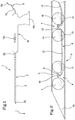
- Such a device therefore comprises at least one needle 2 extending along its own main direction "A" and provided with a longitudinal cavity 3.
- the needle 2 has a first operational and pointed end portion 2a, and a second end portion 2b, preferably connected to the handle of the device 1.
- the first end portion 2a may have a rectilinear orientation, aligned with the remaining part of the needle, or a curved orientation, with a variable angle according to the needs of the surgeon and lacerated area that needs suturing.
- the needle 2 is a substantially tubular body and the longitudinal cavity 3 is of the through type, which also extends along the main direction "A" between a first opening located at the first end portion 2a and a second opening located at the second end portion 2b.
- the cavity 3 is a duct laterally occluded by the needle wall and accessible from the openings.
- a first 4 and a second 5 member, as well as a surgical thread 6 are housed inside the needle 2, in particular inside the cavity.
- the members 4, 5 are shaped bodies to define an abutment to abut the outer wall of the meniscus during the pulling of the thread.
- these first 4 and second 5 members are slidably inserted into the longitudinal cavity 3 of the needle 2.
- first 4 and second 5 members are completely contained in the cavity 3 of the needle 2.
- Such members 4, 5 are arranged in succession along the main direction "A".
- Such members 4, 5 are also mutually connected through the surgical thread 6, which is also slidably inserted into the cavity 3 (as it will be better explained hereinafter).
- the first 4 and the second 5 members each comprise at least a pair of bodies 7, 8, 10, 11 connected together by means of a junction element 9,12.
- the bodies are each defined by a sphere 7, 8, 10, 11 or a substantially spherical body.
- the first member 4 comprises a first 7 and a second 8 sphere (or first and second body) that are connected one to the other by means of a special junction element 9.
- the second member 5 comprises a first 10 and a second 11 sphere (or first and second body) that are connected one to the other by means of a special junction element 12.
- such spheres 7, 8, 10, 11 have a diameter (or more generically a transverse size) substantially corresponding to an inside diameter of the cavity 3.
- the spheres 7, 8, 10, 11 are substantially shaped for the cavity 3.
- the spheres (or bodies) 7, 8, 10, 11 are made of polymeric material, more preferably of Poly-Ether-Ether-Ketone (PEEK) or Poly-L-lactide-co-D, L-lactide (PLDLLA).
- PEEK Poly-Ether-Ether-Ketone
- PLDLLA Poly-L-lactide-co-D, L-lactide
- the junction element 9, 12 is a bridge that connects the two spheres 7, 8, 10, 11 (or the two bodies) of each member 4, 5.
- such a junction element 9, 12 is flexible to allow a relative movement between said spheres (or bodies) 7, 8, 10, 11 of each member 4, 5.
- junction element 9, 12 can be made of a portion of surgical thread, preferably a multi-filament suturing thread.
- the junction element comprises a rigid pin extending between two ends each secured to a respective sphere.
- the junction element acts as a spacer between the two spheres of the individual member.
- the surgical thread 6 is slidably associated to said second member 5, more preferably (but not necessarily) to the junction element 12 of the member.
- the surgical thread 6 is associated to said second member 5 in correspondence of the respective junction element 12 by means of a knot or wrapping in which the thread 6 is maintained sliding.
- the thread 6 is slidably constrained to the junction element 12 so as to slide along the thread by varying the length of the thread portion 6a interposed between the first 4 and the second 5 member, thus allowing the laceration to be sutured.
- the thread defines the knot or wrapping that remains substantially in position on the second member 5 (or on the junction element 12), but it is slidable in such a way that the thread portion 6 defining the knot or the wrapping, changes upon pulling by the surgeon. Therefore, the knot or wrapping does not move, whereas the thread 6 that defines it, is slidable.
- this sliding knot or wrapping is a double thread point or the likes.
- the knot does not move along the tissues, but the thread 6 only moves linearly, which greatly reduces friction and the wear action of the thread.
- the surgical thread 6 extends between a first end portion 6a constrained to the first member 4, and a second end portion 6b, in use externally projecting to an end opposite the needle tip 2, or externally projecting to the second end portion 2b.
- the thread 6 comprises a first suturing portion 13, interposed between the first 4 and the second 5 member having a variable length, and a second pulling portion 14, which develops between the second member 5 and the second end portion 6b.
- the second end portion 6b can be held by the surgeon to pull the thread 6b, thus allowing the sliding thereof with respect to the second member 5 and reducing the length of the first portion 13 for suturing the laceration.
- the first portion the junction between the two members 4, 5 has a substantially linear development, i.e. without the presence of knots or wrapping between the two members 4, 5.
- the only functional knot or wrapping in the thread 6 is located at the second member 5, in particular at the junction element 12.
- the thread also has a fixing knot at its first end portion 6a to immovably constrain the same thread 6 to the junction portion 9 of the first member 4.
- the at least second sphere 8 of the first member 4 and spheres 10, 11, of the second member 5 have a peripheral groove 15 for housing the surgical thread 6 so as to minimize the size of the needle 2.
- the grooves 15 extend along the main direction "A" of the needle 2 and are accessible peripherally so as to house the thread 6 when the members are inside the needle 2, thus allowing its release after sliding out.
- all the spheres are equipped with such a groove 15.
- the surgical thread 6 presents a gauge between 2-0 and 0 on the USP scale, or preferably equal to 0 on the USP scale (about 0.350-0.399 mm).
- movement means 16 of the first 4 and second 5 member configured to translate each member 4, 5 from a rest position, in which it is housed inside the cavity 3 of the needle 2 to an operating position, in which it is proximal to or externally projecting from the tip of the needle 2. Therefore, the movement means 16 comprise at least one distal actuating member 16a from the tip (or from the first end portion 2a) of said needle 2 and operable by a user.
- the movement means 16 are projecting from the second end portion 2b of the needle 2 and comprise both a handle 16b and said actuating member 16a.
- the actuating member comprises at least a pusher element (not shown) slidably inserted into the needle 2 (or in the cavity) to get hold of the members 4, 5 and drive them from the rest position to the operating position.
- Such actuating member is also provided with a control portion, proximal to the handle, that can be used by a user (i.e. the surgeon) for manoeuvring the pusher element.
- the pusher element is movable in at least three configurations, namely a first configuration in which both members are in the rest position, a second configuration in which the first member is in the operating position and the second member is in the rest position (or in an intermediate position between the two) and a third configuration in which both members are in the operating position.
- the member 4' is used as a bone anchor, for example for attaching tissues such as tendons.
- the procedure or graft procedure is comparable to what has been described up to now, the only difference is related to the need to preliminarily drill the bone cortical tissue "CB” giving access to the organic component "SB" of the bone, i.e.the soft bone tissue.
- the method envisages to drill a hole in the bone by means of a tool able to realize an undercut "UC” between the cortical tissue "CB” and the bone organic component "SB".
- the cortical tissue "CB” has a through hole “H1" of diameter d1
- the bone organic component “SB” has a cavity “H2" substantially concentric to the hole “H1” and having a diameter d2 greater than diameter d1.
- a similar procedure may provide for the drilling of a through-hole in the bone such as to have just one through-hole "H1" of diameter d1; in such an alternative the member 4' is not placed inside the bone cavity, but outside it, so as to define, for example, an anchor for the new fixing of the bone in the event of fracture.
- the device is inserted in the hole "H1" so as to pass completely through the bone (anchor for the new fixing of the bone) or for access to the cavity “H2" (anchor for tissue fixation), without substantial modifications in the operating principle and in the structure of the device.
- the needle can be equivalently replaced by a tubular (or semi-tubular) body devoid of a tapered portion, whose only purpose is allowing the sliding of members on the inside.
- this embodiment of the device 1' may comprise a single member 4' (formed by two bodies 7', 8') insertable into the cavity "H2".
- the single member 4' is formed by at least two bodies 7' and 8' connected to one another by a junction element 9'.
- the suturing thread 6' is fixed to said junction element 9', preferably in a middle portion of said element.
- the two bodies 7', 8' each have a transverse size shorter than the hole diameter "H1" so that they can enter the cavity "H2", but which, after being added to the size of the other body, is longer than the diameter of the hole "H1", so as to be able to define the fixing anchor that is used by the surgeon, for example, to connect a tendon to the bone.
- the two bodies 7', 8' are spheres.
- the junction element 9' is preferably a flexible/elastic body that allows a simple rotation and does not hinder insertion.
- each body 7', 8' has a through hole within which an end of the junction element 9' is inserted.
- the junction element 9' has enlarged portions at its ends, so as to interfere with the edges of the corresponding through hole, thus preventing the body 7', 8' from sliding.
- the junction element develops substantially into the "V" shape, i.e. it has two angled portions extending between two free ends and a common vertex.
- the two free “V" ends are each connected to a respective body 7', 8'.
- the vertex is connected to the suturing thread 6'.
- the suturing thread 6 'and the junction element 9' are made in one piece. This allows to guarantee the correct positioning of the thread 6' with respect to the junction element 9' and therefore to facilitate rotation inside the cavity "H2".
- the thread 6' may be knotted or secured (also slidably) to the junction element 9' in some other way.
- the device 1' according to the present invention used as a bone anchor could be simplified (no needle and member reduction), without thereby deviating from what is the spirit of the present invention, of which, therefore, such application is fully part.
- the invention achieves the intended objects and provides important advantages.
Landscapes
- Health & Medical Sciences (AREA)
- Surgery (AREA)
- Life Sciences & Earth Sciences (AREA)
- Medical Informatics (AREA)
- Nuclear Medicine, Radiotherapy & Molecular Imaging (AREA)
- Engineering & Computer Science (AREA)
- Biomedical Technology (AREA)
- Heart & Thoracic Surgery (AREA)
- Molecular Biology (AREA)
- Animal Behavior & Ethology (AREA)
- General Health & Medical Sciences (AREA)
- Public Health (AREA)
- Veterinary Medicine (AREA)
- Rheumatology (AREA)
- Surgical Instruments (AREA)
- Materials For Medical Uses (AREA)
Claims (5)
- Nahtvorrichtung, umfassend:- einen rohrförmigen Körper (2), der mit einem Längshohlraum (3) ausgestattet ist, der entlang einer Hauptrichtung (A) zwischen einem ersten operativen Endabschnitt (2a) und einem zweiten Endabschnitt (2b) verläuft;- mindestens ein Element (4'), das verschiebbar in den genannten Längshohlraum (3) eingesetzt ist;- einen chirurgischen Faden (6'), der verschiebbar in den genannten Längshohlraum (3) eingesetzt und mit dem genannten Element (4') verbunden ist;wobei das genannte Element (4') nur ein Paar von miteinander mittels eines aus einem einzelnen Materialabschnitt bestehenden einzelnen Verbindungselements (9') zusammengefügten Körpern (7', 8') umfasst, wobei jeder Körper (7', 8') eine Durchgangsöffnung aufweist, in der ein Ende des Verbindungselements (9') eingesetzt ist,wobei der genannte chirurgische Faden (6') zwischen einem an dem Element (4) gehaltenen ersten Endabschnitt und einem zweiten Endabschnitt verläuft und bei Gebrauch außen zu dem zweiten Endabschnitt (2b) vorsteht und mittels eines Knotens oder einer Umhüllung, in der der Faden gleitend gehalten wird, verschiebbar an einem mittleren Abschnitt des genannten Verbindungselements (9') gehalten wird undwobei das genannte Paar von Körpern (7', 8') durch eine erste Kugel (7') und eine zweite Kugel (8') mit einer umlaufenden Nut (15) definiert wird, in der der chirurgische Faden (6) untergebracht ist, um die Größe des rohrförmigen Körpers (2) zu minimieren.
- Nahtvorrichtung nach Anspruch 1, wobei das genannte Verbindungselement (9') ein flexibler/elastischer Körper ist.
- Nahtvorrichtung nach Anspruch 1, wobei das Verbindungselement (9') an seinen Enden verbreiterte Abschnitte aufweist, um mit den Rändern der entsprechenden Durchgangsöffnung zu interferieren und so das Verschieben des Körpers (7', 8') zu unterbinden.
- Nahtvorrichtung nach irgendeinem der vorangegangenen Ansprüche, umfassend Bewegungsmittel (16) für das genannte Element (4'), die darauf ausgelegt sind, das genannte Element (4') aus einer Ruheposition, in der es im Inneren des Hohlraums (3) des rohrförmigen Körpers untergebracht ist, in eine Arbeitsposition, in der es proximal zu einem Ende des rohrförmigen Körpers ist oder nach außen von diesem vorsteht, zu versetzen.
- Nahtvorrichtung nach Anspruch 4, wobei die genannten Bewegungsmittel (16) mindestens ein Betätigungselement (16a) distal von dem genannten Ende des genannten rohrförmigen Körpers umfassen, das von einem Benutzer betätigt werden kann.
Applications Claiming Priority (3)
| Application Number | Priority Date | Filing Date | Title |
|---|---|---|---|
| ITUB2015A005738A ITUB20155738A1 (it) | 2015-11-19 | 2015-11-19 | Dispositivo di sutura, in particolare per la sutura di lacerazioni del menisco |
| PCT/IB2016/056886 WO2017085629A1 (en) | 2015-11-19 | 2016-11-16 | Suturing device, in particular for suturing lacerations of the meniscus |
| EP16822527.4A EP3376967B1 (de) | 2015-11-19 | 2016-11-16 | Nähvorrichtung, insbesondere zum nähen von schnittwunden des meniskus |
Related Parent Applications (2)
| Application Number | Title | Priority Date | Filing Date |
|---|---|---|---|
| EP16822527.4A Division EP3376967B1 (de) | 2015-11-19 | 2016-11-16 | Nähvorrichtung, insbesondere zum nähen von schnittwunden des meniskus |
| EP16822527.4A Division-Into EP3376967B1 (de) | 2015-11-19 | 2016-11-16 | Nähvorrichtung, insbesondere zum nähen von schnittwunden des meniskus |
Publications (2)
| Publication Number | Publication Date |
|---|---|
| EP3572007A1 EP3572007A1 (de) | 2019-11-27 |
| EP3572007B1 true EP3572007B1 (de) | 2022-01-05 |
Family
ID=55485128
Family Applications (2)
| Application Number | Title | Priority Date | Filing Date |
|---|---|---|---|
| EP16822527.4A Active EP3376967B1 (de) | 2015-11-19 | 2016-11-16 | Nähvorrichtung, insbesondere zum nähen von schnittwunden des meniskus |
| EP19182145.3A Active EP3572007B1 (de) | 2015-11-19 | 2016-11-16 | Nahtvorrichtung |
Family Applications Before (1)
| Application Number | Title | Priority Date | Filing Date |
|---|---|---|---|
| EP16822527.4A Active EP3376967B1 (de) | 2015-11-19 | 2016-11-16 | Nähvorrichtung, insbesondere zum nähen von schnittwunden des meniskus |
Country Status (7)
| Country | Link |
|---|---|
| US (2) | US11191535B2 (de) |
| EP (2) | EP3376967B1 (de) |
| JP (1) | JP6712319B2 (de) |
| AU (2) | AU2016357624B2 (de) |
| ES (2) | ES2757300T3 (de) |
| IT (1) | ITUB20155738A1 (de) |
| WO (1) | WO2017085629A1 (de) |
Families Citing this family (3)
| Publication number | Priority date | Publication date | Assignee | Title |
|---|---|---|---|---|
| US10869732B2 (en) * | 2016-06-15 | 2020-12-22 | Children's Hospital Medical Center | Spheric endo-luminal traction device for esophageal elongation |
| EP4398810A4 (de) * | 2021-09-09 | 2025-06-04 | Responsive Arthroscopy, LLC | Allnahtanker |
| US20260013851A1 (en) * | 2022-07-19 | 2026-01-15 | Anchora Medical Ltd. | Minimally-invasive endoscopic suturing device |
Family Cites Families (17)
| Publication number | Priority date | Publication date | Assignee | Title |
|---|---|---|---|---|
| JPS556871Y2 (de) * | 1976-11-25 | 1980-02-15 | ||
| US5437680A (en) * | 1987-05-14 | 1995-08-01 | Yoon; Inbae | Suturing method, apparatus and system for use in endoscopic procedures |
| US5810848A (en) * | 1996-08-21 | 1998-09-22 | Hayhurst; John O. | Suturing system |
| US20040122456A1 (en) * | 2002-12-11 | 2004-06-24 | Saadat Vahid C. | Methods and apparatus for gastric reduction |
| US7887551B2 (en) * | 1999-12-02 | 2011-02-15 | Smith & Nephew, Inc. | Soft tissue attachment and repair |
| DE20007777U1 (de) | 2000-04-29 | 2000-07-06 | Aesculap AG & Co. KG, 78532 Tuttlingen | Faden-Anker-System zum Verbinden von Gewebeteilen und Instrument zum Einsetzen eines Ankerimplantats |
| AU2007200095B2 (en) | 2000-11-02 | 2008-07-17 | Smith & Nephew, Inc. | Closure device and method for tissue repair |
| US7390332B2 (en) * | 2004-02-24 | 2008-06-24 | Depuy Mitek, Inc. | Methods and devices for repairing tissue |
| US7658750B2 (en) * | 2004-03-18 | 2010-02-09 | Warsaw Orthopedic, Inc. | Suture anchoring system and method |
| US8257394B2 (en) * | 2004-05-07 | 2012-09-04 | Usgi Medical, Inc. | Apparatus and methods for positioning and securing anchors |
| US9364212B2 (en) * | 2005-05-20 | 2016-06-14 | Neotract, Inc. | Suture anchoring devices and methods for use |
| US20060293709A1 (en) | 2005-06-24 | 2006-12-28 | Bojarski Raymond A | Tissue repair device |
| US20110029013A1 (en) * | 2008-02-15 | 2011-02-03 | Mcguckin James F | Vascular Hole Closure Device |
| AU2015202757B2 (en) | 2009-07-24 | 2017-03-30 | Depuy Mitek, Inc. | Methods and devices for repairing meniscal tissue |
| US8814904B2 (en) * | 2010-10-26 | 2014-08-26 | Ziptek LLC. | Surgical suture system |
| WO2014117107A1 (en) | 2013-01-28 | 2014-07-31 | Cartiva, Inc. | Systems and methods for orthopedic repair |
| US10285684B2 (en) * | 2013-09-26 | 2019-05-14 | Medos International Sàrl | Self-assembling suture anchor assembly, surgical kit, and surgical repair method |
-
2015
- 2015-11-19 IT ITUB2015A005738A patent/ITUB20155738A1/it unknown
-
2016
- 2016-11-16 EP EP16822527.4A patent/EP3376967B1/de active Active
- 2016-11-16 ES ES16822527T patent/ES2757300T3/es active Active
- 2016-11-16 ES ES19182145T patent/ES2904988T3/es active Active
- 2016-11-16 JP JP2018525720A patent/JP6712319B2/ja active Active
- 2016-11-16 US US15/777,485 patent/US11191535B2/en active Active
- 2016-11-16 EP EP19182145.3A patent/EP3572007B1/de active Active
- 2016-11-16 AU AU2016357624A patent/AU2016357624B2/en active Active
- 2016-11-16 WO PCT/IB2016/056886 patent/WO2017085629A1/en not_active Ceased
-
2019
- 2019-06-14 AU AU2019204195A patent/AU2019204195B2/en active Active
-
2021
- 2021-11-02 US US17/517,629 patent/US11812942B2/en active Active
Non-Patent Citations (1)
| Title |
|---|
| None * |
Also Published As
| Publication number | Publication date |
|---|---|
| AU2019204195B2 (en) | 2020-12-17 |
| JP2019502428A (ja) | 2019-01-31 |
| JP6712319B2 (ja) | 2020-06-17 |
| WO2017085629A1 (en) | 2017-05-26 |
| ES2904988T3 (es) | 2022-04-06 |
| EP3572007A1 (de) | 2019-11-27 |
| EP3376967A1 (de) | 2018-09-26 |
| AU2016357624A1 (en) | 2018-04-26 |
| ITUB20155738A1 (it) | 2017-05-19 |
| US11812942B2 (en) | 2023-11-14 |
| US20220125423A1 (en) | 2022-04-28 |
| US11191535B2 (en) | 2021-12-07 |
| AU2016357624B2 (en) | 2019-03-21 |
| ES2757300T3 (es) | 2020-04-28 |
| US20180368835A1 (en) | 2018-12-27 |
| EP3376967B1 (de) | 2019-08-21 |
| AU2019204195A1 (en) | 2019-07-11 |
Similar Documents
| Publication | Publication Date | Title |
|---|---|---|
| US11812942B2 (en) | Suturing device, in particular for suturing lacerations of the meniscus | |
| JP7295176B2 (ja) | 軟組織を固定するためのシステム及び方法 | |
| EP3316794B1 (de) | Nahtankersystem mit gewindestopfen | |
| EP2014241A2 (de) | Applikator für eine Naht-/Knopf-Konstruktion | |
| EP3113691B1 (de) | Einführsysteme für einen anker aus nahtmaterial | |
| EP3708098B1 (de) | Systeme und vorrichtungen zur fusion, stabilisierung oder fixierung von knochen | |
| US10743860B2 (en) | Methods and devices for passing sutures around anatomical structures | |
| JP2016083366A (ja) | 二頭筋腱固定術送達ツール | |
| US9642605B2 (en) | Vascular closure device suture tension limiting and indication mechanism | |
| EP3169248B1 (de) | Vorrichtung für chirurgische nähte | |
| EP3934546B1 (de) | Nahtspannungs- und -sicherungsvorrichtung und system | |
| EP2574307B1 (de) | Implantatseinführer | |
| JP2025501266A (ja) | ノットレスアンカー挿入器ツールの抜去 | |
| WO2013114347A1 (en) | Suture anchor with cleat formation to secure suture thread | |
| EP2986231B1 (de) | Freisetzungssystem | |
| CN107432757B (zh) | 用于可伸展锚定件的过度驱动预防 |
Legal Events
| Date | Code | Title | Description |
|---|---|---|---|
| PUAI | Public reference made under article 153(3) epc to a published international application that has entered the european phase |
Free format text: ORIGINAL CODE: 0009012 |
|
| STAA | Information on the status of an ep patent application or granted ep patent |
Free format text: STATUS: THE APPLICATION HAS BEEN PUBLISHED |
|
| AC | Divisional application: reference to earlier application |
Ref document number: 3376967 Country of ref document: EP Kind code of ref document: P |
|
| AK | Designated contracting states |
Kind code of ref document: A1 Designated state(s): AL AT BE BG CH CY CZ DE DK EE ES FI FR GB GR HR HU IE IS IT LI LT LU LV MC MK MT NL NO PL PT RO RS SE SI SK SM TR |
|
| STAA | Information on the status of an ep patent application or granted ep patent |
Free format text: STATUS: REQUEST FOR EXAMINATION WAS MADE |
|
| STAA | Information on the status of an ep patent application or granted ep patent |
Free format text: STATUS: EXAMINATION IS IN PROGRESS |
|
| 17P | Request for examination filed |
Effective date: 20200527 |
|
| RBV | Designated contracting states (corrected) |
Designated state(s): AL AT BE BG CH CY CZ DE DK EE ES FI FR GB GR HR HU IE IS IT LI LT LU LV MC MK MT NL NO PL PT RO RS SE SI SK SM TR |
|
| 17Q | First examination report despatched |
Effective date: 20200625 |
|
| GRAP | Despatch of communication of intention to grant a patent |
Free format text: ORIGINAL CODE: EPIDOSNIGR1 |
|
| STAA | Information on the status of an ep patent application or granted ep patent |
Free format text: STATUS: GRANT OF PATENT IS INTENDED |
|
| INTG | Intention to grant announced |
Effective date: 20210713 |
|
| GRAS | Grant fee paid |
Free format text: ORIGINAL CODE: EPIDOSNIGR3 |
|
| GRAA | (expected) grant |
Free format text: ORIGINAL CODE: 0009210 |
|
| STAA | Information on the status of an ep patent application or granted ep patent |
Free format text: STATUS: THE PATENT HAS BEEN GRANTED |
|
| AC | Divisional application: reference to earlier application |
Ref document number: 3376967 Country of ref document: EP Kind code of ref document: P |
|
| AK | Designated contracting states |
Kind code of ref document: B1 Designated state(s): AL AT BE BG CH CY CZ DE DK EE ES FI FR GB GR HR HU IE IS IT LI LT LU LV MC MK MT NL NO PL PT RO RS SE SI SK SM TR |
|
| REG | Reference to a national code |
Ref country code: GB Ref legal event code: FG4D |
|
| REG | Reference to a national code |
Ref country code: CH Ref legal event code: EP |
|
| REG | Reference to a national code |
Ref country code: AT Ref legal event code: REF Ref document number: 1459825 Country of ref document: AT Kind code of ref document: T Effective date: 20220115 |
|
| REG | Reference to a national code |
Ref country code: DE Ref legal event code: R096 Ref document number: 602016068243 Country of ref document: DE |
|
| REG | Reference to a national code |
Ref country code: IE Ref legal event code: FG4D |
|
| REG | Reference to a national code |
Ref country code: ES Ref legal event code: FG2A Ref document number: 2904988 Country of ref document: ES Kind code of ref document: T3 Effective date: 20220406 |
|
| REG | Reference to a national code |
Ref country code: LT Ref legal event code: MG9D |
|
| REG | Reference to a national code |
Ref country code: NL Ref legal event code: MP Effective date: 20220105 |
|
| REG | Reference to a national code |
Ref country code: AT Ref legal event code: MK05 Ref document number: 1459825 Country of ref document: AT Kind code of ref document: T Effective date: 20220105 |
|
| PG25 | Lapsed in a contracting state [announced via postgrant information from national office to epo] |
Ref country code: NL Free format text: LAPSE BECAUSE OF FAILURE TO SUBMIT A TRANSLATION OF THE DESCRIPTION OR TO PAY THE FEE WITHIN THE PRESCRIBED TIME-LIMIT Effective date: 20220105 |
|
| PG25 | Lapsed in a contracting state [announced via postgrant information from national office to epo] |
Ref country code: SE Free format text: LAPSE BECAUSE OF FAILURE TO SUBMIT A TRANSLATION OF THE DESCRIPTION OR TO PAY THE FEE WITHIN THE PRESCRIBED TIME-LIMIT Effective date: 20220105 Ref country code: RS Free format text: LAPSE BECAUSE OF FAILURE TO SUBMIT A TRANSLATION OF THE DESCRIPTION OR TO PAY THE FEE WITHIN THE PRESCRIBED TIME-LIMIT Effective date: 20220105 Ref country code: PT Free format text: LAPSE BECAUSE OF FAILURE TO SUBMIT A TRANSLATION OF THE DESCRIPTION OR TO PAY THE FEE WITHIN THE PRESCRIBED TIME-LIMIT Effective date: 20220505 Ref country code: NO Free format text: LAPSE BECAUSE OF FAILURE TO SUBMIT A TRANSLATION OF THE DESCRIPTION OR TO PAY THE FEE WITHIN THE PRESCRIBED TIME-LIMIT Effective date: 20220405 Ref country code: LT Free format text: LAPSE BECAUSE OF FAILURE TO SUBMIT A TRANSLATION OF THE DESCRIPTION OR TO PAY THE FEE WITHIN THE PRESCRIBED TIME-LIMIT Effective date: 20220105 Ref country code: HR Free format text: LAPSE BECAUSE OF FAILURE TO SUBMIT A TRANSLATION OF THE DESCRIPTION OR TO PAY THE FEE WITHIN THE PRESCRIBED TIME-LIMIT Effective date: 20220105 Ref country code: BG Free format text: LAPSE BECAUSE OF FAILURE TO SUBMIT A TRANSLATION OF THE DESCRIPTION OR TO PAY THE FEE WITHIN THE PRESCRIBED TIME-LIMIT Effective date: 20220405 |
|
| PG25 | Lapsed in a contracting state [announced via postgrant information from national office to epo] |
Ref country code: PL Free format text: LAPSE BECAUSE OF FAILURE TO SUBMIT A TRANSLATION OF THE DESCRIPTION OR TO PAY THE FEE WITHIN THE PRESCRIBED TIME-LIMIT Effective date: 20220105 Ref country code: LV Free format text: LAPSE BECAUSE OF FAILURE TO SUBMIT A TRANSLATION OF THE DESCRIPTION OR TO PAY THE FEE WITHIN THE PRESCRIBED TIME-LIMIT Effective date: 20220105 Ref country code: GR Free format text: LAPSE BECAUSE OF FAILURE TO SUBMIT A TRANSLATION OF THE DESCRIPTION OR TO PAY THE FEE WITHIN THE PRESCRIBED TIME-LIMIT Effective date: 20220406 Ref country code: FI Free format text: LAPSE BECAUSE OF FAILURE TO SUBMIT A TRANSLATION OF THE DESCRIPTION OR TO PAY THE FEE WITHIN THE PRESCRIBED TIME-LIMIT Effective date: 20220105 Ref country code: AT Free format text: LAPSE BECAUSE OF FAILURE TO SUBMIT A TRANSLATION OF THE DESCRIPTION OR TO PAY THE FEE WITHIN THE PRESCRIBED TIME-LIMIT Effective date: 20220105 |
|
| PG25 | Lapsed in a contracting state [announced via postgrant information from national office to epo] |
Ref country code: IS Free format text: LAPSE BECAUSE OF FAILURE TO SUBMIT A TRANSLATION OF THE DESCRIPTION OR TO PAY THE FEE WITHIN THE PRESCRIBED TIME-LIMIT Effective date: 20220505 |
|
| REG | Reference to a national code |
Ref country code: DE Ref legal event code: R097 Ref document number: 602016068243 Country of ref document: DE |
|
| PG25 | Lapsed in a contracting state [announced via postgrant information from national office to epo] |
Ref country code: SM Free format text: LAPSE BECAUSE OF FAILURE TO SUBMIT A TRANSLATION OF THE DESCRIPTION OR TO PAY THE FEE WITHIN THE PRESCRIBED TIME-LIMIT Effective date: 20220105 Ref country code: SK Free format text: LAPSE BECAUSE OF FAILURE TO SUBMIT A TRANSLATION OF THE DESCRIPTION OR TO PAY THE FEE WITHIN THE PRESCRIBED TIME-LIMIT Effective date: 20220105 Ref country code: RO Free format text: LAPSE BECAUSE OF FAILURE TO SUBMIT A TRANSLATION OF THE DESCRIPTION OR TO PAY THE FEE WITHIN THE PRESCRIBED TIME-LIMIT Effective date: 20220105 Ref country code: EE Free format text: LAPSE BECAUSE OF FAILURE TO SUBMIT A TRANSLATION OF THE DESCRIPTION OR TO PAY THE FEE WITHIN THE PRESCRIBED TIME-LIMIT Effective date: 20220105 Ref country code: DK Free format text: LAPSE BECAUSE OF FAILURE TO SUBMIT A TRANSLATION OF THE DESCRIPTION OR TO PAY THE FEE WITHIN THE PRESCRIBED TIME-LIMIT Effective date: 20220105 Ref country code: CZ Free format text: LAPSE BECAUSE OF FAILURE TO SUBMIT A TRANSLATION OF THE DESCRIPTION OR TO PAY THE FEE WITHIN THE PRESCRIBED TIME-LIMIT Effective date: 20220105 |
|
| PLBE | No opposition filed within time limit |
Free format text: ORIGINAL CODE: 0009261 |
|
| STAA | Information on the status of an ep patent application or granted ep patent |
Free format text: STATUS: NO OPPOSITION FILED WITHIN TIME LIMIT |
|
| PG25 | Lapsed in a contracting state [announced via postgrant information from national office to epo] |
Ref country code: AL Free format text: LAPSE BECAUSE OF FAILURE TO SUBMIT A TRANSLATION OF THE DESCRIPTION OR TO PAY THE FEE WITHIN THE PRESCRIBED TIME-LIMIT Effective date: 20220105 |
|
| 26N | No opposition filed |
Effective date: 20221006 |
|
| PG25 | Lapsed in a contracting state [announced via postgrant information from national office to epo] |
Ref country code: SI Free format text: LAPSE BECAUSE OF FAILURE TO SUBMIT A TRANSLATION OF THE DESCRIPTION OR TO PAY THE FEE WITHIN THE PRESCRIBED TIME-LIMIT Effective date: 20220105 |
|
| PG25 | Lapsed in a contracting state [announced via postgrant information from national office to epo] |
Ref country code: MC Free format text: LAPSE BECAUSE OF FAILURE TO SUBMIT A TRANSLATION OF THE DESCRIPTION OR TO PAY THE FEE WITHIN THE PRESCRIBED TIME-LIMIT Effective date: 20220105 |
|
| REG | Reference to a national code |
Ref country code: BE Ref legal event code: MM Effective date: 20221130 |
|
| P01 | Opt-out of the competence of the unified patent court (upc) registered |
Effective date: 20230628 |
|
| PG25 | Lapsed in a contracting state [announced via postgrant information from national office to epo] |
Ref country code: LU Free format text: LAPSE BECAUSE OF NON-PAYMENT OF DUE FEES Effective date: 20221116 |
|
| PG25 | Lapsed in a contracting state [announced via postgrant information from national office to epo] |
Ref country code: IE Free format text: LAPSE BECAUSE OF NON-PAYMENT OF DUE FEES Effective date: 20221116 |
|
| PG25 | Lapsed in a contracting state [announced via postgrant information from national office to epo] |
Ref country code: BE Free format text: LAPSE BECAUSE OF NON-PAYMENT OF DUE FEES Effective date: 20221130 |
|
| PG25 | Lapsed in a contracting state [announced via postgrant information from national office to epo] |
Ref country code: HU Free format text: LAPSE BECAUSE OF FAILURE TO SUBMIT A TRANSLATION OF THE DESCRIPTION OR TO PAY THE FEE WITHIN THE PRESCRIBED TIME-LIMIT; INVALID AB INITIO Effective date: 20161116 |
|
| PG25 | Lapsed in a contracting state [announced via postgrant information from national office to epo] |
Ref country code: CY Free format text: LAPSE BECAUSE OF FAILURE TO SUBMIT A TRANSLATION OF THE DESCRIPTION OR TO PAY THE FEE WITHIN THE PRESCRIBED TIME-LIMIT Effective date: 20220105 |
|
| PG25 | Lapsed in a contracting state [announced via postgrant information from national office to epo] |
Ref country code: MK Free format text: LAPSE BECAUSE OF FAILURE TO SUBMIT A TRANSLATION OF THE DESCRIPTION OR TO PAY THE FEE WITHIN THE PRESCRIBED TIME-LIMIT Effective date: 20220105 |
|
| PG25 | Lapsed in a contracting state [announced via postgrant information from national office to epo] |
Ref country code: TR Free format text: LAPSE BECAUSE OF FAILURE TO SUBMIT A TRANSLATION OF THE DESCRIPTION OR TO PAY THE FEE WITHIN THE PRESCRIBED TIME-LIMIT Effective date: 20220105 |
|
| PG25 | Lapsed in a contracting state [announced via postgrant information from national office to epo] |
Ref country code: MT Free format text: LAPSE BECAUSE OF FAILURE TO SUBMIT A TRANSLATION OF THE DESCRIPTION OR TO PAY THE FEE WITHIN THE PRESCRIBED TIME-LIMIT Effective date: 20220105 |
|
| REG | Reference to a national code |
Ref country code: CH Ref legal event code: U11 Free format text: ST27 STATUS EVENT CODE: U-0-0-U10-U11 (AS PROVIDED BY THE NATIONAL OFFICE) Effective date: 20251201 |
|
| PGFP | Annual fee paid to national office [announced via postgrant information from national office to epo] |
Ref country code: DE Payment date: 20251126 Year of fee payment: 10 |
|
| PGFP | Annual fee paid to national office [announced via postgrant information from national office to epo] |
Ref country code: GB Payment date: 20251125 Year of fee payment: 10 |
|
| PGFP | Annual fee paid to national office [announced via postgrant information from national office to epo] |
Ref country code: IT Payment date: 20251127 Year of fee payment: 10 |
|
| PGFP | Annual fee paid to national office [announced via postgrant information from national office to epo] |
Ref country code: FR Payment date: 20251124 Year of fee payment: 10 |
|
| PGFP | Annual fee paid to national office [announced via postgrant information from national office to epo] |
Ref country code: CH Payment date: 20251201 Year of fee payment: 10 |
|
| PGFP | Annual fee paid to national office [announced via postgrant information from national office to epo] |
Ref country code: ES Payment date: 20251209 Year of fee payment: 10 |